EP3495129A1 - Fahrzeugluftreifen, vulkanisationswerkzeug zur herstellung eines derartigen fahrzeugluftreifens und verfahren zur herstellung eines fahrzeugluftreifens unter verwendung eines vulkanisationswerkzeuges - Google Patents
Fahrzeugluftreifen, vulkanisationswerkzeug zur herstellung eines derartigen fahrzeugluftreifens und verfahren zur herstellung eines fahrzeugluftreifens unter verwendung eines vulkanisationswerkzeuges Download PDFInfo
- Publication number
- EP3495129A1 EP3495129A1 EP18194988.4A EP18194988A EP3495129A1 EP 3495129 A1 EP3495129 A1 EP 3495129A1 EP 18194988 A EP18194988 A EP 18194988A EP 3495129 A1 EP3495129 A1 EP 3495129A1
- Authority
- EP
- European Patent Office
- Prior art keywords
- pneumatic vehicle
- side wall
- vehicle tire
- tire
- pneumatic
- Prior art date
- Legal status (The legal status is an assumption and is not a legal conclusion. Google has not performed a legal analysis and makes no representation as to the accuracy of the status listed.)
- Granted
Links
Images

Classifications
-
- B—PERFORMING OPERATIONS; TRANSPORTING
- B29—WORKING OF PLASTICS; WORKING OF SUBSTANCES IN A PLASTIC STATE IN GENERAL
- B29D—PRODUCING PARTICULAR ARTICLES FROM PLASTICS OR FROM SUBSTANCES IN A PLASTIC STATE
- B29D30/00—Producing pneumatic or solid tyres or parts thereof
- B29D30/06—Pneumatic tyres or parts thereof (e.g. produced by casting, moulding, compression moulding, injection moulding, centrifugal casting)
- B29D30/0601—Vulcanising tyres; Vulcanising presses for tyres
- B29D30/0606—Vulcanising moulds not integral with vulcanising presses
-
- B—PERFORMING OPERATIONS; TRANSPORTING
- B29—WORKING OF PLASTICS; WORKING OF SUBSTANCES IN A PLASTIC STATE IN GENERAL
- B29D—PRODUCING PARTICULAR ARTICLES FROM PLASTICS OR FROM SUBSTANCES IN A PLASTIC STATE
- B29D30/00—Producing pneumatic or solid tyres or parts thereof
- B29D30/06—Pneumatic tyres or parts thereof (e.g. produced by casting, moulding, compression moulding, injection moulding, centrifugal casting)
- B29D30/0601—Vulcanising tyres; Vulcanising presses for tyres
- B29D30/0606—Vulcanising moulds not integral with vulcanising presses
- B29D2030/0607—Constructional features of the moulds
- B29D2030/0612—Means for forming recesses or protrusions in the tyres, e.g. grooves or ribs, to create the tread or sidewalls patterns
-
- B—PERFORMING OPERATIONS; TRANSPORTING
- B29—WORKING OF PLASTICS; WORKING OF SUBSTANCES IN A PLASTIC STATE IN GENERAL
- B29D—PRODUCING PARTICULAR ARTICLES FROM PLASTICS OR FROM SUBSTANCES IN A PLASTIC STATE
- B29D30/00—Producing pneumatic or solid tyres or parts thereof
- B29D30/06—Pneumatic tyres or parts thereof (e.g. produced by casting, moulding, compression moulding, injection moulding, centrifugal casting)
- B29D30/0601—Vulcanising tyres; Vulcanising presses for tyres
- B29D30/0606—Vulcanising moulds not integral with vulcanising presses
- B29D2030/0607—Constructional features of the moulds
- B29D2030/0618—Annular elements, e.g. rings, for moulding the tyre shoulder areas
-
- B—PERFORMING OPERATIONS; TRANSPORTING
- B29—WORKING OF PLASTICS; WORKING OF SUBSTANCES IN A PLASTIC STATE IN GENERAL
- B29D—PRODUCING PARTICULAR ARTICLES FROM PLASTICS OR FROM SUBSTANCES IN A PLASTIC STATE
- B29D30/00—Producing pneumatic or solid tyres or parts thereof
- B29D30/06—Pneumatic tyres or parts thereof (e.g. produced by casting, moulding, compression moulding, injection moulding, centrifugal casting)
- B29D30/0601—Vulcanising tyres; Vulcanising presses for tyres
- B29D30/0606—Vulcanising moulds not integral with vulcanising presses
- B29D30/0629—Vulcanising moulds not integral with vulcanising presses with radially movable sectors
Definitions
- the invention relates to a pneumatic vehicle tire, a vulcanization tool for producing such a pneumatic vehicle tire and a method for producing a pneumatic vehicle tire using a vulcanization tool.
- a pneumatic vehicle tire having a profiled tread, which merges into a respective side wall on both sides and whose ends are formed by a respective tire bead.
- a pneumatic vehicle tire is produced in a likewise described vulcanization tool, which consists of a plurality of radially movable arranged profile segments of a segment ring, which serve to generate the profiling of the tread of the pneumatic vehicle tire.
- the vulcanization tool has a plurality of side wall shells for forming the side walls, wherein a mold parting plane is defined between the segment ring and the side wall shells.
- the mold parting plane is not necessarily to be understood as a continuous level. Rather, it can also be discontinued or stepped within the vulcanization tool.
- the mold parting plane in a broader sense represents at least one contact surface between the side wall shells and the segment ring consisting of several profile segments.
- the DE 2014 212 346 A1 discloses a solution for reducing the generation of the spews, which consists in that a groove extends along the mold parting plane which is formed partly in the profile segments and partly in the respective side wall shell, the mold parting plane being at the bottom of the groove.
- the projections on the tire have a height of 1.5 mm to 2.5 mm and at its base on the side wall has a width of also 1.5 mm to 2.5 mm. In other words, the projections have a uniform geometry.
- the DE 696 00 888 T2 relates to a pneumatic vehicle tire in which a plurality of recesses and a circumferential groove are provided in the region of the mold parting plane, each recess having a depth of 0.5 mm to 5.0 mm and a maximum circumferential line of 5.0 mm to 10.0 mm ,
- a solution has the disadvantage that the shoulder region of the pneumatic vehicle tire, which is located in the transition between the tread and the side wall, is relatively heavily structured, which in turn causes the aerodynamics of the pneumatic vehicle tire deteriorates. In addition to a deterioration in fuel consumption of the motor vehicle equipped with the pneumatic vehicle tire, this can also result in increased noise development in the operating state of the pneumatic vehicle tire.
- the invention has for its object to provide a pneumatic vehicle tire, which is designed aerodynamically low and has shoots that can be separated with reliable quality and in a simple manner and with little effort from the pneumatic vehicle tire, without causing damage to the side wall.
- a vulcanization tool is to be specified with which such a pneumatic vehicle tire can be produced.
- the object of the invention is to define a method with which the pneumatic vehicle tire can be produced in the vulcanization tool.
- a pneumatic vehicle tire with a profiled tread, which merges into a respective side wall on both sides, whose ends are formed by a respective tire bead and which is produced in a Vulkanisationstechnikmaschine consisting of a plurality of radially movable arranged profile segments of a segment ring, for profiling the tread and consists of a plurality of side wall shells for forming the side walls, wherein between the segment ring and the side wall shells a mold parting plane is defined according to the invention further developed such that the vehicle pneumatic tire at its defined by the direction of the pneumatic vehicle tire outside at least partially, extending in the circumferential direction, from the side of the Running surface, oriented in the direction of the tire bead, ramp-like Has rising elevation and subsequent to the survey plateau surface.
- the invention goes a completely new way.
- a bead-shaped projection on the outside of the side wall of the vehicle pneumatic tire is not simply provided, but a specially designed contour with a ramp-like elevation at which the trimming blade can be optimally applied and guided along, which means that the resulting sprouted be removed almost residue-free can, without causing damage to the pneumatic vehicle tire are recorded.
- the pneumatic vehicle tire has an optimized, uniform outer surface of the side wall and thus improved aerodynamics in comparison with conventional pneumatic vehicle tires. This leads to a reduction in the noise generated during driving and to a reduction in fuel consumption of the motor vehicle equipped with the pneumatic vehicle tire.
- the mold parting plane is arranged in the region of the elevation in front of the plateau surface.
- the transition of the plateau surface to the surface of the side wall of the pneumatic vehicle tire can be designed differently and executed according to a first, further developing measure of the invention such that the plateau surface a transition to Side wall of the pneumatic vehicle tire and the height of the transition in relation to the outside of the side wall of the pneumatic vehicle tire is less than the height of the survey.
- there is here a gradation so that the plateau surface, viewed in cross-section, has a tendency to the outer surface of the side wall of the pneumatic vehicle tire.
- there is sufficient rubber material available in this area to optimally guide the trim blade and to be able to separate the entire shoot evenly.
- the plateau surface may also be formed as a ring on the outside of the side wall, so that their course in this case over the entire width of the plateau surfaces is equidistant to the outside of the side surface of the pneumatic vehicle tire.
- plateau surface is designed to be expiring to the surface of the side wall of the vehicle pneumatic tire and thus merges seamlessly into the side wall. In this case, therefore, no transition between the plateau surface and the outside of the side wall of the pneumatic vehicle tire is given. In this way, an overall very uniform transition of the shoot to the outer surface of the side wall is created.
- the entire expulsion has a localized area on the side wall of the pneumatic vehicle tire. This is necessary in order to be able to separate it optimally by means of a trimming knife. Therefore, it is advantageous if the width of the plateau surface to be considered in the direction of the course of the plateau surface, starting from the running surface, in the direction of the tire bead is between 1 mm and 4 mm. However, a preferred width of the plateau surfaces is 2 mm.
- the height of the elevation before the plateau surface is between 0.2 mm and 0.6 mm. In this case, a height of 0.3 mm is preferably provided.
- the vulcanization tool according to the invention for the production of a pneumatic vehicle tire has a plurality of radially movable arranged profile segments of a segment ring for profiling the tread and a plurality of side wall shells for forming the side walls, wherein between the segment ring and the side wall shells a mold parting plane is defined and only the side wall shells have a complementary to the survey and the plateau recess.
- the vulcanization tool has a segment ring constructed in a very simple manner, so that it therefore only has a negative contour relative to the pneumatic vehicle tire according to the invention in the area of the side wall shells and is consequently adapted to it.
- the vulcanization tool is designed such that the expulsion of the vehicle pneumatic tire to be produced in the vulcanization tool can penetrate into the predetermined geometry of the vulcanization tool and thereby produce the special, inventive surface structure on the side wall of the pneumatic vehicle tire, which is later separated with a trimming blade , Since these special geometries are incorporated directly into the vulcanization tool, no significant, additional manufacturing effort is required to form the elevation and the plateau surface on the pneumatic vehicle tire.
- the separation is carried out by a cutting process, which is preferably a trimming blade cutting.
- the separation can be done manually or automatically.
- An automated separation which can be done for example by means of a suitable robot, thereby saving additional work time and manpower, so that the manual activities in the manufacture of a pneumatic vehicle tire can be significantly reduced.
- FIG. 1 is a detail of a cross-section through a vehicle pneumatic tire 1 is shown, which is inserted into a vulcanization tool and in a conventional manner has a tread equipped tread 2, which merges into a respective side wall 3 on both sides.
- the side wall 3 terminates in a tire bead, which serves for airtight insertion of the pneumatic vehicle tire 1 in a rim of a vehicle wheel, wherein the tire bead and the rim in the FIG. 1 are not shown.
- the Vulkanisationswerkmaschine consists of a segment ring 4, which in turn is composed of a plurality of radially movable arranged profile segments, so that the Vulkanisationswerkmaschine can be opened and closed to insert the green tire, which is also referred to as "green tire” in the vulcanization tool and to be able to remove the pneumatic vehicle tire 1 after its completion from the vulcanization tool.
- the removable segment ring 4 is releasably connected to form a seal with a plurality of side wall shells 5, wherein the connecting portion forms a mold parting plane 6.
- the side wall shells 5 are adapted to form the side walls 3 of the pneumatic vehicle tire 1 when it is vulcanized in the vulcanization tool.
- the inner surface of the side wall shells 5 has a complementary to the outer sides 7 of the side walls 3 geometry.
- the vehicle pneumatic tire 1 is equipped according to the invention with a geometry which can be easily separated after its completion by means of a trimming blade.
- a geometry which can be easily separated after its completion by means of a trimming blade.
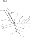
- the outside 7 of the side wall 3 of the pneumatic vehicle tire 1 starting from the tread 2 in the direction of in the FIG. 2 Tire bead, not shown, ie opposite to the direction of the arrow "2", so there is to be designated as shoot, raised geometry from a ramp-like elevation 8, which merges into a plateau 9, the width of which is 2 mm in the illustrated example. It should be noted that both the survey 8, as well as the plateau 9 in the FIG.
- the plateau surface 9 and thus also the first elevation 8 in the illustrated example with respect to the outer side 7 of the side surface 3 of the pneumatic vehicle tire 1 has a height of 0.3 mm.
- Another special feature is the in FIG. 2 shown embodiment in that the plateau surface 9 has an inclination to the outside 7 of the side wall 3, which means that the plateau surface 9 has a transition 10 to the side wall 3, the height in relation to the outside 7 of the side wall 3 of the pneumatic vehicle tire 1 is lower than that Height of the survey 8.
- the mold parting plane 6 extends at the end of the ramp-like elevation 8 and in front of the plateau surface 9.
- the detail enlarged enlarged sectional view in FIG. 2 runs through a profile recess of the pneumatic vehicle tire 1, so that in the upper, tread-side portion of the illustrated part of the pneumatic vehicle tire 1, a profile recess 11 can be seen.
Landscapes
- Engineering & Computer Science (AREA)
- Mechanical Engineering (AREA)
- Moulds For Moulding Plastics Or The Like (AREA)
- Heating, Cooling, Or Curing Plastics Or The Like In General (AREA)
Abstract
Description
- Die Erfindung betrifft einen Fahrzeugluftreifen, ein Vulkanisationswerkzeug zur Herstellung eines derartigen Fahrzeugluftreifens und ein Verfahren zur Herstellung eines Fahrzeugluftreifens unter Verwendung eines Vulkanisationswerkzeuges.
- Aus der
DE 2014 212 346 A1 ist bereits ein Fahrzeugluftreifen bekannt, der eine profilierte Lauffläche aufweist, die beidseitig in je eine Seitenwand übergeht und deren Enden durch je einen Reifenwulst gebildet werden. Ein derartiger Fahrzeugluftreifen wird in einem ebenfalls beschriebenen Vulkanisationswerkzeug hergestellt, das aus mehreren, in radialer Richtung bewegbar angeordneten Profilsegmenten eines Segmentringes besteht, die der Erzeugung der Profilierung der Lauffläche des Fahrzeugluftreifens dienen. Darüber hinaus weist das Vulkanisationswerkzeug mehrere Seitenwandschalen zur Ausbildung der Seitenwände auf, wobei zwischen dem Segmentring und den Seitenwandschalen eine Formtrennebene definiert ist. Dies hat zur Folge, dass die einzelnen Elemente des Vulkanisationswerkzeuges voneinander getrennt werden können, um einen Reifenrohling, der auch als "grüner Reifen" bezeichnet wird, in das Vulkanisationswerkzeug einsetzen und den fertig gestellten, also vulkanisierten Fahrzeugluftreifen aus dem Vulkanisationswerkzeug entnehmen zu können. Die Formtrennebene ist dabei nicht zwangsläufig als eine durchgehende Ebene zu verstehen. Vielmehr kann sie innerhalb des Vulkanisationswerkzeuges auch abgesetzt oder gestuft sein. Letztlich stellt die Formtrennebene im weiteren Sinne mindestens eine Berührungsfläche zwischen den Seitenwandschalen und dem aus mehreren Profilsegmenten bestehenden Segmentring dar. Während des Schließens des Vulkanisationswerkzeuges ist es durch den Schließdruck nahezu unvermeidbar, dass Teile des Gummiwerkstoffes des Reifenrohlings zwischen die Seitenwandschalen und den Segmentring gepresst werden, was dazu führt, dass im Bereich der Formtrennebene Austriebe entstehen können. Zudem dringt beim Vulkanisieren überschüssiges Gummimaterial des in das Vulkanisationswerkzeug eingesetzten Reifenrohlings in die Formtrennebene ein, sodass am fertig vulkanisierten Fahrzeugluftreifen auch dadurch Austriebe entstehen, die zumeist einen kreisförmig, zwischen der Seitenwand und der Lauffläche umlaufenden, dünnen und abstehenden Gummifilm bilden. Diese Austriebe sind am Fahrzeugluftreifen jedoch nicht erwünscht und werden durch das so genannte "Trimmen", manuell mit hierfür geeigneten Trimmmessern entfernt. Damit das Trimmen der Austriebe leichter fällt, ist es bekannt, die Profilsegmente des Segmentringes und/oder die Seitenwandschalen derart auszubilden, dass auf einer oder auf beiden Seiten der Formtrennebene Gummikeile als umlaufende Rippen am Fahrzeugluftreifen ausgebildet werden, die aufgrund ihrer Erhöhung das Trimmen erleichtern sollen. Diese umlaufenden Rippen am Fahrzeugluftreifen erfordern jedoch zusätzliches Gummimaterial, sodass sich dadurch die Herstellungskosten und das Reifengewicht erhöhen, wobei Letzteres zu einer Verschlechterung der Aerodynamik des Fahrzeugluftreifens im Betriebszustand führt.
DieDE 2014 212 346 A1 offenbart zur Reduzierung der Entstehung der Austriebe eine Lösung, die darin besteht, dass entlang der Formtrennebene eine Nut verläuft, welche zum Teil in den Profilsegmenten und zum Teil in der jeweiligen Seitenwandschale ausgebildet ist, wobei sich die Formtrennebene am Boden der Nut befindet. Der dadurch am Fahrzeugluftreifen entstehende Vorsprung ermöglicht einen sauberen Schnitt beim Abtrennen der Austriebe. Dabei wird ausgeführt, dass der Vorsprung komplett, teilweise oder größtenteils abgeschnitten werden kann, sodass dieser Bereich sehr gut trimmbar ist und auch im Vorsprung gegebenenfalls ausgebildete Stufen, die durch ein etwaiges Verschieben der Formteile des Vulkanisationswerkzeuges relativ zueinander gebildet worden sind, entfernt werden können. Auf besonders einfache und rationelle Weise wird damit ein teilweises oder komplettes Abschneiden der Vorsprünge möglich, die gemäß des Offenbarungsgehaltes der Druckschrift im Querschnitt dreieckförmig oder gerundet oder zum Beispiel kuppelförmig gerundet, ausgeführt sind. Auch die Dimensionierung der Vorsprünge spielt laut derDE 2014 212 346 A1 eine gewisse Rolle, da sich sowohl zu große als auch zu kleine Vorsprünge schwieriger abschneiden lassen. Es wird daher in der Druckschrift als vorteilhaft beschrieben, wenn die Vorsprünge am Reifen eine Höhe von 1,5 mm bis 2,5 mm und an ihrer Basis an der Seitenwand eine Breite von ebenfalls 1,5 mm bis 2,5 mm aufweisen. Anders ausgedrückt weisen die Vorsprünge eine gleichmäßige Geometrie auf. - Aus der
DE 10 2009 044 362 A1 ist es darüber hinaus bekannt, in den Seitenwandschalen und/oder den Profilsegmenten des Segmentringes des Vulkanisationswerkzeuges an oder nahe des Bereiches der Formtrennebene und entlang dieser, einzelne, in axialer Richtung verlaufende Kanäle vorzusehen. Es werden daher in dem Vulkanisationswerkzeug für überschüssiges Gummimaterial gezielt Aufnahmeräume für überschüssiges Gummimaterial zur Verfügung gestellt. In dem ebenfalls beschriebenen, fertig gestellten Fahrzeugluftreifen entstehen dadurch einzelne, kleine, stiftartige Gummigrate, die sich leichter entfernen lassen sollen als die sonst üblichen Austriebe. Es hat sich jedoch herausgestellt, dass sich auch diese einzelnen, stiftartigen Austriebe relativ schwer trimmen lassen, da sie recht flexibel sind und sich dadurch vom Trimmmesser nicht gut erfassen lassen. - Die
DE 696 00 888 T2 betrifft einen Fahrzeugluftreifen, bei dem im Bereich der Formtrennebene eine Mehrzahl von Vertiefungen und eine Umfangsnut vorgesehen sind, wobei jede Vertiefung eine Tiefe von 0,5 mm bis 5,0 mm und eine maximale Umfangslinie von 5,0 mm bis 10,0 mm aufweist. Eine derartige Lösung hat den Nachteil, dass der Schulterbereich des Fahrzeugluftreifens, der sich im Übergang zwischen der Lauffläche und der Seitenwand befindet, relativ stark strukturiert ist, was wiederum dazu führt, dass sich die Aerodynamik des Fahrzeugluftreifens verschlechtert. Dies kann neben einer Verschlechterung des Kraftstoffverbrauchs des mit dem Fahrzeugluftreifen ausgestatteten Kraftfahrzeuges auch zur Folge haben, dass eine verstärkte Geräuschentwicklung im Betriebszustand des Fahrzeugluftreifens zu verzeichnen ist. - Aus dem bekannten Stand der Technik ergibt sich, dass bisher noch keine befriedigende Lösung gefunden wurde, einen Fahrzeugluftreifen mittels eines Vulkanisationswerkzeuges herzustellen, der aerodynamisch günstig gestaltet ist, keine Anfälligkeit für Rissbildungen aufweist und bei dem die nicht vermeidbaren Austriebe sich auf einfache Weise und mit wenig Aufwand vom Fahrzeugluftreifen entfernen lassen. Durch das Trimmen kann bisher sogar die Seitenwand des Fahrzeugluftreifens beschädigt werden, wenn das Trimmmesser nicht hundertprozentig exakt geführt wird. Dies ist jedoch bei einer manuellen Tätigkeit nicht immer zu gewährleisten.
- Der Erfindung liegt die Aufgabe zugrunde, einen Fahrzeugluftreifen bereitzustellen, der aerodynamisch günstig ausgeführt ist und Austriebe aufweist, die mit zuverlässiger Qualität und auf einfache Weise sowie mit geringem Aufwand vom Fahrzeugluftreifen abgetrennt werden können, ohne dass dabei Beschädigungen der Seitenwand entstehen. Darüber hinaus ist ein Vulkanisationswerkzeug anzugeben, mit dem ein derartiger Fahrzeugluftreifen hergestellt werden kann. Ferner besteht die Aufgabe der Erfindung darin, ein Verfahren zu definieren, mit dem der Fahrzeugluftreifen in dem Vulkanisationswerkzeug herstellbar ist.
- Die Erfindung löst diese Aufgabenstellung mit den Merkmalen der unabhängigen Patentansprüche 1, 7 und 8.
Weitere Ausgestaltungen der Erfindung sind Gegenstand der sich anschließenden Unteransprüche. - Ein Fahrzeugluftreifen, mit einer profilierten Lauffläche, die beidseitig in je eine Seitenwand übergeht, deren Enden durch je einen Reifenwulst gebildet werden und der in einem Vulkanisationswerkzeug hergestellt ist, das aus mehreren, in radialer Richtung bewegbar angeordneten Profilsegmenten eines Segmentringes, zur Profilierung der Lauffläche und aus mehreren Seitenwandschalen zur Ausbildung der Seitenwände besteht, wobei zwischen dem Segmentring und den Seitenwandschalen eine Formtrennebene definiert ist, wurde erfindungsgemäß dahingehend weitergebildet, dass der Fahrzeugluftreifen an seiner durch die Laufrichtung des Fahrzeugluftreifens definierten Außenseite eine zumindest abschnittsweise, in Umfangsrichtung verlaufende, von der Seite der Lauffläche ausgehend, in Richtung des Reifenwulstes orientierte, rampenartig ansteigende Erhebung und eine sich an die Erhebung anschließende Plateaufläche aufweist.
- Die Erfindung geht einen vollkommen neuen Weg. Hier wird nicht einfach ein wulstförmiger Vorsprung an der Außenseite der Seitenwand des Fahrzeugluftreifens vorgesehen, sondern eine speziell gestaltete Kontur mit einer rampenartig ansteigenden Erhebung, an der das Trimmmesser optimal angesetzt und entlanggeführt werden kann, was dazu führt, dass der entstandene Austrieb nahezu rückstandsfrei entfernt werden kann, ohne dass dabei Beschädigungen des Fahrzeugluftreifens zu verzeichnen sind. Am Fahrzeugluftreifen ergibt sich dadurch ein entsprechend hoher und breiter Ring, dessen oberer "Anfang" an der Formtrennebene beginnt, so dass genau an dieser Stelle Austriebe entstehen können die durch die Erhebung ausreichend gut abgeschnitten werden können. Ein weiterer, sehr wesentlicher Vorteil dieser Lösung besteht darin, dass durch die gegebene Möglichkeit der vollständigen Abtrennung des Austriebs, der Fahrzeugluftreifen eine optimierte, gleichmäßige Außenoberfläche der Seitenwand und damit eine verbesserte Aerodynamik im Vergleich mit herkömmlichen Fahrzeugluftreifen aufweist. Dies führt zu einer Reduzierung der während des Fahrbetriebs entstehenden Geräusche und zu einer Reduzierung des Kraftstoffverbrauchs des mit dem Fahrzeugluftreifen ausgestatteten Kraftfahrzeugs.
- Einer ersten Ausgestaltung der Erfindung entsprechend, ist die Formtrennebene im Bereich der Erhebung, vor der Plateaufläche angeordnet.
Der Vorteil einer derartigen Lösung ist darin zu sehen, dass die Werkzeughälften des Vulkanisationswerkzeuges sehr einfach ausgeführt und zudem problemlos voneinander getrennt werden können. Die Herstellung des Vulkanisationswerkzeuges ist einfacher, als bei bekannten Ausführungen und damit kostengünstiger. - Der Übergang der Plateaufläche zur Oberfläche der Seitenwand des Fahrzeugluftreifens kann unterschiedlich gestaltet und entsprechend einer ersten, weiterbildenden Maßnahme der Erfindung derart ausgeführt sein, dass die Plateaufläche einen Übergang zur Seitenwand des Fahrzeugluftreifens aufweist und die Höhe des Überganges in Relation zur Außenseite der Seitenwand des Fahrzeugluftreifens geringer ist als die Höhe der Erhebung. Mit anderen Worten ausgedrückt liegt hier eine Abstufung vor, sodass die Plateaufläche, im Querschnitt betrachtet, eine Neigung zur Außenoberfläche der Seitenwand des Fahrzeugluftreifens aufweist. Auf diese Weise wird es möglich, dass von der Erhebung ausgehend eine stufige Absenkung der Ausformung des Fahrzeugluftreifens im Bereich der Austriebe gegeben ist. Damit steht in diesem Bereich insgesamt genügend Gummiwerkstoff zur Verfügung, um das Trimmmesser optimal führen und den gesamten Austrieb gleichmäßig abtrennen zu können.
- Die Plateaufläche kann jedoch auch als ein Ring an der Außenseite der Seitenwand ausgebildet sein, sodass ihr Verlauf in diesem Fall über die gesamte Breite der Plateauflächen äquidistant zur Außenseite der Seitenfläche des Fahrzeugluftreifens verläuft.
- Eine alternative Lösung zu der zuvor beschriebenen Ausführung beziehungsweise Anordnung der Plateaufläche besteht darin, dass die Plateaufläche zu der Oberfläche der Seitenwand des Fahrzeugluftreifens auslaufend ausgeführt ist und damit nahtlos in die Seitenwand übergeht.
In diesem Fall ist folglich kein Übergang zwischen der Plateaufläche und der Außenseite der Seitenwand des Fahrzeugluftreifens gegeben. Auf diese Weise wird ein insgesamt sehr gleichmäßiger Übergang des Austriebs zur Außenoberfläche der Seitenwand geschaffen. - Der gesamte Austrieb weist eine lokal begrenzte Fläche an der Seitenwand des Fahrzeugluftreifens auf. Dies ist erforderlich, um ihn mittels eines Trimmmessers optimal abtrennen zu können. Daher ist es von Vorteil, wenn die im Sinne des Verlaufs der Plateaufläche, ausgehend von der Lauffläche, in Richtung Reifenwulst zu betrachtende Breite der Plateaufläche zwischen 1 mm und 4 mm beträgt. Eine bevorzugte Breite der Plateauflächen beträgt jedoch 2 mm.
- Darüber hinaus ist es von Vorteil, wenn die Höhe der Erhebung vor der Plateaufläche zwischen 0,2 mm und 0,6 mm beträgt. Dabei ist bevorzugt eine Höhe von 0,3 mm vorgesehen.
- Das erfindungsgemäße Vulkanisationswerkzeug zur Herstellung eines Fahrzeugluftreifens, wie er zuvor beschrieben wurde, weist mehrere, in radialer Richtung bewegbar angeordnete Profilsegmente eines Segmentringes zur Profilierung der Lauffläche und mehrere Seitenwandschalen zur Ausbildung der Seitenwände auf, wobei zwischen dem Segmentring und den Seitenwandschalen eine Formtrennebene definiert ist und lediglich die Seitenwandschalen eine zu der Erhebung und dem Plateau komplementäre Ausnehmung aufweisen.
Dies bedeutet, dass das Vulkanisationswerkzeug einen sehr einfach aufgebauten Segmentring aufweist, sodass es folglich lediglich im Bereich der Seitenwandschalen eine Negativkontur zu dem erfindungsgemäßen Fahrzeugluftreifen aufweist und folglich an diesen angepasst ist.
Demnach ist ganz allgemein ausgedrückt, das Vulkanisationswerkzeug derart ausgebildet, dass die Austriebe des in dem Vulkanisationswerkzeug zu erzeugenden Fahrzeugluftreifens in die vorgegebene Geometrie des Vulkanisationswerkzeuges vordringen können und dabei die spezielle, erfindungsgemäße Oberflächenstruktur an der Seitenwand des Fahrzeugluftreifens erzeugen, die später mit einem Trimmmesser abgetrennt wird. Da diese speziellen Geometrien unmittelbar in das Vulkanisationswerkzeug eingearbeitet sind, ist kein wesentlicher, zusätzlicher Fertigungsaufwand erforderlich, um die Erhebung und die Plateaufläche an dem Fahrzeugluftreifen auszubilden. - Das erfindungsgemäße Verfahren zur Herstellung eines Fahrzeugluftreifens unter Verwendung eines zuvor beschriebenen Vulkanisationswerkzeuges ist durch folgende Verfahrensschritte gekennzeichnet:
- Einbringung eines Reifenrohlings oder "grünen Reifens" in das aus mehreren, in radialer Richtung bewegbar angeordneten Profilsegmenten eines Segmentringes, zur Profilierung der Lauffläche und aus mehreren Seitenwandschalen zur Ausbildung der Seitenwände bestehende Vulkanisationswerkzeug, bei dem zwischen dem Segmentring und den Seitenwandschalen eine Formtrennebene definiert ist,
- Schließen des Vulkanisationswerkzeuges und Ausbildung des Fahrzeugluftreifens durch Erhitzung des Vulkanisationswerkzeuges auf die Vulkanisationstemperatur,
- Entnahme des dadurch erzeugten Fahrzeugluftreifens aus dem Vulkanisationswerkzeug,
- Abtrennen der Erhebung und des Plateaus bis auf die Oberfläche der Außenseite der Seitenwand des Fahrzeugluftreifens.
- Wie zuvor bereits ausgeführt wurde, erfolgt das Abtrennen durch ein Schneidverfahren, bei dem es sich bevorzugt um ein Schneiden mittels eines Trimmmessers handelt.
- Dabei kann das Abtrennen manuell oder automatisiert erfolgen. Eine automatisierte Abtrennung, die beispielsweise mittels eines hierfür geeigneten Roboters erfolgen kann, spart dabei zusätzliche Arbeitszeit und Arbeitskräfte, sodass auch die manuellen Tätigkeiten bei der Herstellung eines Fahrzeugluftreifens erheblich reduziert werden können.
- Die Erfindung wird nachfolgend anhand der beigefügten Zeichnungen näher erläutert. Das gezeigte Ausführungsbeispiel stellt dabei keine Einschränkung auf die dargestellte Variante dar, sondern dient lediglich der Erläuterung eines Prinzips der Erfindung. Gleiche oder gleichartige Bauteile werden stets mit denselben Bezugsziffern bezeichnet. Um die erfindungsgemäße Funktionsweise veranschaulichen zu können, sind in den Figuren nur stark vereinfachte Prinzipdarstellungen gezeigt, bei denen auf die für die Erfindung nicht wesentlichen Bauteile verzichtet wurde. Dies bedeutet jedoch nicht, dass derartige Bauteile bei einer erfindungsgemäßen Lösung nicht vorhanden sind.
- Es zeigt:
- Figur 1:
- ausschnittsweise einen Querschnitt durch einen in ein Vulkanisationswerkzeug eingesetzten Fahrzeugluftreifen
- Figur 2:
- den vergrößerten Ausschnitt II aus
Figur 1 . - In der
Figur 1 ist ausschnittsweise ein Querschnitt durch einen Fahrzeugluftreifen 1 dargestellt, der in ein Vulkanisationswerkzeug eingesetzt ist und in an sich bekannter Weise eine mit einem Laufflächenprofil ausgestattete Lauffläche 2 aufweist, die beidseitig in je eine Seitenwand 3 übergeht. Die Seitenwand 3 endet in einem Reifenwulst, der zur luftdichten Einlage des Fahrzeugluftreifens 1 in einer Felge eines Fahrzeugrades dient, wobei der Reifenwulst und die Felge in derFigur 1 nicht dargestellt sind. Das Vulkanisationswerkzeug besteht aus einem Segmentring 4, der seinerseits aus mehreren, in radialer Richtung bewegbar angeordneten Profilsegmenten zusammengesetzt ist, sodass das Vulkanisationswerkzeug geöffnet und geschlossen werden kann, um den Reifenrohling, der auch als "grüner Reifen" bezeichnet wird, in das Vulkanisationswerkzeug einlegen und den Fahrzeugluftreifen 1 nach seiner Fertigstellung aus dem Vulkanisationswerkzeug entnehmen zu können. Der abnehmbare Segmentring 4 ist unter Bildung einer Abdichtung mit mehreren Seitenwandschalen 5 lösbar verbunden, wobei der Verbindungsbereich eine Formtrennebene 6 bildet. Die Seitenwandschalen 5 sind dazu ausgelegt, die Seitenwände 3 des Fahrzeugluftreifens 1 auszubilden, wenn dieser in dem Vulkanisationswerkzeug vulkanisiert wird. Dabei weist die Innenoberfläche der Seitenwandschalen 5 eine zu den Außenseiten 7 der Seitenwände 3 komplementäre Geometrie auf. - Die erfindungsgemäße Besonderheit wird deutlicher aus dem vergrößerten Ausschnitt II aus
Figur 1 , der Gegenstand der Darstellung in derFigur 2 ist. Im Bereich der Formtrennebene 6 wird der Fahrzeugluftreifen 1 erfindungsgemäß mit einer Geometrie ausgestattet, die sich nach seiner Fertigstellung mittels eines Trimmmessers auf einfache Weise abtrennen lässt. Betrachtet man die Außenseite 7 der Seitenwand 3 des Fahrzeugluftreifens 1 ausgehend von der Lauffläche 2 in Richtung des in derFigur 2 nicht dargestellten Reifenwulstes, also entgegen der Richtung des Pfeils "2", so besteht die als Austrieb zu bezeichnende, erhabene Geometrie aus einer rampenartig ansteigenden Erhebung 8, die in eine Plateaufläche 9 übergeht, deren Breite bei dem dargestellten Beispiel 2 mm beträgt. Hierbei ist zu beachten, dass sowohl die Erhebung 8, als auch die Plateaufläche 9 in derFigur 2 als Querschnitt dargestellt sind und daher am Fahrzeugluftreifen 1 folglich jeweils einen in Umfangsrichtung umlaufenden Ring bilden. Die Besonderheit besteht vorliegend darin, dass die Plateaufläche 9 und damit auch die erste Erhebung 8 bei dem dargestellten Beispiel in Bezug zu der Außenseite 7 der Seitenfläche 3 des Fahrzeugluftreifens 1 eine Höhe von 0,3 mm aufweist.
Eine weitere Besonderheit besteht bei der inFigur 2 gezeigten Ausführung darin, dass die Plateaufläche 9 eine Neigung zur Außenseite 7 der Seitenwand 3 aufweist, was bedeutet, dass die Plateaufläche 9 einen Übergang 10 zur Seitenwand 3 aufweist, dessen Höhe in Relation zur Außenseite 7 der Seitenwand 3 des Fahrzeugluftreifens 1 geringer ist als die Höhe der Erhebung 8.
Weiterhin gilt es vorliegend zu beachten, dass die Formtrennebene 6 am Ende der rampenartigen Erhebung 8 und vor der Plateaufläche 9 verläuft. Die ausschnittsweise vergrößerte Schnittdarstellung inFigur 2 verläuft durch eine Profilvertiefung des Fahrzeugluftreifens 1, sodass im oberen, laufflächenseitigen Abschnitt des dargestellten Teils des Fahrzeugluftreifens 1 eine Profilausnehmung 11 erkennbar ist. -
- 1
- Fahrzeugluftreifen
- 2
- Lauffläche
- 3
- Seitenwand
- 4
- Segmentringes
- 5
- Seitenwandschale
- 6
- Formtrennebene
- 7
- Außenseite
- 8
- Erhebung
- 9
- Plateaufläche
- 10
- Übergang
- 11
- Profilausnehmung
Claims (11)
- Fahrzeugluftreifen (1), mit einer profilierten Lauffläche (2), die beidseitig in je eine Seitenwand (3) übergeht, deren Enden durch je einen Reifenwulst gebildet werden und der in einem Vulkanisationswerkzeug hergestellt ist, das aus mehreren, in radialer Richtung bewegbar angeordneten Profilsegmenten eines Segmentringes (4), zur Profilierung der Lauffläche (2) und aus mehreren Seitenwandschalen (5) zur Ausbildung der Seitenwände (3) besteht, wobei zwischen dem Segmentring (4) und den Seitenwandschalen (5) eine Formtrennebene (6) definiert ist,
dadurch gekennzeichnet, dass
der Fahrzeugluftreifen (1) an seiner durch die Laufrichtung des Fahrzeugluftreifens (1) definierten Außenseite (7) eine zumindest abschnittsweise, in Umfangsrichtung verlaufende, von der Seite der Lauffläche (2) ausgehend, in Richtung des Reifenwulstes orientierte, rampenartig ansteigende Erhebung (8) und eine sich an die Erhebung (8) anschließende Plateaufläche (9) aufweist. - Fahrzeugluftreifen nach Anspruch 1,
dadurch gekennzeichnet, dass
die Formtrennebene (6) im Bereich der Erhebung (8), vor der Plateaufläche (9) angeordnet ist. - Fahrzeugluftreifen nach einem der vorstehend genannten Ansprüche,
dadurch gekennzeichnet, dass
die Plateaufläche (9) einen Übergang (10) zur Seitenwand (3) des Fahrzeugluftreifens (1) aufweist und die Höhe des Überganges (10) in Relation zur Außenseite (7) der Seitenwand (3) des Fahrzeugluftreifens (1) geringer ist als die Höhe der Erhebung (8). - Fahrzeugluftreifen nach einem der vorstehend genannten Ansprüche,
dadurch gekennzeichnet, dass
die Plateaufläche (9) als ein Ring an der Außenseite (7) der Seitenwand (3) des Fahrzeugluftreifens (1) ausgebildet ist, deren Oberfläche äquidistant zur Außenseite (7) der Seitenwand (3) verläuft. - Fahrzeugluftreifen nach einem der Ansprüche 1 oder 2,
dadurch gekennzeichnet, dass
die Plateaufläche (9) zu der Oberfläche der Seitenwand (3) des Fahrzeugluftreifens (1) auslaufend ausgeführt ist und nahtlos in die Seitenwand (3) übergeht. - Fahrzeugluftreifen nach einem der vorstehend genannten Ansprüche,
dadurch gekennzeichnet, dass
die im Sinne des Verlaufs der Plateaufläche (8), ausgehend von der Lauffläche (2), in Richtung Reifenwulst zu betrachtende Breite der Plateaufläche (8) zwischen 1 mm und 4 mm beträgt. - Fahrzeugluftreifen nach einem der vorstehend genannten Ansprüche,
dadurch gekennzeichnet, dass
die Höhe der Erhebung (8) vor der Plateaufläche (9) zwischen 0,2 mm und 0,6 mm beträgt. - Vulkanisationswerkzeug zur Herstellung eines Fahrzeugluftreifens (1) nach einem der vorstehend genannten Ansprüche, wobei das Vulkanisationswerkzeug mehrere, in radialer Richtung bewegbar angeordnete Profilsegmente eines Segmentringes (4) zur Profilierung der Lauffläche (2) und mehrere Seitenwandschalen (5) zur Ausbildung der Seitenwände (3) aufweist und zwischen dem Segmentring (4) und den Seitenwandschalen (5) eine Formtrennebene (6) definiert ist,
dadurch gekennzeichnet, dass
die Seitenwandschalen (5) eine zu der Erhebung (8) und dem Plateau (9) komplementäre Ausnehmung aufweisen. - Verfahren zur Herstellung eines Fahrzeugluftreifens (1) nach einem der vorstehend genannten Ansprüche 1 bis 7 unter Verwendung eines Vulkanisationswerkzeuges nach Anspruch 8,
gekennzeichnet durch folgende Verfahrensschritte:- Einbringung eines Reifenrohlings oder "grünen Reifens" in das aus mehreren, in radialer Richtung bewegbar angeordneten Profilsegmenten eines Segmentringes (4), zur Profilierung der Lauffläche (2) und aus mehreren Seitenwandschalen (5) zur Ausbildung der Seitenwände (3) bestehende Vulkanisationswerkzeug, bei dem zwischen dem Segmentring (4) und den Seitenwandschalen (5) eine Formtrennebene (6) definiert ist,- Schließen des Vulkanisationswerkzeuges und Ausbildung des Fahrzeugluftreifens (1) durch Erhitzung des Vulkanisationswerkzeuges auf die Vulkanisationstemperatur,- Entnahme des dadurch erzeugten Fahrzeugluftreifens (1) aus dem Vulkanisationswerkzeug,- Abtrennen der Erhebung (8) und des Plateaus (9) bis auf die Oberfläche der Außenseite (7) der Seitenwand (3) des Fahrzeugluftreifens (1). - Verfahren nach Anspruch 9,
dadurch gekennzeichnet, dass
das Abtrennen ein Schneidverfahren ist. - Verfahren nach Anspruch 9 oder 10,
dadurch gekennzeichnet, dass
das Abtrennen manuell oder automatisiert erfolgt.
Applications Claiming Priority (1)
| Application Number | Priority Date | Filing Date | Title |
|---|---|---|---|
| DE102017221892.4A DE102017221892A1 (de) | 2017-12-05 | 2017-12-05 | Fahrzeugluftreifen, Vulkanisationswerkzeug zur Herstellung eines derartigen Fahrzeugluftreifens und Verfahren zur Herstellung eines Fahrzeugluftreifens unter Verwendung eines Vulkanisationswerkzeuges |
Publications (2)
| Publication Number | Publication Date |
|---|---|
| EP3495129A1 true EP3495129A1 (de) | 2019-06-12 |
| EP3495129B1 EP3495129B1 (de) | 2021-06-09 |
Family
ID=63642586
Family Applications (1)
| Application Number | Title | Priority Date | Filing Date |
|---|---|---|---|
| EP18194988.4A Active EP3495129B1 (de) | 2017-12-05 | 2018-09-18 | Verfahren zur herstellung eines fahrzeugluftreifens unter verwendung eines vulkanisationswerkzeuges |
Country Status (2)
| Country | Link |
|---|---|
| EP (1) | EP3495129B1 (de) |
| DE (1) | DE102017221892A1 (de) |
Citations (6)
| Publication number | Priority date | Publication date | Assignee | Title |
|---|---|---|---|---|
| DE69600888T2 (de) | 1995-02-13 | 1999-04-01 | Sumitomo Rubber Industries, Ltd., Kobe, Hyogo | Luftreifen und Verfahren zu seiner Herstellung |
| EP2088007A1 (de) * | 2008-02-05 | 2009-08-12 | Continental Aktiengesellschaft | Fahrzeugluftreifen |
| DE102009044362A1 (de) | 2009-10-29 | 2011-05-05 | Continental Reifen Deutschland Gmbh | Reifenform und in dieser vulkanisierter Fahrzeugluftreifen |
| EP2368725A2 (de) * | 2010-03-08 | 2011-09-28 | Continental Reifen Deutschland GmbH | Fahrzeugluftreifen |
| EP2711202A1 (de) * | 2012-09-21 | 2014-03-26 | Continental Reifen Deutschland GmbH | Fahrzeugluftreifen |
| DE102014212346A1 (de) | 2014-06-26 | 2015-12-31 | Continental Reifen Deutschland Gmbh | Fahrzeugluftreifen und Reifenheizform |
-
2017
- 2017-12-05 DE DE102017221892.4A patent/DE102017221892A1/de not_active Withdrawn
-
2018
- 2018-09-18 EP EP18194988.4A patent/EP3495129B1/de active Active
Patent Citations (6)
| Publication number | Priority date | Publication date | Assignee | Title |
|---|---|---|---|---|
| DE69600888T2 (de) | 1995-02-13 | 1999-04-01 | Sumitomo Rubber Industries, Ltd., Kobe, Hyogo | Luftreifen und Verfahren zu seiner Herstellung |
| EP2088007A1 (de) * | 2008-02-05 | 2009-08-12 | Continental Aktiengesellschaft | Fahrzeugluftreifen |
| DE102009044362A1 (de) | 2009-10-29 | 2011-05-05 | Continental Reifen Deutschland Gmbh | Reifenform und in dieser vulkanisierter Fahrzeugluftreifen |
| EP2368725A2 (de) * | 2010-03-08 | 2011-09-28 | Continental Reifen Deutschland GmbH | Fahrzeugluftreifen |
| EP2711202A1 (de) * | 2012-09-21 | 2014-03-26 | Continental Reifen Deutschland GmbH | Fahrzeugluftreifen |
| DE102014212346A1 (de) | 2014-06-26 | 2015-12-31 | Continental Reifen Deutschland Gmbh | Fahrzeugluftreifen und Reifenheizform |
Also Published As
| Publication number | Publication date |
|---|---|
| EP3495129B1 (de) | 2021-06-09 |
| DE102017221892A1 (de) | 2019-06-06 |
Similar Documents
| Publication | Publication Date | Title |
|---|---|---|
| DE69807901T2 (de) | Profil und Form für ein Luftreifen-Laufband | |
| EP2987630B1 (de) | Verfahren zur herstellung einer vulkanisierform für fahrzeugreifen und vulkanisierform für fahrzeugreifen | |
| EP3256310B1 (de) | Lamelle, die durch selektives-laser-melting (slm) hergestellt ist | |
| EP0548703B1 (de) | Verfahren und Vorrichtung zur Herstellung eines Fahrzeugluftreifens | |
| DE60014552T2 (de) | Formwerkzeug zum Formen einer Reifenlauffläche | |
| DE102016202655A1 (de) | Fahrzeugluftreifen | |
| DE60001373T2 (de) | Profil für Reifenlauffläche und Formwerkzeug dafür | |
| DE102014212346B4 (de) | Fahrzeugluftreifen und Reifenheizform | |
| DE19506697A1 (de) | Verfahren zur Herstellung eines Reifens mit einer Lauffläche mit Feineinschnitten | |
| DE60304884T2 (de) | Segmentierte reifenform zur verringerung von grat | |
| EP3492253B1 (de) | Fahrzeugluftreifen, vulkanisationswerkzeug zur herstellung eines derartigen fahrzeugluftreifens und verfahren zur herstellung eines fahrzeugluftreifens unter verwendung eines vulkanisationswerkzeuges | |
| EP3077186B1 (de) | Vulkanisierform für winter- und allwetter-fahrzeugreifen und verfahren zur herstellung der vulkanisierform | |
| DE102014216865B4 (de) | Vulkanisationswerkzeug | |
| DE102009044362B4 (de) | Reifenform und in dieser vulkanisierter Fahrzeugluftreifen | |
| EP3495129B1 (de) | Verfahren zur herstellung eines fahrzeugluftreifens unter verwendung eines vulkanisationswerkzeuges | |
| DE112019005907B4 (de) | Verfahren zum Herstellen eines Luftreifens | |
| DE19628166C2 (de) | Verfahren zur Herstellung eines Stiftes zum Entlüften von Formmulden bei der Ausformung und/oder Vulkanisation von Gummiartikeln | |
| EP2719524B1 (de) | Vulkanisierform zum vulkansieren von fahrzeugreifen | |
| EP3954533B1 (de) | Schneidwerkzeug und schneidverfahren für den vulkanisationsgrat eines reifens | |
| DE102017214556A1 (de) | Fahrzeugluftreifen | |
| WO2016015927A1 (de) | Vulkanisierform zum vulkanisieren von fahrzeugreifen und verfahren zur herstellung einer vulkanisierform | |
| EP3815890A1 (de) | Formelement, vulkanisationsform und fahrzeugluftreifen | |
| EP2353886B1 (de) | Laufstreifenprofil eines Fahrzeugsreifens | |
| DE69600888T2 (de) | Luftreifen und Verfahren zu seiner Herstellung | |
| DE69608357T2 (de) | Reifenvulkanisierform, Luftreifen und Verfahren zu seiner Herstellung |
Legal Events
| Date | Code | Title | Description |
|---|---|---|---|
| PUAI | Public reference made under article 153(3) epc to a published international application that has entered the european phase |
Free format text: ORIGINAL CODE: 0009012 |
|
| STAA | Information on the status of an ep patent application or granted ep patent |
Free format text: STATUS: THE APPLICATION HAS BEEN PUBLISHED |
|
| AK | Designated contracting states |
Kind code of ref document: A1 Designated state(s): AL AT BE BG CH CY CZ DE DK EE ES FI FR GB GR HR HU IE IS IT LI LT LU LV MC MK MT NL NO PL PT RO RS SE SI SK SM TR |
|
| AX | Request for extension of the european patent |
Extension state: BA ME |
|
| STAA | Information on the status of an ep patent application or granted ep patent |
Free format text: STATUS: REQUEST FOR EXAMINATION WAS MADE |
|
| 17P | Request for examination filed |
Effective date: 20191212 |
|
| RBV | Designated contracting states (corrected) |
Designated state(s): AL AT BE BG CH CY CZ DE DK EE ES FI FR GB GR HR HU IE IS IT LI LT LU LV MC MK MT NL NO PL PT RO RS SE SI SK SM TR |
|
| RIC1 | Information provided on ipc code assigned before grant |
Ipc: B29D 30/06 20060101ALN20200428BHEP Ipc: B29D 30/00 20060101AFI20200428BHEP |
|
| GRAP | Despatch of communication of intention to grant a patent |
Free format text: ORIGINAL CODE: EPIDOSNIGR1 |
|
| STAA | Information on the status of an ep patent application or granted ep patent |
Free format text: STATUS: GRANT OF PATENT IS INTENDED |
|
| RIC1 | Information provided on ipc code assigned before grant |
Ipc: B29D 30/06 20060101ALN20200625BHEP Ipc: B29D 30/00 20060101AFI20200625BHEP |
|
| RIC1 | Information provided on ipc code assigned before grant |
Ipc: B29D 30/06 20060101ALN20200701BHEP Ipc: B29D 30/00 20060101AFI20200701BHEP |
|
| INTG | Intention to grant announced |
Effective date: 20200723 |
|
| GRAS | Grant fee paid |
Free format text: ORIGINAL CODE: EPIDOSNIGR3 |
|
| RAP1 | Party data changed (applicant data changed or rights of an application transferred) |
Owner name: CONTINENTAL REIFEN DEUTSCHLAND GMBH |
|
| GRAJ | Information related to disapproval of communication of intention to grant by the applicant or resumption of examination proceedings by the epo deleted |
Free format text: ORIGINAL CODE: EPIDOSDIGR1 |
|
| GRAL | Information related to payment of fee for publishing/printing deleted |
Free format text: ORIGINAL CODE: EPIDOSDIGR3 |
|
| STAA | Information on the status of an ep patent application or granted ep patent |
Free format text: STATUS: REQUEST FOR EXAMINATION WAS MADE |
|
| GRAP | Despatch of communication of intention to grant a patent |
Free format text: ORIGINAL CODE: EPIDOSNIGR1 |
|
| STAA | Information on the status of an ep patent application or granted ep patent |
Free format text: STATUS: GRANT OF PATENT IS INTENDED |
|
| INTC | Intention to grant announced (deleted) | ||
| RIC1 | Information provided on ipc code assigned before grant |
Ipc: B29D 30/06 20060101ALN20210118BHEP Ipc: B29D 30/00 20060101AFI20210118BHEP |
|
| RIC1 | Information provided on ipc code assigned before grant |
Ipc: B29D 30/00 20060101AFI20210126BHEP Ipc: B29D 30/06 20060101ALN20210126BHEP |
|
| INTG | Intention to grant announced |
Effective date: 20210211 |
|
| GRAA | (expected) grant |
Free format text: ORIGINAL CODE: 0009210 |
|
| STAA | Information on the status of an ep patent application or granted ep patent |
Free format text: STATUS: THE PATENT HAS BEEN GRANTED |
|
| AK | Designated contracting states |
Kind code of ref document: B1 Designated state(s): AL AT BE BG CH CY CZ DE DK EE ES FI FR GB GR HR HU IE IS IT LI LT LU LV MC MK MT NL NO PL PT RO RS SE SI SK SM TR |
|
| REG | Reference to a national code |
Ref country code: GB Ref legal event code: FG4D Free format text: NOT ENGLISH |
|
| REG | Reference to a national code |
Ref country code: CH Ref legal event code: EP Ref country code: AT Ref legal event code: REF Ref document number: 1400115 Country of ref document: AT Kind code of ref document: T Effective date: 20210615 |
|
| REG | Reference to a national code |
Ref country code: DE Ref legal event code: R096 Ref document number: 502018005597 Country of ref document: DE |
|
| REG | Reference to a national code |
Ref country code: IE Ref legal event code: FG4D Free format text: LANGUAGE OF EP DOCUMENT: GERMAN |
|
| REG | Reference to a national code |
Ref country code: NL Ref legal event code: FP |
|
| REG | Reference to a national code |
Ref country code: LT Ref legal event code: MG9D |
|
| PG25 | Lapsed in a contracting state [announced via postgrant information from national office to epo] |
Ref country code: BG Free format text: LAPSE BECAUSE OF FAILURE TO SUBMIT A TRANSLATION OF THE DESCRIPTION OR TO PAY THE FEE WITHIN THE PRESCRIBED TIME-LIMIT Effective date: 20210909 Ref country code: FI Free format text: LAPSE BECAUSE OF FAILURE TO SUBMIT A TRANSLATION OF THE DESCRIPTION OR TO PAY THE FEE WITHIN THE PRESCRIBED TIME-LIMIT Effective date: 20210609 Ref country code: HR Free format text: LAPSE BECAUSE OF FAILURE TO SUBMIT A TRANSLATION OF THE DESCRIPTION OR TO PAY THE FEE WITHIN THE PRESCRIBED TIME-LIMIT Effective date: 20210609 Ref country code: LT Free format text: LAPSE BECAUSE OF FAILURE TO SUBMIT A TRANSLATION OF THE DESCRIPTION OR TO PAY THE FEE WITHIN THE PRESCRIBED TIME-LIMIT Effective date: 20210609 |
|
| PG25 | Lapsed in a contracting state [announced via postgrant information from national office to epo] |
Ref country code: GR Free format text: LAPSE BECAUSE OF FAILURE TO SUBMIT A TRANSLATION OF THE DESCRIPTION OR TO PAY THE FEE WITHIN THE PRESCRIBED TIME-LIMIT Effective date: 20210910 Ref country code: LV Free format text: LAPSE BECAUSE OF FAILURE TO SUBMIT A TRANSLATION OF THE DESCRIPTION OR TO PAY THE FEE WITHIN THE PRESCRIBED TIME-LIMIT Effective date: 20210609 Ref country code: NO Free format text: LAPSE BECAUSE OF FAILURE TO SUBMIT A TRANSLATION OF THE DESCRIPTION OR TO PAY THE FEE WITHIN THE PRESCRIBED TIME-LIMIT Effective date: 20210909 Ref country code: SE Free format text: LAPSE BECAUSE OF FAILURE TO SUBMIT A TRANSLATION OF THE DESCRIPTION OR TO PAY THE FEE WITHIN THE PRESCRIBED TIME-LIMIT Effective date: 20210609 Ref country code: RS Free format text: LAPSE BECAUSE OF FAILURE TO SUBMIT A TRANSLATION OF THE DESCRIPTION OR TO PAY THE FEE WITHIN THE PRESCRIBED TIME-LIMIT Effective date: 20210609 |
|
| PG25 | Lapsed in a contracting state [announced via postgrant information from national office to epo] |
Ref country code: RO Free format text: LAPSE BECAUSE OF FAILURE TO SUBMIT A TRANSLATION OF THE DESCRIPTION OR TO PAY THE FEE WITHIN THE PRESCRIBED TIME-LIMIT Effective date: 20210609 Ref country code: PT Free format text: LAPSE BECAUSE OF FAILURE TO SUBMIT A TRANSLATION OF THE DESCRIPTION OR TO PAY THE FEE WITHIN THE PRESCRIBED TIME-LIMIT Effective date: 20211011 Ref country code: CZ Free format text: LAPSE BECAUSE OF FAILURE TO SUBMIT A TRANSLATION OF THE DESCRIPTION OR TO PAY THE FEE WITHIN THE PRESCRIBED TIME-LIMIT Effective date: 20210609 Ref country code: SM Free format text: LAPSE BECAUSE OF FAILURE TO SUBMIT A TRANSLATION OF THE DESCRIPTION OR TO PAY THE FEE WITHIN THE PRESCRIBED TIME-LIMIT Effective date: 20210609 Ref country code: SK Free format text: LAPSE BECAUSE OF FAILURE TO SUBMIT A TRANSLATION OF THE DESCRIPTION OR TO PAY THE FEE WITHIN THE PRESCRIBED TIME-LIMIT Effective date: 20210609 Ref country code: EE Free format text: LAPSE BECAUSE OF FAILURE TO SUBMIT A TRANSLATION OF THE DESCRIPTION OR TO PAY THE FEE WITHIN THE PRESCRIBED TIME-LIMIT Effective date: 20210609 Ref country code: ES Free format text: LAPSE BECAUSE OF FAILURE TO SUBMIT A TRANSLATION OF THE DESCRIPTION OR TO PAY THE FEE WITHIN THE PRESCRIBED TIME-LIMIT Effective date: 20210609 |
|
| PG25 | Lapsed in a contracting state [announced via postgrant information from national office to epo] |
Ref country code: PL Free format text: LAPSE BECAUSE OF FAILURE TO SUBMIT A TRANSLATION OF THE DESCRIPTION OR TO PAY THE FEE WITHIN THE PRESCRIBED TIME-LIMIT Effective date: 20210609 |
|
| REG | Reference to a national code |
Ref country code: DE Ref legal event code: R097 Ref document number: 502018005597 Country of ref document: DE |
|
| PLBE | No opposition filed within time limit |
Free format text: ORIGINAL CODE: 0009261 |
|
| STAA | Information on the status of an ep patent application or granted ep patent |
Free format text: STATUS: NO OPPOSITION FILED WITHIN TIME LIMIT |
|
| PG25 | Lapsed in a contracting state [announced via postgrant information from national office to epo] |
Ref country code: DK Free format text: LAPSE BECAUSE OF FAILURE TO SUBMIT A TRANSLATION OF THE DESCRIPTION OR TO PAY THE FEE WITHIN THE PRESCRIBED TIME-LIMIT Effective date: 20210609 |
|
| REG | Reference to a national code |
Ref country code: CH Ref legal event code: PL |
|
| 26N | No opposition filed |
Effective date: 20220310 |
|
| REG | Reference to a national code |
Ref country code: BE Ref legal event code: MM Effective date: 20210930 |
|
| PG25 | Lapsed in a contracting state [announced via postgrant information from national office to epo] |
Ref country code: MC Free format text: LAPSE BECAUSE OF FAILURE TO SUBMIT A TRANSLATION OF THE DESCRIPTION OR TO PAY THE FEE WITHIN THE PRESCRIBED TIME-LIMIT Effective date: 20210609 Ref country code: AL Free format text: LAPSE BECAUSE OF FAILURE TO SUBMIT A TRANSLATION OF THE DESCRIPTION OR TO PAY THE FEE WITHIN THE PRESCRIBED TIME-LIMIT Effective date: 20210609 |
|
| PG25 | Lapsed in a contracting state [announced via postgrant information from national office to epo] |
Ref country code: LU Free format text: LAPSE BECAUSE OF NON-PAYMENT OF DUE FEES Effective date: 20210918 Ref country code: IT Free format text: LAPSE BECAUSE OF FAILURE TO SUBMIT A TRANSLATION OF THE DESCRIPTION OR TO PAY THE FEE WITHIN THE PRESCRIBED TIME-LIMIT Effective date: 20210609 Ref country code: IE Free format text: LAPSE BECAUSE OF NON-PAYMENT OF DUE FEES Effective date: 20210918 Ref country code: BE Free format text: LAPSE BECAUSE OF NON-PAYMENT OF DUE FEES Effective date: 20210930 |
|
| PG25 | Lapsed in a contracting state [announced via postgrant information from national office to epo] |
Ref country code: LI Free format text: LAPSE BECAUSE OF NON-PAYMENT OF DUE FEES Effective date: 20210930 Ref country code: CH Free format text: LAPSE BECAUSE OF NON-PAYMENT OF DUE FEES Effective date: 20210930 |
|
| PG25 | Lapsed in a contracting state [announced via postgrant information from national office to epo] |
Ref country code: CY Free format text: LAPSE BECAUSE OF FAILURE TO SUBMIT A TRANSLATION OF THE DESCRIPTION OR TO PAY THE FEE WITHIN THE PRESCRIBED TIME-LIMIT Effective date: 20210609 |
|
| PG25 | Lapsed in a contracting state [announced via postgrant information from national office to epo] |
Ref country code: HU Free format text: LAPSE BECAUSE OF FAILURE TO SUBMIT A TRANSLATION OF THE DESCRIPTION OR TO PAY THE FEE WITHIN THE PRESCRIBED TIME-LIMIT; INVALID AB INITIO Effective date: 20180918 |
|
| REG | Reference to a national code |
Ref country code: DE Ref legal event code: R081 Ref document number: 502018005597 Country of ref document: DE Owner name: CONTINENTAL REIFEN DEUTSCHLAND GMBH, DE Free format text: FORMER OWNER: CONTINENTAL REIFEN DEUTSCHLAND GMBH, 30165 HANNOVER, DE |
|
| PG25 | Lapsed in a contracting state [announced via postgrant information from national office to epo] |
Ref country code: MK Free format text: LAPSE BECAUSE OF FAILURE TO SUBMIT A TRANSLATION OF THE DESCRIPTION OR TO PAY THE FEE WITHIN THE PRESCRIBED TIME-LIMIT Effective date: 20210609 |
|
| PG25 | Lapsed in a contracting state [announced via postgrant information from national office to epo] |
Ref country code: MT Free format text: LAPSE BECAUSE OF FAILURE TO SUBMIT A TRANSLATION OF THE DESCRIPTION OR TO PAY THE FEE WITHIN THE PRESCRIBED TIME-LIMIT Effective date: 20210609 |
|
| PGFP | Annual fee paid to national office [announced via postgrant information from national office to epo] |
Ref country code: GB Payment date: 20240920 Year of fee payment: 7 |
|
| PGFP | Annual fee paid to national office [announced via postgrant information from national office to epo] |
Ref country code: NL Payment date: 20240918 Year of fee payment: 7 |
|
| REG | Reference to a national code |
Ref country code: AT Ref legal event code: MM01 Ref document number: 1400115 Country of ref document: AT Kind code of ref document: T Effective date: 20230918 |
|
| PG25 | Lapsed in a contracting state [announced via postgrant information from national office to epo] |
Ref country code: AT Free format text: LAPSE BECAUSE OF NON-PAYMENT OF DUE FEES Effective date: 20230918 |
|
| PG25 | Lapsed in a contracting state [announced via postgrant information from national office to epo] |
Ref country code: AT Free format text: LAPSE BECAUSE OF NON-PAYMENT OF DUE FEES Effective date: 20230918 |
|
| PGFP | Annual fee paid to national office [announced via postgrant information from national office to epo] |
Ref country code: DE Payment date: 20250930 Year of fee payment: 8 |
|
| PGFP | Annual fee paid to national office [announced via postgrant information from national office to epo] |
Ref country code: FR Payment date: 20250922 Year of fee payment: 8 |
|
| PG25 | Lapsed in a contracting state [announced via postgrant information from national office to epo] |
Ref country code: TR Free format text: LAPSE BECAUSE OF FAILURE TO SUBMIT A TRANSLATION OF THE DESCRIPTION OR TO PAY THE FEE WITHIN THE PRESCRIBED TIME-LIMIT Effective date: 20210609 |
|
| PGFP | Annual fee paid to national office [announced via postgrant information from national office to epo] |
Ref country code: AT Payment date: 20260410 Year of fee payment: 5 |
|
| REG | Reference to a national code |
Ref country code: NL Ref legal event code: MM Effective date: 20251001 |