EP3494580B1 - Dispositif de detection d'un systeme de deplacement de faisceau de cables - Google Patents
Dispositif de detection d'un systeme de deplacement de faisceau de cables Download PDFInfo
- Publication number
- EP3494580B1 EP3494580B1 EP17749678.3A EP17749678A EP3494580B1 EP 3494580 B1 EP3494580 B1 EP 3494580B1 EP 17749678 A EP17749678 A EP 17749678A EP 3494580 B1 EP3494580 B1 EP 3494580B1
- Authority
- EP
- European Patent Office
- Prior art keywords
- cable
- user
- control
- unit
- display
- Prior art date
- Legal status (The legal status is an assumption and is not a legal conclusion. Google has not performed a legal analysis and makes no representation as to the accuracy of the status listed.)
- Active
Links
Images

Classifications
-
- H—ELECTRICITY
- H01—ELECTRIC ELEMENTS
- H01B—CABLES; CONDUCTORS; INSULATORS; SELECTION OF MATERIALS FOR THEIR CONDUCTIVE, INSULATING OR DIELECTRIC PROPERTIES
- H01B13/00—Apparatus or processes specially adapted for manufacturing conductors or cables
- H01B13/012—Apparatus or processes specially adapted for manufacturing conductors or cables for manufacturing wire harnesses
- H01B13/01218—Apparatus or processes specially adapted for manufacturing conductors or cables for manufacturing wire harnesses the wires being disposed by hand
- H01B13/01227—Apparatus or processes specially adapted for manufacturing conductors or cables for manufacturing wire harnesses the wires being disposed by hand using a layout board
-
- H—ELECTRICITY
- H04—ELECTRIC COMMUNICATION TECHNIQUE
- H04B—TRANSMISSION
- H04B13/00—Transmission systems characterised by the medium used for transmission, not provided for in groups H04B3/00 - H04B11/00
- H04B13/005—Transmission systems in which the medium consists of the human body
-
- G—PHYSICS
- G06—COMPUTING OR CALCULATING; COUNTING
- G06F—ELECTRIC DIGITAL DATA PROCESSING
- G06F3/00—Input arrangements for transferring data to be processed into a form capable of being handled by the computer; Output arrangements for transferring data from processing unit to output unit, e.g. interface arrangements
- G06F3/01—Input arrangements or combined input and output arrangements for interaction between user and computer
- G06F3/011—Arrangements for interaction with the human body, e.g. for user immersion in virtual reality
Definitions
- the invention relates to a detection device for a cable harness laying system, such a laying system and a method for producing a cable harness.
- Cable harnesses e.g. B. harnesses are used in particular in vehicles such. B. motor vehicles, used and have a variety of different cables with connected plugs.
- the cables are generally laid and fixed along suitable laying paths, e.g. B. via cable clamps and cable holder.
- cable harness laying tables or laying tables are known, on which the cable harnesses are successively formed by a user.
- Such a cable can generally have one or more electrical lines, ie wires provided with a strand or plastic sheath, depending on the number of poles of the plug.
- Proper and safe routing is important for the subsequent safe functionality of the cable harness. B. in a vehicle.
- the identity of the line is z. B. determined by entering a number, or also reading a bar code applied to the lines, whereupon the user may be informed of a laying path by a control device of the laying table via a display device.
- the WO / 01/82313 A1 describes a device for producing a cable harness with at least one work station of a user for forming the cable harness.
- a table is provided on which a diagram of the path for the cables of the strand and a marker for identifying the end are displayed at each end of the diagram.
- the station has means for storing data representing the structure of at least one wire harness, means for reading each of the identification marks and for identifying the ends of the wire harness, and means for providing wiring data to the user in response to identification one of the ends of the harness by the user.
- the invention has for its object a detection device for a cable harness laying system, a laying system and a method to create a harness that allow safe and effective formation of the harness.
- the method according to the invention is intended in particular for using the detection device according to the invention and the laying system according to the invention; the cable harness laying system is provided in particular for carrying out a method according to the invention.
- the laying system according to the invention has in particular the detection device according to the invention and the laying table together with the display device and plug receptacles.
- the laying table can also serve as a test table for a subsequent test of the cable harness.
- a unit which enables a capacitive coupling of signals over the body or the skin of the user.
- the unit has a capacitive coupler, in particular a coupling pad, which capacitively couples detection frequency signals of a suitable frequency into the skin of the user.
- the electrical capacitive detection frequency signals can be capacitively coupled into the line via the skin and the hand of the user without any health risk to the user, with no galvanic contact between the metallic wire of the line and the hand is required.
- the user can thus z.
- the unit can in particular be designed as a mobile unit to be carried by a user, e.g. B. as a functional bracelet.
- a stationary unit can be provided from which the detection frequency signals are transmitted to the body of the user, for. B. with a conductive surface, e.g. B. floor, on a piece of clothing such. B. a conductive shoe.
- the stationary unit can also be provided at other positions in the environment and the detection frequency signals can be electrically transmitted to the user, i.e. run as a signal line to the user.
- only one converter or converter can be provided as a mobile unit on the user.
- the unit records wireless signals from a stationary unit into the capacitive signals, so that the unit is formed by the mobile unit (converter, converter) and the stationary unit, i.e. is partially mobile. It is relevant that the detection frequency signals are extracted and transmitted directly or indirectly by the user to the cable.
- the invention is based on the idea of enabling natural user guidance, which as far as possible includes manual handling of a cable by the user for laying on a laying table and requires no or few additional steps or processing operations by the user.
- grasping of a line of a cable by the user enables an electrical data connection, and thus by the unit data communication is enabled when the cable is already connected to the lay table.
- the user After laying the cable, generally by fixing the cable in suitable cable holders, clamps etc. and attaching the second connector, the user can subsequently take the next cable, plug it into the appropriate connector holder and take a line with his hand , so that the control and evaluation device again automatically recognizes that the subsequent cable selected by the user is now to be laid.
- a user-friendly guidance is made possible, which does not interrupt the natural movement of the user when laying a cable; the user plugs in a cable, grabs a line and can directly see the individual installation path and route the cable, and then take the next cable.
- Such signal transmissions via the human body by coupling capacitive frequency signals are known as such, in particular as Human Body Communication (HBC), and are harmless to human health.
- HBC Human Body Communication
- this is attached to the user's body; in particular, it can be a functional bracelet.
- the user can take the line with the hand on which his mobile unit or the functional wristband is attached, since there is thus a short signal path over his body, namely e.g. B. only over a portion of his hand to the fingers.
- Such a functional bracelet generally has an energy storage, for. B. a battery or accumulator that is sufficient for a longer period of time, in particular one layer of an assembly process, so that no interruptions are required.
- the mobile unit is therefore light and does not interfere with handling.
- actuators such. B. switches or buttons, which are preferably programmable for setting functions.
- a display device can also be provided, e.g. with multiple signal lights to indicate a status or multiple status information.
- user data or a user ID that uniquely identifies the user are stored in the unit.
- the unit e.g. B. subsequently identified a user who has carried out an assembly process.
- multi-user methods are also possible, in which several users with different user IDs thus jointly lay a cable harness, the detection frequency signals respectively sent out by their units allowing unambiguous assignment or identification.
- the identification z. B. over different frequencies, or in the transmitted data of the frequency signals.
- an internal or external storage device of the control and evaluation device of the laying table are preferably the laying paths for the individual cables and z.
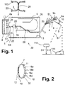
- a laying system 30 for producing an in Fig. 1 The indicated cable harness 2 has a laying table 1, a control and evaluation device 8 which represents part of the laying table 1 or is arranged externally to the laying table 1, and a mobile unit 10.
- the wire harness 2, e.g. B. a cable harness is composed of several individual cables 3, each cable 3 having one or more electrical lines 4, optionally together with optical lines.
- the laying table 1 has a laying surface 5, in or on which a display device 6 is provided.
- the laying surface 5 can be formed by the display device 6 itself.
- the mobile unit 10 and the control and evaluation device 8 together form a detection device, which together with the laying table 1 thus forms the laying system 30.
- a user 9 slips on a portable mobile unit 10 according to an embodiment of the invention, which is designed here with a bracelet 7 (arm strap) as a fastening device and z. B. is placed over the user's wrist 9a so that it is in contact with the user's skin.
- the user takes a cable 3 with a connector 20 provided on a first end 3a of the cable 3 and inserts the connector 20 into a connector holder 22 (plug-in module) which is provided on the installation table 5 and is connected to the control and evaluation device 8, and takes a line 4 of the cable 3rd
- Fig. 1 also a stationary unit 110 with transmission of the detection frequency signals S1 to the user 9, and / or z. B. a conductive underground 1 12, z. B. floor can be provided, via which the detection frequency signals S1 to the user, for. B. clothing such. B. a shoe 111 of the user 9 are transmitted.
- the user 9 picks up the detection frequency signals S1 from a conductive environment and forwards them, or they are transmitted wirelessly to a converter on the body of the user for conversion into the capacitive signals.
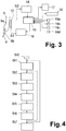
- the mobile unit 10 also has a display device 32, e.g. with multiple signal lights to indicate a status or multiple status information such as B. "Not ready for use, ready for use, in (transmission) operation, battery weak".
- the functionality of the control units 18a, 18b, 18c, 18d can advantageously be freely programmable.
- the capacitive coupler 12 outputs capacitive detection frequency signals S1 via the body of the user 9. If the user 9 according to Fig. 1 touches a line 4 of the cable 3 with his fingers 9b - one touch is sufficient here. B. the electrical insulation / stranded wire on line 4 - again enables capacitive data transmission from fingers 9b to line 4, so that signals S1 can be transmitted via line 4 through cable 3.
- the plug holder 22 (plug-in module) is connected to a communication interface 24 of the control and evaluation device 8, which thus receives and demodulates the detection frequency signals S1, and is also designed accordingly for outputting two capacitive frequency signals S2, which are returned via the Connector bracket 22, the connector 20, the line 4 and the user 9 are transmitted to the mobile unit 10.
- the control and evaluation device 8 is still - z. B. via a data interface - connected to the display device 6 to display signals Output S3, which are used by the display device 6 for the two-dimensional optical display of a laying path 26.
- control and evaluation device 8 Since the user 9 touches a line 4 of the cable 3 with the fingers 9b of the hand on which the mobile unit 10 is held as a bracelet, data communication is started, in which the mobile unit 10 sends first frequency signals S1 to the control and outputs evaluation device 8.
- the control and evaluation device 8 thus recognizes the cable 3 and accesses an internal - or external - memory 8a with current data about the cable harness 2 to be formed. From this, the control and evaluation device 8 forms display signals S3, which it outputs to the display device 6.
- the display device 6 is here, for. B. as a two-dimensional display unit, d. H. Display matrix, e.g. Example, as an LED or LCD panel, which directly indicates the installation path provided for the present cable 3.
- the user thus recognizes the current laying path 26 and can lay the cable 3 currently selected by him according to the laying path 26 on the laying table 1, the cable 3 advantageously in each case provided in receptacles 28, such as. B. clamps, etc., is firmly received, so that a cable harness 2 or wiring harness is formed with firmly connected individual cables 3, which are laid in predetermined installation paths 26.
- the user can the second end 3b of the cable 3 with the still open or individual lines 4 z. B. provided with a second connector 120, and in turn plug the second connector 120 into a suitable connector holder, which is indicated to him by the installation path 26.
- the user 9 selects the next cable 3, plugs its plug 20 into the plug holder 22 suitable for this purpose and touches a line 4 with his fingers 9b, so that the suitable routing path 26 is shown again by the control and evaluation device 8 becomes.
- the wire harness 2 or wire harness is successively formed from the individual cables 3.
- the user ID stored in the memory 17 of the mobile unit 10 enables the mobile unit to be uniquely assigned to the user.
- multi-user operation or multi-person operation is possible, in which a plurality of users 9 thus form the cable harness 2, the mobile units 10 advantageously output different detection frequency signals S1, the differentiation using different frequencies, e.g. B. in the frequency band from 2 to 10 MHz, so the frequency signals S1 do not interfere.
- additional information about the cable 3 can be displayed to the user via the display device 6, e.g. B. the number of lines 4.
- a cable harness 2 takes place through natural movements, in which a user grips lines 4 of a cable 3 with the fingers 9b of the relevant hand, provided on the mobile unit 10, and immediately visually takes the laying path 26, possibly also further ones Information that is displayed.
- Fig. 5 shows an embodiment of the signal demodulation and signal processing by the control and evaluation device 8: a plurality of plug holders 22, which are referred to here as 22a, 22b, 22c, 22d, each receive a cable 3 with plug 22, which, as described above, receive detection frequency signals S1 of the mobile unit.
- the connector brackets 22a to 22d are connected to the communication interface 24, which is designed here as a demodulator and multiplexer and z.
- B. scanned the connector holders 22, the detection frequency signals S1 demodulated and multiplexed to the control and evaluation device 8, which then uses data from the internal or external storage device 8a as described and outputs the display signals S3.
- the plug holders 22 and the display device 6 are part of the laying table 1; the control and evaluation device 8 together with the communication interface 24 can be designed externally or as part of the installation table 1.
Landscapes
- Engineering & Computer Science (AREA)
- Computer Networks & Wireless Communication (AREA)
- Signal Processing (AREA)
- Manufacturing & Machinery (AREA)
- Testing Of Short-Circuits, Discontinuities, Leakage, Or Incorrect Line Connections (AREA)
- Telephone Function (AREA)
- Electric Cable Installation (AREA)
- Length Measuring Devices With Unspecified Measuring Means (AREA)
- Looms (AREA)
Claims (15)
- Dispositif de détection (8 ; 10, 11) pour un système de pose (30) servant à former un faisceau de câbles (2), le dispositif de détection présentant :une unité (10, 110) avec un coupleur capacitif (12) servant à coupler des signaux de fréquence de reconnaissance (S1) dans le corps de l'utilisateur (9), un dispositif de commande et d'évaluation (8) servant à émettre des signaux d'affichage (S3) vers un dispositif d'affichage (6),le dispositif de commande et d'évaluation (8) étant conçu pour la communication de données avec l'unité (10, 110) via des supports de connecteurs (22) et un câble (3) raccordé aux supports de connecteurs (22), le dispositif de commande et d'évaluation (8) étant adapté pour détecter le câble (3) raccordé et/ou des conducteurs individuels (4) du câble (3), et le dispositif de commande et d'évaluation (8) étant adapté pour émettre des signaux d'affichage (S3) vers le dispositif d'affichage (6) via un support de connecteur (22) suite à la réception d'un signal de fréquence de reconnaissance (S1) par l'unité (10, 110) pour afficher un trajet de pose (26) pour le câble (3) raccordé et/ou des conducteurs individuels (4) du câble (3).
- Dispositif de détection (8, 10) suivant la revendication 1, caractérisé en ce que l'unité est conçue comme unité mobile (10) avec un dispositif de fixation (7) permettant la fixation sur l'utilisateur (9), de préférence avec un accumulateur d'énergie (11), par exemple une batterie ou un accumulateur.
- Dispositif de détection suivant la revendication 2, caractérisé en ce que l'unité mobile (10) est conçue comme bracelet fonctionnel destiné à être fixé sur une main, un poignet ou un bras de l'utilisateur (9).
- Dispositif de détection (8, 110) suivant la revendication 1, caractérisé en ce que l'unité est conçue comme unité stationnaire (110) pour la transmission du signal de fréquence de reconnaissance (S1) à l'utilisateur (9), en particulier avec un environnement conducteur, par exemple un fond conducteur (112) pour la transmission à l'utilisateur (9).
- Dispositif de détection (8, 110) suivant une des revendications précédentes, caractérisé en ce que le dispositif de commande et d'évaluation (8) présente un dispositif de mémoire (8a), dans lequel sont mémorisées des données relatives aux connecteurs (3), les trajets de pose associés (26) et les signaux d'affichage (S3), ainsi que des données relatives aux identifiants utilisateur des unités (10, 110) et des signaux de fréquence de reconnaissance (S1) de plusieurs unités (10, 110).
- Dispositif de détection suivant une des revendications précédentes, caractérisé en ce que le dispositif de commande et d'évaluation (8) émet automatiquement les signaux d'affichage (S3) lorsqu'un signal de fréquence de reconnaissance (S1) est reçu.
- Dispositif de détection suivant une des revendications précédentes, caractérisé en ce que le dispositif de commande et d'évaluation (8) est adapté pour balayer la pluralité des supports de connecteurs (22) et comporte un dispositif de multiplexage (24), en particulier en tant que partie d'une interface de données (24) pour le multiplexage des signaux de fréquence de reconnaissance (S1) ou de signaux de fréquence de reconnaissance démodulés (S1).
- Dispositif de détection suivant une des revendications précédentes, caractérisé en ce que l'unité (10, 110) présente :
un modulateur (16) pour la génération des signaux de fréquence de reconnaissance (S1) et l'émission vers le coupleur capacitif (12), et une unité de commande périphérique (15) pour le pilotage du modulateur (16). - Dispositif de détection (8 ; 10, 110) suivant la revendication 8, caractérisé en ce que l'unité (10, 110) présente en plus :une mémoire (17), par exemple une mémoire interne (17) pour la mémorisation d'un identifiant utilisateur,au moins un dispositif d'actionnement (18a, b, c, d) de préférence programmable, par exemple, des surfaces d'actionnement pour l'actionnement par l'utilisateur et l'activation de fonctions.
- Dispositif de détection (8 ; 10, 110) suivant la revendication 8 ou 9, caractérisé en ce que l'unité (10, 110) comporte, en plus, un dispositif d'affichage (32) pour l'affichage d'au moins un état de fonctionnement, par exemple, un état de fonctionnement pour l'indication d'un fonctionnement et/ou un état de fonctionnement pour l'indication d'une disponibilité opérationnelle, et/ou pour l'indication d'un état d'émission et/ou pour l'indication d'un état de l'accumulateur d'énergie.
- Dispositif de détection (8; 10, 110) suivant une des revendications 8 à 10, caractérisé en ce que l'unité (10, 110) présente, en plus, un démodulateur (14) pour la démodulation de seconds signaux de fréquence (S2) reçus par le dispositif de commande et d'évaluation (8), pour une communication de données bidirectionnelle entre le dispositif de commande et d'évaluation (8) et l'unité de commande périphérique (15) via le corps de l'utilisateur (9) et un conducteur (4) d'un câble (3).
- Système de pose (30) pour la formation de faisceaux de câbles (2), le système présentant :un dispositif de détection suivant une des revendications précédentes,plusieurs supports de connecteurs (22) destinés à recevoir respectivement un connecteur (20) d'un câble (3) ;un dispositif d'affichage (6) pour la réception des signaux d'affichage (S3) et un affichage bidimensionnel des trajets de pose (26),le dispositif d'affichage (6) comportant un affichage bidimensionnel qui forme une surface de pose (5) pour poser les câbles (3) et/ou les conducteurs (4) du câble (3) le long d'un trajet de pose bidimensionnel (26), etles supports de connecteurs (22) et le dispositif d'affichage (6) étant reliés entre eux via le dispositif de commande et d'évaluation (8).
- Procédé de fabrication d'un faisceau de câbles (2) comportant au moins les étapes suivantes qui consistent à :fournir une table de pose (1) avec un dispositif d'affichage (6) pour l'affichage de trajets de pose (26), un dispositif de commande et d'évaluation (8), des supports de connecteurs (22) raccordés au dispositif de commande et d'évaluation (8) et une unité destinée à émettre des signaux de fréquence de reconnaissance (S1) (St0),brancher un câble (3) à l'aide de son connecteur (20), raccordé à la première extrémité (3a) de celui-ci, à un support de connecteur (22) de la table de pose (1) (St1),établir une liaison de communication entre l'unité (10, 110) et le dispositif de commande et d'évaluation (8) par l'intermédiaire d'un couplage capacitif via l'utilisateur (9) et d'un conducteur (4) du câble (3) saisi par l'utilisateur, du connecteur (20) et du support de connecteur (22), en émettant des signaux de fréquence de reconnaissance (S1) depuis l'unité (10, 110) vers le dispositif de commande et d'évaluation (8) (St2),détecter le câble (3) raccordé et/ou des conducteur individuels (4) du câble (3) au moyen du dispositif de commande et d'évaluation (8), des données mémorisées relatives aux câbles (3) étant lues, (St4),émettre des signaux d'affichage (S3) depuis le dispositif de commande et d'évaluation (8) vers le dispositif d'affichage (6) et l'affichage d'un trajet de pose (26) pour le câble (3) et/ou des conducteurs individuels (4) du câble (3) sur le dispositif d'affichage (6) (St5),finir le câble (3) (St6),répéter, en établissant une nouvelle liaison de communication entre l'unité (10, 110) et un autre câble (3), les étapes à partir du branchement d'un câble (3) jusqu'à ce que le faisceau de câble (2) soit formé.
- Procédé suivant la revendication 13, caractérisé en ce que les étapes sont successivement répétées pour les conducteurs individuels (4) du câble (3) à partir de l'établissement d'une liaison de communication (St2) lors de la pose de conducteurs individuels (4) du câble (3).
- Procédé suivant la revendication 13 ou 14, caractérisé en ce qu'à réception de plusieurs premiers signaux de fréquence (S1) de plusieurs unités (10, 110) et émission associée de signaux d'affichage (S3), un service multi-utilisateur est exécutable ou exécuté.
Priority Applications (1)
| Application Number | Priority Date | Filing Date | Title |
|---|---|---|---|
| PL17749678T PL3494580T3 (pl) | 2016-08-03 | 2017-07-28 | Urządzenie detekcyjne dla systemu układania wiązek kablowych |
Applications Claiming Priority (2)
| Application Number | Priority Date | Filing Date | Title |
|---|---|---|---|
| EP16182603.7A EP3279903A1 (fr) | 2016-08-03 | 2016-08-03 | Dispositif de detection d'un systeme de deplacement de faisceau de cables |
| PCT/EP2017/069123 WO2018024621A1 (fr) | 2016-08-03 | 2017-07-28 | Dispositif de détection de système de pose de faisceau de câble |
Publications (2)
| Publication Number | Publication Date |
|---|---|
| EP3494580A1 EP3494580A1 (fr) | 2019-06-12 |
| EP3494580B1 true EP3494580B1 (fr) | 2020-04-29 |
Family
ID=56893676
Family Applications (2)
| Application Number | Title | Priority Date | Filing Date |
|---|---|---|---|
| EP16182603.7A Withdrawn EP3279903A1 (fr) | 2016-08-03 | 2016-08-03 | Dispositif de detection d'un systeme de deplacement de faisceau de cables |
| EP17749678.3A Active EP3494580B1 (fr) | 2016-08-03 | 2017-07-28 | Dispositif de detection d'un systeme de deplacement de faisceau de cables |
Family Applications Before (1)
| Application Number | Title | Priority Date | Filing Date |
|---|---|---|---|
| EP16182603.7A Withdrawn EP3279903A1 (fr) | 2016-08-03 | 2016-08-03 | Dispositif de detection d'un systeme de deplacement de faisceau de cables |
Country Status (9)
| Country | Link |
|---|---|
| EP (2) | EP3279903A1 (fr) |
| CN (1) | CN109690700B (fr) |
| ES (1) | ES2808335T3 (fr) |
| HU (1) | HUE050280T2 (fr) |
| MA (1) | MA45847B1 (fr) |
| MX (1) | MX2019001353A (fr) |
| PL (1) | PL3494580T3 (fr) |
| PT (1) | PT3494580T (fr) |
| WO (1) | WO2018024621A1 (fr) |
Families Citing this family (2)
| Publication number | Priority date | Publication date | Assignee | Title |
|---|---|---|---|---|
| CN112292737B (zh) * | 2018-06-18 | 2023-04-04 | 利萨·德雷克塞迈尔有限责任公司 | 装配辅助方法和装配装置 |
| CN111914374A (zh) * | 2019-06-24 | 2020-11-10 | 中车大同电力机车有限公司 | 屏柜的预布线系统 |
Family Cites Families (8)
| Publication number | Priority date | Publication date | Assignee | Title |
|---|---|---|---|---|
| FR2808374A1 (fr) * | 2000-04-27 | 2001-11-02 | Labinal | Installation de fabrication d'un faisceau de cables |
| US20030030206A1 (en) * | 2001-07-23 | 2003-02-13 | Yazaki Corporation | Wire harness arranging-purpose wire holding member and wire harness arranging-method |
| ES2443265B1 (es) * | 2012-08-16 | 2014-11-13 | Eads Construcciones Aeronauticas, S.A. | Banco de fabricación o verificación de mazos eléctricos |
| JP2014192113A (ja) * | 2013-03-28 | 2014-10-06 | Sumitomo Wiring Syst Ltd | ワイヤーハーネスの製造方法 |
| FR3005375B1 (fr) * | 2013-05-06 | 2017-01-13 | Laselec | Support de production de harnais de cables |
| JP2015076912A (ja) * | 2013-10-07 | 2015-04-20 | パナソニックIpマネジメント株式会社 | 配線容量表示システム |
| US9818179B2 (en) * | 2013-12-05 | 2017-11-14 | Bombardier Transportation Gmbh | Method for manufacturing a wire harness |
| JP6213437B2 (ja) * | 2014-09-25 | 2017-10-18 | 住友電装株式会社 | ワイヤーハーネスの製造方法及びワイヤーハーネス製造用装置 |
-
2016
- 2016-08-03 EP EP16182603.7A patent/EP3279903A1/fr not_active Withdrawn
-
2017
- 2017-07-28 MA MA45847A patent/MA45847B1/fr unknown
- 2017-07-28 HU HUE17749678A patent/HUE050280T2/hu unknown
- 2017-07-28 PT PT177496783T patent/PT3494580T/pt unknown
- 2017-07-28 MX MX2019001353A patent/MX2019001353A/es unknown
- 2017-07-28 PL PL17749678T patent/PL3494580T3/pl unknown
- 2017-07-28 CN CN201780049335.4A patent/CN109690700B/zh active Active
- 2017-07-28 EP EP17749678.3A patent/EP3494580B1/fr active Active
- 2017-07-28 ES ES17749678T patent/ES2808335T3/es active Active
- 2017-07-28 WO PCT/EP2017/069123 patent/WO2018024621A1/fr not_active Ceased
Non-Patent Citations (1)
| Title |
|---|
| None * |
Also Published As
| Publication number | Publication date |
|---|---|
| MX2019001353A (es) | 2019-06-03 |
| CN109690700B (zh) | 2020-07-24 |
| ES2808335T3 (es) | 2021-02-26 |
| CN109690700A (zh) | 2019-04-26 |
| PL3494580T3 (pl) | 2020-11-16 |
| WO2018024621A1 (fr) | 2018-02-08 |
| PT3494580T (pt) | 2020-08-03 |
| HUE050280T2 (hu) | 2020-12-28 |
| EP3279903A1 (fr) | 2018-02-07 |
| EP3494580A1 (fr) | 2019-06-12 |
| MA45847B1 (fr) | 2020-07-29 |
Similar Documents
| Publication | Publication Date | Title |
|---|---|---|
| DE102006050534B4 (de) | Leitungssystem für ein Luftfahrzeug, insbesondere ein Flugzeug | |
| EP2842899B1 (fr) | Ruban de mesure pour un ascenseur | |
| DE102007046385A1 (de) | Optischer Fasersensor mit elektrischen Anschlüssen | |
| EP2338207B1 (fr) | Antenne pour balise rfid | |
| EP3494580B1 (fr) | Dispositif de detection d'un systeme de deplacement de faisceau de cables | |
| DE102011005302A1 (de) | Verschleißerkennungssystem und Verfahren | |
| DE102006014021B4 (de) | Stromleitungs-Kommunikationssystem | |
| DE102010007347A1 (de) | Tragbare Überwachungsvorrichtung und Verfahren zum Betreiben derselben | |
| WO2012019760A1 (fr) | Appareil ecg à main | |
| DE102017223665A1 (de) | Elektrisches Batteriemodul | |
| EP2132870A2 (fr) | Dispositif de moteur | |
| EP0596344A1 (fr) | Dispositif de raccordement pour électrodes de l'électro-cardiogramme | |
| EP2274797B1 (fr) | Cable electrique ainsi que procede et dispositif pour sa production | |
| DE102009048617A1 (de) | Diagnosesystem für Kraftfahrzeuge | |
| DE112019004681T5 (de) | Verdrahtungselement | |
| DE102019127468A1 (de) | Chirurgische Vorrichtung mit integrierter RFID-Ausleseantenne | |
| DE102018220483A1 (de) | Ladesystem für ein elektrisch antreibbares Fahrzeug, Verfahren zum Betreiben eines Ladesystems | |
| DE10037969C2 (de) | Verfahren zur Erkennung einer flexiblen Vernetzung von Baugruppen bei beliebiger Netztopologie sowie zum Informationsaustausch zwischen solchen Baugruppen | |
| DE102014212734A1 (de) | Verfahren und Vorrichtung zur Herstellung einer Innenbeleuchtung für ein Fahrzeug sowie Innenbeleuchtung | |
| DE102017007121A1 (de) | Verfahren zum Betrieb eines automatischen Parkhauses | |
| DE112022001194T5 (de) | Verkabelungsbauteil | |
| DE102010043029A1 (de) | Auswahlschaltung für eine Elektrodenanordnung sowie Verfahren zum Betrieb und zum Herstellen einer Elektrodenanordnung | |
| DE102021127570A1 (de) | Kabel mit haptisch ertastbarem Verdrehindikator und Verfahren zur torsionsfreien Verlegung eines solchen Kabels | |
| WO2008119311A1 (fr) | Dispositif de détection et de transmission d'impulsions électriques | |
| DE102007028643A1 (de) | Reiheneinbaugeräte und Reiheneinbaugeräteensemble |
Legal Events
| Date | Code | Title | Description |
|---|---|---|---|
| STAA | Information on the status of an ep patent application or granted ep patent |
Free format text: STATUS: UNKNOWN |
|
| STAA | Information on the status of an ep patent application or granted ep patent |
Free format text: STATUS: THE INTERNATIONAL PUBLICATION HAS BEEN MADE |
|
| PUAI | Public reference made under article 153(3) epc to a published international application that has entered the european phase |
Free format text: ORIGINAL CODE: 0009012 |
|
| STAA | Information on the status of an ep patent application or granted ep patent |
Free format text: STATUS: REQUEST FOR EXAMINATION WAS MADE |
|
| 17P | Request for examination filed |
Effective date: 20190115 |
|
| AK | Designated contracting states |
Kind code of ref document: A1 Designated state(s): AL AT BE BG CH CY CZ DE DK EE ES FI FR GB GR HR HU IE IS IT LI LT LU LV MC MK MT NL NO PL PT RO RS SE SI SK SM TR |
|
| AX | Request for extension of the european patent |
Extension state: BA ME |
|
| DAX | Request for extension of the european patent (deleted) | ||
| RAV | Requested validation state of the european patent: fee paid |
Extension state: MA Effective date: 20190115 |
|
| GRAP | Despatch of communication of intention to grant a patent |
Free format text: ORIGINAL CODE: EPIDOSNIGR1 |
|
| STAA | Information on the status of an ep patent application or granted ep patent |
Free format text: STATUS: GRANT OF PATENT IS INTENDED |
|
| INTG | Intention to grant announced |
Effective date: 20191205 |
|
| GRAS | Grant fee paid |
Free format text: ORIGINAL CODE: EPIDOSNIGR3 |
|
| GRAA | (expected) grant |
Free format text: ORIGINAL CODE: 0009210 |
|
| STAA | Information on the status of an ep patent application or granted ep patent |
Free format text: STATUS: THE PATENT HAS BEEN GRANTED |
|
| AK | Designated contracting states |
Kind code of ref document: B1 Designated state(s): AL AT BE BG CH CY CZ DE DK EE ES FI FR GB GR HR HU IE IS IT LI LT LU LV MC MK MT NL NO PL PT RO RS SE SI SK SM TR |
|
| REG | Reference to a national code |
Ref country code: GB Ref legal event code: FG4D Free format text: NOT ENGLISH |
|
| REG | Reference to a national code |
Ref country code: CH Ref legal event code: EP |
|
| REG | Reference to a national code |
Ref country code: AT Ref legal event code: REF Ref document number: 1264523 Country of ref document: AT Kind code of ref document: T Effective date: 20200515 |
|
| REG | Reference to a national code |
Ref country code: DE Ref legal event code: R096 Ref document number: 502017005060 Country of ref document: DE |
|
| REG | Reference to a national code |
Ref country code: IE Ref legal event code: FG4D Free format text: LANGUAGE OF EP DOCUMENT: GERMAN |
|
| REG | Reference to a national code |
Ref country code: MA Ref legal event code: VAGR Ref document number: 45847 Country of ref document: MA Kind code of ref document: B1 |
|
| REG | Reference to a national code |
Ref country code: PT Ref legal event code: SC4A Ref document number: 3494580 Country of ref document: PT Date of ref document: 20200803 Kind code of ref document: T Free format text: AVAILABILITY OF NATIONAL TRANSLATION Effective date: 20200728 |
|
| REG | Reference to a national code |
Ref country code: NL Ref legal event code: MP Effective date: 20200429 |
|
| REG | Reference to a national code |
Ref country code: LT Ref legal event code: MG4D |
|
| PG25 | Lapsed in a contracting state [announced via postgrant information from national office to epo] |
Ref country code: FI Free format text: LAPSE BECAUSE OF FAILURE TO SUBMIT A TRANSLATION OF THE DESCRIPTION OR TO PAY THE FEE WITHIN THE PRESCRIBED TIME-LIMIT Effective date: 20200429 Ref country code: SE Free format text: LAPSE BECAUSE OF FAILURE TO SUBMIT A TRANSLATION OF THE DESCRIPTION OR TO PAY THE FEE WITHIN THE PRESCRIBED TIME-LIMIT Effective date: 20200429 Ref country code: NO Free format text: LAPSE BECAUSE OF FAILURE TO SUBMIT A TRANSLATION OF THE DESCRIPTION OR TO PAY THE FEE WITHIN THE PRESCRIBED TIME-LIMIT Effective date: 20200729 Ref country code: IS Free format text: LAPSE BECAUSE OF FAILURE TO SUBMIT A TRANSLATION OF THE DESCRIPTION OR TO PAY THE FEE WITHIN THE PRESCRIBED TIME-LIMIT Effective date: 20200829 Ref country code: LT Free format text: LAPSE BECAUSE OF FAILURE TO SUBMIT A TRANSLATION OF THE DESCRIPTION OR TO PAY THE FEE WITHIN THE PRESCRIBED TIME-LIMIT Effective date: 20200429 Ref country code: GR Free format text: LAPSE BECAUSE OF FAILURE TO SUBMIT A TRANSLATION OF THE DESCRIPTION OR TO PAY THE FEE WITHIN THE PRESCRIBED TIME-LIMIT Effective date: 20200730 |
|
| PG25 | Lapsed in a contracting state [announced via postgrant information from national office to epo] |
Ref country code: BG Free format text: LAPSE BECAUSE OF FAILURE TO SUBMIT A TRANSLATION OF THE DESCRIPTION OR TO PAY THE FEE WITHIN THE PRESCRIBED TIME-LIMIT Effective date: 20200729 Ref country code: RS Free format text: LAPSE BECAUSE OF FAILURE TO SUBMIT A TRANSLATION OF THE DESCRIPTION OR TO PAY THE FEE WITHIN THE PRESCRIBED TIME-LIMIT Effective date: 20200429 Ref country code: HR Free format text: LAPSE BECAUSE OF FAILURE TO SUBMIT A TRANSLATION OF THE DESCRIPTION OR TO PAY THE FEE WITHIN THE PRESCRIBED TIME-LIMIT Effective date: 20200429 Ref country code: LV Free format text: LAPSE BECAUSE OF FAILURE TO SUBMIT A TRANSLATION OF THE DESCRIPTION OR TO PAY THE FEE WITHIN THE PRESCRIBED TIME-LIMIT Effective date: 20200429 |
|
| REG | Reference to a national code |
Ref country code: HU Ref legal event code: AG4A Ref document number: E050280 Country of ref document: HU |
|
| PG25 | Lapsed in a contracting state [announced via postgrant information from national office to epo] |
Ref country code: NL Free format text: LAPSE BECAUSE OF FAILURE TO SUBMIT A TRANSLATION OF THE DESCRIPTION OR TO PAY THE FEE WITHIN THE PRESCRIBED TIME-LIMIT Effective date: 20200429 Ref country code: AL Free format text: LAPSE BECAUSE OF FAILURE TO SUBMIT A TRANSLATION OF THE DESCRIPTION OR TO PAY THE FEE WITHIN THE PRESCRIBED TIME-LIMIT Effective date: 20200429 |
|
| PG25 | Lapsed in a contracting state [announced via postgrant information from national office to epo] |
Ref country code: DK Free format text: LAPSE BECAUSE OF FAILURE TO SUBMIT A TRANSLATION OF THE DESCRIPTION OR TO PAY THE FEE WITHIN THE PRESCRIBED TIME-LIMIT Effective date: 20200429 Ref country code: IT Free format text: LAPSE BECAUSE OF FAILURE TO SUBMIT A TRANSLATION OF THE DESCRIPTION OR TO PAY THE FEE WITHIN THE PRESCRIBED TIME-LIMIT Effective date: 20200429 Ref country code: SM Free format text: LAPSE BECAUSE OF FAILURE TO SUBMIT A TRANSLATION OF THE DESCRIPTION OR TO PAY THE FEE WITHIN THE PRESCRIBED TIME-LIMIT Effective date: 20200429 Ref country code: EE Free format text: LAPSE BECAUSE OF FAILURE TO SUBMIT A TRANSLATION OF THE DESCRIPTION OR TO PAY THE FEE WITHIN THE PRESCRIBED TIME-LIMIT Effective date: 20200429 |
|
| REG | Reference to a national code |
Ref country code: DE Ref legal event code: R097 Ref document number: 502017005060 Country of ref document: DE |
|
| PG25 | Lapsed in a contracting state [announced via postgrant information from national office to epo] |
Ref country code: MC Free format text: LAPSE BECAUSE OF FAILURE TO SUBMIT A TRANSLATION OF THE DESCRIPTION OR TO PAY THE FEE WITHIN THE PRESCRIBED TIME-LIMIT Effective date: 20200429 Ref country code: SK Free format text: LAPSE BECAUSE OF FAILURE TO SUBMIT A TRANSLATION OF THE DESCRIPTION OR TO PAY THE FEE WITHIN THE PRESCRIBED TIME-LIMIT Effective date: 20200429 |
|
| REG | Reference to a national code |
Ref country code: ES Ref legal event code: FG2A Ref document number: 2808335 Country of ref document: ES Kind code of ref document: T3 Effective date: 20210226 Ref country code: CH Ref legal event code: PL |
|
| PLBE | No opposition filed within time limit |
Free format text: ORIGINAL CODE: 0009261 |
|
| STAA | Information on the status of an ep patent application or granted ep patent |
Free format text: STATUS: NO OPPOSITION FILED WITHIN TIME LIMIT |
|
| 26N | No opposition filed |
Effective date: 20210201 |
|
| REG | Reference to a national code |
Ref country code: BE Ref legal event code: MM Effective date: 20200731 |
|
| PG25 | Lapsed in a contracting state [announced via postgrant information from national office to epo] |
Ref country code: FR Free format text: LAPSE BECAUSE OF NON-PAYMENT OF DUE FEES Effective date: 20200731 Ref country code: CH Free format text: LAPSE BECAUSE OF NON-PAYMENT OF DUE FEES Effective date: 20200731 Ref country code: LI Free format text: LAPSE BECAUSE OF NON-PAYMENT OF DUE FEES Effective date: 20200731 Ref country code: LU Free format text: LAPSE BECAUSE OF NON-PAYMENT OF DUE FEES Effective date: 20200728 |
|
| PG25 | Lapsed in a contracting state [announced via postgrant information from national office to epo] |
Ref country code: BE Free format text: LAPSE BECAUSE OF NON-PAYMENT OF DUE FEES Effective date: 20200731 Ref country code: SI Free format text: LAPSE BECAUSE OF FAILURE TO SUBMIT A TRANSLATION OF THE DESCRIPTION OR TO PAY THE FEE WITHIN THE PRESCRIBED TIME-LIMIT Effective date: 20200429 |
|
| VSFP | Annual fee paid to validation state [announced via postgrant information from national office to epo] |
Ref country code: MA Payment date: 20200827 Year of fee payment: 4 |
|
| PG25 | Lapsed in a contracting state [announced via postgrant information from national office to epo] |
Ref country code: IE Free format text: LAPSE BECAUSE OF NON-PAYMENT OF DUE FEES Effective date: 20200728 |
|
| GBPC | Gb: european patent ceased through non-payment of renewal fee |
Effective date: 20210728 |
|
| PG25 | Lapsed in a contracting state [announced via postgrant information from national office to epo] |
Ref country code: GB Free format text: LAPSE BECAUSE OF NON-PAYMENT OF DUE FEES Effective date: 20210728 |
|
| PG25 | Lapsed in a contracting state [announced via postgrant information from national office to epo] |
Ref country code: TR Free format text: LAPSE BECAUSE OF FAILURE TO SUBMIT A TRANSLATION OF THE DESCRIPTION OR TO PAY THE FEE WITHIN THE PRESCRIBED TIME-LIMIT Effective date: 20200429 Ref country code: MT Free format text: LAPSE BECAUSE OF FAILURE TO SUBMIT A TRANSLATION OF THE DESCRIPTION OR TO PAY THE FEE WITHIN THE PRESCRIBED TIME-LIMIT Effective date: 20200429 Ref country code: CY Free format text: LAPSE BECAUSE OF FAILURE TO SUBMIT A TRANSLATION OF THE DESCRIPTION OR TO PAY THE FEE WITHIN THE PRESCRIBED TIME-LIMIT Effective date: 20200429 |
|
| PG25 | Lapsed in a contracting state [announced via postgrant information from national office to epo] |
Ref country code: MK Free format text: LAPSE BECAUSE OF FAILURE TO SUBMIT A TRANSLATION OF THE DESCRIPTION OR TO PAY THE FEE WITHIN THE PRESCRIBED TIME-LIMIT Effective date: 20200429 |
|
| REG | Reference to a national code |
Ref country code: AT Ref legal event code: MM01 Ref document number: 1264523 Country of ref document: AT Kind code of ref document: T Effective date: 20220728 |
|
| PG25 | Lapsed in a contracting state [announced via postgrant information from national office to epo] |
Ref country code: AT Free format text: LAPSE BECAUSE OF NON-PAYMENT OF DUE FEES Effective date: 20220728 |
|
| PGFP | Annual fee paid to national office [announced via postgrant information from national office to epo] |
Ref country code: PT Payment date: 20250625 Year of fee payment: 9 |
|
| PGFP | Annual fee paid to national office [announced via postgrant information from national office to epo] |
Ref country code: HU Payment date: 20250728 Year of fee payment: 9 |
|
| PGFP | Annual fee paid to national office [announced via postgrant information from national office to epo] |
Ref country code: ES Payment date: 20250819 Year of fee payment: 9 |
|
| PGFP | Annual fee paid to national office [announced via postgrant information from national office to epo] |
Ref country code: DE Payment date: 20250911 Year of fee payment: 9 |
|
| PGFP | Annual fee paid to national office [announced via postgrant information from national office to epo] |
Ref country code: PL Payment date: 20250717 Year of fee payment: 9 |
|
| PGFP | Annual fee paid to national office [announced via postgrant information from national office to epo] |
Ref country code: CZ Payment date: 20250715 Year of fee payment: 9 |
|
| PGFP | Annual fee paid to national office [announced via postgrant information from national office to epo] |
Ref country code: RO Payment date: 20250724 Year of fee payment: 9 |
|
| VSFP | Annual fee paid to validation state [announced via postgrant information from national office to epo] |
Ref country code: MA Payment date: 20230726 Year of fee payment: 7 |
|
| VSFP | Annual fee paid to validation state [announced via postgrant information from national office to epo] |
Ref country code: MA Payment date: 20220725 Year of fee payment: 6 Ref country code: MA Payment date: 20210907 Year of fee payment: 5 |
|
| VSFP | Annual fee paid to validation state [announced via postgrant information from national office to epo] |
Ref country code: MA Payment date: 20240708 Year of fee payment: 8 |
|
| VSFP | Annual fee paid to validation state [announced via postgrant information from national office to epo] |
Ref country code: MA Payment date: 20200827 Year of fee payment: 4 Ref country code: MA Payment date: 20250731 Year of fee payment: 9 |