EP3494580B1 - Detection device for a cable strand laying system - Google Patents
Detection device for a cable strand laying system Download PDFInfo
- Publication number
- EP3494580B1 EP3494580B1 EP17749678.3A EP17749678A EP3494580B1 EP 3494580 B1 EP3494580 B1 EP 3494580B1 EP 17749678 A EP17749678 A EP 17749678A EP 3494580 B1 EP3494580 B1 EP 3494580B1
- Authority
- EP
- European Patent Office
- Prior art keywords
- cable
- user
- control
- unit
- display
- Prior art date
- Legal status (The legal status is an assumption and is not a legal conclusion. Google has not performed a legal analysis and makes no representation as to the accuracy of the status listed.)
- Active
Links
Images

Classifications
-
- H—ELECTRICITY
- H01—ELECTRIC ELEMENTS
- H01B—CABLES; CONDUCTORS; INSULATORS; SELECTION OF MATERIALS FOR THEIR CONDUCTIVE, INSULATING OR DIELECTRIC PROPERTIES
- H01B13/00—Apparatus or processes specially adapted for manufacturing conductors or cables
- H01B13/012—Apparatus or processes specially adapted for manufacturing conductors or cables for manufacturing wire harnesses
- H01B13/01218—Apparatus or processes specially adapted for manufacturing conductors or cables for manufacturing wire harnesses the wires being disposed by hand
- H01B13/01227—Apparatus or processes specially adapted for manufacturing conductors or cables for manufacturing wire harnesses the wires being disposed by hand using a layout board
-
- H—ELECTRICITY
- H04—ELECTRIC COMMUNICATION TECHNIQUE
- H04B—TRANSMISSION
- H04B13/00—Transmission systems characterised by the medium used for transmission, not provided for in groups H04B3/00 - H04B11/00
- H04B13/005—Transmission systems in which the medium consists of the human body
-
- G—PHYSICS
- G06—COMPUTING OR CALCULATING; COUNTING
- G06F—ELECTRIC DIGITAL DATA PROCESSING
- G06F3/00—Input arrangements for transferring data to be processed into a form capable of being handled by the computer; Output arrangements for transferring data from processing unit to output unit, e.g. interface arrangements
- G06F3/01—Input arrangements or combined input and output arrangements for interaction between user and computer
- G06F3/011—Arrangements for interaction with the human body, e.g. for user immersion in virtual reality
Definitions
- the invention relates to a detection device for a cable harness laying system, such a laying system and a method for producing a cable harness.
- Cable harnesses e.g. B. harnesses are used in particular in vehicles such. B. motor vehicles, used and have a variety of different cables with connected plugs.
- the cables are generally laid and fixed along suitable laying paths, e.g. B. via cable clamps and cable holder.
- cable harness laying tables or laying tables are known, on which the cable harnesses are successively formed by a user.
- Such a cable can generally have one or more electrical lines, ie wires provided with a strand or plastic sheath, depending on the number of poles of the plug.
- Proper and safe routing is important for the subsequent safe functionality of the cable harness. B. in a vehicle.
- the identity of the line is z. B. determined by entering a number, or also reading a bar code applied to the lines, whereupon the user may be informed of a laying path by a control device of the laying table via a display device.
- the WO / 01/82313 A1 describes a device for producing a cable harness with at least one work station of a user for forming the cable harness.
- a table is provided on which a diagram of the path for the cables of the strand and a marker for identifying the end are displayed at each end of the diagram.
- the station has means for storing data representing the structure of at least one wire harness, means for reading each of the identification marks and for identifying the ends of the wire harness, and means for providing wiring data to the user in response to identification one of the ends of the harness by the user.
- the invention has for its object a detection device for a cable harness laying system, a laying system and a method to create a harness that allow safe and effective formation of the harness.
- the method according to the invention is intended in particular for using the detection device according to the invention and the laying system according to the invention; the cable harness laying system is provided in particular for carrying out a method according to the invention.
- the laying system according to the invention has in particular the detection device according to the invention and the laying table together with the display device and plug receptacles.
- the laying table can also serve as a test table for a subsequent test of the cable harness.
- a unit which enables a capacitive coupling of signals over the body or the skin of the user.
- the unit has a capacitive coupler, in particular a coupling pad, which capacitively couples detection frequency signals of a suitable frequency into the skin of the user.
- the electrical capacitive detection frequency signals can be capacitively coupled into the line via the skin and the hand of the user without any health risk to the user, with no galvanic contact between the metallic wire of the line and the hand is required.
- the user can thus z.
- the unit can in particular be designed as a mobile unit to be carried by a user, e.g. B. as a functional bracelet.
- a stationary unit can be provided from which the detection frequency signals are transmitted to the body of the user, for. B. with a conductive surface, e.g. B. floor, on a piece of clothing such. B. a conductive shoe.
- the stationary unit can also be provided at other positions in the environment and the detection frequency signals can be electrically transmitted to the user, i.e. run as a signal line to the user.
- only one converter or converter can be provided as a mobile unit on the user.
- the unit records wireless signals from a stationary unit into the capacitive signals, so that the unit is formed by the mobile unit (converter, converter) and the stationary unit, i.e. is partially mobile. It is relevant that the detection frequency signals are extracted and transmitted directly or indirectly by the user to the cable.
- the invention is based on the idea of enabling natural user guidance, which as far as possible includes manual handling of a cable by the user for laying on a laying table and requires no or few additional steps or processing operations by the user.
- grasping of a line of a cable by the user enables an electrical data connection, and thus by the unit data communication is enabled when the cable is already connected to the lay table.
- the user After laying the cable, generally by fixing the cable in suitable cable holders, clamps etc. and attaching the second connector, the user can subsequently take the next cable, plug it into the appropriate connector holder and take a line with his hand , so that the control and evaluation device again automatically recognizes that the subsequent cable selected by the user is now to be laid.
- a user-friendly guidance is made possible, which does not interrupt the natural movement of the user when laying a cable; the user plugs in a cable, grabs a line and can directly see the individual installation path and route the cable, and then take the next cable.
- Such signal transmissions via the human body by coupling capacitive frequency signals are known as such, in particular as Human Body Communication (HBC), and are harmless to human health.
- HBC Human Body Communication
- this is attached to the user's body; in particular, it can be a functional bracelet.
- the user can take the line with the hand on which his mobile unit or the functional wristband is attached, since there is thus a short signal path over his body, namely e.g. B. only over a portion of his hand to the fingers.
- Such a functional bracelet generally has an energy storage, for. B. a battery or accumulator that is sufficient for a longer period of time, in particular one layer of an assembly process, so that no interruptions are required.
- the mobile unit is therefore light and does not interfere with handling.
- actuators such. B. switches or buttons, which are preferably programmable for setting functions.
- a display device can also be provided, e.g. with multiple signal lights to indicate a status or multiple status information.
- user data or a user ID that uniquely identifies the user are stored in the unit.
- the unit e.g. B. subsequently identified a user who has carried out an assembly process.
- multi-user methods are also possible, in which several users with different user IDs thus jointly lay a cable harness, the detection frequency signals respectively sent out by their units allowing unambiguous assignment or identification.
- the identification z. B. over different frequencies, or in the transmitted data of the frequency signals.
- an internal or external storage device of the control and evaluation device of the laying table are preferably the laying paths for the individual cables and z.
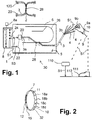
- a laying system 30 for producing an in Fig. 1 The indicated cable harness 2 has a laying table 1, a control and evaluation device 8 which represents part of the laying table 1 or is arranged externally to the laying table 1, and a mobile unit 10.
- the wire harness 2, e.g. B. a cable harness is composed of several individual cables 3, each cable 3 having one or more electrical lines 4, optionally together with optical lines.
- the laying table 1 has a laying surface 5, in or on which a display device 6 is provided.
- the laying surface 5 can be formed by the display device 6 itself.
- the mobile unit 10 and the control and evaluation device 8 together form a detection device, which together with the laying table 1 thus forms the laying system 30.
- a user 9 slips on a portable mobile unit 10 according to an embodiment of the invention, which is designed here with a bracelet 7 (arm strap) as a fastening device and z. B. is placed over the user's wrist 9a so that it is in contact with the user's skin.
- the user takes a cable 3 with a connector 20 provided on a first end 3a of the cable 3 and inserts the connector 20 into a connector holder 22 (plug-in module) which is provided on the installation table 5 and is connected to the control and evaluation device 8, and takes a line 4 of the cable 3rd
- Fig. 1 also a stationary unit 110 with transmission of the detection frequency signals S1 to the user 9, and / or z. B. a conductive underground 1 12, z. B. floor can be provided, via which the detection frequency signals S1 to the user, for. B. clothing such. B. a shoe 111 of the user 9 are transmitted.
- the user 9 picks up the detection frequency signals S1 from a conductive environment and forwards them, or they are transmitted wirelessly to a converter on the body of the user for conversion into the capacitive signals.
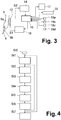
- the mobile unit 10 also has a display device 32, e.g. with multiple signal lights to indicate a status or multiple status information such as B. "Not ready for use, ready for use, in (transmission) operation, battery weak".
- the functionality of the control units 18a, 18b, 18c, 18d can advantageously be freely programmable.
- the capacitive coupler 12 outputs capacitive detection frequency signals S1 via the body of the user 9. If the user 9 according to Fig. 1 touches a line 4 of the cable 3 with his fingers 9b - one touch is sufficient here. B. the electrical insulation / stranded wire on line 4 - again enables capacitive data transmission from fingers 9b to line 4, so that signals S1 can be transmitted via line 4 through cable 3.
- the plug holder 22 (plug-in module) is connected to a communication interface 24 of the control and evaluation device 8, which thus receives and demodulates the detection frequency signals S1, and is also designed accordingly for outputting two capacitive frequency signals S2, which are returned via the Connector bracket 22, the connector 20, the line 4 and the user 9 are transmitted to the mobile unit 10.
- the control and evaluation device 8 is still - z. B. via a data interface - connected to the display device 6 to display signals Output S3, which are used by the display device 6 for the two-dimensional optical display of a laying path 26.
- control and evaluation device 8 Since the user 9 touches a line 4 of the cable 3 with the fingers 9b of the hand on which the mobile unit 10 is held as a bracelet, data communication is started, in which the mobile unit 10 sends first frequency signals S1 to the control and outputs evaluation device 8.
- the control and evaluation device 8 thus recognizes the cable 3 and accesses an internal - or external - memory 8a with current data about the cable harness 2 to be formed. From this, the control and evaluation device 8 forms display signals S3, which it outputs to the display device 6.
- the display device 6 is here, for. B. as a two-dimensional display unit, d. H. Display matrix, e.g. Example, as an LED or LCD panel, which directly indicates the installation path provided for the present cable 3.
- the user thus recognizes the current laying path 26 and can lay the cable 3 currently selected by him according to the laying path 26 on the laying table 1, the cable 3 advantageously in each case provided in receptacles 28, such as. B. clamps, etc., is firmly received, so that a cable harness 2 or wiring harness is formed with firmly connected individual cables 3, which are laid in predetermined installation paths 26.
- the user can the second end 3b of the cable 3 with the still open or individual lines 4 z. B. provided with a second connector 120, and in turn plug the second connector 120 into a suitable connector holder, which is indicated to him by the installation path 26.
- the user 9 selects the next cable 3, plugs its plug 20 into the plug holder 22 suitable for this purpose and touches a line 4 with his fingers 9b, so that the suitable routing path 26 is shown again by the control and evaluation device 8 becomes.
- the wire harness 2 or wire harness is successively formed from the individual cables 3.
- the user ID stored in the memory 17 of the mobile unit 10 enables the mobile unit to be uniquely assigned to the user.
- multi-user operation or multi-person operation is possible, in which a plurality of users 9 thus form the cable harness 2, the mobile units 10 advantageously output different detection frequency signals S1, the differentiation using different frequencies, e.g. B. in the frequency band from 2 to 10 MHz, so the frequency signals S1 do not interfere.
- additional information about the cable 3 can be displayed to the user via the display device 6, e.g. B. the number of lines 4.
- a cable harness 2 takes place through natural movements, in which a user grips lines 4 of a cable 3 with the fingers 9b of the relevant hand, provided on the mobile unit 10, and immediately visually takes the laying path 26, possibly also further ones Information that is displayed.
- Fig. 5 shows an embodiment of the signal demodulation and signal processing by the control and evaluation device 8: a plurality of plug holders 22, which are referred to here as 22a, 22b, 22c, 22d, each receive a cable 3 with plug 22, which, as described above, receive detection frequency signals S1 of the mobile unit.
- the connector brackets 22a to 22d are connected to the communication interface 24, which is designed here as a demodulator and multiplexer and z.
- B. scanned the connector holders 22, the detection frequency signals S1 demodulated and multiplexed to the control and evaluation device 8, which then uses data from the internal or external storage device 8a as described and outputs the display signals S3.
- the plug holders 22 and the display device 6 are part of the laying table 1; the control and evaluation device 8 together with the communication interface 24 can be designed externally or as part of the installation table 1.
Landscapes
- Engineering & Computer Science (AREA)
- Manufacturing & Machinery (AREA)
- Computer Networks & Wireless Communication (AREA)
- Signal Processing (AREA)
- Testing Of Short-Circuits, Discontinuities, Leakage, Or Incorrect Line Connections (AREA)
- Electric Cable Installation (AREA)
- Telephone Function (AREA)
- Looms (AREA)
- Length Measuring Devices With Unspecified Measuring Means (AREA)
Description
Die Erfindung betrifft eine Detektionseinrichtung für ein Kabelstrang-Verlegesystem, ein derartiges Verlegesystem sowie ein Verfahren zum Herstellen eines Kabelstrangs.The invention relates to a detection device for a cable harness laying system, such a laying system and a method for producing a cable harness.
Kabelstränge, z. B. Kabelbäume, werden insbesondere in Fahrzeuge, z. B. Kraftfahrzeugen, eingesetzt und weisen eine Vielzahl verschiedener Kabel mit angeschlossenen Steckern auf. Um einen Einbau der Kabelstränge zu ermöglichen, bei dem die Stecker an geeigneten Positionen für die Stecker-Halterungen angeordnet sind und die Kabel geordnet und übersichtlich geführt sind, sind die Kabel im Allgemeinen entlang geeigneter Verlegepfaden verlegt und fixiert, z. B. über Kabelschellen und Kabelhalter.Cable harnesses, e.g. B. harnesses are used in particular in vehicles such. B. motor vehicles, used and have a variety of different cables with connected plugs. In order to enable installation of the cable harnesses, in which the plugs are arranged at suitable positions for the plug holders and the cables are arranged in an orderly and clear manner, the cables are generally laid and fixed along suitable laying paths, e.g. B. via cable clamps and cable holder.
Hierzu sind Kabelstrang-Verlegetische bzw. Verlegetische bekannt, an denen die Kabelstränge von einem Benutzer sukzessive ausgebildet werden. Hierzu werden z. B. teilweise vorkonfektionierte Kabel verwendet, an denen z. B. jeweils an einem ersten Ende ein Stecker angebracht ist. Ein derartiges Kabel kann im Allgemeinen ein oder mehrere elektrische Leitungen, d. h. mit Litze oder Kunststoffhüllen versehene Drähte, aufweisen, je nach Anzahl der Pole der Stecker. Der Benutzer ergreift ein derartiges Kabel, wobei er den bereits vorkonfektionierten Stecker in eine Stecker-Halterung stecken kann, das Kabel oder auch einzelne Leitungen des Kabels in geeigneter Weise entlang eines Verlegepfades verlegt und fixiert und nachfolgend - bei nichtvorkonfektionierten Leitungen - gegebenenfalls das Kabel geeignet kürzt und hierbei das zweite Ende ausbildet und den zweiten Stecker an das zweite Ende crimpt bzw. montiert. Eine ordnungsgemäße und sichere Verlegung ist für eine nachfolgende sichere Funktionalität des Kabelbaums wichtig, wobei zum Teil eine sehr hohe Anzahl verschiedener Kabel entlang definierter Wege bzw. Verlegungs-Pfade zu verlegen sind, um eine sichere und kompakte Ausbildung zum Verlegen z. B. in einem Fahrzeug zu ermöglichen.For this purpose, cable harness laying tables or laying tables are known, on which the cable harnesses are successively formed by a user. For this purpose, e.g. B. partially pre-assembled cables, on which, for. B. a connector is attached to a first end. Such a cable can generally have one or more electrical lines, ie wires provided with a strand or plastic sheath, depending on the number of poles of the plug. The user grips such a cable, whereby he can insert the pre-assembled plug into a connector holder, lay and fix the cable or even individual lines of the cable in a suitable manner along a laying path and subsequently - in the case of non-pre-assembled lines - possibly shorten the cable appropriately and here forms the second end and the second connector to the second Crimped or assembled at the end. Proper and safe routing is important for the subsequent safe functionality of the cable harness. B. in a vehicle.
Es ist grundsätzlich bekannt, Verlegepfade auf Anzeigeeinrichtungen anzuzeigen. Die Identität der Leitung wird z. B. durch Eingabe einer Nummer, oder auch Einlesen eines auf den Leitungen aufgebrachten Bar-Codes ermittelt, woraufhin dem Benutzer ggf. von einer Steuereinrichtung des Verlegetisches über eine Anzeigeeinrichtung ein Verlegepfad mitgeteilt wird.It is generally known to display installation paths on display devices. The identity of the line is z. B. determined by entering a number, or also reading a bar code applied to the lines, whereupon the user may be informed of a laying path by a control device of the laying table via a display device.
Die Verwendung einer geeigneten Anzeigeeinrichtung kann bereits die Dauer und den Aufwand der Verlegung verringern; dennoch ist die Verlegung von Kabeln zur Herstellung eines Kabelstrangs im Allgemeinen aufwändig. Die
Der Erfindung liegt die Aufgabe zugrunde, eine Detektionseinrichtung für ein Kabelstrang- Verlegesystem, ein Verlegesystem sowie ein Verfahren zum Herstellen eines Kabelstrangs zu schaffen, die eine sichere und effektive Ausbildung der Kabelstränge ermöglichen.The invention has for its object a detection device for a cable harness laying system, a laying system and a method to create a harness that allow safe and effective formation of the harness.
Diese Aufgabe wird durch eine Detektionseinrichtung für ein Kabelstrang- Verlegesystem, ein Verlegesystem mit der Detektionseinrichtung sowie das Verfahren nach den unabhängigen Ansprüchen gelöst. Die Unteransprüche beschreiben bevorzugte Weiterbildungen.This object is achieved by a detection device for a cable harness laying system, a laying system with the detection device and the method according to the independent claims. The sub-claims describe preferred further developments.
Das erfindungsgemäße Verfahren ist insbesondere zur Verwendung der erfindungsgemäßen Detektionseinrichtung und des erfindungsgemäßen Verlegesystems vorgesehen; das Kabelstrang-Verlegesystem ist insbesondere zur Durchführung eines erfindungsgemäßen Verfahrens vorgesehen.The method according to the invention is intended in particular for using the detection device according to the invention and the laying system according to the invention; the cable harness laying system is provided in particular for carrying out a method according to the invention.
Das erfindungsgemäße Verlegesystem weist insbesondere die erfindungsgemäße Detektionseinrichtung sowie den Verlegetisch mitsamt Anzeigeeinrichtung und Steckeraufnahmen auf.The laying system according to the invention has in particular the detection device according to the invention and the laying table together with the display device and plug receptacles.
Hierbei kann der Verlegetisch auch als Prüftisch für eine nachfolgende Prüfung des Kabelstranges dienen.The laying table can also serve as a test table for a subsequent test of the cable harness.
Somit ist eine Einheit vorgesehen, die eine kapazitive Einkopplung von Signalen über den Körper bzw. die Haut des Benutzers ermöglicht. Hierzu weist die Einheit einen kapazitiven Koppler, insbesondere ein Coupling Pad, auf, das Erkennungs-Frequenzsignale einer geeigneten Frequenz kapazitiv in die Haut des Benutzers einkoppelt. Wenn somit der Benutzer mit seiner Hand, d.h. seinen Fingern, eine Leitung eines Kabels ergreift, können die elektrischen kapazitiven Erkennungs-Frequenzsignale ohne eine gesundheitliche Gefährdung des Benutzers über die Haut und die Hand des Benutzers in die Leitung kapazitiv eingekoppelt werden, wobei kein galvanischer Kontakt zwischen dem metallischen Draht der Leitung und der Hand erforderlich ist. Der Benutzer kann somit mit seinen Fingern z. B. die Kunststoff-Litze bzw. Kunststoffhülle einer Leitung ergreifen, wodurch bereits eine hinreichende kapazitive Kopplung sichergestellt ist.A unit is thus provided which enables a capacitive coupling of signals over the body or the skin of the user. For this purpose, the unit has a capacitive coupler, in particular a coupling pad, which capacitively couples detection frequency signals of a suitable frequency into the skin of the user. Thus, if the user grips a line of a cable with his hand, ie his fingers, the electrical capacitive detection frequency signals can be capacitively coupled into the line via the skin and the hand of the user without any health risk to the user, with no galvanic contact between the metallic wire of the line and the hand is required. The user can thus z. B. the plastic strand or take the plastic sleeve of a line, which already ensures a sufficient capacitive coupling.
Die Einheit kann insbesondere als mobile Einheit ausgebildet sein von einem Benutzer getragen werden, z. B. als Funktions-Armband.The unit can in particular be designed as a mobile unit to be carried by a user, e.g. B. as a functional bracelet.
Es sind jedoch weiterhin auch Ausbildungen möglich, bei denen die Einheit nicht am Körper des Benutzers angebracht wird, sondern die Erkennungs-Frequenzsignale vom Umfeld auf den Körper des Benutzers übertragen werden, insbesondere von einem leitfähigen Umfeld. So kann z. B. eine stationäre Einheit vorgesehen sein, von der die Erkennungs-Frequenzsignale auf den Körper des Benutzers übertragen werden, z. B. mit einem leitfähigen Untergrund, z. B. Fußboden, auf ein Kleidungsstück wie z. B. einen leitenden Schuh. Auch kann die stationäre Einheit an anderen Positionen im Umfeld vorgesehen sein und die Erkennungs-Frequenzsignale elektrisch auf den Benutzer übertragen, d.h. als Signalleitung zu dem Benutzer verlaufen. Weiterhin kann am Benutzer auch lediglich ein Umsetzer bzw. Wandler als mobile Einheit vorgesehen sein, wobei der Umsetzer z. B. drahtlose Signale einer stationären Einheit aufnimmt in die kapazitiven Signale umsetzt, so dass die Einheit durch die mobile Einheit (Umsetzer, Wandler) und die stationäre Einheit gebildet ist, d.h. teilweise mobil ist. Relevant ist, dass die Erkennungs-Frequenzsignale entnommen werden und direkt oder indirekt von dem Benutzer auf die Leitung des Kabels übertragen werden.However, further designs are also possible in which the unit is not attached to the body of the user, but rather the detection frequency signals are transmitted from the environment to the body of the user, in particular from a conductive environment. So z. B. a stationary unit can be provided from which the detection frequency signals are transmitted to the body of the user, for. B. with a conductive surface, e.g. B. floor, on a piece of clothing such. B. a conductive shoe. The stationary unit can also be provided at other positions in the environment and the detection frequency signals can be electrically transmitted to the user, i.e. run as a signal line to the user. Furthermore, only one converter or converter can be provided as a mobile unit on the user. B. records wireless signals from a stationary unit into the capacitive signals, so that the unit is formed by the mobile unit (converter, converter) and the stationary unit, i.e. is partially mobile. It is relevant that the detection frequency signals are extracted and transmitted directly or indirectly by the user to the cable.
Der Erfindung liegt hierbei der Gedanke zugrunde, eine natürliche Benutzerführung zu ermöglichen, die die manuelle Handhabung eines Kabels durch den Benutzer, zur Verlegung auf einem Verlegetisch, möglichst einbezieht und keine oder wenige ergänzenden Schritte bzw. Bearbeitungsvorgänge durch den Benutzer erfordert. Hierbei wird erfindungsgemäß erkannt, dass bereits das Ergreifen einer Leitung eines Kabels durch den Benutzer eine elektrische Datenverbindung ermöglicht, und durch die Einheit somit eine Datenkommunikation ermöglicht wird, wenn das Kabel bereits an dem Verlegetisch angeschlossen ist.The invention is based on the idea of enabling natural user guidance, which as far as possible includes manual handling of a cable by the user for laying on a laying table and requires no or few additional steps or processing operations by the user. Here, it is recognized according to the invention that the grasping of a line of a cable by the user enables an electrical data connection, and thus by the unit data communication is enabled when the cable is already connected to the lay table.
Somit kann durch Einstecken des Kabels mit dem Stecker in die KabelHalterung und anschließendes Ergreifen einer Leitung durch den Benutzer bereits eine Datenkommunikation gestartet werden, aufgrund der eine Steuer- und Auswerteeinrichtung des Verlegetisches erkennt, welches Kabel in die hierfür geeignete Stecker-Halterung gesteckt wurde, und daraufhin Anzeigesignale ausgibt, die auf der Anzeigeeinrichtung des Verlegetisches als Verlegepfad angezeigt werden, z. B. auf einem zweidimensionalen Display, das die Aufnahmefläche des Verlegetisches bildet.Thus, by inserting the cable with the plug into the cable holder and then grasping a line by the user, data communication can already be started, on the basis of which a control and evaluation device of the laying table recognizes which cable has been inserted into the suitable plug holder, and thereupon outputs display signals which are displayed on the display device of the laying table as a laying path, e.g. B. on a two-dimensional display that forms the receiving surface of the installation table.
Nach Verlegen des Kabels, im Allgemeinen unter Fixierung des Kabels in geeigneten Kabelaufnahmen, Schellen usw. und Anbringung des zweiten Steckers, kann somit nachfolgend von dem Benutzer das nächste Kabel genommen, in die geeignete Stecker-Halterung gesteckt und eine Leitung mit seiner Hand ergriffen werden, so dass die Steuer- und Auswerteeinrichtung wiederum nun selbsttätig erkennt, dass nunmehr das nachfolgende, vom Benutzer gewählte Kabel zu verlegen ist.After laying the cable, generally by fixing the cable in suitable cable holders, clamps etc. and attaching the second connector, the user can subsequently take the next cable, plug it into the appropriate connector holder and take a line with his hand , so that the control and evaluation device again automatically recognizes that the subsequent cable selected by the user is now to be laid.
Somit wird ein Herstellungsverfahren für Kabelstränge geschaffen, bei dem sukzessive nach der einseitigen Kontaktierung des Kabels über den Stecker mit dem Verlegetisch
- nachfolgend der Benutzer mit seiner Hand eine Leitung des Kabels ergreift,
- woraufhin das Kabel von der Auswerte- und Steuereinrichtung des Verlegesystems erkannt und der vorgesehene Verlegepfad auf einer Anzeigeeinrichtung angezeigt wird,
- woraufhin der Benutzer das Kabel und/oder die Leitungen des Kabels entlang des angezeigten Verlegepfades verlegt und fixiert, das zweite Ende eventuell geeignet kürzt (crimpt) und den zweiten Stecker montiert,
- nachfolgend gegebenenfalls weitere Leitungen desselben Kabels entlang des zugehörigen Verlegepfades verlegt werden,
- nach der Verlegung des Kabels bzw. seiner Leitungen das Verfahren durch Auswahl des nächsten Kabels zurückgesetzt wird.
- subsequently the user takes a line of the cable with his hand,
- whereupon the cable is recognized by the evaluation and control device of the laying system and the intended laying path is displayed on a display device,
- whereupon the user routes and fixes the cable and / or the lines of the cable along the indicated laying path, the second end may be suitably shortened (crimped) and the second connector installed,
- subsequently, if necessary, further lines of the same cable are laid along the associated laying path,
- after laying the cable or its lines, the procedure is reset by selecting the next cable.
Somit sind Fehlfunktionen bzw. Fehl-Verlegungen, bei denen für Kabel falsche Verlegepfade verwendet werden, d. h. Verwechslungen der Kabel durch den Benutzer usw., im Allgemeinen ausgeschlossen.Malfunctions or misalignments in which the wrong installation paths are used for cables are thus H. Confusion of the cables by the user etc., generally excluded.
Es wird eine benutzerfreundliche Führung ermöglicht, die den natürlichen Bewegungsablauf des Benutzers beim Verlegen eines Kabels nicht unterbricht; der Benutzer steckt ein Kabel ein, ergreift eine Leitung und kann direkt den individuellen Verlegepfad sehen und das Kabel verlegen, und nachfolgend das nächste Kabel ergreifen.A user-friendly guidance is made possible, which does not interrupt the natural movement of the user when laying a cable; the user plugs in a cable, grabs a line and can directly see the individual installation path and route the cable, and then take the next cable.
Derartige Signal-Übertragungen über den menschlichen Körper durch Einkopplung von kapazitiven Frequenzsignalen sind als solche bekannt, insbesondere als Human Body Communication (HBC), und für die menschliche Gesundheit ungefährlich. Sie können z. B. im Frequenzbereich von einigen MHz erfolgen und weisen im Allgemeinen derartig geringe Stromstärken auf, dass keine Gefährdung vorliegt und auch der Benutzer keine Empfindung wahrnimmt. Grundsätzlich ist auch möglich, dass der Benutzer hierbei einen elektrisch leitenden Handschuh trägt.Such signal transmissions via the human body by coupling capacitive frequency signals are known as such, in particular as Human Body Communication (HBC), and are harmless to human health. You can e.g. B. in the frequency range of a few MHz and generally have such low currents that there is no hazard and the user perceives no sensation. In principle, it is also possible for the user to wear an electrically conductive glove.
Bei Einsatz einer mobilen Einheit wird diese am Körper des Benutzers angebracht; sie kann insbesondere ein Funktions-Armband sein. Somit kann der Benutzer die Leitung jeweils mit derjenigen Hand, an der seine mobile Einheit bzw. das Funktions-Armband angebracht ist, ergreifen, da somit ein kurzer Signalweg über seinen Körper vorliegt, nämlich z. B. lediglich über einen Teilbereich seiner Hand zu den Fingern.When using a mobile unit, this is attached to the user's body; in particular, it can be a functional bracelet. Thus, the user can take the line with the hand on which his mobile unit or the functional wristband is attached, since there is thus a short signal path over his body, namely e.g. B. only over a portion of his hand to the fingers.
Ein derartiges Funktions-Armband weist im Allgemeinen einen Energiespeicher, z. B. eine Batterie oder Akkumulator auf, das für eine längere Zeitdauer, insbesondere eine Schicht eines Montageprozesses, ausreichend ist, so dass keine Unterbrechungen erforderlich sind. Die mobile Einheit ist somit leicht und stört bei der Handhabung nicht.Such a functional bracelet generally has an energy storage, for. B. a battery or accumulator that is sufficient for a longer period of time, in particular one layer of an assembly process, so that no interruptions are required. The mobile unit is therefore light and does not interfere with handling.
Weiterhin sind vorzugsweise Betätigungseinrichtungen wie z. B. Schalter oder Tasten, die vorzugsweise programmierbar sind zur Einstellung von-Funktionen. Weiterhin kann eine Anzeigeeinrichtung vorgesehen sein, z.B. mit mehreren Signalleuchten zum Anzeigen eines Status bzw. mehrerer Statusangaben.Furthermore, actuators such. B. switches or buttons, which are preferably programmable for setting functions. A display device can also be provided, e.g. with multiple signal lights to indicate a status or multiple status information.
Gemäß einer besonders bevorzugten Ausbildung sind in der Einheit Benutzer-Daten bzw. eine Benutzer-ID gespeichert, die den Benutzer eindeutig identifiziert. Somit kann z. B. nachträglich ein Benutzer identifiziert werden, der einen Montageprozess vorgenommen hat. Insbesondere sind auch Multi-User-Verfahren möglich, bei denen somit mehrere Benutzer mit unterschiedlichen Benutzer-IDs gemeinsam einen Kabelstrang verlegen, wobei die von ihren Einheiten jeweils ausgesandten Erkennungs-Frequenzsignale eine eindeutige Zuordnung bzw. Identifizierung ermöglichen.According to a particularly preferred embodiment, user data or a user ID that uniquely identifies the user are stored in the unit. Thus, e.g. B. subsequently identified a user who has carried out an assembly process. In particular, multi-user methods are also possible, in which several users with different user IDs thus jointly lay a cable harness, the detection frequency signals respectively sent out by their units allowing unambiguous assignment or identification.
Hierbei kann die Identifizierung z. B. über unterschiedliche Frequenzen, oder auch in den übertragenen Daten der Frequenzsignale, erfolgen.Here, the identification z. B. over different frequencies, or in the transmitted data of the frequency signals.
In z. B. einer internen oder externen Speichereinrichtung der Steuer- und Auswerteeinrichtung des Verlegetisches sind vorzugsweise die Verlegepfade für die einzelnen Kabel und z. B. Daten über die Benutzer-IDs gespeichert. Wenn somit die Steuer- und Auswerteeinrichtung über eine Stecker-Halterung des Verlegetisches Erkennungs-Frequenzsignale aufnimmt, kann sie sofort den Prozess starten, bei der sie das Kabel aufgrund der angesprochenen Stecker-Halterung identifiziert, die zugehörigen Anzeigesignale für das betreffende Kabel aus der Speichereinrichtung entnimmt und zur Anzeige des Verlegepfades an die Anzeigeeinrichtung ausgibt. Somit wird ein sicheres und benutzerfreundliches Verfahren zur individuellen Herstellung eines Kabelstranges ermöglicht.In e.g. B. an internal or external storage device of the control and evaluation device of the laying table are preferably the laying paths for the individual cables and z. B. Data about user IDs stored. If the control and evaluation device thus receives detection frequency signals via a plug holder of the laying table, it can immediately start the process in which it addresses the cable based on the address The connector holder is identified, the associated display signals for the cable in question are removed from the storage device and output to the display device to display the installation path. This enables a safe and user-friendly process for the individual production of a cable harness.
Die Erfindung wird im Folgenden anhand der beiliegenden Zeichnungen an einigen Ausführungsformen näher erläutert. Es zeigen:
- Fig. 1
- einen Verlegetisch mit einer Detektionseinrichtung gemäß einer Ausführungsform der Erfindung;
- Fig. 2
- die mobile Einheit aus
Fig. 1 in vergrößerter Darstellung; - Fig. 3
- ein Blockschaltbild der mobilen Einheit;
- Fig. 4
- ein Flussdiagramm eines erfindungsgemäßen Verfahrens.
- Fig. 1
- a laying table with a detection device according to an embodiment of the invention;
- Fig. 2
- the mobile unit
Fig. 1 in an enlarged view; - Fig. 3
- a block diagram of the mobile unit;
- Fig. 4
- a flowchart of a method according to the invention.
Ein Verlegesystem 30 zur Herstellung eines in
Der Verlegetisch 1 weist eine Verlegefläche 5 auf, in oder an der eine Anzeigeeinrichtung 6 vorgesehen ist. Hierbei kann die Verlegefläche 5 durch die Anzeigeeinrichtung 6 selbst ausgebildet werden. Die mobile Einheit 10 und die Steuer- und Auswerteeinrichtung 8 bilden zusammen eine Detektionseinrichtung, die zusammen mit dem Verlegetisch 1 somit das Verlegesystem 30 bildet.The laying table 1 has a laying
Zur Ausbildung eines Kabelstrangs 2 streift ein Benutzer 9 sich gemäß einer erfindungsgemäßen Ausbildung eine tragbare mobile Einheit 10 über, die hier mit einem Armband 7 (Armschlaufe) als Befestigungseinrichtung ausgebildet ist und z. B. über das Handgelenk 9a des Benutzers gelegt wird, so dass sie in Kontakt mit der Haut des Benutzers ist. Der Benutzer nimmt ein Kabel 3 mit einem an einem ersten Ende 3a des Kabels 3 vorgesehenen Stecker 20 und steckt den Stecker 20 in eine Stecker-Halterung 22 (Steckmodul), die am Verlegetisch 5 vorgesehen und mit der Steuer- und Auswerteeinrichtung 8 verbunden ist, und ergreift eine Leitung 4 des Kabels 3.To form a
Alternativ zu der mobilen Einheit 10 kann nach
Die in
einen Energiespeicher 11, z. B. Batterie oder Akkumulator, für einen längeren Zeitraum,- einen kapazitiven Koppler 12, insbesondere als Metallfläche (capacitive coupling pad), der kapazitiv Erkennungs-Frequenzsignale S1 in den
Körper des Benutzers 9 einkoppelt, wobei hier insbesondere eine bidirektionale Datenübertragung erfolgen kann, - weiterhin einen Signal-
Demodulator 14, eine periphere Steuereinheit 15, einen Signal-Modulator 16, einen Speicher 17 - intern oder extern zu der peripheren Steuereinheit 15 -, um eine Benutzer-ID zu speichern, sowie Bedieneinheiten
- an
energy storage 11, for. B. battery or accumulator, for a longer period of time, - a
capacitive coupler 12, in particular as a metal surface (capacitive coupling pad), which capacitively couples detection frequency signals S1 into the body of theuser 9, in which case bidirectional data transmission in particular can take place, - a
signal demodulator 14, aperipheral control unit 15, asignal modulator 16, a memory 17 - internal or external to the peripheral control unit 15 - in order to store a user ID, - and
control units
Vorzugsweise weist die mobile Einheit 10 weiterhin eine Anzeigeeinrichtung 32 auf, z.B. mit mehreren Signalleuchten zum Anzeigen eines Status bzw. mehrerer Statusangaben wie z. B. "nicht betriebsbereit, betriebsbereit, in (Sende-) Betrieb, Akku schwach".Preferably, the
Die Funktionalität der Bedieneinheiten 18a, 18b, 18c, 18d kann vorteilhafterweise frei programmierbar sein. Der kapazitive Koppler 12 gibt kapazitive Erkennungs-Frequenzsignale S1 über den Körper des Benutzers 9 ab. Wenn der Benutzer 9 gemäß
Die Stecker-Halterung 22 (Steckmodul) ist an eine Kommunikations-Schnittstelle 24 der Steuer- und Auswerteeinrichtung 8 angeschlossen, die somit die Erkennungs-Frequenzsignale S1 aufnimmt und demoduliert, und entsprechend auch zur Ausgabe zweiter kapazitiver Frequenzsignale S2 ausgebildet ist, die zurück über die Stecker-Halterung 22, den Stecker 20, die Leitung 4 und den Benutzer 9 zu der mobilen Einheit 10 übertragen werden.The plug holder 22 (plug-in module) is connected to a
Die Steuer- und Auswerteeinrichtung 8 ist weiterhin - z. B. über eine Datenschnittstelle - mit der Anzeigeeinrichtung 6 verbunden, um Anzeige-signale S3 auszugeben, die von der Anzeigeeinrichtung 6 zur zweidimensionalen optischen Anzeige eines Verlegepfades 26 verwendet werden.The control and
Indem der Benutzer 9 mit den Fingern 9b der Hand, an der die mobile Einheit 10 als Armband aufgenommen ist, eine Leitung 4 des Kabels 3 berührt, wird eine Daten-Kommunikation gestartet, bei der die mobile Einheit 10 erste Frequenzssignale S1 an die Steuer- und Auswerteeinrichtung 8 ausgibt. Die Steuer- und Auswerteeinrichtung 8 erkennt somit das Kabel 3, und greift auf einen internen - oder externen - Speicher 8a mit aktuellen Daten über den auszubildenden Kabelstrang 2 zurück. Hieraus bildet die Steuer- und Auswerteeinrichtung 8 Anzeigesignale S3, die sie an die Anzeigeeinrichtung 6 ausgibt.Since the
Die Anzeigeeinrichtung 6 ist hier z. B. als zweidimensionale Anzeigeeinheit, d. h. Anzeige-Matrix, z. B. als LED oder LCD-Panel, ausgebildet, die direkt den für das vorliegende Kabel 3 vorgesehenen Verlegepfad anzeigt. Der Benutzer erkennt somit den aktuellen Verlegepfad 26 und kann das aktuell von ihm gewählte Kabel 3 entsprechend dem Verlegepfad 26 auf dem Verlegetisch 1 verlegen, wobei das Kabel 3 vorteilhafterweise jeweils in vorgesehene Aufnahmen 28, wie z. B. Schellen usw., fest aufgenommen wird, so dass ein Kabelstrang 2 oder Kabelbaum mit fest miteinander verbundenen einzelnen Kabeln 3 ausgebildet wird, die in vorbestimmten Verlegepfaden 26 verlegt sind.The
Anschließend kann der Benutzer das zweite Ende 3b des Kabels 3 mit den noch offenen oder einzelnen Leitungen 4 z. B. mit einem zweiten Stecker 120 versehen, und den zweiten Stecker 120 wiederum in eine geeignete Stecker-Halterung stecken, die ihm durch den Verlegepfad 26 angezeigt wird.Then the user can the
Nachfolgend wählt der Benutzer 9 das nächste Kabel 3 aus, steckt dessen Stecker 20 in die hierfür geeignete Stecker-Halterung 22 und berührt mit seinen Fingern 9b eine Leitung 4, so dass nachfolgend wiederum von der Steuer- und Auswerteeinrichtung 8 der hierfür geeignete Verlegepfad 26 dargestellt wird.Subsequently, the
Somit wird der Kabelstrang 2 bzw. Kabelbaum aus den einzelnen Kabeln 3 sukzessive ausgebildet.Thus, the
Die in dem Speicher 17 der mobilen Einheit 10 gespeicherte Benutzer-ID ermöglicht eine eindeutige Zuordnung der mobilen Einheit zu dem Benutzer. Vorteilhafterweise ist ein Multi-User-Betrieb bzw. eine Mehr-Personen-Bedienung möglich, bei der somit mehrere Benutzer 9 den Kabelstrang 2 ausbilden, wobei die mobilen Einheiten 10 hierbei vorteilhafterweise unterschiedliche Erkennungs-Frequenzsignale S1 ausgeben, wobei die Differenzierung durch unterschiedliche Frequenzen, z. B. im Frequenzband von 2 bis 10 MHz, erfolgen kann, somit stören sich die Frequenzsignale S1 nicht.The user ID stored in the
Ergänzend können dem Benutzer über die Anzeigeeinrichtung 6 ergänzende Informationen zu dem Kabel 3 angezeigt werden, z. B. die Anzahl der vorgesehenen Leitungen 4.In addition, additional information about the
Somit erfolgt die sukzessive Ausbildung eines Kabelstrangs 2 durch natürliche Bewegungen, bei denen ein Benutzer mit den Fingern 9b der relevanten Hand, an der mobilen Einheit 10 vorgesehen ist, Leitungen 4 eines Kabels 3 ergreift, und sofort optisch den Verlegepfad 26, ggf. auch weitere Informationen, angezeigt bekommt.Thus, the successive formation of a
mehrere Stecker-Halterungen 22, die hier als 22a, 22b, 22c, 22d bezeichnet sind, nehmen jeweils ein Kabel 3 mit Stecker 22 auf, die wie oben beschrieben Erkennungs-Frequenzsignale S1 der mobilen Einheit aufnehmen. Die Stecker- Halterungen 22a bis 22d sind an die Kommunikations-Schnittstelle 24 angeschlossen, die hier als Demodulator und Multiplexer ausgebildet ist und z. B. die Stecker-Halterungen 22 abscannt,die Erkennungs-Frequenzsignale S1 demoduliert und gemultiplext an die Steuer- und Auswerteeinrichtung 8 weitergibt, die dann wie beschrieben auf Daten aus der internen oder externen Speichereinrichtung 8a zurückgreift und die Anzeigesignale S3 ausgibt. Die Stecker-Halterungen 22 und die Anzeigeeinrichtung 6 sind Teil des Verlegetisches 1; die Steuer- und Auswerteeinrichtung 8 mitsamt der Kommunikations-Schnittstelle 24 können extern oder als Teil des Verlegetisches 1 ausgebildet sein.
a plurality of
Das erfindungsgemäße Verfahren zum Herstellen eines Kabelstrangs 2 oder Kabelbaums sieht somit gemäß
- Nach dem Start in Schritt St0 des Einrichtens, gemäß dem Vorbereitungen getroffen sind und
ein Benutzer 9 somit seinemobile Einheit 10 umgibt unddas Verlegesystem 30 bereitgestellt wird, - nimmt der Benutzer 9 nachfolgend in Schritt St1 des Kabel-Einsteckens
ein erstes Kabel 3,steckt den Stecker 20 des erstenEndes 3a in die geeignete Stecker-Halterung 22am Verlegetisch 1, so dass eine Datenverbindung mit der Steuer-und Auswerteeinrichtung 8 hergestellt ist, - gemäß Schritt St2 des Kabel-Erfassens ergreift der Benutzer 9 dann mit seinem Körper, insbesondere seinen Fingern 9b,
eine Leitung 4 desKabels 3, z. B. an deren Kunststoff-Hülle bzw. Litze, so dass die kapazitive Kopplung seiner mobilen Einheit 10mit der Leitung 4 und eine Datenverbindung mit der Steuer-und Auswerteeinrichtung 8 hergestellt wird, nachfolgend wird in Schritt St3 (Start Datenkommunikation) durch die Datenverbindung ein Datenaustausch bzw. Signalaustausch zwischen der mobilen Einheit 10 und der Steuer-und Auswerteeinrichtung 8 gestartet, - in Schritt St4 des Identifizierens ermittelt die Steuer-
und Auswerteeinrichtung 8, welche Benutzer-ID in der mobilen Einheit 10 gespeichert ist, und welchesKabel 3von dem Benutzer 9 ergriffen wurde, - gemäß Schritt St5 der Anzeige des Verlegepfades gibt die Steuer-
und Auswerteeinrichtung 8 nachfolgend Anzeigesignale S3 andie Anzeigeeinrichtung 6 zur Anzeige des Verlegepfades 26 auf derAnzeigeeinrichtung 6, - in Schritt St6 des Einsetzens der Leitung am Ende erfolgt der Anschluss eines zweiten Steckers 120 am zweiten
Ende 3b des Kabels 3 und Einsetzen des zweitenSteckers 120, - wobei bei einer Verlegung der einzelnen Leitungen 4 in einer ersten, inneren Schleife erst alle Leitungen 4 des
Steckers 3 verlegt werden und somit das Verfahren vor den Schritt St2 zurückgesetzt wird, und - nach Fertigstellung des
Steckers 3 das Verfahren gemäß der äußeren Schleife wiederum vor den Schritt St1 zurückgesetzt wird, indem der Benutzer 9 ein neuesKabel 3 einsteckt und eine Leitung 4 ergreift,bis der Kabelstrang 2 in Schritt St7 fertiggestellt ist.
- After the start in step St0 of setting up, according to which preparations have been made and a
user 9 thus surrounds hismobile unit 10 and the layingsystem 30 is provided, - If the
user 9 subsequently takes afirst cable 3 in step St1 of plugging in the cable, plugs theplug 20 of thefirst end 3a into thesuitable plug holder 22 on the installation table 1, so that a data connection is established with the control andevaluation device 8, - According to step St2 of the cable detection, the
user 9 then grips with his body, in particular hisfingers 9b, aline 4 of thecable 3, e.g. B. on its plastic sheath or strand, so that the capacitive coupling of itsmobile unit 10 with theline 4 and a data connection with the control andevaluation device 8 is established, subsequently in step St3 (start data communication) through the data connection a data exchange or signal exchange between themobile unit 10 and the control andevaluation device 8 has started, - in step St4 of the identification, the control and
evaluation device 8 determines which user ID is stored in themobile unit 10 and whichcable 3 has been gripped by theuser 9, - According to step St5 of the display of the installation path, the control and
evaluation device 8 subsequently outputs display signals S3 to thedisplay device 6 for displaying theinstallation path 26 on thedisplay device 6, - in step St6 of inserting the line at the end, a
second plug 120 is connected to thesecond end 3b of thecable 3 and thesecond plug 120 is inserted, - wherein when the
individual lines 4 are laid in a first, inner loop, alllines 4 of theplug 3 are first laid, and thus the method is reset before step St2, and - after completion of the
connector 3, the process according to the outer loop is again reset before step St1 by theuser 9 inserting anew cable 3 and gripping aline 4 until thecable harness 2 is completed in step St7.
- 11
- VerlegetischLaying table
- 22nd
- Kabelstrang, z. B. KabelbaumHarness, e.g. B. Wiring harness
- 33rd
- Kabelelectric wire
- 3a3a
-
erstes Ende des Kabels 3first end of the
cable 3 - 3b3b
-
zweites Ende des Kabels 3second end of the
cable 3 - 44th
-
Leitung des Kabels 3
Cable 3 - 55
- VerlegeflächeLaying surface
- 66
- AnzeigeeinrichtungDisplay device
- 77
- Befestigungseinrichtung, z. B. Armband oder ArmringFastening device, e.g. B. bracelet or arm ring
- 88th
- Steuer- und AuswerteeinrichtungControl and evaluation device
- 8a8a
-
interne oder externe Speichereinrichtung der Steuer- und Auswerteeinrichtung 8internal or external storage device of the control and
evaluation device 8 - 99
- Benutzeruser
- 9a9a
- Handgelenkwrist
- 9b9b
- Fingerfinger
- 1010th
- mobile, tragbare Einheit, z. B. Funktions-Armbandmobile, portable unit, e.g. B. Functional bracelet
- 1111
- Energiespeicher, z. B. Batterie oder AkkuEnergy storage, e.g. B. battery or accumulator
- 1212th
-
kapazitiver Koppler der mobilen Einheit 10capacitive coupler of the
mobile unit 10 - 1414
-
Demodulator der mobilen Einheit 10Demodulator of the
mobile unit 10 - 1515
-
periphere Steuereinheit der mobilen Einheit 10peripheral control unit of the
mobile unit 10 - 1616
- Modulatormodulator
- 1717th
-
Speicher in der mobilen Einheit 10Memory in the
mobile unit 10 - 18a, b, c, d18a, b, c, d
- Bedieneinheiten, z. B. aktivierbare FunktionsflächenControl units, e.g. B. activatable functional areas
- 2020th
- Steckerplug
- 22, 22a - d22, 22a - d
- Stecker-HalterungConnector bracket
- 2424th
-
Kommunikations-Schnittstelle der Steuer- und Auswerteeinrichtung 8, z. B. als Demodulator und Multiplexer,Communication interface of the control and
evaluation device 8, for. B. as a demodulator and multiplexer, - 2626
-
Verlegepfad, angezeigt auf der Anzeigeeinrichtung 6Installation path, displayed on the
display device 6 - 3030th
- VerlegesystemLaying system
- 3232
-
Anzeigeeinrichtung an der mobilen Einheit 10Display device on the
mobile unit 10 - 110110
- stationäre Einheit zur Ausgabe der Erkennungs-Frequenzsignale (S1) an den Benutzer,stationary unit for outputting the detection frequency signals (S1) to the user,
- 111111
- Kleidung, z. B. Schuh, des Benutzers zur Aufnahme und Weiterleitung der Erkennungs-Frequenzsignale (S1),Clothing, e.g. B. Schuh, the user to record and forward the detection frequency signals (S1),
- 112112
- leitendes Umfeld, z. B. Untergrund (Fußboden) zur Weiterleitung der Erkennungs-Frequenzsignale (S1) an den Benutzer,leading environment, e.g. B. underground (floor) for forwarding the detection frequency signals (S1) to the user,
- 120120
- zweiter Steckersecond connector
- S1S1
-
Erkennungs-Frequenzsignal der Einheit 10, 110Detection frequency signal of the
unit - S2S2
-
Signale der Steuer- und Auswerteeinrichtung 8 zu der Einheit 10, 110Signals from the control and
evaluation device 8 to theunit - S3S3
-
Anzeigesignale von der Steuer- und Auswerteeinrichtung 8 an die Anzeigeeinrichtung 6,Display signals from the control and
evaluation device 8 to thedisplay device 6, - St0 bis St7St0 to St7
- Schritte des Verfahrens zur HerstellungSteps of the manufacturing process
Claims (15)
- Detection device (8; 10, 110) for a laying system (30) for producing a wiring loom (2), wherein the detection device has: a unit (10, 110) with a capacitive coupler (12) for coupling detection frequency signals (S1) into the body of the user (9), a control and evaluation device (8) for outputting display signals (S3) to a display device (6), wherein the control and evaluation device (8) is configured for data communication with the unit (10, 110) via plug holders (22) and the cable (3) connected to the plug holders, wherein the control and evaluation device (8) is designed to detect the connected cable (3) and/or single lines (4) of the cable (3), and wherein the control and evaluation device (8) is designed so that when a detection frequency signal (S1) of the unit (10, 110) is picked up via a plug holder (22) it outputs subsequent display signals (S3) to the display device (6) to display a laying path (26) for the connected cable (3) and/or single lines (4) of the cable (3).
- Detection device (8, 10) according to claim 1, characterised in that the unit is configured as a mobile unit (10) with a mounting device (7) for attachment to the user (9), preferably with an energy store (11), e.g. a battery or accumulator.
- Detection device according to claim 2, characterised in that the mobile unit (10) is configured as a functional strap for attachment to a hand, a wrist or an arm of a user (9).
- Detection device (8, 110) according to claim 1, characterised in that the unit is configured as a stationary unit (110) for transmission of the detection frequency signal (S1) to the user (9), in particular with a conductive environment, e.g. a conductive substrate (112) for transmission to the user (9).
- Detection device (8, 10) according to any one of the preceding claims, characterised in that the control and evaluation device (8) has a storage device (8a), in which data on the plugs (3), the associated laying paths (26) and the display signal (S3) and data on user IDs of the units (10, 110) and detection frequency signals (S1) of a plurality of units (10, 110) are stored.
- Detection device according to any one of the preceding claims, characterised in that the control and evaluation device (8) upon picking up a detection frequency signals (S1) automatically outputs the display signals (S3).
- Detection device according to any one of the preceding claims, characterised in that the control and evaluation device (8) is designed to scan the plurality of plug holders (22) and has a multiplexing device (24), in particular as part of a data interface (24) for multiplexing the detection frequency signals (S1) or demodulated detection frequency signals (S1).
- Detection device according to any one of the preceding claims, characterised in that the unit (10, 110) has:
a modulator (16) for generating the detection frequency signals (S1) and outputting to the capacitive coupler (12), and a peripheral control unit (15) for controlling the modulator (16). - Detection device (8; 10, 110) according to claim 8, characterised in that the unit (10, 110) also has:
a memory (17), e.g. an internal memory (17), for storing a user-ID, at least one preferably programmable operating device (18a, b, c, d), e.g. actuating surfaces, for operation by the user and activation of functions. - Detection device (8; 10, 110) according to claim 8 or 9, characterised in that the unit (10, 110) also has a display device (32) for displaying at least one operating status, e.g. an operating status to indicate an operation and/or an operating status to indicate an operational readiness, and/or to indicate a transmission status, and/or to indicate an energy store status.
- Detection device (8, 10, 110) according to any one of claims 8 to 10, characterised in that the unit (10, 110) also has a demodulator (14) for demodulation of picked-up second frequency signals (S2) of the control and evaluation device (8), for two-way data communication between the control and evaluation device (8) and the peripheral control unit (15) via the body of the user (9) and a line (4) of a cable (3).
- Laying system (30) for the production of wiring looms(2), having: a detection device according to any one of the preceding claims, a plurality of plug holders (22) each for receiving a plug (20) of a cable (3), a display device (6) for receiving the display signals (S3) and two-dimensional display of the laying paths (26), wherein the display device (6) has a two-dimensional display, forming a laying surface (5) for laying the cable (3) and/or the lines (4) of the cable (3) along the two-dimensional laying path (26), and wherein the plug holders (22) and the display device (6) are connected together via the control and evaluation device (8).
- Method of manufacture for a wiring loom (2), with at least the following steps:providing a laying table (1) with a display device (6) for the display of laying paths (26), a control and evaluation device (8), plug holders (22) connected to the control and evaluation device (8) and a unit for sending out detection frequency signals (S1) (StO),plugging a cable (3) by its plug (20) connected to its first end (3a) into a plug holder (22) of the laying table (1) (St1),establishing a communications link between the unit (10, 110) and the control and evaluation device (8) via a capacitive coupling via the user (9) and a line (4), gripped by the user, of the cable (3), the plug (20) and the plug holder (22), with outputting of detection frequency signals (S1) from the unit (10, 110) to the control and evaluation device (8) (St2), starting the data transmission between the unit (10, 110) and the control and evaluation device (8) (St3),detecting the connected cable (3) and/or single lines (4) of the cable (3) by the control and evaluation device (8), wherein stored data on the cables (3) are read out, (St4), outputting of display signals (S3) from the control and evaluation device (8) to the display device (6) and display of a laying path (26) for the cable (3) and/or single lines (4) of the cable (3) on the display device (6) (St5), completion of the cable (3) (St6), with the establishment of a new communications link between the unit (10, 110) and a further cable (3), repeating the steps from insertion of a cable (3), until the wiring loom (2) has been configured.
- Method according to claim 13, characterised in that when laying the single lines (4) of the cable (3) the steps from establishing a communications link (St2) onwards are repeated successively for the single lines (4) of the cable (3).
- Method according to claim 13 or 14, characterised in that with the picking up of a plurality of first frequency signals (S1) of a plurality of units (10, 110) and associated outputting of display signals (S3), a multi-user mode is feasible or executed.
Priority Applications (1)
| Application Number | Priority Date | Filing Date | Title |
|---|---|---|---|
| PL17749678T PL3494580T3 (en) | 2016-08-03 | 2017-07-28 | Detection device for a cable strand laying system |
Applications Claiming Priority (2)
| Application Number | Priority Date | Filing Date | Title |
|---|---|---|---|
| EP16182603.7A EP3279903A1 (en) | 2016-08-03 | 2016-08-03 | Detection device for a cable strand laying system |
| PCT/EP2017/069123 WO2018024621A1 (en) | 2016-08-03 | 2017-07-28 | Detection device for a wiring loom laying system |
Publications (2)
| Publication Number | Publication Date |
|---|---|
| EP3494580A1 EP3494580A1 (en) | 2019-06-12 |
| EP3494580B1 true EP3494580B1 (en) | 2020-04-29 |
Family
ID=56893676
Family Applications (2)
| Application Number | Title | Priority Date | Filing Date |
|---|---|---|---|
| EP16182603.7A Withdrawn EP3279903A1 (en) | 2016-08-03 | 2016-08-03 | Detection device for a cable strand laying system |
| EP17749678.3A Active EP3494580B1 (en) | 2016-08-03 | 2017-07-28 | Detection device for a cable strand laying system |
Family Applications Before (1)
| Application Number | Title | Priority Date | Filing Date |
|---|---|---|---|
| EP16182603.7A Withdrawn EP3279903A1 (en) | 2016-08-03 | 2016-08-03 | Detection device for a cable strand laying system |
Country Status (9)
| Country | Link |
|---|---|
| EP (2) | EP3279903A1 (en) |
| CN (1) | CN109690700B (en) |
| ES (1) | ES2808335T3 (en) |
| HU (1) | HUE050280T2 (en) |
| MA (1) | MA45847B1 (en) |
| MX (1) | MX2019001353A (en) |
| PL (1) | PL3494580T3 (en) |
| PT (1) | PT3494580T (en) |
| WO (1) | WO2018024621A1 (en) |
Families Citing this family (2)
| Publication number | Priority date | Publication date | Assignee | Title |
|---|---|---|---|---|
| WO2019242785A1 (en) * | 2018-06-18 | 2019-12-26 | Lisa Dräxlmaier GmbH | Assistance assembly method and assembly device |
| CN111914374A (en) * | 2019-06-24 | 2020-11-10 | 中车大同电力机车有限公司 | Pre-wiring system of screen cabinet |
Family Cites Families (8)
| Publication number | Priority date | Publication date | Assignee | Title |
|---|---|---|---|---|
| FR2808374A1 (en) * | 2000-04-27 | 2001-11-02 | Labinal | INSTALLATION FOR MANUFACTURING A WIRING HARNESS |
| US20030030206A1 (en) * | 2001-07-23 | 2003-02-13 | Yazaki Corporation | Wire harness arranging-purpose wire holding member and wire harness arranging-method |
| ES2443265B1 (en) * | 2012-08-16 | 2014-11-13 | Eads Construcciones Aeronauticas, S.A. | MANUFACTURING OR VERIFICATION BANK OF ELECTRIC MAZOS |
| JP2014192113A (en) * | 2013-03-28 | 2014-10-06 | Sumitomo Wiring Syst Ltd | Method for producing wire harness |
| FR3005375B1 (en) * | 2013-05-06 | 2017-01-13 | Laselec | SUPPORT FOR THE PRODUCTION OF CABLES HARNESS |
| JP2015076912A (en) * | 2013-10-07 | 2015-04-20 | パナソニックIpマネジメント株式会社 | Wiring capacity display system |
| US9818179B2 (en) * | 2013-12-05 | 2017-11-14 | Bombardier Transportation Gmbh | Method for manufacturing a wire harness |
| JP6213437B2 (en) * | 2014-09-25 | 2017-10-18 | 住友電装株式会社 | Wire harness manufacturing method and wire harness manufacturing apparatus |
-
2016
- 2016-08-03 EP EP16182603.7A patent/EP3279903A1/en not_active Withdrawn
-
2017
- 2017-07-28 EP EP17749678.3A patent/EP3494580B1/en active Active
- 2017-07-28 HU HUE17749678A patent/HUE050280T2/en unknown
- 2017-07-28 PT PT177496783T patent/PT3494580T/en unknown
- 2017-07-28 MA MA45847A patent/MA45847B1/en unknown
- 2017-07-28 WO PCT/EP2017/069123 patent/WO2018024621A1/en not_active Ceased
- 2017-07-28 ES ES17749678T patent/ES2808335T3/en active Active
- 2017-07-28 CN CN201780049335.4A patent/CN109690700B/en active Active
- 2017-07-28 MX MX2019001353A patent/MX2019001353A/en unknown
- 2017-07-28 PL PL17749678T patent/PL3494580T3/en unknown
Non-Patent Citations (1)
| Title |
|---|
| None * |
Also Published As
| Publication number | Publication date |
|---|---|
| WO2018024621A1 (en) | 2018-02-08 |
| MX2019001353A (en) | 2019-06-03 |
| CN109690700A (en) | 2019-04-26 |
| PT3494580T (en) | 2020-08-03 |
| CN109690700B (en) | 2020-07-24 |
| EP3279903A1 (en) | 2018-02-07 |
| PL3494580T3 (en) | 2020-11-16 |
| ES2808335T3 (en) | 2021-02-26 |
| HUE050280T2 (en) | 2020-12-28 |
| EP3494580A1 (en) | 2019-06-12 |
| MA45847B1 (en) | 2020-07-29 |
Similar Documents
| Publication | Publication Date | Title |
|---|---|---|
| EP1390790B1 (en) | Optical distribution device and light waveguide connector cable | |
| EP2842899B1 (en) | Measuring tape for an elevator | |
| DE102007046385A1 (en) | Optical fiber sensor with electrical connections | |
| EP2338207B1 (en) | Rfid transponder antenna | |
| DE102011005302A1 (en) | Wear detection system and method | |
| DE102006014021B4 (en) | A power line communication system | |
| DE2606067A1 (en) | DIGITAL SYSTEM FOR CONTROLLING ASYNCHRONOUS DATA TRANSFER | |
| WO2012019760A1 (en) | Ecg hand-held device | |
| DE102017223665A1 (en) | Electric battery module | |
| WO2008119477A2 (en) | Motor arrangement | |
| WO1998032249A2 (en) | Component-recognition and management system for optical networks | |
| WO2018024621A1 (en) | Detection device for a wiring loom laying system | |
| EP1171891B1 (en) | Cables for manually wiring the electrical devices of a complex, individual installation and method for producing the cable | |
| WO2017005495A1 (en) | System for identifying a seat location | |
| EP0596344A1 (en) | Connector device for ECG electrodes | |
| EP1233315B1 (en) | Method and device for configuring an electrical end apparatus | |
| DE102019127468A1 (en) | Surgical device with integrated RFID readout antenna | |
| DE102009048617A1 (en) | Diagnostic system for motor vehicle, has motor vehicle-sided interface with wireless local area network module for wireless data transmission between onboard components and off-board component | |
| DE112019004681T5 (en) | Wiring element | |
| DE102018220483A1 (en) | Charging system for an electrically drivable vehicle, method for operating a charging system | |
| EP4170684A1 (en) | Cable with haptically detectable twisting indicator and method for laying such a cable without twisting | |
| DE102017007121A1 (en) | Method for operating an automatic parking garage | |
| DE112022001194T5 (en) | Cabling component | |
| EP2456187B1 (en) | Method for setting up a house communication system comprising at least one door station and at least one residence station | |
| DE102010043029A1 (en) | Selection circuit for an electrode assembly and method for operating and for producing an electrode assembly |
Legal Events
| Date | Code | Title | Description |
|---|---|---|---|
| STAA | Information on the status of an ep patent application or granted ep patent |
Free format text: STATUS: UNKNOWN |
|
| STAA | Information on the status of an ep patent application or granted ep patent |
Free format text: STATUS: THE INTERNATIONAL PUBLICATION HAS BEEN MADE |
|
| PUAI | Public reference made under article 153(3) epc to a published international application that has entered the european phase |
Free format text: ORIGINAL CODE: 0009012 |
|
| STAA | Information on the status of an ep patent application or granted ep patent |
Free format text: STATUS: REQUEST FOR EXAMINATION WAS MADE |
|
| 17P | Request for examination filed |
Effective date: 20190115 |
|
| AK | Designated contracting states |
Kind code of ref document: A1 Designated state(s): AL AT BE BG CH CY CZ DE DK EE ES FI FR GB GR HR HU IE IS IT LI LT LU LV MC MK MT NL NO PL PT RO RS SE SI SK SM TR |
|
| AX | Request for extension of the european patent |
Extension state: BA ME |
|
| DAX | Request for extension of the european patent (deleted) | ||
| RAV | Requested validation state of the european patent: fee paid |
Extension state: MA Effective date: 20190115 |
|
| GRAP | Despatch of communication of intention to grant a patent |
Free format text: ORIGINAL CODE: EPIDOSNIGR1 |
|
| STAA | Information on the status of an ep patent application or granted ep patent |
Free format text: STATUS: GRANT OF PATENT IS INTENDED |
|
| INTG | Intention to grant announced |
Effective date: 20191205 |
|
| GRAS | Grant fee paid |
Free format text: ORIGINAL CODE: EPIDOSNIGR3 |
|
| GRAA | (expected) grant |
Free format text: ORIGINAL CODE: 0009210 |
|
| STAA | Information on the status of an ep patent application or granted ep patent |
Free format text: STATUS: THE PATENT HAS BEEN GRANTED |
|
| AK | Designated contracting states |
Kind code of ref document: B1 Designated state(s): AL AT BE BG CH CY CZ DE DK EE ES FI FR GB GR HR HU IE IS IT LI LT LU LV MC MK MT NL NO PL PT RO RS SE SI SK SM TR |
|
| REG | Reference to a national code |
Ref country code: GB Ref legal event code: FG4D Free format text: NOT ENGLISH |
|
| REG | Reference to a national code |
Ref country code: CH Ref legal event code: EP |
|
| REG | Reference to a national code |
Ref country code: AT Ref legal event code: REF Ref document number: 1264523 Country of ref document: AT Kind code of ref document: T Effective date: 20200515 |
|
| REG | Reference to a national code |
Ref country code: DE Ref legal event code: R096 Ref document number: 502017005060 Country of ref document: DE |
|
| REG | Reference to a national code |
Ref country code: IE Ref legal event code: FG4D Free format text: LANGUAGE OF EP DOCUMENT: GERMAN |
|
| REG | Reference to a national code |
Ref country code: MA Ref legal event code: VAGR Ref document number: 45847 Country of ref document: MA Kind code of ref document: B1 |
|
| REG | Reference to a national code |
Ref country code: PT Ref legal event code: SC4A Ref document number: 3494580 Country of ref document: PT Date of ref document: 20200803 Kind code of ref document: T Free format text: AVAILABILITY OF NATIONAL TRANSLATION Effective date: 20200728 |
|
| REG | Reference to a national code |
Ref country code: NL Ref legal event code: MP Effective date: 20200429 |
|
| REG | Reference to a national code |
Ref country code: LT Ref legal event code: MG4D |
|
| PG25 | Lapsed in a contracting state [announced via postgrant information from national office to epo] |
Ref country code: FI Free format text: LAPSE BECAUSE OF FAILURE TO SUBMIT A TRANSLATION OF THE DESCRIPTION OR TO PAY THE FEE WITHIN THE PRESCRIBED TIME-LIMIT Effective date: 20200429 Ref country code: SE Free format text: LAPSE BECAUSE OF FAILURE TO SUBMIT A TRANSLATION OF THE DESCRIPTION OR TO PAY THE FEE WITHIN THE PRESCRIBED TIME-LIMIT Effective date: 20200429 Ref country code: NO Free format text: LAPSE BECAUSE OF FAILURE TO SUBMIT A TRANSLATION OF THE DESCRIPTION OR TO PAY THE FEE WITHIN THE PRESCRIBED TIME-LIMIT Effective date: 20200729 Ref country code: IS Free format text: LAPSE BECAUSE OF FAILURE TO SUBMIT A TRANSLATION OF THE DESCRIPTION OR TO PAY THE FEE WITHIN THE PRESCRIBED TIME-LIMIT Effective date: 20200829 Ref country code: LT Free format text: LAPSE BECAUSE OF FAILURE TO SUBMIT A TRANSLATION OF THE DESCRIPTION OR TO PAY THE FEE WITHIN THE PRESCRIBED TIME-LIMIT Effective date: 20200429 Ref country code: GR Free format text: LAPSE BECAUSE OF FAILURE TO SUBMIT A TRANSLATION OF THE DESCRIPTION OR TO PAY THE FEE WITHIN THE PRESCRIBED TIME-LIMIT Effective date: 20200730 |
|
| PG25 | Lapsed in a contracting state [announced via postgrant information from national office to epo] |
Ref country code: BG Free format text: LAPSE BECAUSE OF FAILURE TO SUBMIT A TRANSLATION OF THE DESCRIPTION OR TO PAY THE FEE WITHIN THE PRESCRIBED TIME-LIMIT Effective date: 20200729 Ref country code: RS Free format text: LAPSE BECAUSE OF FAILURE TO SUBMIT A TRANSLATION OF THE DESCRIPTION OR TO PAY THE FEE WITHIN THE PRESCRIBED TIME-LIMIT Effective date: 20200429 Ref country code: HR Free format text: LAPSE BECAUSE OF FAILURE TO SUBMIT A TRANSLATION OF THE DESCRIPTION OR TO PAY THE FEE WITHIN THE PRESCRIBED TIME-LIMIT Effective date: 20200429 Ref country code: LV Free format text: LAPSE BECAUSE OF FAILURE TO SUBMIT A TRANSLATION OF THE DESCRIPTION OR TO PAY THE FEE WITHIN THE PRESCRIBED TIME-LIMIT Effective date: 20200429 |
|
| REG | Reference to a national code |
Ref country code: HU Ref legal event code: AG4A Ref document number: E050280 Country of ref document: HU |
|
| PG25 | Lapsed in a contracting state [announced via postgrant information from national office to epo] |
Ref country code: NL Free format text: LAPSE BECAUSE OF FAILURE TO SUBMIT A TRANSLATION OF THE DESCRIPTION OR TO PAY THE FEE WITHIN THE PRESCRIBED TIME-LIMIT Effective date: 20200429 Ref country code: AL Free format text: LAPSE BECAUSE OF FAILURE TO SUBMIT A TRANSLATION OF THE DESCRIPTION OR TO PAY THE FEE WITHIN THE PRESCRIBED TIME-LIMIT Effective date: 20200429 |
|
| PG25 | Lapsed in a contracting state [announced via postgrant information from national office to epo] |
Ref country code: DK Free format text: LAPSE BECAUSE OF FAILURE TO SUBMIT A TRANSLATION OF THE DESCRIPTION OR TO PAY THE FEE WITHIN THE PRESCRIBED TIME-LIMIT Effective date: 20200429 Ref country code: IT Free format text: LAPSE BECAUSE OF FAILURE TO SUBMIT A TRANSLATION OF THE DESCRIPTION OR TO PAY THE FEE WITHIN THE PRESCRIBED TIME-LIMIT Effective date: 20200429 Ref country code: SM Free format text: LAPSE BECAUSE OF FAILURE TO SUBMIT A TRANSLATION OF THE DESCRIPTION OR TO PAY THE FEE WITHIN THE PRESCRIBED TIME-LIMIT Effective date: 20200429 Ref country code: EE Free format text: LAPSE BECAUSE OF FAILURE TO SUBMIT A TRANSLATION OF THE DESCRIPTION OR TO PAY THE FEE WITHIN THE PRESCRIBED TIME-LIMIT Effective date: 20200429 |
|
| REG | Reference to a national code |
Ref country code: DE Ref legal event code: R097 Ref document number: 502017005060 Country of ref document: DE |
|
| PG25 | Lapsed in a contracting state [announced via postgrant information from national office to epo] |
Ref country code: MC Free format text: LAPSE BECAUSE OF FAILURE TO SUBMIT A TRANSLATION OF THE DESCRIPTION OR TO PAY THE FEE WITHIN THE PRESCRIBED TIME-LIMIT Effective date: 20200429 Ref country code: SK Free format text: LAPSE BECAUSE OF FAILURE TO SUBMIT A TRANSLATION OF THE DESCRIPTION OR TO PAY THE FEE WITHIN THE PRESCRIBED TIME-LIMIT Effective date: 20200429 |
|
| REG | Reference to a national code |
Ref country code: ES Ref legal event code: FG2A Ref document number: 2808335 Country of ref document: ES Kind code of ref document: T3 Effective date: 20210226 Ref country code: CH Ref legal event code: PL |
|
| PLBE | No opposition filed within time limit |
Free format text: ORIGINAL CODE: 0009261 |
|
| STAA | Information on the status of an ep patent application or granted ep patent |
Free format text: STATUS: NO OPPOSITION FILED WITHIN TIME LIMIT |
|
| 26N | No opposition filed |
Effective date: 20210201 |
|
| REG | Reference to a national code |
Ref country code: BE Ref legal event code: MM Effective date: 20200731 |
|
| PG25 | Lapsed in a contracting state [announced via postgrant information from national office to epo] |
Ref country code: FR Free format text: LAPSE BECAUSE OF NON-PAYMENT OF DUE FEES Effective date: 20200731 Ref country code: CH Free format text: LAPSE BECAUSE OF NON-PAYMENT OF DUE FEES Effective date: 20200731 Ref country code: LI Free format text: LAPSE BECAUSE OF NON-PAYMENT OF DUE FEES Effective date: 20200731 Ref country code: LU Free format text: LAPSE BECAUSE OF NON-PAYMENT OF DUE FEES Effective date: 20200728 |
|
| PG25 | Lapsed in a contracting state [announced via postgrant information from national office to epo] |
Ref country code: BE Free format text: LAPSE BECAUSE OF NON-PAYMENT OF DUE FEES Effective date: 20200731 Ref country code: SI Free format text: LAPSE BECAUSE OF FAILURE TO SUBMIT A TRANSLATION OF THE DESCRIPTION OR TO PAY THE FEE WITHIN THE PRESCRIBED TIME-LIMIT Effective date: 20200429 |
|
| VSFP | Annual fee paid to validation state [announced via postgrant information from national office to epo] |
Ref country code: MA Payment date: 20200827 Year of fee payment: 4 |
|
| PG25 | Lapsed in a contracting state [announced via postgrant information from national office to epo] |
Ref country code: IE Free format text: LAPSE BECAUSE OF NON-PAYMENT OF DUE FEES Effective date: 20200728 |
|
| GBPC | Gb: european patent ceased through non-payment of renewal fee |
Effective date: 20210728 |
|
| PG25 | Lapsed in a contracting state [announced via postgrant information from national office to epo] |
Ref country code: GB Free format text: LAPSE BECAUSE OF NON-PAYMENT OF DUE FEES Effective date: 20210728 |
|
| PG25 | Lapsed in a contracting state [announced via postgrant information from national office to epo] |
Ref country code: TR Free format text: LAPSE BECAUSE OF FAILURE TO SUBMIT A TRANSLATION OF THE DESCRIPTION OR TO PAY THE FEE WITHIN THE PRESCRIBED TIME-LIMIT Effective date: 20200429 Ref country code: MT Free format text: LAPSE BECAUSE OF FAILURE TO SUBMIT A TRANSLATION OF THE DESCRIPTION OR TO PAY THE FEE WITHIN THE PRESCRIBED TIME-LIMIT Effective date: 20200429 Ref country code: CY Free format text: LAPSE BECAUSE OF FAILURE TO SUBMIT A TRANSLATION OF THE DESCRIPTION OR TO PAY THE FEE WITHIN THE PRESCRIBED TIME-LIMIT Effective date: 20200429 |
|
| PG25 | Lapsed in a contracting state [announced via postgrant information from national office to epo] |
Ref country code: MK Free format text: LAPSE BECAUSE OF FAILURE TO SUBMIT A TRANSLATION OF THE DESCRIPTION OR TO PAY THE FEE WITHIN THE PRESCRIBED TIME-LIMIT Effective date: 20200429 |
|
| REG | Reference to a national code |
Ref country code: AT Ref legal event code: MM01 Ref document number: 1264523 Country of ref document: AT Kind code of ref document: T Effective date: 20220728 |
|
| PG25 | Lapsed in a contracting state [announced via postgrant information from national office to epo] |
Ref country code: AT Free format text: LAPSE BECAUSE OF NON-PAYMENT OF DUE FEES Effective date: 20220728 |
|
| PGFP | Annual fee paid to national office [announced via postgrant information from national office to epo] |
Ref country code: PT Payment date: 20250625 Year of fee payment: 9 |
|
| PGFP | Annual fee paid to national office [announced via postgrant information from national office to epo] |
Ref country code: HU Payment date: 20250728 Year of fee payment: 9 |
|
| PGFP | Annual fee paid to national office [announced via postgrant information from national office to epo] |
Ref country code: ES Payment date: 20250819 Year of fee payment: 9 |
|
| PGFP | Annual fee paid to national office [announced via postgrant information from national office to epo] |
Ref country code: DE Payment date: 20250911 Year of fee payment: 9 |
|
| PGFP | Annual fee paid to national office [announced via postgrant information from national office to epo] |
Ref country code: PL Payment date: 20250717 Year of fee payment: 9 |
|
| PGFP | Annual fee paid to national office [announced via postgrant information from national office to epo] |
Ref country code: CZ Payment date: 20250715 Year of fee payment: 9 |
|
| PGFP | Annual fee paid to national office [announced via postgrant information from national office to epo] |
Ref country code: RO Payment date: 20250724 Year of fee payment: 9 |
|
| VSFP | Annual fee paid to validation state [announced via postgrant information from national office to epo] |
Ref country code: MA Payment date: 20230726 Year of fee payment: 7 |
|
| VSFP | Annual fee paid to validation state [announced via postgrant information from national office to epo] |
Ref country code: MA Payment date: 20220725 Year of fee payment: 6 Ref country code: MA Payment date: 20210907 Year of fee payment: 5 |
|
| VSFP | Annual fee paid to validation state [announced via postgrant information from national office to epo] |
Ref country code: MA Payment date: 20240708 Year of fee payment: 8 |
|
| VSFP | Annual fee paid to validation state [announced via postgrant information from national office to epo] |
Ref country code: MA Payment date: 20200827 Year of fee payment: 4 Ref country code: MA Payment date: 20250731 Year of fee payment: 9 |