EP3491280B1 - Plumbing fitting - Google Patents
Plumbing fitting Download PDFInfo
- Publication number
- EP3491280B1 EP3491280B1 EP17836122.6A EP17836122A EP3491280B1 EP 3491280 B1 EP3491280 B1 EP 3491280B1 EP 17836122 A EP17836122 A EP 17836122A EP 3491280 B1 EP3491280 B1 EP 3491280B1
- Authority
- EP
- European Patent Office
- Prior art keywords
- annular
- receiving
- locking
- fitting
- teeth
- Prior art date
- Legal status (The legal status is an assumption and is not a legal conclusion. Google has not performed a legal analysis and makes no representation as to the accuracy of the status listed.)
- Active
Links
- 238000009428 plumbing Methods 0.000 title claims description 70
- 125000006850 spacer group Chemical group 0.000 claims description 14
- 210000002445 nipple Anatomy 0.000 claims description 13
- 238000003825 pressing Methods 0.000 claims description 6
- 238000000034 method Methods 0.000 description 19
- 230000008878 coupling Effects 0.000 description 9
- 238000010168 coupling process Methods 0.000 description 9
- 238000005859 coupling reaction Methods 0.000 description 9
- 239000003292 glue Substances 0.000 description 9
- 239000004033 plastic Substances 0.000 description 5
- 238000004519 manufacturing process Methods 0.000 description 4
- 239000000463 material Substances 0.000 description 4
- 239000002699 waste material Substances 0.000 description 4
- 238000009434 installation Methods 0.000 description 3
- 230000009972 noncorrosive effect Effects 0.000 description 3
- XLYOFNOQVPJJNP-UHFFFAOYSA-N water Substances O XLYOFNOQVPJJNP-UHFFFAOYSA-N 0.000 description 3
- 239000004677 Nylon Substances 0.000 description 2
- 229910000831 Steel Inorganic materials 0.000 description 2
- 238000004026 adhesive bonding Methods 0.000 description 2
- 238000004378 air conditioning Methods 0.000 description 2
- 238000006243 chemical reaction Methods 0.000 description 2
- 239000000470 constituent Substances 0.000 description 2
- 238000010438 heat treatment Methods 0.000 description 2
- 239000002184 metal Substances 0.000 description 2
- 229920001778 nylon Polymers 0.000 description 2
- 229910001220 stainless steel Inorganic materials 0.000 description 2
- 239000010935 stainless steel Substances 0.000 description 2
- 239000010959 steel Substances 0.000 description 2
- 238000009423 ventilation Methods 0.000 description 2
- 239000000853 adhesive Substances 0.000 description 1
- 230000001070 adhesive effect Effects 0.000 description 1
- 238000004891 communication Methods 0.000 description 1
- 238000005520 cutting process Methods 0.000 description 1
- 238000005516 engineering process Methods 0.000 description 1
- 239000012530 fluid Substances 0.000 description 1
- 230000004927 fusion Effects 0.000 description 1
- 238000005304 joining Methods 0.000 description 1
- 238000004806 packaging method and process Methods 0.000 description 1
- 238000007789 sealing Methods 0.000 description 1
- 239000007787 solid Substances 0.000 description 1
- 231100000331 toxic Toxicity 0.000 description 1
- 230000002588 toxic effect Effects 0.000 description 1
- 238000003466 welding Methods 0.000 description 1
Images


Classifications
-
- F—MECHANICAL ENGINEERING; LIGHTING; HEATING; WEAPONS; BLASTING
- F16—ENGINEERING ELEMENTS AND UNITS; GENERAL MEASURES FOR PRODUCING AND MAINTAINING EFFECTIVE FUNCTIONING OF MACHINES OR INSTALLATIONS; THERMAL INSULATION IN GENERAL
- F16L—PIPES; JOINTS OR FITTINGS FOR PIPES; SUPPORTS FOR PIPES, CABLES OR PROTECTIVE TUBING; MEANS FOR THERMAL INSULATION IN GENERAL
- F16L37/00—Couplings of the quick-acting type
- F16L37/08—Couplings of the quick-acting type in which the connection between abutting or axially overlapping ends is maintained by locking members
- F16L37/084—Couplings of the quick-acting type in which the connection between abutting or axially overlapping ends is maintained by locking members combined with automatic locking
- F16L37/091—Couplings of the quick-acting type in which the connection between abutting or axially overlapping ends is maintained by locking members combined with automatic locking by means of a ring provided with teeth or fingers
- F16L37/0915—Couplings of the quick-acting type in which the connection between abutting or axially overlapping ends is maintained by locking members combined with automatic locking by means of a ring provided with teeth or fingers with a separate member for releasing the coupling
-
- F—MECHANICAL ENGINEERING; LIGHTING; HEATING; WEAPONS; BLASTING
- F16—ENGINEERING ELEMENTS AND UNITS; GENERAL MEASURES FOR PRODUCING AND MAINTAINING EFFECTIVE FUNCTIONING OF MACHINES OR INSTALLATIONS; THERMAL INSULATION IN GENERAL
- F16L—PIPES; JOINTS OR FITTINGS FOR PIPES; SUPPORTS FOR PIPES, CABLES OR PROTECTIVE TUBING; MEANS FOR THERMAL INSULATION IN GENERAL
- F16L21/00—Joints with sleeve or socket
- F16L21/08—Joints with sleeve or socket with additional locking means
-
- F—MECHANICAL ENGINEERING; LIGHTING; HEATING; WEAPONS; BLASTING
- F16—ENGINEERING ELEMENTS AND UNITS; GENERAL MEASURES FOR PRODUCING AND MAINTAINING EFFECTIVE FUNCTIONING OF MACHINES OR INSTALLATIONS; THERMAL INSULATION IN GENERAL
- F16L—PIPES; JOINTS OR FITTINGS FOR PIPES; SUPPORTS FOR PIPES, CABLES OR PROTECTIVE TUBING; MEANS FOR THERMAL INSULATION IN GENERAL
- F16L27/00—Adjustable joints, Joints allowing movement
- F16L27/12—Adjustable joints, Joints allowing movement allowing substantial longitudinal adjustment or movement
Definitions
- the present disclosure relates to plumbing fittings for use in drain, waste and vent (DWV) systems, and more particularly to plumbing fittings for connecting pipes together without the use of glue or any other type of fusion that may exist on any type of piping.
- DWV drain, waste and vent
- a fitting that is glued or fused to any type of plastic pipe for use in a DWV system must be cut off from the pipe in the event that it is not correctly connected and furthermore if there is some water flowing through the pipe the glue or fusing, the DWV system will not work properly, leading to a potential risk of water leakage and odor.
- installation of the fittings presents a high level of difficulty for some users.
- Document US9068680 discloses a push fitting joint packaging arrangement including embodiments with a pusher locking member having at least one nipple member extending radially into a locking member opening, and a release pusher having a wing extending radially outwardly around the circumference of an inner wall, wherein the inner wall includes at least one access channel and at least one stop channel, wherein the at least one access channel and the at least one stop channel are engageable with the at least one nipple member of the pusher locking member.
- the present invention is defined by a plumbing fitting according to claim 1.
- a plumbing fitting comprising:
- a method of manufacturing the plumbing fitting comprising:
- a method of manufacturing the plumbing fitting comprising:
- a method for connecting the plumbing fitting and a piping member comprising:
- a method for sealingly engaging the plumbing fitting and a piping member comprising:
- a method for sealingly engaging the plumbing fitting and a piping member comprising:
- the plumbing fitting and methods herein disclosed provide ease of installation and removal.
- a piping element can be simply pushed into the plumbing fitting, thus providing a secure seal with no need for toxic and odorous adhesives or other fusing means.
- the fitting can be removed if needed without requiring cutting the plumbing fitting or piping element.
- the plumbing fitting can be removed without required recourse to disconnecting tools.
- the piping or tube can be removed by simply pushing by hand on the annular releasing member (e.g. the release collar).
- the words “comprising” (and any form of comprising, such as “comprise” and “comprises”), “having” (and any form of having, such as “have” and “has”), "including” (and any form of including, such as “include” and “includes”) or “containing” (and any form of containing, such as “contain” and “contains”), are inclusive or open-ended and do not exclude additional, unrecited elements or process steps.
- the annular releasing member is hand actuatable.
- the at least one receiving member is disposed at an extremity of the housing.
- the at least one annular seal and the annular groove are integrally formed.
- the inner diameter of the at least one annular seal is inferior to the inner diameter of the housing.
- the at least one annular seal is an o-ring.
- the plumbing fitting comprises two annular seals.
- the two annular seals are o-rings.
- the two annular seals are non-contiguous to one another.
- the teeth are dimensioned for preventing rotational movement and longitudinal movement of the piping member within the receiving member.
- the annular base of the annular locking member comprises at least one locking tab extending outwardly therefrom for reducing rotational and longitudinal movement of the annular locking member within the receiving member, the at least one locking tab is inserted in a locking groove formed in the receiving member.
- the annular base of the annular locking member comprises two locking tabs inserted in two locking grooves formed in the receiving member.
- the annular locking member is made of a non-corrosive metal or plastic.
- the non-corrosive metal is stainless steel.
- the teeth comprise jagged edges.
- the beveled portion rests in a second chamber formed in the receiving member.
- a ledge projecting from the second chamber forms the shoulder against which the beveled portion abuts.
- the annular releasing member further comprises a flanged end opposing the beveled portion.
- the flanged end extends radially outwardly from the annular releasing member.
- the flanged end abuts against the receiving member so as to limit movement of the annular releasing member within the housing.
- the pressing of the flanged end presses the beveled portion against the teeth thereby releasing the teeth from the piping member.
- the releasing of the piping element from the teeth does not require recourse to a tool.
- the annular releasing member is actuatable in the absence of a tool.
- the housing comprises two receiving members that are in fluid flow communication with one another.
- the two receiving members comprise a tubing body therebetween.
- the housing comprises three receiving members.
- the plumbing fitting is an end cap, a coupling fitting, a Y fitting, a T fitting, a TY fitting, a 45 elbow fitting and a 90 elbow fitting.
- the at least one receiving member is comprised of a first receiving member portion and a second receiving member portion combined together.
- first receiving member and second receiving member are integrally formed.
- first receiving member and second receiving member comprise female edges and male edges for coupling therewith.
- a method of manufacturing the plumbing fitting comprising:
- the receiving member portions are combined together, an annular groove for receiving the at least one annular seal is formed.
- the receiving member portions are combined together, a first chamber for receiving an annular base of the annular locking member is formed.
- the receiving member portions are combined together, a second chamber for receiving a beveled portion of the annular releasing member is formed.
- the plumbing fitting can further comprising a spacer for urging and/or maintaining teeth of the locking member inwardly.
- the plumbing fitting can further comprising a spacer for preventing teeth of the locking from moving outwardly beyond a desired position.
- a method of manufacturing the plumbing fitting comprising:
- the plumbing fitting herein disclosed may be manufactured according to a method herein disclosed.
- the receiving element maintains the annular locking member and the at least one annular seal inside the receiving member.
- the receiving element can be glued into the receiving member.
- the receiving element can be snap fitted into the receiving member.
- the fitting can further comprise a spacer disposed between the annular locking member and the annular seal, the spacer being urging the teeth of the locking member inwardly.
- the fitting can further comprise at least one another annular seal, the seal being connected at a receiving end of the receiving member whereat the piping member is to be received.
- inserting the piping member into the plumbing fitting by applying a pressure on the piping member by pushing the piping member into the plumbing fitting can cause the teeth to move outwardly into the release position and wherein releasing the piping member causes the teeth to move back into the locking position.
- inserting the piping member into the plumbing fitting by pushing the piping member into the plumbing fitting can cause the teeth to move outwardly into the release position and wherein releasing the piping member causes the teeth to move back into the locking position.
- the method can further comprise disconnecting the plumbing fitting and the piping member from one another by applying a pressure on a releasing member disposed within the plumbing fitting, wherein applying pressure on the releasing member urges the teeth outwardly in the release position so as to free the piping member; and pulling the piping member from the plumbing fitting.
- the method can be carried out in the absence of glue.
- the method can be carried out in the absence of glue in the absence of plumbing tool.
- the method can be carried out solely with the use of hands.
- FIG. 1 therein illustrated is a frontal view of an end cap 1 enclosing a receiving member (partially shown).
- the flanged end of the annular releasing member (release collar) 5 can be seen, along with a piping element 8 mounted on the receiving member.
- the primary opening 5 may be sized according to a size of the piping layout.
- FIG. 2 therein illustrated is a perspective view of the annular releasing member (release collar) 5 which forms an L-shaped portion 14 for facilitating the removal of the fitting.
- This L-shaped portion consists of a flanged end 14 that extends radially outwardly from the annular releasing member 5.
- a beveled portion 15 can be observed. When the user pushes on the flanged end 14, this leads to the release of the steel ring teeth 6 of the annular locking member (as shown in Fig. 3 ) from the piping element 8 (shown in Fig. 1 ).
- the annular releasing member 5, the flanged end 14 and the beveled portion 15 are comprised of a solid part (any type of plastic that can be used in the plumbing industry).
- the annular releasing member, its flanged end and beveled portion are integrally molded.
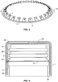
- FIG. 3 therein illustrated is a frontal view of an annular locking member (steel ring) 4 with angled teeth 6 extending from the annular base of the annular locking member 4.
- the ends of at least one angled tooth 6 lock the piping element from longitudinal movement and the jagged edges 7 prevent the piping element from rotational movement (prevent the piping element from turning).
- longitudinal and rotational movement of the annular locking member 4 is further reduced with the aid of locking tabs 12 on one or more sides of the annular locking member 4.
- the annular locking member 4, the teeth 6, jagged edges 7 and locking tabs 12 can be made of any hard material that is non corrosive.
- they can be made of stainless steel.
- a cross-sectional view of the end cap 1 enclosing a receiving member The end cap 1 may be fabricated in different ways but are illustrated here for example as a two-cavity mold (2 half portions of the receiving member) that when combined together form the annular grooves 16 (here two grooves can be observed) as well as the locking grooves (indents) 18. Further, it can be seen in Fig. 4 that a chamber 27 is formed in the receiving member to fit the annular base of the annular locking member 4 therein.
- the receiving member also comprises an angular portion 9. When in use, the teeth 6 are pushed against this angular portion 9 by the beveled portion 15 of the annular releasing member (as shown in Fig. 5 and 6 ).
- the end cap enclosing a receiving member as shown in Fig. 4 , it is also shown that the bottom of the beveled portion of the annular releasing member abuts against the ledge 17.
- a retaining shoulder can be used.
- a second chamber is formed in the receiving member. The beveled portion sits in this second chamber. In this example, one side of the beveled portion (the wider portion) abuts against the ledge projecting from the second chamber and the other side of the beveled portion (the narrower portion) abuts against the annular locking member 4.
- the end cap enclosing a retaining member comprises female edges (slots) 22 and male edges (parts) 24 that can be securely coupled to one another. This overcomes the need to fuse or glue together the parts and allows joining both sides of the plumbing fitting 1. As a result, the two parts are integrally molded.
- FIG. 5 and 6 therein illustrated are views of the end cap 1 enclosing a receiving member and more particularly showing the female indent (or edge) 22, male part (or edge) 24, the annular grooves 16 , the locking grooves 18 for the locking tabs 12, the angular portion 9 of the receiving member, the first chamber 27 for receiving the annular base of the annular locking member 4 and the ledge 17 projecting from the second chamber that serves to secure the annular releasing member (release collar) 5.
- the annular releasing member 5 comprises a beveled portion 15 that, when is use, is pushed up by the pressing of the L-shaped flanged end 14 to release the teeth 6, 7 which are pressed towards the angular portion 9 of the receiving member.
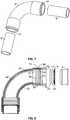
- FIG. 7 therein illustrated is a perspective view of an elbow fitting 2.
- any other type of fitting such as (45, TY, Y, coupling, etc.) that are suitable for drains, waste or vent systems and also for central systems can be used.
- These fittings are also suitable for use in medical systems and medical devices as well as in HVAC systems (Heating, Ventilating/Ventilation, and Air Conditioning).
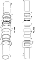
- Fig. 8 and 9 therein illustrated are exploded cross-sectional views of an elbow fitting 2 and its components. In particular, it can be seen in Fig.
- the receiving member can be placed at either extremity of the fitting body 2.
- Any other type of fitting such as a 45 fitting, TY fitting, Y fitting, coupling, etc. that are used for drains, waste pipe, pool lines or vent systems and also central systems can be used.
- a shoulder 31 that will ensure an even flow without any chance of blockage in the plumbing fitting.
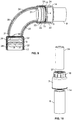
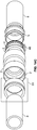
- a trap adapter 3 comprising a tail piece 34, a piping element 8, a nut 19 and a nylon washer 37 with the annular releasing member 14.
- FIG. 11, 12 therein illustrated is a cross-sectional exploded view of a trap adapter 3 showing the female edge 22, male edge 24, the annular grooves 16, the locking grooves 18, the angular portion 9 of the receiving member and the chamber 27 that will receive the annular base of the annular locking member 4. Also shown is the ledge 17 for securing the annular releasing member 5.
- the annular releasing member 5 comprises a beveled portion 15 that when pushed up by the user by pressing the flanged end 14, releases the teeth 6,7 thus releasing the piping element 8.
- Fig. 11, 12 also show that after inserting the tail piece 34 in the trap adapter 3, a nut 19 is screwed onto the male adapter 26 and is tightened by the nylon washer 37 to prevent leakage on the tail piece 34. Also shown is a shoulder in the fitting 31 to ensure an even flow without any chance of blockage in the plumbing fitting.
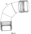
- Fig. 13 shows a fitting having a slidable or retractable portion 99 that can be moved to select a given angle.
- This expandable fitting thus has this movable portion that acts as a telescopic portion that is configured to adopt a desired angle.
- This fitting is thus versatile and can be adjusted, for example, to adopt any angle of 0 to 90 degrees. For example, it can be a 45 or 90 degrees angle.
- the fitting is made of a male1female configuration, a male portion being slidably inserted into the female portion. Therefore, by sliding the portions (top and bottom) with respect to one another, the user can select the angle that will be adopted by the fitting.
- Figs. 14A, 14B and 14C there is provided another example.
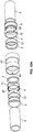
- the straight fitting 47 of Figs. 14A, 14B and 14C is similar to those presented in Figs. 7-9 but has some particularities. In fact, it has only one seal at each end. Moreover, it comprises a receiving element 46 for receiving the annular locking member 4. The annular releasing member 5 is also inserted into the receiving element 46 so as to form the combination 55. Once the seal 2 is introduced in the housing 47, the receiving element 46 having the locking member 4 and the releasing member 5 inserted therein can be inserted in the receiving member (more particularly the first chamber of the receiving member). That is eventually done at both ends of the housing 47 that has two receiving members. Then, the fitting is ready to be used and receive at both ends a piping element 8.
- the receiving element 46 is shown as having the locking member 4 and the releasing member 5 inserted therein (the combination 55), while on the right side, the received element 46 is show as having the locking member 4 inserted therein, but as being distant from the releasing member 5.
- the combination 55 can also be glued or soldered into the housing 7 in various manners.
- Figs. 14A, 14B and 14C allows for avoiding to connect together two portions or two halves of a receiving member (for example by using ultrasonic welding).
- the fitting of Figs. 14A, 14B and 14C can be manufactured.
- the plumbing fitting of Figs. 14A, 14B and 14C can comprise members that are all made of a single piece.
- the receiving element 46 can also have at least one a seal inserted therein.
- the seal 2 in introduced into the coupling or fitting 47.
- the spacer 51 is inserted into the coupling or fitting 47.
- Such a spacer is used to maintain or urge the teeth of the locking member 4 inwardly. This allows for maintaining the plumbing fitting efficient even after several uses.
- the locking member 4 is then inserted into 47 and the receiving element 72 (squeeze cup) squeezes the locking member 4, the spacer 51 and the seal 2 into the fitting or coupling 47.
- the receiving element 72 also comprises at least one nipple 57 that is effective for locking it into the matching groove or recess 63 formed into the fitting or coupling 47.
- the recess or grove 63 could alternatively be a slot that is defined in the entire thickness of the fitting 47.
- the spacer 51 can be made of any type of hard plastic or rubber so that the teeth of the locking member 4 can have a spring back reaction.
- the receiving element 72 squeezes 4, 51 and 2 to it place in 47 having 57 following the slot and then at the end a small twist will lock the receiving element 72 as well as 4, 51 and 2 into place.
- the receiving element 72 can be glued into 47, and in such a case does not require the nipple 57 and matching groove or recess 63.
- the releasing member 5 is pushed or snapped into 72 at the end.
- the seal 2 can be any type of seal that is used to code.
- Fig. 15B is a cross section of Fig. 15A with the exception of the seal 23 that replaces the seal 2 of Fig. 15A .
- the seal 23 can be of any shape, form or any material needed to create a seal with the pipe.
- the fitting 1 is at one end 23 being a o-ring (or any other type of seal)
- the spacer 51 between the seal 23 and 4 having a bevel in it for the locking member 4 to set on and can be made of any type of hard plastic or rubber so that the teeth can have a spring back reaction
- the receiving element 61 being a squeeze cup that squeezes locking member 4, spacer 51 and seal 23 into its place in fitting 1.
- the element 56 being the lock ring that is glued on fitting 1 at the end to hold 61 in place.
- the releasing member 5 being the release collar that is snapped into 61.
- the element 56 may not be needed if found that gluing or a snapping system of 61 is a better option.
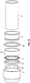
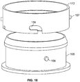
- Figs. 17 and 18 there is shown a different version the releasing member 105 comprising a nipple 158 dimensioned to enter into slot 159 of the receiving element 172.
- the receiving element 172 comprises a nipple 157 adapted to be inserted into a slot shown at the bottom left part of fitting 147.
- the locking member 4, the spacer 51 and the seal 2 are as discussed regarding Fig. 15A .
- Fig. 17 see left side
- the nipple 159 is inserted into slot 161.
- a user can simply turn releasing member (see releasing member at left part of Fig. 17 ) upwardly to more back nipple 159 into slot 160 (rather than slot 161) and then push the releasing member 105 toward fitting 147 to urges the teeth of the annular locking member 5 outwardly and disengage the piping by pulling it outside of all constituents105, 172, 4, 51, 2 and 147.
- any other type of fitting such as (45, TY, Y, coupling, etc.) can be used rather than the straight fitting shown in Figs. 14A, 14B 14C , 15A , 15B , 16 , 17 and 18 .
- a fitting can be ABS or PVC or any other type of DWV, HVAC or medical pipe being used for that purpose. It can be suitable for drains, waste or vent systems and also for central systems can be used.
- the fitting can be suitable for use in medical systems and medical devices as well as in HVAC systems (Heating, Ventilating/Ventilation, and Air Conditioning).
- fitting and methods of the present disclosure are very useful since can avoid using ABS glue or PVC glue or primers that can be required before applying a glue.
- thyn can be assembled without the use of plumbing tools. That can also be used without requiring a precise straight alignment (like conventional plumbing fittings). In conventional plumbing fitting, if the alignment is not almost perfectly straight, this may result in water leaking. Also, the fitting, allow for a rotation of the piping into the fitting. Glued conventional piping members and fittings cannot rotate with respect to one another. Also a user can easily disassemble a piping from a fitting by pressing the release member and rapidly reintroduce it. That cannot be done with a conventional glued piping and fitting combination. A lot of wasted time and material can be saved by using the fitting and methods of the present disclosure.
Landscapes
- Engineering & Computer Science (AREA)
- General Engineering & Computer Science (AREA)
- Mechanical Engineering (AREA)
- Quick-Acting Or Multi-Walled Pipe Joints (AREA)
- Joints With Sleeves (AREA)
- Sink And Installation For Waste Water (AREA)
Applications Claiming Priority (5)
| Application Number | Priority Date | Filing Date | Title |
|---|---|---|---|
| US201662369119P | 2016-07-31 | 2016-07-31 | |
| US201662376942P | 2016-08-19 | 2016-08-19 | |
| US201762474043P | 2017-03-20 | 2017-03-20 | |
| US201762482721P | 2017-04-07 | 2017-04-07 | |
| PCT/CA2017/050919 WO2018023196A1 (en) | 2016-07-31 | 2017-07-31 | Plumbing fittings |
Publications (3)
| Publication Number | Publication Date |
|---|---|
| EP3491280A1 EP3491280A1 (en) | 2019-06-05 |
| EP3491280A4 EP3491280A4 (en) | 2019-06-05 |
| EP3491280B1 true EP3491280B1 (en) | 2021-10-13 |
Family
ID=61072146
Family Applications (1)
| Application Number | Title | Priority Date | Filing Date |
|---|---|---|---|
| EP17836122.6A Active EP3491280B1 (en) | 2016-07-31 | 2017-07-31 | Plumbing fitting |
Country Status (9)
| Country | Link |
|---|---|
| US (1) | US11204118B2 (ja) |
| EP (1) | EP3491280B1 (ja) |
| JP (1) | JP2019523380A (ja) |
| CN (2) | CN109923341A (ja) |
| AU (1) | AU2017306587A1 (ja) |
| CA (1) | CA3032204C (ja) |
| ES (1) | ES2903477T3 (ja) |
| MX (1) | MX2019001338A (ja) |
| WO (1) | WO2018023196A1 (ja) |
Families Citing this family (7)
| Publication number | Priority date | Publication date | Assignee | Title |
|---|---|---|---|---|
| SE542546C2 (en) * | 2017-09-11 | 2020-06-02 | Scan Coin Ab | A coin handling apparatus |
| GB201808394D0 (en) * | 2018-05-22 | 2018-07-11 | Polypipe Ltd | Plumbing fitting |
| US11560967B2 (en) | 2018-09-04 | 2023-01-24 | Brasscraft Manufacturing Company | Rotation-resistant push-on conduit coupling cartridge |
| JP7326888B2 (ja) * | 2019-06-05 | 2023-08-16 | 株式会社オンダ製作所 | 継手 |
| WO2021042214A1 (en) * | 2019-09-05 | 2021-03-11 | 9352-4585 Québec Inc. | Plumbing fitting |
| EP3842678A1 (en) * | 2019-12-26 | 2021-06-30 | Hsin Cheng Kuo | Tube connector |
| US20220178480A1 (en) * | 2020-12-05 | 2022-06-09 | Jacob FRIEDRICH | Releasing device for disconnecting a pipe off of a fitting body |
Family Cites Families (34)
| Publication number | Priority date | Publication date | Assignee | Title |
|---|---|---|---|---|
| JPH073119Y2 (ja) | 1989-11-20 | 1995-01-30 | シーケーディ株式会社 | 管継手 |
| FR2702818B1 (fr) * | 1993-03-19 | 1995-06-02 | Legris Sa | Raccord à connexion instantanée à griffe. |
| US6059192A (en) | 1996-04-04 | 2000-05-09 | Zosimadis; Peter | Wireless temperature monitoring system |
| JP2001159486A (ja) * | 1997-04-12 | 2001-06-12 | Bridgestone Corp | パイプ継手のソケット構造 |
| JP3054103B2 (ja) | 1997-04-28 | 2000-06-19 | 秀三郎 石井 | 管部材の接続栓装置 |
| JP4213303B2 (ja) | 1999-07-22 | 2009-01-21 | 株式会社パイオラックス | 管継手 |
| FR2830071B1 (fr) | 2001-09-21 | 2003-11-14 | Legris Sa | Dispositif de raccordement instantane |
| NL1029412C2 (nl) | 2005-07-03 | 2007-01-08 | Widee Bv | Koppeling tussen twee lichamen. |
| JP4701068B2 (ja) * | 2005-10-21 | 2011-06-15 | ブリヂストンフローテック株式会社 | 管継手 |
| KR100749318B1 (ko) | 2006-12-19 | 2007-08-14 | 세창인스트루먼트(주) | 수도관의 최적의 수질측정 및 알림장치 및 그 방법 |
| US9266136B2 (en) | 2007-10-24 | 2016-02-23 | Michael Klicpera | Apparatus for displaying, monitoring and/or controlling shower, bath or sink faucet water parameters with an audio or verbal annunciations or control means |
| US7530606B1 (en) | 2008-01-04 | 2009-05-12 | Richard Yang | Quick pipe connector |
| CN101329001A (zh) * | 2008-07-11 | 2008-12-24 | 安业环球有限公司 | 流体管连接装置内齿卡环 |
| CN201262294Y (zh) | 2008-08-04 | 2009-06-24 | 浙江兴鑫爱特铜业有限公司 | 新型的管子快速连接结构 |
| CN201382226Y (zh) | 2009-01-23 | 2010-01-13 | 玉环江林水暖管业有限公司 | 快速接头 |
| FR2943696B1 (fr) | 2009-03-24 | 2016-08-26 | Veolia Eau - Cie Generale Des Eaux | Installation et procede de controle de la qualite de l'eau dans un reseau d'eau potable |
| US9523454B2 (en) * | 2009-10-21 | 2016-12-20 | Brasscraft Manufacturing Company | Anti-rotation gripper ring |
| FR2946117B1 (fr) * | 2010-05-11 | 2013-03-08 | Legris Sas | Dispositif de raccordement de tubes de protection d'un cable a fibres optiques et troncon d'un circuit de transmission optique comportant un tel dispositif |
| FR2961885B1 (fr) * | 2010-06-29 | 2012-07-13 | Parker Hannifin France Sas | Insert de raccord instantane |
| US8398122B2 (en) * | 2010-12-30 | 2013-03-19 | Quick Fitting, Inc. | Push connect joint assembly, system and method |
| KR20120079439A (ko) | 2011-01-04 | 2012-07-12 | 나리스 코몰로차나폰 | 신속한 연결 파이프이음 시스템 |
| US20130181446A1 (en) * | 2012-01-13 | 2013-07-18 | Comap | Quick-connect coupler |
| US8820795B2 (en) | 2012-02-02 | 2014-09-02 | Victaulic Company | Fitting for joining pipe elements |
| JP2014092222A (ja) * | 2012-11-05 | 2014-05-19 | Bridgestone Corp | 管継手及び管継手の製造方法 |
| PL3434955T3 (pl) * | 2013-07-17 | 2021-09-20 | Victaulic Company | Kształtki mające łukowate żebra usztywniające |
| JP5546077B2 (ja) | 2013-07-18 | 2014-07-09 | 前澤給装工業株式会社 | 管継手 |
| US9777875B2 (en) * | 2014-02-26 | 2017-10-03 | Nibco Inc. | Clam shell push-to-connect assembly |
| CN105003777B (zh) * | 2014-05-30 | 2017-10-24 | 迅捷装配有限公司 | 推入式连接配合集成密封结构、装置和方法 |
| US10094500B2 (en) * | 2014-05-30 | 2018-10-09 | Quick Fitting, Inc. | Push-to-connect fitting integrated packing arrangement, device and methods |
| US9068680B1 (en) | 2014-05-30 | 2015-06-30 | Quick Fitting, Inc. | Push-to-connect fitting integrated packing arrangement, device and methods |
| CN104154363B (zh) * | 2014-08-28 | 2016-06-08 | 许道泽 | 管件快速连接装置 |
| JP2016089899A (ja) * | 2014-10-31 | 2016-05-23 | 株式会社日本ピスコ | 管継手および管継手の製造方法 |
| US9816655B2 (en) * | 2014-12-09 | 2017-11-14 | Quick Fitting, Inc. | Rotation locking push-to-connect fitting device, system and method |
| CN105318127B (zh) | 2015-12-12 | 2017-09-19 | 玉环县豪立信铜业有限公司 | 一种管子的快速连接机构 |
-
2017
- 2017-07-31 JP JP2019506154A patent/JP2019523380A/ja active Pending
- 2017-07-31 CN CN201780056060.7A patent/CN109923341A/zh active Pending
- 2017-07-31 WO PCT/CA2017/050919 patent/WO2018023196A1/en unknown
- 2017-07-31 ES ES17836122T patent/ES2903477T3/es active Active
- 2017-07-31 US US16/321,842 patent/US11204118B2/en active Active
- 2017-07-31 EP EP17836122.6A patent/EP3491280B1/en active Active
- 2017-07-31 MX MX2019001338A patent/MX2019001338A/es unknown
- 2017-07-31 CN CN202211009122.8A patent/CN115405776A/zh active Pending
- 2017-07-31 AU AU2017306587A patent/AU2017306587A1/en not_active Abandoned
- 2017-07-31 CA CA3032204A patent/CA3032204C/en active Active
Non-Patent Citations (1)
| Title |
|---|
| None * |
Also Published As
| Publication number | Publication date |
|---|---|
| CN115405776A (zh) | 2022-11-29 |
| ES2903477T3 (es) | 2022-04-01 |
| EP3491280A1 (en) | 2019-06-05 |
| WO2018023196A1 (en) | 2018-02-08 |
| AU2017306587A1 (en) | 2019-03-21 |
| US11204118B2 (en) | 2021-12-21 |
| MX2019001338A (es) | 2019-05-15 |
| CA3032204C (en) | 2023-02-14 |
| CA3032204A1 (en) | 2018-02-08 |
| US20190162344A1 (en) | 2019-05-30 |
| CN109923341A (zh) | 2019-06-21 |
| EP3491280A4 (en) | 2019-06-05 |
| JP2019523380A (ja) | 2019-08-22 |
Similar Documents
| Publication | Publication Date | Title |
|---|---|---|
| EP3491280B1 (en) | Plumbing fitting | |
| EP3084280B1 (en) | Pipe connection fitting | |
| EP3350497B1 (en) | Push-to-connect joint assembly with protective shield device and method | |
| CN109642688B (zh) | 混合推入连接式配合装置和组件 | |
| CA2928743C (en) | Push-to-connect fitting | |
| EP3221627B1 (en) | Quick connector assembly | |
| US8888145B1 (en) | Press fitting device, components and method | |
| US9574691B1 (en) | Hybrid push-to-connect fitting device, arrangement and method | |
| US9822912B2 (en) | Push-to-connect fitting device, arrangement and method | |
| WO2015187958A1 (en) | Compression fitting with torque nut | |
| US6877777B1 (en) | Insertion sleeve and stiffener for a pipe coupling | |
| US20070018450A1 (en) | Fitting assembly for internally sealing a corrugated tube and a method for using the same | |
| US20090208271A1 (en) | Modular coupling system | |
| EP3055599B1 (en) | Press fitting device and method | |
| US20130187380A1 (en) | Push-on Tubing Coupler with Triple Seal and Adapter | |
| NZ714700A (en) | (+)-5-(3,4-difluorophenyl)-5-[(3-methyl-2-oxopyridin-1(2h)-yl)methyl]imidazolidine-2,4-dione and drug containing same | |
| US20070018449A1 (en) | Fitting assembly for deformably sealing corrugated tubing and a method for using the same | |
| US20160053923A1 (en) | Push-on Tubing Coupler with Triple Seal and Adapter | |
| WO2021042214A1 (en) | Plumbing fitting | |
| WO2004061351A2 (en) | Integrally housed tube insert |
Legal Events
| Date | Code | Title | Description |
|---|---|---|---|
| STAA | Information on the status of an ep patent application or granted ep patent |
Free format text: STATUS: THE INTERNATIONAL PUBLICATION HAS BEEN MADE |
|
| PUAI | Public reference made under article 153(3) epc to a published international application that has entered the european phase |
Free format text: ORIGINAL CODE: 0009012 |
|
| STAA | Information on the status of an ep patent application or granted ep patent |
Free format text: STATUS: REQUEST FOR EXAMINATION WAS MADE |
|
| 17P | Request for examination filed |
Effective date: 20190228 |
|
| A4 | Supplementary search report drawn up and despatched |
Effective date: 20190423 |
|
| AK | Designated contracting states |
Kind code of ref document: A1 Designated state(s): AL AT BE BG CH CY CZ DE DK EE ES FI FR GB GR HR HU IE IS IT LI LT LU LV MC MK MT NL NO PL PT RO RS SE SI SK SM TR |
|
| AX | Request for extension of the european patent |
Extension state: BA ME |
|
| DAV | Request for validation of the european patent (deleted) | ||
| DAX | Request for extension of the european patent (deleted) | ||
| STAA | Information on the status of an ep patent application or granted ep patent |
Free format text: STATUS: EXAMINATION IS IN PROGRESS |
|
| 17Q | First examination report despatched |
Effective date: 20200511 |
|
| STAA | Information on the status of an ep patent application or granted ep patent |
Free format text: STATUS: EXAMINATION IS IN PROGRESS |
|
| GRAP | Despatch of communication of intention to grant a patent |
Free format text: ORIGINAL CODE: EPIDOSNIGR1 |
|
| STAA | Information on the status of an ep patent application or granted ep patent |
Free format text: STATUS: GRANT OF PATENT IS INTENDED |
|
| RIC1 | Information provided on ipc code assigned before grant |
Ipc: F16L 37/091 20060101AFI20210408BHEP Ipc: F16L 27/12 20060101ALI20210408BHEP |
|
| INTG | Intention to grant announced |
Effective date: 20210503 |
|
| GRAS | Grant fee paid |
Free format text: ORIGINAL CODE: EPIDOSNIGR3 |
|
| GRAA | (expected) grant |
Free format text: ORIGINAL CODE: 0009210 |
|
| STAA | Information on the status of an ep patent application or granted ep patent |
Free format text: STATUS: THE PATENT HAS BEEN GRANTED |
|
| AK | Designated contracting states |
Kind code of ref document: B1 Designated state(s): AL AT BE BG CH CY CZ DE DK EE ES FI FR GB GR HR HU IE IS IT LI LT LU LV MC MK MT NL NO PL PT RO RS SE SI SK SM TR |
|
| REG | Reference to a national code |
Ref country code: GB Ref legal event code: FG4D |
|
| REG | Reference to a national code |
Ref country code: CH Ref legal event code: EP |
|
| REG | Reference to a national code |
Ref country code: DE Ref legal event code: R096 Ref document number: 602017047694 Country of ref document: DE |
|
| REG | Reference to a national code |
Ref country code: IE Ref legal event code: FG4D |
|
| REG | Reference to a national code |
Ref country code: AT Ref legal event code: REF Ref document number: 1438430 Country of ref document: AT Kind code of ref document: T Effective date: 20211115 |
|
| REG | Reference to a national code |
Ref country code: NL Ref legal event code: FP |
|
| REG | Reference to a national code |
Ref country code: LT Ref legal event code: MG9D |
|
| REG | Reference to a national code |
Ref country code: AT Ref legal event code: MK05 Ref document number: 1438430 Country of ref document: AT Kind code of ref document: T Effective date: 20211013 |
|
| REG | Reference to a national code |
Ref country code: ES Ref legal event code: FG2A Ref document number: 2903477 Country of ref document: ES Kind code of ref document: T3 Effective date: 20220401 |
|
| PG25 | Lapsed in a contracting state [announced via postgrant information from national office to epo] |
Ref country code: RS Free format text: LAPSE BECAUSE OF FAILURE TO SUBMIT A TRANSLATION OF THE DESCRIPTION OR TO PAY THE FEE WITHIN THE PRESCRIBED TIME-LIMIT Effective date: 20211013 Ref country code: LT Free format text: LAPSE BECAUSE OF FAILURE TO SUBMIT A TRANSLATION OF THE DESCRIPTION OR TO PAY THE FEE WITHIN THE PRESCRIBED TIME-LIMIT Effective date: 20211013 Ref country code: FI Free format text: LAPSE BECAUSE OF FAILURE TO SUBMIT A TRANSLATION OF THE DESCRIPTION OR TO PAY THE FEE WITHIN THE PRESCRIBED TIME-LIMIT Effective date: 20211013 Ref country code: BG Free format text: LAPSE BECAUSE OF FAILURE TO SUBMIT A TRANSLATION OF THE DESCRIPTION OR TO PAY THE FEE WITHIN THE PRESCRIBED TIME-LIMIT Effective date: 20220113 Ref country code: AT Free format text: LAPSE BECAUSE OF FAILURE TO SUBMIT A TRANSLATION OF THE DESCRIPTION OR TO PAY THE FEE WITHIN THE PRESCRIBED TIME-LIMIT Effective date: 20211013 |
|
| PG25 | Lapsed in a contracting state [announced via postgrant information from national office to epo] |
Ref country code: IS Free format text: LAPSE BECAUSE OF FAILURE TO SUBMIT A TRANSLATION OF THE DESCRIPTION OR TO PAY THE FEE WITHIN THE PRESCRIBED TIME-LIMIT Effective date: 20220213 Ref country code: SE Free format text: LAPSE BECAUSE OF FAILURE TO SUBMIT A TRANSLATION OF THE DESCRIPTION OR TO PAY THE FEE WITHIN THE PRESCRIBED TIME-LIMIT Effective date: 20211013 Ref country code: PT Free format text: LAPSE BECAUSE OF FAILURE TO SUBMIT A TRANSLATION OF THE DESCRIPTION OR TO PAY THE FEE WITHIN THE PRESCRIBED TIME-LIMIT Effective date: 20220214 Ref country code: PL Free format text: LAPSE BECAUSE OF FAILURE TO SUBMIT A TRANSLATION OF THE DESCRIPTION OR TO PAY THE FEE WITHIN THE PRESCRIBED TIME-LIMIT Effective date: 20211013 Ref country code: NO Free format text: LAPSE BECAUSE OF FAILURE TO SUBMIT A TRANSLATION OF THE DESCRIPTION OR TO PAY THE FEE WITHIN THE PRESCRIBED TIME-LIMIT Effective date: 20220113 Ref country code: LV Free format text: LAPSE BECAUSE OF FAILURE TO SUBMIT A TRANSLATION OF THE DESCRIPTION OR TO PAY THE FEE WITHIN THE PRESCRIBED TIME-LIMIT Effective date: 20211013 Ref country code: HR Free format text: LAPSE BECAUSE OF FAILURE TO SUBMIT A TRANSLATION OF THE DESCRIPTION OR TO PAY THE FEE WITHIN THE PRESCRIBED TIME-LIMIT Effective date: 20211013 Ref country code: GR Free format text: LAPSE BECAUSE OF FAILURE TO SUBMIT A TRANSLATION OF THE DESCRIPTION OR TO PAY THE FEE WITHIN THE PRESCRIBED TIME-LIMIT Effective date: 20220114 |
|
| REG | Reference to a national code |
Ref country code: DE Ref legal event code: R097 Ref document number: 602017047694 Country of ref document: DE |
|
| PG25 | Lapsed in a contracting state [announced via postgrant information from national office to epo] |
Ref country code: SM Free format text: LAPSE BECAUSE OF FAILURE TO SUBMIT A TRANSLATION OF THE DESCRIPTION OR TO PAY THE FEE WITHIN THE PRESCRIBED TIME-LIMIT Effective date: 20211013 Ref country code: SK Free format text: LAPSE BECAUSE OF FAILURE TO SUBMIT A TRANSLATION OF THE DESCRIPTION OR TO PAY THE FEE WITHIN THE PRESCRIBED TIME-LIMIT Effective date: 20211013 Ref country code: RO Free format text: LAPSE BECAUSE OF FAILURE TO SUBMIT A TRANSLATION OF THE DESCRIPTION OR TO PAY THE FEE WITHIN THE PRESCRIBED TIME-LIMIT Effective date: 20211013 Ref country code: EE Free format text: LAPSE BECAUSE OF FAILURE TO SUBMIT A TRANSLATION OF THE DESCRIPTION OR TO PAY THE FEE WITHIN THE PRESCRIBED TIME-LIMIT Effective date: 20211013 Ref country code: DK Free format text: LAPSE BECAUSE OF FAILURE TO SUBMIT A TRANSLATION OF THE DESCRIPTION OR TO PAY THE FEE WITHIN THE PRESCRIBED TIME-LIMIT Effective date: 20211013 Ref country code: CZ Free format text: LAPSE BECAUSE OF FAILURE TO SUBMIT A TRANSLATION OF THE DESCRIPTION OR TO PAY THE FEE WITHIN THE PRESCRIBED TIME-LIMIT Effective date: 20211013 |
|
| PLBE | No opposition filed within time limit |
Free format text: ORIGINAL CODE: 0009261 |
|
| STAA | Information on the status of an ep patent application or granted ep patent |
Free format text: STATUS: NO OPPOSITION FILED WITHIN TIME LIMIT |
|
| 26N | No opposition filed |
Effective date: 20220714 |
|
| PGFP | Annual fee paid to national office [announced via postgrant information from national office to epo] |
Ref country code: NL Payment date: 20220801 Year of fee payment: 6 |
|
| PG25 | Lapsed in a contracting state [announced via postgrant information from national office to epo] |
Ref country code: AL Free format text: LAPSE BECAUSE OF FAILURE TO SUBMIT A TRANSLATION OF THE DESCRIPTION OR TO PAY THE FEE WITHIN THE PRESCRIBED TIME-LIMIT Effective date: 20211013 |
|
| PGFP | Annual fee paid to national office [announced via postgrant information from national office to epo] |
Ref country code: IT Payment date: 20220801 Year of fee payment: 6 Ref country code: GB Payment date: 20220801 Year of fee payment: 6 Ref country code: ES Payment date: 20220805 Year of fee payment: 6 Ref country code: DE Payment date: 20220808 Year of fee payment: 6 |
|
| PG25 | Lapsed in a contracting state [announced via postgrant information from national office to epo] |
Ref country code: SI Free format text: LAPSE BECAUSE OF FAILURE TO SUBMIT A TRANSLATION OF THE DESCRIPTION OR TO PAY THE FEE WITHIN THE PRESCRIBED TIME-LIMIT Effective date: 20211013 |
|
| PGFP | Annual fee paid to national office [announced via postgrant information from national office to epo] |
Ref country code: FR Payment date: 20220801 Year of fee payment: 6 Ref country code: BE Payment date: 20220801 Year of fee payment: 6 |
|
| PGFP | Annual fee paid to national office [announced via postgrant information from national office to epo] |
Ref country code: CH Payment date: 20220803 Year of fee payment: 6 |
|
| PG25 | Lapsed in a contracting state [announced via postgrant information from national office to epo] |
Ref country code: MC Free format text: LAPSE BECAUSE OF FAILURE TO SUBMIT A TRANSLATION OF THE DESCRIPTION OR TO PAY THE FEE WITHIN THE PRESCRIBED TIME-LIMIT Effective date: 20211013 |
|
| PG25 | Lapsed in a contracting state [announced via postgrant information from national office to epo] |
Ref country code: LU Free format text: LAPSE BECAUSE OF NON-PAYMENT OF DUE FEES Effective date: 20220731 |
|
| PG25 | Lapsed in a contracting state [announced via postgrant information from national office to epo] |
Ref country code: IE Free format text: LAPSE BECAUSE OF NON-PAYMENT OF DUE FEES Effective date: 20220731 |
|
| REG | Reference to a national code |
Ref country code: DE Ref legal event code: R119 Ref document number: 602017047694 Country of ref document: DE |
|
| REG | Reference to a national code |
Ref country code: CH Ref legal event code: PL |
|
| REG | Reference to a national code |
Ref country code: NL Ref legal event code: MM Effective date: 20230801 |
|
| REG | Reference to a national code |
Ref country code: BE Ref legal event code: MM Effective date: 20230731 |
|
| GBPC | Gb: european patent ceased through non-payment of renewal fee |
Effective date: 20230731 |
|
| PG25 | Lapsed in a contracting state [announced via postgrant information from national office to epo] |
Ref country code: HU Free format text: LAPSE BECAUSE OF FAILURE TO SUBMIT A TRANSLATION OF THE DESCRIPTION OR TO PAY THE FEE WITHIN THE PRESCRIBED TIME-LIMIT; INVALID AB INITIO Effective date: 20170731 |
|
| PG25 | Lapsed in a contracting state [announced via postgrant information from national office to epo] |
Ref country code: NL Free format text: LAPSE BECAUSE OF NON-PAYMENT OF DUE FEES Effective date: 20230801 |
|
| PG25 | Lapsed in a contracting state [announced via postgrant information from national office to epo] |
Ref country code: NL Free format text: LAPSE BECAUSE OF NON-PAYMENT OF DUE FEES Effective date: 20230801 Ref country code: MK Free format text: LAPSE BECAUSE OF FAILURE TO SUBMIT A TRANSLATION OF THE DESCRIPTION OR TO PAY THE FEE WITHIN THE PRESCRIBED TIME-LIMIT Effective date: 20211013 Ref country code: DE Free format text: LAPSE BECAUSE OF NON-PAYMENT OF DUE FEES Effective date: 20240201 Ref country code: CY Free format text: LAPSE BECAUSE OF FAILURE TO SUBMIT A TRANSLATION OF THE DESCRIPTION OR TO PAY THE FEE WITHIN THE PRESCRIBED TIME-LIMIT Effective date: 20211013 Ref country code: GB Free format text: LAPSE BECAUSE OF NON-PAYMENT OF DUE FEES Effective date: 20230731 Ref country code: CH Free format text: LAPSE BECAUSE OF NON-PAYMENT OF DUE FEES Effective date: 20230731 |