EP3490856B1 - Hydraulische fahrzeugbremsanlage - Google Patents
Hydraulische fahrzeugbremsanlage Download PDFInfo
- Publication number
- EP3490856B1 EP3490856B1 EP17730703.0A EP17730703A EP3490856B1 EP 3490856 B1 EP3490856 B1 EP 3490856B1 EP 17730703 A EP17730703 A EP 17730703A EP 3490856 B1 EP3490856 B1 EP 3490856B1
- Authority
- EP
- European Patent Office
- Prior art keywords
- brake
- vehicle
- unit
- pedal
- wheel
- Prior art date
- Legal status (The legal status is an assumption and is not a legal conclusion. Google has not performed a legal analysis and makes no representation as to the accuracy of the status listed.)
- Active
Links
Images
Classifications
-
- B—PERFORMING OPERATIONS; TRANSPORTING
- B60—VEHICLES IN GENERAL
- B60T—VEHICLE BRAKE CONTROL SYSTEMS OR PARTS THEREOF; BRAKE CONTROL SYSTEMS OR PARTS THEREOF, IN GENERAL; ARRANGEMENT OF BRAKING ELEMENTS ON VEHICLES IN GENERAL; PORTABLE DEVICES FOR PREVENTING UNWANTED MOVEMENT OF VEHICLES; VEHICLE MODIFICATIONS TO FACILITATE COOLING OF BRAKES
- B60T13/00—Transmitting braking action from initiating means to ultimate brake actuator with power assistance or drive; Brake systems incorporating such transmitting means, e.g. air-pressure brake systems
- B60T13/10—Transmitting braking action from initiating means to ultimate brake actuator with power assistance or drive; Brake systems incorporating such transmitting means, e.g. air-pressure brake systems with fluid assistance, drive, or release
- B60T13/58—Combined or convertible systems
- B60T13/62—Combined or convertible systems both straight and automatic
-
- B—PERFORMING OPERATIONS; TRANSPORTING
- B60—VEHICLES IN GENERAL
- B60T—VEHICLE BRAKE CONTROL SYSTEMS OR PARTS THEREOF; BRAKE CONTROL SYSTEMS OR PARTS THEREOF, IN GENERAL; ARRANGEMENT OF BRAKING ELEMENTS ON VEHICLES IN GENERAL; PORTABLE DEVICES FOR PREVENTING UNWANTED MOVEMENT OF VEHICLES; VEHICLE MODIFICATIONS TO FACILITATE COOLING OF BRAKES
- B60T8/00—Arrangements for adjusting wheel-braking force to meet varying vehicular or ground-surface conditions, e.g. limiting or varying distribution of braking force
- B60T8/32—Arrangements for adjusting wheel-braking force to meet varying vehicular or ground-surface conditions, e.g. limiting or varying distribution of braking force responsive to a speed condition, e.g. acceleration or deceleration
- B60T8/34—Arrangements for adjusting wheel-braking force to meet varying vehicular or ground-surface conditions, e.g. limiting or varying distribution of braking force responsive to a speed condition, e.g. acceleration or deceleration having a fluid pressure regulator responsive to a speed condition
- B60T8/40—Arrangements for adjusting wheel-braking force to meet varying vehicular or ground-surface conditions, e.g. limiting or varying distribution of braking force responsive to a speed condition, e.g. acceleration or deceleration having a fluid pressure regulator responsive to a speed condition comprising an additional fluid circuit including fluid pressurising means for modifying the pressure of the braking fluid, e.g. including wheel driven pumps for detecting a speed condition, or pumps which are controlled by means independent of the braking system
- B60T8/4072—Systems in which a driver input signal is used as a control signal for the additional fluid circuit which is normally used for braking
- B60T8/4081—Systems with stroke simulating devices for driver input
-
- B—PERFORMING OPERATIONS; TRANSPORTING
- B60—VEHICLES IN GENERAL
- B60T—VEHICLE BRAKE CONTROL SYSTEMS OR PARTS THEREOF; BRAKE CONTROL SYSTEMS OR PARTS THEREOF, IN GENERAL; ARRANGEMENT OF BRAKING ELEMENTS ON VEHICLES IN GENERAL; PORTABLE DEVICES FOR PREVENTING UNWANTED MOVEMENT OF VEHICLES; VEHICLE MODIFICATIONS TO FACILITATE COOLING OF BRAKES
- B60T13/00—Transmitting braking action from initiating means to ultimate brake actuator with power assistance or drive; Brake systems incorporating such transmitting means, e.g. air-pressure brake systems
- B60T13/10—Transmitting braking action from initiating means to ultimate brake actuator with power assistance or drive; Brake systems incorporating such transmitting means, e.g. air-pressure brake systems with fluid assistance, drive, or release
- B60T13/66—Electrical control in fluid-pressure brake systems
- B60T13/68—Electrical control in fluid-pressure brake systems by electrically-controlled valves
- B60T13/686—Electrical control in fluid-pressure brake systems by electrically-controlled valves in hydraulic systems or parts thereof
-
- B—PERFORMING OPERATIONS; TRANSPORTING
- B60—VEHICLES IN GENERAL
- B60T—VEHICLE BRAKE CONTROL SYSTEMS OR PARTS THEREOF; BRAKE CONTROL SYSTEMS OR PARTS THEREOF, IN GENERAL; ARRANGEMENT OF BRAKING ELEMENTS ON VEHICLES IN GENERAL; PORTABLE DEVICES FOR PREVENTING UNWANTED MOVEMENT OF VEHICLES; VEHICLE MODIFICATIONS TO FACILITATE COOLING OF BRAKES
- B60T2270/00—Further aspects of brake control systems not otherwise provided for
- B60T2270/40—Failsafe aspects of brake control systems
- B60T2270/404—Brake-by-wire or X-by-wire failsafe
-
- B—PERFORMING OPERATIONS; TRANSPORTING
- B60—VEHICLES IN GENERAL
- B60T—VEHICLE BRAKE CONTROL SYSTEMS OR PARTS THEREOF; BRAKE CONTROL SYSTEMS OR PARTS THEREOF, IN GENERAL; ARRANGEMENT OF BRAKING ELEMENTS ON VEHICLES IN GENERAL; PORTABLE DEVICES FOR PREVENTING UNWANTED MOVEMENT OF VEHICLES; VEHICLE MODIFICATIONS TO FACILITATE COOLING OF BRAKES
- B60T2270/00—Further aspects of brake control systems not otherwise provided for
- B60T2270/82—Brake-by-Wire, EHB
-
- B—PERFORMING OPERATIONS; TRANSPORTING
- B60—VEHICLES IN GENERAL
- B60T—VEHICLE BRAKE CONTROL SYSTEMS OR PARTS THEREOF; BRAKE CONTROL SYSTEMS OR PARTS THEREOF, IN GENERAL; ARRANGEMENT OF BRAKING ELEMENTS ON VEHICLES IN GENERAL; PORTABLE DEVICES FOR PREVENTING UNWANTED MOVEMENT OF VEHICLES; VEHICLE MODIFICATIONS TO FACILITATE COOLING OF BRAKES
- B60T7/00—Brake-action initiating means
- B60T7/02—Brake-action initiating means for personal initiation
- B60T7/04—Brake-action initiating means for personal initiation foot actuated
- B60T7/042—Brake-action initiating means for personal initiation foot actuated by electrical means, e.g. using travel or force sensors
-
- B—PERFORMING OPERATIONS; TRANSPORTING
- B60—VEHICLES IN GENERAL
- B60T—VEHICLE BRAKE CONTROL SYSTEMS OR PARTS THEREOF; BRAKE CONTROL SYSTEMS OR PARTS THEREOF, IN GENERAL; ARRANGEMENT OF BRAKING ELEMENTS ON VEHICLES IN GENERAL; PORTABLE DEVICES FOR PREVENTING UNWANTED MOVEMENT OF VEHICLES; VEHICLE MODIFICATIONS TO FACILITATE COOLING OF BRAKES
- B60T8/00—Arrangements for adjusting wheel-braking force to meet varying vehicular or ground-surface conditions, e.g. limiting or varying distribution of braking force
- B60T8/32—Arrangements for adjusting wheel-braking force to meet varying vehicular or ground-surface conditions, e.g. limiting or varying distribution of braking force responsive to a speed condition, e.g. acceleration or deceleration
- B60T8/321—Arrangements for adjusting wheel-braking force to meet varying vehicular or ground-surface conditions, e.g. limiting or varying distribution of braking force responsive to a speed condition, e.g. acceleration or deceleration deceleration
- B60T8/328—Systems sharing components with other fluid systems onboard the vehicle
-
- B—PERFORMING OPERATIONS; TRANSPORTING
- B60—VEHICLES IN GENERAL
- B60Y—INDEXING SCHEME RELATING TO ASPECTS CROSS-CUTTING VEHICLE TECHNOLOGY
- B60Y2400/00—Special features of vehicle units
- B60Y2400/81—Braking systems
Definitions
- the invention relates to a hydraulic vehicle brake system which is equipped with a pedal travel simulator.
- a hydraulic vehicle brake system which is equipped with a pedal travel simulator into which hydraulic fluid is displaced when the brake pedal is actuated.
- the brake pedal pressure exerted by the driver is measured by a sensor system and used as the basis for controlling an electric pump, by means of which a brake pressure corresponding to the pedal actuation is set.
- the EP 0 265 623 A2 discloses a hydraulic vehicle brake system with a pressure supply unit and a pedal travel simulator, a switching valve being arranged between the pressure supply unit and the pedal travel simulator. In a first switching position of the switching valve, the pedal travel simulator is decoupled, in a second switching position of the switching valve, on the other hand, the brake pedal is hydraulically connected to the pedal travel simulator; at the same time, hydraulic fluid is fed to the wheel brake units via a pump of the pressure supply unit.
- a pump motor is part of the pressure supply unit, the pressure build-up being proportional to the motor speed of the pump motor when the valve is open.
- the hydraulic vehicle brake system comprises at least one hydraulically actuatable wheel brake unit via which a braking force is generated on the wheel in question, for example with the aid of a wheel brake cylinder.
- the wheel brake unit can, for example, be assigned an inlet valve and an outlet valve or a pressure regulating valve for controlling the brake fluid to the wheel brake unit or away from it.
- the hydraulic vehicle brake system is equipped in a known manner with at least one brake pedal via which the driver requests braking force. Furthermore, the vehicle brake system is provided with a pedal travel simulator into which brake fluid is delivered when the brake pedal is operated.
- the hydraulic vehicle brake system can be equipped with exactly one brake pedal or with two brake pedals.
- a switching valve that can be adjusted between a first switching position, in which the brake pedal is connected to the pedal travel simulator and decoupled from the wheel brake unit, and a second switching position, in which the pedal travel simulator is decoupled from the brake pedal and the brake pedal with it the wheel brake unit is connected.
- a pressure supply unit such as a pressure accumulator, which has pressurized brake fluid, is also connected to the wheel brake unit via an adjustable valve.
- the adjustable valve is identical to the switching valve.
- This design enables the generation of braking force in two different operating states.
- first operating state which corresponds to the first switching position of the switching valve
- brake fluid is shifted into the pedal travel simulator, and the wheel brake unit is supplied with pressurized brake fluid from the pressure supply unit in order to generate braking force.
- second brake position which corresponds to the second switching state of the switching valve
- the pressure supply unit is decoupled from the wheel brake unit, at the same time the pedal travel simulator is decoupled from the brake pedal and the brake pedal is connected to the wheel brake unit, so that when a Actuation of the brake pedal brake fluid is passed into the wheel brake unit.
- This operating state corresponds to a direct penetration of the brake pedal on the wheel brake unit, with the pressure of the brake fluid possibly being able to be increased via a booster unit.
- the pressure supply unit represents an energy store with hydraulic fluid, which can optionally also be used for other functions in the vehicle, especially in the case of commercial vehicles, e.g. for use in agricultural machinery in off-road operation.
- a pressure supply unit can be present in an agricultural utility vehicle.
- the pressure supply unit can also be used for other functions in the vehicle.
- This design of the hydraulic vehicle brake system enables operation in which, when all electrically actuatable components of the vehicle brake system, in particular the valves, and when the pressure supply unit is functioning correctly, the switching valve is switched so that the first operating state is implemented when the wheel brake unit is applied via the pressure supply unit .
- the second operating state in which pressure is built up in the brake fluid in the wheel brake unit directly via the brake pedal, serves as a passive fallback level. Accordingly, in the de-energized state, the switching valve is advantageously in the second switching position, in which the pedal travel simulator is decoupled and the brake pedal is connected to the wheel brake unit.
- the pressure supply unit is decoupled from the wheel brake unit in the second switching position, so that the wheel brake unit is supplied with the pressurized hydraulic fluid exclusively by actuating the brake pedal, with a brake booster unit for boosting the brake pressure being provided if necessary.
- a pressure sensor for determining the hydraulic brake fluid pressure is advantageously located in at least one connecting line via which the brake fluid is conducted to the wheel brake unit. It can be expedient to additionally arrange a further pressure sensor directly on the wheel brake unit, via which the brake fluid pressure in the wheel brake unit can be determined.
- Another valve is located in the flow path between the pressure supply unit and the at least one wheel brake unit.
- the valve which is designed, for example, as a brake-by-wire valve, is in the blocking position in the de-energized state and thereby decouples the pressure supply unit from the at least one wheel brake unit.
- the vehicle brake system comprises at least two wheel brake units, each of which can optionally be assigned an inlet valve and an outlet valve or a pressure control valve, in particular on the two opposite wheels of a vehicle axle.
- the vehicle brake system comprises two brake circuits, each with at least one hydraulically actuated wheel brake unit, preferably with two wheel brake units each, with the two wheel brake units per brake circuit either on the opposite wheels on the same axle or diagonally offset on opposite axles.
- the second brake circuit is hydraulically connected to the first brake circuit. This design makes it possible to supply both brake circuits with brake fluid via the brake pedal in the second operating and switching state when the pedal travel simulator is decoupled.
- both brake circuits are also possible to provide a common pressure supply unit for both brake circuits, from which both brake circuits are supplied with the pressurized brake fluid in the first operating and switching state. It may possibly be expedient to arrange a hydraulic booster valve in the connection between the first and the second brake circuit, in which a pressure change is carried out in the second brake circuit compared to the first brake circuit, i.e. a pressure booster with a higher pressure in second brake circuit or with a pressure reduction with a lower pressure in the second brake circuit, based on the first brake circuit. This makes it possible, for example, to set different pressure levels in the first and in the second brake circuit in the second operating and switching state when the brake pedal is actuated. The same applies to only one pressure supply unit for both brake circuits, which is connected either to the first or to the second brake circuit.
- a hydraulic step-up valve can also be arranged in the connection between the brake circuits, especially in the event that hydraulic brake pressure is generated in the wheel brake units of both brake circuits in the second operating state by actuating the brake pedal becomes.
- the hydraulic step-up valve In the first operating state, when the wheel brake units are supplied via the respective pressure supply unit, the hydraulic step-up valve is preferably in a blocking position, so that the brake circuits are hydraulically separated. In this position, only the pressure from the pressure supply unit prevails in each brake circuit, which pressure can differ or also be the same.
- the additional pressure supply unit in the further brake circuit can optionally be connected to this brake circuit via a further switching valve which decouples the additional pressure supply unit from the further brake circuit in the de-energized state.
- the switching valve can be identical to the hydraulic transmission valve for connecting the second to the first circuit. In the de-energized state, the hydraulic transmission valve is switched in such a way that a flow connection between the brake circuits is open.
- the outlet valve on the at least one wheel brake unit is flow-connected to a reservoir into which the brake fluid flows when the outlet valve is open.
- the outlet valve is advantageously designed in such a way that it decouples the reservoir from the wheel brake unit in the de-energized state. This ensures that in the fallback level - the second operating state - when the brake pedal is actuated, the displaced brake fluid remains in the wheel brake unit and is not diverted into the reservoir via the outlet valve.
- brake circuits can either be connected to a common storage tank via the outlet valves or there is one storage tank per brake circuit.
- the vehicle brake system is preferably equipped with a regulating or control device for activating the adjustable components of the vehicle brake system. Signals from sensors of the vehicle brake system are processed in the regulating or control device and actuating signals for controlling the components in the vehicle brake system are generated.
- the vehicle that is equipped with the vehicle brake system according to the invention is, for example, a utility vehicle, for example a utility vehicle that can be used in off-road operation, or an agricultural vehicle, for example a tractor.
- a tendency of a wheel to lock can be continuously determined on the basis of sensor information, in particular from speed sensors, and the brake pressure level at the assigned wheel brake unit can be reduced by closing the inlet valve and opening the outlet valve. If there are several wheel brake units, the respectively assigned inlet and outlet valves can be closed and opened independently of the valves of the other wheel brake units.
- ABS anti-lock braking system
- an electronic stability program can be implemented for vehicle stabilization.
- the rotation of the vehicle around the vertical axis is determined, in particular via a rotation rate sensor, and compared with the driver's request, which can be determined from information from a steering angle sensor and the speed sensors. If there is a discrepancy between the driver's request and the actual position of the vehicle, the vehicle can be stabilized by opening or closing the inlet and outlet valves on at least one wheel brake unit, possibly on several wheel brake units.
- the Brake fluid under pressure can be used in the pressure supply unit.
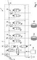
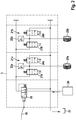
- vehicle brake system 1 shown, of which in Fig. 1 the rear axle brake circuit 2 and in Fig. 2 the front axle brake circuit 3 is shown, for example, is installed in commercial vehicles such as agricultural vehicles.
- vehicle brake system 1 comprises a brake pedal 4 which is hydraulically connected via a switching valve 5 on the one hand to a pedal travel simulator 6 and on the other hand to wheel brake units 7a, 7b on the wheels 8a, 8b of the rear axle.
- a pressure sensor 9 is located between the brake pedal 4 and the switching valve 5, and a further pressure sensor 10 is arranged in the switching valve 5 and the wheel brake units 7a, 7b. Furthermore, a pressure sensor 11a, 11b is assigned to each wheel brake unit 7a, 7b.
- Each wheel brake unit 7a, 7b has an inlet valve 12a, 12b and an outlet valve 13a, 13b on a wheel brake cylinder, brake fluid being conducted to and away from the wheel brake cylinder via the valves.
- the outlet valves 13a, 13b are connected via a common return line to a storage container 14, in which, as indicated by the arrow, at brake fluid flows back when the outlet valve is open.
- a valve 15 is arranged in the return line, which is in its blocking position in the de-energized state and interrupts the return flow to the storage container 14.
- the vehicle brake system 1 is also assigned a pressure supply unit 16 with pressurized brake fluid, which is connected to the switching valve 5 via a brake-by-wire valve 17.
- the brake-by-wire valve 17 In the de-energized state, the brake-by-wire valve 17 is in its blocking position, which interrupts the flow of flow from the pressure supply unit 16, and in the energized state, in the open position that enables the flow of flow, in which, via the switching valve 5, there is a flow connection from the pressure supply unit 16 to the wheel brake units 7a , 7b is made possible.
- the switching valve 5 In the de-energized state, the switching valve 5 is in a position decoupling the pedal travel simulator 6, the brake pedal 4 being connected to the wheel brake units 7a, 7b at the same time.
- the switching valve In the energized state, however, the switching valve is in a switching position in which the pedal travel simulator is coupled to the brake pedal 4, so that when the brake pedal 4 is actuated, brake fluid is shifted into the pedal travel simulator 6. At the same time, a flow connection between the brake-by-wire valve 17 and the wheel brake units 7a, 7b is open, so that the brake fluid from the pressure supply unit 16 via the brake-by-wire valve 17 and the switching valve 15 to the wheel brake units 7a, 7b got.
- a further wheel brake unit 18 is coupled to the first brake circuit 2, for example in a trailer of the vehicle, so that the wheel brake unit 18 is supplied with brake fluid in the same way as the wheel brake units 7a and 7b on the rear wheels of the vehicle.
- the first brake circuit 2 for the rear axle of the vehicle is connected to the second brake circuit 3 for the front axle of the vehicle via a hydraulic connecting line 19.
- a hydraulic step-up valve 20 via which a pressure step-up, if necessary a pressure step-down between the first and the second brake circuit 2, 3 can be carried out.
- the second brake circuit 3 comprises wheel brake units 21a, 21b each with a pressure sensor 22a, 22b and inlet valves 23a and 23b and outlet valves 24a and 24b.
- the Brake cylinders of the wheel brake units 21a and 21b brake the front wheels 25a, 25b of the vehicle.
- the second brake circuit 3 for the front axle of the vehicle is assigned a further pressure supply unit 26 with pressurized brake fluid, which is fluidly connected to the wheel brake units 21a, 21b on the front axle via the hydraulic transmission valve 20.
- the hydraulic booster valve 20 can assume a position that decouples the pressure supply unit 26 and at the same time hydraulically connects the brake circuits 2 and 3, so that brake fluid flows from the brake circuit 2 via the booster valve 20 into the brake circuit 3. In a further position of the hydraulic transmission valve 20, however, the connection between the brake circuits 2 and 3 is blocked and at the same time the flow connection between the second pressure supply unit 26 and the wheel brake units 21a, 21b is opened.
- the outlet valves 24a, 24b of the wheel brake units 21a, 21b are connected via a return line to a further reservoir 27 into which the brake fluid flows when the outlet valves 24a, 24b are open.
- the brake fluid is passed from the pressure supply units 16, 26 into the associated brake circuits 2, 3 to the wheel brake units 7a, 7b and 22a, 22b.
- Various functions can be implemented by activating the assigned inlet and outlet valves, for example in the context of driver assistance systems, e.g. an anti-lock braking system or an electronic stability program, for which additional information from sensors in the vehicle, e.g. speed sensors or rotation rate sensors, is evaluated.
- the movement of the brake pedal leads to a shift of brake fluid into the pedal travel simulator 6.
- the brake pedal actuation can be detected by sensors and leads to a corresponding activation of the inlet and outlet valves in order to apply the desired braking power.
- a pressure supply unit 16, 26 is provided for each brake circuit 2, 3.
- the two brake circuits 2, 3 can be supplied with the same or different brake fluid and / or the same or different brake pressure from the two pressure supply units 16, 26.
- the passive fallback level becomes active in that the valves are switched to their de-energized state, in which actuation of the brake pedal 4 directly increases the pressure of the brake fluid on the wheel brake units 7a, 7b both in the first brake circuit 2 and the wheel brake units 21a, 21b in the second brake circuit 3 leads.
Landscapes
- Engineering & Computer Science (AREA)
- Transportation (AREA)
- Mechanical Engineering (AREA)
- Physics & Mathematics (AREA)
- Fluid Mechanics (AREA)
- Regulating Braking Force (AREA)
Description
- Die Erfindung bezieht sich auf eine hydraulische Fahrzeugbremsanlage, die mit einem Pedalwegsimulator ausgestattet ist.
- In der
DE 35 26 556 A1 wird eine hydraulische Fahrzeugbremsanlage beschrieben, die mit einem Pedalwegsimulator ausgestattet ist, in den bei einer Betätigung des Bremspedals Hydraulikfluid verdrängt wird. Der vom Fahrer ausgeübte Bremspedaldruck wird über eine Sensorik gemessen und der Steuerung einer elektrischen Pumpe zu Grunde gelegt, über die ein der Pedalbetätigung entsprechender Bremsdruck eingestellt wird. - Die
EP 0 265 623 A2 offenbart eine hydraulische Fahrzeugbremsanlage mit einer Druckversorgungseinheit und einem Pedalwegsimulator, wobei zwischen der Druckversorgungseinheit und dem Pedalwegsimulator ein Schaltventil angeordnet ist. In einer ersten Schaltposition des Schaltventils ist der Pedalwegsimulator abgekoppelt, in einer zweiten Schaltposition des Schaltventils ist dagegen das Bremspedal mit dem Pedalwegsimulator hydraulisch verbunden, zugleich wird Hydraulikfluid über eine Pumpe der Druckversorgungseinheit den Radbremseinheiten zugeführt. Teil der Druckversorgungseinheit ist ein Pumpenmotor, wobei der Druckaufbau bei geöffnetem Ventil proportional zur Motordrehzahl des Pumpenmotors erfolgt. - Die erfindungsgemäße hydraulische Fahrzeugbremsanlage umfasst mindestens eine hydraulisch betätigbare Radbremseinheit, über die beispielsweise mithilfe eines Radbremszylinders an dem betreffenden Rad eine Bremskraft erzeugt wird. Der Radbremseinheit kann beispielsweise ein Einlass- und ein Auslassventil oder ein Druckregelventil zur Steuerung des Bremsfluids zur Radbremseinheit bzw. von dieser weg zugeordnet sein. Die hydraulische Fahrzeugbremsanlage ist in bekannter Weise mit mindestens einem Bremspedal ausgestattet, über das der Fahrer Bremskraft anfordert. Des Weiteren ist die Fahrzeugbremsanlage mit einem Pedalwegsimulator versehen, in den hinein bei der Betätigung des Bremspedals Bremsfluid gefördert wird.
- Die hydraulische Fahrzeugbremsanlage kann mit genau einem Bremspedal oder mit zwei Bremspedalen ausgestattet sein.
- Zwischen dem Bremspedal und dem Pedalwegsimulator befindet sich ein Schaltventil, das zwischen einer ersten Schaltposition, in der das Bremspedal mit dem Pedalwegsimulator verbunden und von der Radbremseinheit entkoppelt ist, und einer zweiten Schaltposition verstellbar ist, in der der Pedalwegsimulator vom Bremspedal entkoppelt und das Bremspedal mit der Radbremseinheit verbunden ist. In der ersten Schaltposition ist außerdem eine Druckversorgungseinheit wie zum Beispiel ein Druckspeicher, die unter Druck stehendes Bremsfluid aufweist, über ein einstellbares Ventil mit der Radbremseinheit verbunden. Das einstellbare Ventil ist mit dem Schaltventil identisch.
- Diese Ausführung ermöglicht die Erzeugung von Bremskraft in zwei verschiedenen Betriebszuständen. Im ersten Betriebszustand, der der ersten Schaltposition des Schaltventils entspricht, wird bei einer Betätigung des Bremspedals Bremsfluid in den Pedalwegsimulator verschoben, und die Radbremseinheit wird von der Druckversorgungseinheit mit unter Druck stehendem Bremsfluid versorgt, um Bremskraft zu erzeugen. In der zweiten Bremsposition, die dem zweiten Schaltzustand des Schaltventils entspricht, ist dagegen die Druckversorgungseinheit von der Radbremseinheit entkoppelt, zugleich ist auch der Pedalwegsimulator von dem Bremspedal entkoppelt und das Bremspedal mit der Radbremseinheit verbunden, so dass bei einer Betätigung des Bremspedals Bremsfluid in die Radbremseinheit geleitet wird. Dieser Betriebszustand entspricht einem direkten Durchgriff des Bremspedals auf die Radbremseinheit, wobei der Druck des Bremsfluids ggf. über eine Verstärkungseinheit verstärkt werden kann.
- Diese Ausführung ermöglicht es, die hydraulische Fahrzeugbremsanlage über das Bremsfluid aus der Druckversorgungseinheit zu versorgen und zu betreiben. Darüber hinaus ist keine Energieversorgung zur Druckerzeugung für das Bremsfluid erforderlich. Die Druckversorgungseinheit stellt einen Energiespeicher mit Hydraulikfluid dar, der ggf. auch für weitere Funktionen im Fahrzeug verwendet werden kann, insbesondere im Fall von Nutzfahrzeugen, z.B. für den Einsatz in Landmaschinen im Offroad-Betrieb. Beispielsweise kann eine derartige Druckversorgungseinheit in einem landwirtschaftlichen Nutzfahrzeug vorhanden sein. Bei der Verwendung der Druckversorgungseinheit für die hydraulische Fahrzeugbremsanlage wird das bereitstehende Energiepotenzial für eine Fahrzeugbremsung genutzt. Darüber hinaus kann die Druckversorgungseinheit aber auch für weitere Funktionen im Fahrzeug verwendet werden.
- Diese Ausführung der hydraulischen Fahrzeugbremsanlage ermöglicht einen Betrieb, in dem bei ordnungsgemäßer Funktion aller elektrisch betätigbaren Komponenten der Fahrzeugbremsanlage, insbesondere der Ventile, sowie bei korrekter Funktion der Druckversorgungseinheit das Schaltventil so geschaltet ist, dass der erste Betriebszustand mit Beaufschlagung der Radbremseinheit über die Druckversorgungseinheit realisiert wird. Der zweite Betriebszustand, bei dem unmittelbar über das Bremspedal Druck im Bremsfluid in der Radbremseinheit aufgebaut wird, dient als passive Rückfallebene. Dementsprechend befindet sich das Schaltventil vorteilhafterweise im stromlosen Zustand in der zweiten Schaltposition, in welcher der Pedalwegsimulator entkoppelt und das Bremspedal mit der Radbremseinheit verbunden ist. Die Druckversorgungseinheit ist in der zweiten Schaltposition von der Radbremseinheit entkoppelt, so dass die Radbremseinheit ausschließlich über die Bremspedalbetätigung mit dem unter Druck stehenden Hydraulikfluid versorgt wird, wobei ggf. eine Bremskraftverstärkungseinheit zur Verstärkung des Bremsdrucks vorgesehen sein kann.
- Vorteilhafterweise befindet sich zumindest in einer Verbindungsleitung, über die Bremsfluid zu der Radbremseinheit geleitet ist, ein Drucksensor zur Ermittlung des hydraulischen Bremsfluiddrucks. Es kann zweckmäßig sein, zusätzlich unmittelbar an der Radbremseinheit einen weiteren Drucksensor anzuordnen, über den der Bremsfluiddruck in der Radbremseinheit ermittelbar ist.
- Ein weiteres Ventil befindet sich im Strömungsweg zwischen der Druckversorgungseinheit und der mindestens einer Radbremseinheit. Das Ventil, das beispielsweise als ein brake-by-wire-Ventil ausgeführt ist, steht im stromlosen Zustand in Sperrstellung und entkoppelt hierdurch die Druckversorgungseinheit von der mindestens einer Radbremseinheit.
- Gemäß einer weiteren zweckmäßigen Ausführung umfasst die Fahrzeugbremsanlage zumindest zwei Radbremseinheiten, denen gegebenenfalls jeweils ein Einlass- und ein Auslassventil oder ein Druckregelventil zugeordnet sein kann, insbesondere an den beiden gegenüberliegenden Rädern einer Fahrzeugachse. In bevorzugter Ausführung umfasst die Fahrzeugbremsanlage zwei Bremskreise mit jeweils mindestens einer hydraulisch betätigbaren Radbremseinheit, vorzugsweise mit jeweils zwei Radbremseinheiten, wobei pro Bremskreis die beiden Radbremseinheiten entweder an den gegenüberliegenden Rädern an der gleichen Achse oder diagonal versetzt an gegenüberliegenden Achsen angeordnet sind. Des Weiteren ist der zweite Bremskreis hydraulisch an den ersten Bremskreis angeschlossen. Diese Ausführung ermöglicht es, im zweiten Betriebs- und Schaltzustand bei entkoppeltem Pedalwegsimulator beide Bremskreise über das Bremspedal mit Bremsfluid zu versorgen.
- Es ist auch möglich, eine gemeinsame Druckversorgungseinheit für beide Bremskreise vorzusehen, aus dem im ersten Betriebs- und Schaltzustand beide Bremskreise mit dem unter Druck stehenden Bremsfluid versorgt werden. Es kann ggf. zweckmäßig sein, in der Verbindung zwischen dem ersten und dem zweiten Bremskreis ein hydraulisches Übersetzungsventil anzuordnen, in dem eine Druckänderung im zweiten Bremskreis gegenüber dem ersten Bremskreis durchgeführt wird, also eine Druckübersetzung mit einem höheren Druck im zweiten Bremskreis oder mit einer Druckuntersetzung mit einem niedrigeren Druck im zweiten Bremskreis, bezogen auf den ersten Bremskreis. Damit ist es beispielsweise möglich, im zweiten Betriebs- und Schaltzustand bei einer Betätigung des Bremspedals unterschiedliche Druckniveaus im ersten und im zweiten Bremskreis einzustellen. Gleiches gilt bei nur einer Druckversorgungseinheit für beide Bremskreise, der entweder mit dem ersten oder mit dem zweiten Bremskreis verbunden ist.
- Für den Fall, dass jedem Bremskreis eine eigene Druckversorgungseinheit zugeordnet ist, kann ebenfalls ein hydraulisches Übersetzungsventil in der Verbindung zwischen den Bremskreisen angeordnet sein, insbesondere für den Fall, dass im zweiten Betriebszustand über eine Betätigung des Bremspedals ein hydraulischer Bremsdruck in den Radbremseinheiten beider Bremskreise erzeugt wird. Im ersten Betriebszustand, bei einer Versorgung der Radbremseinheiten über die jeweilige Druckversorgungseinheit, steht das hydraulisches Übersetzungsventil vorzugsweise in einer Sperrstellung, so dass die Bremskreise hydraulisch separiert sind. In dieser Stellung herrscht in jedem Bremskreis nur der Druck aus dee Druckversorgungseinheit, der sich unterscheiden oder auch gleich sein kann.
- Die zusätzliche Druckversorgungseinheit im weiteren Bremskreis kann gegebenenfalls über ein weiteres Schaltventil an diesem Bremskreis angeschlossen, das im stromlosen Zustand die zusätzliche Druckversorgungseinheit vom weiteren Bremskreis entkoppelt. Das Schaltventil kann mit dem hydraulisches Übersetzungsventil zur Verbindung des zweiten mit dem ersten Kreis identisch sein. Das hydraulisches Übersetzungsventil ist im stromlosen Zustand in der Weise geschaltet, dass eine Strömungsverbindung zwischen den Bremskreisen offensteht.
- Gemäß noch einer weiteren zweckmäßigen Ausführung ist das Auslassventil an der mindestens einen Radbremseinheit mit einem Vorratsbehälter strömungsverbunden, in den das Bremsfluid bei geöffnetem Auslassventil abströmt. Das Auslassventil ist vorteilhafterweise so ausgeführt, dass es im stromlosen Zustand den Vorratsbehälter von der Radbremseinheit entkoppelt. Hierdurch ist gewährleistet, dass in der Rückfallebene - dem zweiten Betriebszustand - bei einer Betätigung des Bremspedals das verschobene Bremsfluid in der Radbremseinheit verbleibt und nicht über das Auslassventil in den Vorratsbehälter abgeleitet wird.
- Sofern zwei Bremskreise vorhanden sind, können diese entweder über die Auslassventile mit einem gemeinsamen Vorratsbehälter verbunden sein oder es ist pro Bremskreis ein Vorratsbehälter vorhanden.
- Die Fahrzeugbremsanlage ist vorzugsweise mit einem Regel- bzw. Steuergerät zur Ansteuerung der einstellbaren Komponenten der Fahrzeugbremsanlage ausgestattet. In dem Regel- bzw. Steuergerät werden Signale von Sensoren der Fahrzeugbremsanlage verarbeitet und Stellsignale zur Ansteuerung der Komponenten in der Fahrzeugbremsanlage erzeugt.
- Bei dem Fahrzeug, das mit der erfindungsgemäßen Fahrzeugbremsanlage ausgestattet ist, handelt es sich z.B. um ein Nutzfahrzeug, beispielsweise ein im Offroad-Betrieb einsetzbares Nutzfahrzeug oder landwirtschaftliches Fahrzeug, z.B. ein Traktor.
- Mit der Fahrzeugbremsanlage können verschiedene Betriebsweisen durchgeführt werden. Gemäß einem ersten Verfahren zum Betrieb der Fahrzeugbremsanlage kann zur Realisierung eines Antiblockiersystems (ABS) fortlaufend auf der Grundlage von Sensorinformationen, insbesondere von Drehzahlsensoren eine Blockierneigung eines Rads ermittelt und das Bremsdruckniveau an der zugeordneten Radbremseinheit durch Schließen des Einlassventils und Öffnen des Auslassventils reduziert werden. Bei mehreren Radbremseinheiten können die jeweils zugeordneten Einlass- und Auslassventile unabhängig von den Ventilen der anderen Radbremseinheiten geschlossen und geöffnet werden.
- Gemäß einem weiteren Verfahren zum Betrieb der Fahrzeugbremsanlage kann ein elektronisches Stabilitätsprogramm (ESP) zur Fahrzeugstabilisierung realisiert werden. Hierzu wird die Rotation des Fahrzeugs um die Hochachse ermittelt, insbesondere über einen Drehratensensor, und mit dem Fahrerwunsch verglichen, der aus Informationen eines Lenkwinkelsensors und der Drehzahlsensoren bestimmt werden kann. Bei einer Abweichung zwischen Fahrerwunsch und tatsächlicher Position des Fahrzeugs kann durch Öffnen bzw. Schließen der Einlass- und Auslassventile an mindestens einer Radbremseinheit, ggf. an mehreren Radbremseinheiten, das Fahrzeug stabilisiert werden.
- Sowohl bei der Realisierung des Antiblockiersystems als auch des elektronischen Stabilitätsprogramms kann im ersten Betriebszustand auf das unter Druck stehende Bremsfluid in der Druckversorgungseinheit zurückgegriffen werden.
- Dies gilt auch bei einem weiteren Verfahren zum Betrieb der Fahrzeugbremsanlage zur Realisierung einer aktiven Anhängerbremse, bei dem mindestens eine Radbremseinheit im Anhänger des Fahrzeugs über das Bremsfluid in der Druckversorgungseinheit gebremst wird.
- Weitere Vorteile und zweckmäßige Ausführungen sind den weiteren Ansprüchen, der Figurenbeschreibung und den Zeichnungen zu entnehmen. Es zeigen:
- Fig. 1
- ein Schaltschema einer hydraulischen Fahrzeugbremsanlage mit einem ersten Bremskreis für die Räder an der Hinterachse des Fahrzeugs,
- Fig. 2
- die Fortsetzung des Schaltschemas für die Räder an der Vorderachse des Fahrzeugs.
- Die in den
Figuren 1 und2 dargestellte Fahrzeugbremsanlage 1, von der inFig. 1 der Hinterachs-Bremskreis 2 und inFig. 2 der Vorderachs-Bremskreis 3 dargestellt sind, ist beispielsweise in Nutzfahrzeugen wie z.B. landwirtschaftlichen Fahrzeugen verbaut. Die Fahrzeugbremsanlage 1 umfasst ein Bremspedal 4, das hydraulisch über ein Schaltventil 5 zum einen an einen Pedalwegsimulator 6 und zum anderen an Radbremseinheiten 7a, 7b an den Rädern 8a, 8b der Hinterachse verbunden ist. - Zwischen dem Bremspedal 4 und dem Schaltventil 5 befindet sich ein Drucksensor 9, ein weiterer Drucksensor 10 ist in dem Schaltventil 5 und den Radbremseinheiten 7a, 7b angeordnet. Des Weiteren ist jeder Radbremseinheit 7a, 7b ein Drucksensor 11a, 11b zugeordnet.
- Jede Radbremseinheit 7a, 7b weist ein Einlassventil 12a, 12b und ein Auslassventil 13a, 13b an einem Radbremszylinder auf, wobei über die Ventile Bremsfluid hin zum Radbremszylinder bzw. von diesem weg geleitet wird. Die Auslassventile 13a, 13b sind über eine gemeinsame Rückströmleitung mit einem Vorratsbehälter 14 verbunden, in den, wie mit dem Pfeil angedeutet, bei geöffnetem Auslassventil Bremsfluid zurückströmt. In der Rückführleitung ist ein Ventil 15 angeordnet, das im stromlosen Zustand in seiner Sperrstellung steht und die Rückströmung zum Vorratsbehälter 14 unterbricht.
- Der Fahrzeugbremsanlage 1 ist außerdem eine Druckversorgungseinheit 16 mit unter Druck stehendem Bremsfluid zugeordnet, der über ein brake-by-wire-Ventil 17 mit dem Schaltventil 5 verbunden ist. Das brake-by-wire-Ventil 17 steht im stromlosen Zustand in seiner den Strömungsfluss von der Druckversorgungseinheit 16 unterbrechenden Sperrposition und im bestromten Zustand in der den Strömungsfluss ermöglichenden Öffnungsposition, in der über das Schaltventil 5 eine Strömungsverbindung von der Druckversorgungseinheit 16 zu den Radbremseinheiten 7a, 7b ermöglicht wird. Das Schaltventil 5 befindet sich im stromlosen Zustand in einer den Pedalwegsimulator 6 entkoppelnden Stellung, wobei zugleich das Bremspedal 4 mit den Radbremseinheiten 7a, 7b verbunden ist. Im bestromten Zustand steht dagegen das Schaltventil in einer Schaltposition, in der der Pedalwegsimulator mit dem Bremspedal 4 gekoppelt ist, so dass bei einer Betätigung des Bremspedals 4 Bremsfluid in den Pedalwegsimulator 6 verschoben wird. Zugleich ist eine Strömungsverbindung zwischen dem brake-by-wire-Ventil 17 und den Radbremseinheiten 7a, 7b offen, so dass das Bremsfluid aus der Druckversorgungseinheit 16 über das brake-by-wire-Ventil 17 und das Schaltventil 15 zu den Radbremseinheiten 7a, 7b gelangt.
- Optional ist an den ersten Bremskreis 2 eine weitere Radbremseinheit 18 angekoppelt, die sich beispielsweise in einem Anhänger des Fahrzeugs befindet, so dass die Radbremseinheit 18 in gleicher Weise wie die Radbremseinheiten 7a und 7b an den Hinterrädern des Fahrzeugs mit Bremsfluid versorgt wird.
- Der erste Bremskreis 2 für die Hinterachse des Fahrzeugs ist über eine hydraulische Verbindungsleitung 19 mit dem zweiten Bremskreis 3 für die Vorderachse des Fahrzeugs verbunden. Zwischen dem ersten und dem zweiten Bremskreis 2,3 befindet sich ein hydraulisches Übersetzungsventil 20, über das eine Druckübersetzung, ggf. eine Druckuntersetzung zwischen dem ersten und dem zweiten Bremskreis 2, 3 durchgeführt werden kann. Der zweite Bremskreis 3 umfasst Radbremseinheiten 21a, 21b mit jeweils einem Drucksensor 22a, 22b und Einlassventilen 23a und 23b sowie Auslassventilen 24a und 24b. Die Bremszylinder der Radbremseinheiten 21a und 21b bremsen die Vorderräder 25a, 25b des Fahrzeugs ab.
- Dem zweiten Bremskreis 3 für die Vorderachse des Fahrzeugs ist eine weitere Druckversorgungseinheit 26 mit unter Druck stehendem Bremsfluid zugeordnet, der über das hydraulische Übersetzungsventil 20 mit den Radbremseinheiten 21a, 21b an der Vorderachse strömungsverbunden ist. Das hydraulische Übersetzungsventil 20 kann eine die Druckversorgungseinheit 26 entkoppelnde und zugleich eine die Bremskreise 2 und 3 hydraulisch verbindende Position einnehmen, so dass Bremsfluid aus dem Bremskreis 2 über das Übersetzungsventil 20 in den Bremskreis 3 überströmt. In einer weiteren Position des hydraulischen Übersetzungsventils 20 ist dagegen die Verbindung zwischen den Bremskreisen 2 und 3 gesperrt und zugleich die Strömungsverbindung zwischen der zweiten Druckversorgungseinheit 26 und den Radbremseinheiten 21a, 21b geöffnet.
- Die Auslassventile 24a, 24b der Radbremseinheiten 21a, 21b sind über eine Rücklaufleitung mit einem weiteren Vorratsbehälter 27 verbunden, in den das Bremsfluid bei geöffneten Auslassventilen 24a, 24b abströmt.
- Im Normalfall, bei ordnungsgemäßer Funktion ohne Ausfall einer Komponente, wird das Bremsfluid bei einer Betätigung des Bremspedals 4 aus den Druckversorgungseinheiten 16, 26 in die zugeordneten Bremskreise 2, 3 zu den Radbremseinheiten 7a, 7b und 22a, 22b geleitet. Über eine Ansteuerung der zugeordneten Einlass- und Auslassventile können verschiedene Funktionen realisiert werden, beispielsweise im Rahmen von Fahrerassistenzsystemen, z.B. ein Antiblockiersystem oder ein elektronisches Stabilitätsprogramm, wofür zusätzliche Informationen aus Sensoren im Fahrzeug, z.B. Drehzahlsensoren oder Drehratensensoren ausgewertet werden. Die Bewegung des Bremspedals führt zu einer Verschiebung von Bremsfluid in den Pedalwegsimulator 6. Die Bremspedalbetätigung kann sensorisch erfasst werden und führt zu einer entsprechenden Ansteuerung der Einlass- und Auslassventile, um die gewünschte Bremsleistung aufzubringen.
- Im Ausführungsbeispiel ist für jeden Bremskreis 2, 3 jeweils eine Druckversorgungseinheit 16, 26 vorgesehen. Die beiden Bremskreise 2, 3 können aus den beiden Druckversorgungseinheiten 16, 26 mit gleichem oder unterschiedlichem Bremsfluid und/oder gleichem oder unterschiedlichem Bremsdruck versorgt werden.
- In einer alternativen Ausführung ist es auch möglich, auf den zweiten Bremsspeicher 26 im Bremskreis 3 zu verzichten und stattdessen auch in dem Betriebszustand, bei dem die Radbremseinheiten im ersten Bremskreis 2 aus der Druckversorgungseinheit 16 gespeist werden, die Radbremseinheiten an dem zweiten Bremskreis 3 ebenfalls aus der Druckversorgungseinheit 16 zu versorgen. In diesem Fall kann es zweckmäßig sein, für die Realisierung eines sich unterscheidenden Bremsdrucks an den Radbremseinheiten 21a, 21b des zweiten Bremskreises 3 eine Druckübersetzung über das Übersetzungsventil 20 durchzuführen.
- Bei einem Ausfall einer elektrisch ansteuerbaren Komponente bzw. einer Druckversorgungseinheit wird die passive Rückfallebene aktiv, indem die Ventile in ihren stromlosen Zustand versetzt werden, in welchem die Betätigung des Bremspedals 4 unmittelbar zu einer Druckerhöhung des Bremsfluids an den Radbremseinheiten 7a, 7b sowohl im ersten Bremskreis 2 als auch der Radbremseinheiten 21a, 21b im zweiten Bremskreis 3 führt.
Claims (12)
- Hydraulische Fahrzeugbremsanlage mit mindestens einem Bremspedal (4) und einem Pedalwegsimulator (6) sowie mit mindestens einer hydraulisch betätigbaren Radbremseinheit (7a, 7b), mit einem elektrisch betätigbaren Schaltventil (5) zwischen dem Bremspedal (4) und dem Pedalwegsimulator (6), wobei das Schaltventil (5) zwischen einer ersten Schaltposition, in der das Bremspedal (4) mit dem Pedalwegsimulator (6) verbunden und von der Radbremseinheit (7a, 7b) entkoppelt ist, und einer zweiten Schaltposition verstellbar ist, in der das Bremspedal (4) vom Pedalwegsimulator (6) entkoppelt und das Bremspedal (4) mit der Radbremseinheit (7a, 7b) verbunden ist, wobei in der ersten Schaltposition zugleich eine Druckversorgungseinheit (16) über ein elektrisch betätigbares, einstellbares Ventil (5), das mit dem Schaltventil (5) identisch ist, mit der Radbremseinheit (7a, 7b) verbindbar ist, dadurch gekennzeichnet, dass im Strömungsweg zwischen der Druckversorgungseinheit (16) und der mindestens einen Radbremseinheit (7a, 7b) ein elektrisch betätigbares Ventil (17) angeordnet ist, das im stromlosen Zustand die Druckversorgungseinheit (16) von der Radbremseinheit (7a, 7b) entkoppelt, wobei in der ersten Schaltposition des Schaltventils (5) bei einer Betätigung des Bremspedals (4) Bremsfluid in den Pedalwegsimulator (6) verschoben und die Radbremseinheit (7a, 7b) von der Druckversorgungseinheit (16) mit unter Druck stehendem Bremsfluid versorgt wird, um Bremskraft zu erzeugen, und in dem zweiten Schaltzustand des Schaltventils (5) die Druckversorgungseinheit (16) von der Radbremseinheit (7a, 7b) entkoppelt und zugleich der Pedalwegsimulator (6) von dem Bremspedal (4) entkoppelt und das Bremspedal (4) mit der Radbremseinheit (7a, 7b) verbunden ist, so dass bei einer Betätigung des Bremspedals (4) Bremsfluid in die Radbremseinheit (7a, 7b) geleitet wird.
- Fahrzeugbremsanlage nach Anspruch 1, dadurch gekennzeichnet, dass das Schaltventil (5) im stromlosen Zustand in der zweiten Schaltposition steht, in der der Pedalwegsimulator (6) entkoppelt und das Bremspedal (4) mit der Radbremseinheit (7a, 7b) verbunden ist.
- Fahrzeugbremsanlage nach einem der Ansprüche 1 oder 2, dadurch gekennzeichnet, dass die Fahrzeugbremsanlage (1) zwei Bremskreise (2, 3) mit jeweils mindestens einer hydraulisch betätigbaren Radbremseinheit (7a, 7b, 21a, 21b) umfasst und dass der zweite Bremskreis (3) hydraulisch an den ersten Bremskreis (2) angeschlossen ist.
- Fahrzeugbremsanlage nach Anspruch 3, dadurch gekennzeichnet, dass der zweite Bremskreis (3) über ein hydraulisches Übersetzungsventil (20) an den ersten Bremskreis (2) angeschlossen ist.
- Fahrzeugbremsanlage nach Anspruch 3 oder 4, dadurch gekennzeichnet, dass der zweite Bremskreis (3) von einer weiteren unabhängigen Druckversorgungseinheit (26) betreibbar ist.
- Fahrzeugbremsanlage nach einem der Ansprüche 1 bis 5, dadurch gekennzeichnet, dass ein elektrisch betätigbares Auslassventil (13a, 13b) in der Radbremseinheit (7a, 7b) mit einem Vorratsbehälter (14) strömungsverbunden ist.
- Fahrzeugbremsanlage nach Anspruch 6, dadurch gekennzeichnet, dass das Auslassventil (13a, 13b) in der Radbremseinheit (7a, 7b) im stromlosen Zustand den Vorratsbehälter (14) von der Radbremseinheit (7a, 7b) entkoppelt.
- Fahrzeugbremsanlage nach einem der Ansprüche 1 bis 7, mit einem Regel- bzw. Steuergerät zur Ansteuerung der einstellbaren Komponenten der Fahrzeugbremsanlage (1).
- Fahrzeug, insbesondere Nutzfahrzeug, mit einer Fahrzeugbremsanlage (1) nach einem der Ansprüche 1 bis 8.
- Verfahren zum Betrieb der Fahrzeugbremsanlage nach einem der Ansprüche 1 bis 8, bei dem zur Realisierung eines Antiblockiersystems (ABS) eine Blockierneigung eines Rades (8a, 8b, 25a, 25b) ermittelt und das Bremsdruckniveau an der zugeordneten Radbremseinheit (7a, 7b, 21a, 21b) durch Schließen eines Einlassventils (12a, 12b, 23a, 23b) und Öffnen eines Auslassventils (13a, 13b, 24a, 24b) reduziert wird.
- Verfahren zum Betrieb der Fahrzeugbremsanlage nach einem der Ansprüche 1 bis 8, bei dem zur Realisierung eines Elektronischen Stabilitätsprogramms (ESP) die Rotation des Fahrzeugs um die Hochachse ermittelt und mit dem Fahrerwunsch, ermittelt aus Lenkwinkel- und Drehzahlsensoren, verglichen wird, wobei im Fall einer Abweichung durch Öffnen bzw. Schließen von Einlass- (12a, 12b, 23a, 23b) und Auslassventilen (13a, 13b, 24a, 24b) in mindestens einer Radbremseinheit (7a, 7b, 21a, 21b) das Fahrzeug stabilisiert wird.
- Verfahren zum Betrieb der Fahrzeugbremsanlage nach einem der Ansprüche 1 bis 8, bei dem mindestens eine Radbremseinheit (18) in einem Anhänger des Fahrzeugs über das Bremsfluid in der Druckversorgungseinheit (16) gebremst wird.
Applications Claiming Priority (2)
| Application Number | Priority Date | Filing Date | Title |
|---|---|---|---|
| DE102016214125.2A DE102016214125A1 (de) | 2016-08-01 | 2016-08-01 | Hydraulische Fahrzeugbremsanlage |
| PCT/EP2017/063193 WO2018024385A1 (de) | 2016-08-01 | 2017-05-31 | Hydraulische fahrzeugbremsanlage |
Publications (2)
| Publication Number | Publication Date |
|---|---|
| EP3490856A1 EP3490856A1 (de) | 2019-06-05 |
| EP3490856B1 true EP3490856B1 (de) | 2021-03-31 |
Family
ID=59070616
Family Applications (1)
| Application Number | Title | Priority Date | Filing Date |
|---|---|---|---|
| EP17730703.0A Active EP3490856B1 (de) | 2016-08-01 | 2017-05-31 | Hydraulische fahrzeugbremsanlage |
Country Status (5)
| Country | Link |
|---|---|
| US (1) | US10899330B2 (de) |
| EP (1) | EP3490856B1 (de) |
| KR (1) | KR102314542B1 (de) |
| DE (1) | DE102016214125A1 (de) |
| WO (1) | WO2018024385A1 (de) |
Families Citing this family (2)
| Publication number | Priority date | Publication date | Assignee | Title |
|---|---|---|---|---|
| CN117062737A (zh) * | 2021-12-30 | 2023-11-14 | 华为技术有限公司 | 一种车辆控制方法、车辆控制装置以及控制系统 |
| US12227161B2 (en) | 2022-02-24 | 2025-02-18 | Deere & Company | Brake pedal feedback system |
Family Cites Families (10)
| Publication number | Priority date | Publication date | Assignee | Title |
|---|---|---|---|---|
| JPS57158154A (en) * | 1981-03-26 | 1982-09-29 | Nippon Air Brake Co Ltd | Liquid pressure control apparatus for anti-skid device |
| DE3511535A1 (de) | 1985-03-29 | 1986-10-09 | Alfred Teves Gmbh, 6000 Frankfurt | Bremsanlage fuer kraftfahrzeuge |
| DE3526556A1 (de) | 1985-07-25 | 1987-01-29 | Teves Gmbh Alfred | Bremsanlage mit hydraulischer bremskraftverstaerkung |
| JPS6364858A (ja) | 1986-09-04 | 1988-03-23 | Sumitomo Electric Ind Ltd | 車両のブレ−キ圧力制御装置 |
| DE3731295C2 (de) * | 1986-09-19 | 1994-07-21 | Nippon Abs Ltd | Bremsdruck-Steuervorrichtung für ein blockiergeschütztes hydraulisches Fahrzeugbremssystem |
| DE3832025C2 (de) * | 1988-09-21 | 1996-09-12 | Bosch Gmbh Robert | Vorrichtung zur Anfahrschlupfregelung (ASR) |
| CA2039379C (en) * | 1990-07-06 | 1997-12-30 | Ralph C. Farrar, Jr. | Sequential coupling in formation of resinous block copolymers |
| DE4102497C1 (de) * | 1991-01-29 | 1992-05-07 | Mercedes-Benz Aktiengesellschaft, 7000 Stuttgart, De | |
| JPH0840236A (ja) * | 1994-05-26 | 1996-02-13 | Aisin Seiki Co Ltd | 車両用液圧ブレーキ装置 |
| ITTO20121065A1 (it) * | 2012-12-12 | 2014-06-13 | Vhit Spa | Sistema di frenatura idraulico per trattori agricoli e simili, e metodo di gestione di tale sistema |
-
2016
- 2016-08-01 DE DE102016214125.2A patent/DE102016214125A1/de not_active Withdrawn
-
2017
- 2017-05-31 WO PCT/EP2017/063193 patent/WO2018024385A1/de not_active Ceased
- 2017-05-31 EP EP17730703.0A patent/EP3490856B1/de active Active
- 2017-05-31 KR KR1020197005862A patent/KR102314542B1/ko active Active
- 2017-05-31 US US16/321,853 patent/US10899330B2/en active Active
Non-Patent Citations (1)
| Title |
|---|
| None * |
Also Published As
| Publication number | Publication date |
|---|---|
| US10899330B2 (en) | 2021-01-26 |
| WO2018024385A1 (de) | 2018-02-08 |
| US20190168727A1 (en) | 2019-06-06 |
| KR20190032558A (ko) | 2019-03-27 |
| DE102016214125A1 (de) | 2018-02-01 |
| KR102314542B1 (ko) | 2021-10-19 |
| EP3490856A1 (de) | 2019-06-05 |
Similar Documents
| Publication | Publication Date | Title |
|---|---|---|
| WO2019197561A1 (de) | Hydraulische kraftfahrzeug-bremsanlage und verfahren zum betreiben derselben | |
| DE102014221901A1 (de) | Verfahren zur Bereitstellung eines Sensorsignals im Bremssystem in einem Fahrzeug | |
| WO2019197550A1 (de) | Hydraulische kraftfahrzeug-bremsanlage und verfahren zum betreiben derselben | |
| EP2678201B1 (de) | Antriebsschlupfgeregelte bremsanlage eines haltestellen anfahrenden kraftfahrzeugs | |
| DE102013206324A1 (de) | Bremssystem für ein Fahrzeug und Verfahren zum Betreiben des Bremssystems | |
| EP3554901B1 (de) | Verfahren zur ansteuerung eines hydraulischen bremssystems in einem fahrzeug | |
| DE102005026734B4 (de) | Kompensation verringerter Bremswirkung einer hydraulischen Bremsanlage für ein Landfahrzeug | |
| DE102017219379A1 (de) | Verfahren zum selbsttätigen Abbremsen eines Fahrzeugs | |
| EP2459422A1 (de) | Hydraulische fahrzeugbremsanlage, fahrzeug mit einer derartigen bremsanlage und verfahren zum betrieb einer hydraulischen fahrzeugbremsanlage | |
| EP1494905B1 (de) | Kraftfahrzeug mit einem bremssystem und einem antriebssystem | |
| DE102005026740A1 (de) | Hydraulische Bremsanlage für ein Landfahrzeug mit Drucksteuerung | |
| DE102019209971A1 (de) | Verfahren zum Durchführen eines autonomen Fahrvorgangs in einem Fahrzeug | |
| DE19538974B4 (de) | Bremsanlage | |
| DE102004025402B4 (de) | Verfahren zum Bremsen eines Fahrzeugs mittels einer fluidisch ansteuerbaren Fahrzeugbremsanlage und Fahrzeugbremsanlage | |
| WO1997021574A1 (de) | Hydraulische bremsanlage mit hochdruckquelle und pedalbetätigtem dosierventil | |
| WO2018024385A1 (de) | Hydraulische fahrzeugbremsanlage | |
| DE102019108620B4 (de) | Verfahren und Steuereinheit zum Steuern einer Lenkbremsfunktion für ein Fahrzeug und Bremssystem für ein Fahrzeug | |
| WO2021078997A1 (de) | Verfahren zum betreiben einer bremsanlage mit einer integrierten parkbremse und bremsanlage | |
| EP3663147A1 (de) | Elektrohydraulische bremsanlage eines off-highway-fahrzeugs | |
| DE102005061543B4 (de) | Hydraulische Zweikreis-Fahrzeugbremsanlage | |
| DE10065234A1 (de) | Elektrohydraulische Fahrzeugbremsanlage | |
| DE102016224836A1 (de) | Verfahren zur Überwachung eines Bremssystems mit elektromechanischer Bremsvorrichtung | |
| WO2021063577A1 (de) | Verfahren zur steuerung einer elektronisch schlupfregelbaren fremdkraftbremsanlage, insbesondere für ein kraftfahrzeug und elektronisch schlupfregelbaren fremdkraftbremsanlage, insbesondere für ein kraftfahrzeug | |
| EP1888384B1 (de) | Bremsanlage für ein landfahrzeug mit antiblockierregelung und ein steuerverfahren dafür | |
| WO2017012864A1 (de) | Hydraulisches bremssystem, verfahren zum betrieb des hydraulischen bremssystems und steuergerät zur ansteuerung von komponenten des hydraulischen bremssystems |
Legal Events
| Date | Code | Title | Description |
|---|---|---|---|
| STAA | Information on the status of an ep patent application or granted ep patent |
Free format text: STATUS: UNKNOWN |
|
| STAA | Information on the status of an ep patent application or granted ep patent |
Free format text: STATUS: THE INTERNATIONAL PUBLICATION HAS BEEN MADE |
|
| PUAI | Public reference made under article 153(3) epc to a published international application that has entered the european phase |
Free format text: ORIGINAL CODE: 0009012 |
|
| STAA | Information on the status of an ep patent application or granted ep patent |
Free format text: STATUS: REQUEST FOR EXAMINATION WAS MADE |
|
| 17P | Request for examination filed |
Effective date: 20190301 |
|
| AK | Designated contracting states |
Kind code of ref document: A1 Designated state(s): AL AT BE BG CH CY CZ DE DK EE ES FI FR GB GR HR HU IE IS IT LI LT LU LV MC MK MT NL NO PL PT RO RS SE SI SK SM TR |
|
| AX | Request for extension of the european patent |
Extension state: BA ME |
|
| DAV | Request for validation of the european patent (deleted) | ||
| DAX | Request for extension of the european patent (deleted) | ||
| STAA | Information on the status of an ep patent application or granted ep patent |
Free format text: STATUS: EXAMINATION IS IN PROGRESS |
|
| 17Q | First examination report despatched |
Effective date: 20200110 |
|
| RAP1 | Party data changed (applicant data changed or rights of an application transferred) |
Owner name: ROBERT BOSCH GMBH |
|
| GRAP | Despatch of communication of intention to grant a patent |
Free format text: ORIGINAL CODE: EPIDOSNIGR1 |
|
| STAA | Information on the status of an ep patent application or granted ep patent |
Free format text: STATUS: GRANT OF PATENT IS INTENDED |
|
| INTG | Intention to grant announced |
Effective date: 20201126 |
|
| GRAS | Grant fee paid |
Free format text: ORIGINAL CODE: EPIDOSNIGR3 |
|
| GRAA | (expected) grant |
Free format text: ORIGINAL CODE: 0009210 |
|
| STAA | Information on the status of an ep patent application or granted ep patent |
Free format text: STATUS: THE PATENT HAS BEEN GRANTED |
|
| AK | Designated contracting states |
Kind code of ref document: B1 Designated state(s): AL AT BE BG CH CY CZ DE DK EE ES FI FR GB GR HR HU IE IS IT LI LT LU LV MC MK MT NL NO PL PT RO RS SE SI SK SM TR |
|
| REG | Reference to a national code |
Ref country code: GB Ref legal event code: FG4D Free format text: NOT ENGLISH Ref country code: CH Ref legal event code: EP |
|
| REG | Reference to a national code |
Ref country code: AT Ref legal event code: REF Ref document number: 1376594 Country of ref document: AT Kind code of ref document: T Effective date: 20210415 |
|
| REG | Reference to a national code |
Ref country code: DE Ref legal event code: R096 Ref document number: 502017009899 Country of ref document: DE |
|
| REG | Reference to a national code |
Ref country code: IE Ref legal event code: FG4D Free format text: LANGUAGE OF EP DOCUMENT: GERMAN |
|
| REG | Reference to a national code |
Ref country code: LT Ref legal event code: MG9D |
|
| PG25 | Lapsed in a contracting state [announced via postgrant information from national office to epo] |
Ref country code: BG Free format text: LAPSE BECAUSE OF FAILURE TO SUBMIT A TRANSLATION OF THE DESCRIPTION OR TO PAY THE FEE WITHIN THE PRESCRIBED TIME-LIMIT Effective date: 20210630 Ref country code: HR Free format text: LAPSE BECAUSE OF FAILURE TO SUBMIT A TRANSLATION OF THE DESCRIPTION OR TO PAY THE FEE WITHIN THE PRESCRIBED TIME-LIMIT Effective date: 20210331 Ref country code: FI Free format text: LAPSE BECAUSE OF FAILURE TO SUBMIT A TRANSLATION OF THE DESCRIPTION OR TO PAY THE FEE WITHIN THE PRESCRIBED TIME-LIMIT Effective date: 20210331 Ref country code: NO Free format text: LAPSE BECAUSE OF FAILURE TO SUBMIT A TRANSLATION OF THE DESCRIPTION OR TO PAY THE FEE WITHIN THE PRESCRIBED TIME-LIMIT Effective date: 20210630 |
|
| PG25 | Lapsed in a contracting state [announced via postgrant information from national office to epo] |
Ref country code: SE Free format text: LAPSE BECAUSE OF FAILURE TO SUBMIT A TRANSLATION OF THE DESCRIPTION OR TO PAY THE FEE WITHIN THE PRESCRIBED TIME-LIMIT Effective date: 20210331 Ref country code: RS Free format text: LAPSE BECAUSE OF FAILURE TO SUBMIT A TRANSLATION OF THE DESCRIPTION OR TO PAY THE FEE WITHIN THE PRESCRIBED TIME-LIMIT Effective date: 20210331 Ref country code: LV Free format text: LAPSE BECAUSE OF FAILURE TO SUBMIT A TRANSLATION OF THE DESCRIPTION OR TO PAY THE FEE WITHIN THE PRESCRIBED TIME-LIMIT Effective date: 20210331 |
|
| REG | Reference to a national code |
Ref country code: NL Ref legal event code: MP Effective date: 20210331 |
|
| PG25 | Lapsed in a contracting state [announced via postgrant information from national office to epo] |
Ref country code: LT Free format text: LAPSE BECAUSE OF FAILURE TO SUBMIT A TRANSLATION OF THE DESCRIPTION OR TO PAY THE FEE WITHIN THE PRESCRIBED TIME-LIMIT Effective date: 20210331 Ref country code: CZ Free format text: LAPSE BECAUSE OF FAILURE TO SUBMIT A TRANSLATION OF THE DESCRIPTION OR TO PAY THE FEE WITHIN THE PRESCRIBED TIME-LIMIT Effective date: 20210331 Ref country code: EE Free format text: LAPSE BECAUSE OF FAILURE TO SUBMIT A TRANSLATION OF THE DESCRIPTION OR TO PAY THE FEE WITHIN THE PRESCRIBED TIME-LIMIT Effective date: 20210331 Ref country code: SM Free format text: LAPSE BECAUSE OF FAILURE TO SUBMIT A TRANSLATION OF THE DESCRIPTION OR TO PAY THE FEE WITHIN THE PRESCRIBED TIME-LIMIT Effective date: 20210331 Ref country code: NL Free format text: LAPSE BECAUSE OF FAILURE TO SUBMIT A TRANSLATION OF THE DESCRIPTION OR TO PAY THE FEE WITHIN THE PRESCRIBED TIME-LIMIT Effective date: 20210331 |
|
| PG25 | Lapsed in a contracting state [announced via postgrant information from national office to epo] |
Ref country code: PL Free format text: LAPSE BECAUSE OF FAILURE TO SUBMIT A TRANSLATION OF THE DESCRIPTION OR TO PAY THE FEE WITHIN THE PRESCRIBED TIME-LIMIT Effective date: 20210331 Ref country code: PT Free format text: LAPSE BECAUSE OF FAILURE TO SUBMIT A TRANSLATION OF THE DESCRIPTION OR TO PAY THE FEE WITHIN THE PRESCRIBED TIME-LIMIT Effective date: 20210802 Ref country code: SK Free format text: LAPSE BECAUSE OF FAILURE TO SUBMIT A TRANSLATION OF THE DESCRIPTION OR TO PAY THE FEE WITHIN THE PRESCRIBED TIME-LIMIT Effective date: 20210331 Ref country code: RO Free format text: LAPSE BECAUSE OF FAILURE TO SUBMIT A TRANSLATION OF THE DESCRIPTION OR TO PAY THE FEE WITHIN THE PRESCRIBED TIME-LIMIT Effective date: 20210331 Ref country code: IS Free format text: LAPSE BECAUSE OF FAILURE TO SUBMIT A TRANSLATION OF THE DESCRIPTION OR TO PAY THE FEE WITHIN THE PRESCRIBED TIME-LIMIT Effective date: 20210731 |
|
| REG | Reference to a national code |
Ref country code: CH Ref legal event code: PL |
|
| REG | Reference to a national code |
Ref country code: DE Ref legal event code: R097 Ref document number: 502017009899 Country of ref document: DE |
|
| PG25 | Lapsed in a contracting state [announced via postgrant information from national office to epo] |
Ref country code: ES Free format text: LAPSE BECAUSE OF FAILURE TO SUBMIT A TRANSLATION OF THE DESCRIPTION OR TO PAY THE FEE WITHIN THE PRESCRIBED TIME-LIMIT Effective date: 20210331 Ref country code: MC Free format text: LAPSE BECAUSE OF FAILURE TO SUBMIT A TRANSLATION OF THE DESCRIPTION OR TO PAY THE FEE WITHIN THE PRESCRIBED TIME-LIMIT Effective date: 20210331 Ref country code: LU Free format text: LAPSE BECAUSE OF NON-PAYMENT OF DUE FEES Effective date: 20210531 Ref country code: LI Free format text: LAPSE BECAUSE OF NON-PAYMENT OF DUE FEES Effective date: 20210531 Ref country code: AL Free format text: LAPSE BECAUSE OF FAILURE TO SUBMIT A TRANSLATION OF THE DESCRIPTION OR TO PAY THE FEE WITHIN THE PRESCRIBED TIME-LIMIT Effective date: 20210331 Ref country code: DK Free format text: LAPSE BECAUSE OF FAILURE TO SUBMIT A TRANSLATION OF THE DESCRIPTION OR TO PAY THE FEE WITHIN THE PRESCRIBED TIME-LIMIT Effective date: 20210331 Ref country code: CH Free format text: LAPSE BECAUSE OF NON-PAYMENT OF DUE FEES Effective date: 20210531 |
|
| PLBE | No opposition filed within time limit |
Free format text: ORIGINAL CODE: 0009261 |
|
| STAA | Information on the status of an ep patent application or granted ep patent |
Free format text: STATUS: NO OPPOSITION FILED WITHIN TIME LIMIT |
|
| REG | Reference to a national code |
Ref country code: BE Ref legal event code: MM Effective date: 20210531 |
|
| GBPC | Gb: european patent ceased through non-payment of renewal fee |
Effective date: 20210630 |
|
| 26N | No opposition filed |
Effective date: 20220104 |
|
| PG25 | Lapsed in a contracting state [announced via postgrant information from national office to epo] |
Ref country code: IE Free format text: LAPSE BECAUSE OF NON-PAYMENT OF DUE FEES Effective date: 20210531 Ref country code: GB Free format text: LAPSE BECAUSE OF NON-PAYMENT OF DUE FEES Effective date: 20210630 |
|
| PG25 | Lapsed in a contracting state [announced via postgrant information from national office to epo] |
Ref country code: IS Free format text: LAPSE BECAUSE OF FAILURE TO SUBMIT A TRANSLATION OF THE DESCRIPTION OR TO PAY THE FEE WITHIN THE PRESCRIBED TIME-LIMIT Effective date: 20210731 |
|
| PG25 | Lapsed in a contracting state [announced via postgrant information from national office to epo] |
Ref country code: BE Free format text: LAPSE BECAUSE OF NON-PAYMENT OF DUE FEES Effective date: 20210531 |
|
| PG25 | Lapsed in a contracting state [announced via postgrant information from national office to epo] |
Ref country code: CY Free format text: LAPSE BECAUSE OF FAILURE TO SUBMIT A TRANSLATION OF THE DESCRIPTION OR TO PAY THE FEE WITHIN THE PRESCRIBED TIME-LIMIT Effective date: 20210331 |
|
| REG | Reference to a national code |
Ref country code: AT Ref legal event code: MM01 Ref document number: 1376594 Country of ref document: AT Kind code of ref document: T Effective date: 20220531 |
|
| PG25 | Lapsed in a contracting state [announced via postgrant information from national office to epo] |
Ref country code: HU Free format text: LAPSE BECAUSE OF FAILURE TO SUBMIT A TRANSLATION OF THE DESCRIPTION OR TO PAY THE FEE WITHIN THE PRESCRIBED TIME-LIMIT; INVALID AB INITIO Effective date: 20170531 Ref country code: GR Free format text: LAPSE BECAUSE OF FAILURE TO SUBMIT A TRANSLATION OF THE DESCRIPTION OR TO PAY THE FEE WITHIN THE PRESCRIBED TIME-LIMIT Effective date: 20210331 Ref country code: AT Free format text: LAPSE BECAUSE OF NON-PAYMENT OF DUE FEES Effective date: 20220531 |
|
| PG25 | Lapsed in a contracting state [announced via postgrant information from national office to epo] |
Ref country code: MK Free format text: LAPSE BECAUSE OF FAILURE TO SUBMIT A TRANSLATION OF THE DESCRIPTION OR TO PAY THE FEE WITHIN THE PRESCRIBED TIME-LIMIT Effective date: 20210331 |
|
| PGFP | Annual fee paid to national office [announced via postgrant information from national office to epo] |
Ref country code: FR Payment date: 20240523 Year of fee payment: 8 |
|
| PG25 | Lapsed in a contracting state [announced via postgrant information from national office to epo] |
Ref country code: MT Free format text: LAPSE BECAUSE OF FAILURE TO SUBMIT A TRANSLATION OF THE DESCRIPTION OR TO PAY THE FEE WITHIN THE PRESCRIBED TIME-LIMIT Effective date: 20210331 |
|
| PGFP | Annual fee paid to national office [announced via postgrant information from national office to epo] |
Ref country code: IT Payment date: 20240531 Year of fee payment: 8 |
|
| PGFP | Annual fee paid to national office [announced via postgrant information from national office to epo] |
Ref country code: DE Payment date: 20250716 Year of fee payment: 9 |
|
| PG25 | Lapsed in a contracting state [announced via postgrant information from national office to epo] |
Ref country code: TR Free format text: LAPSE BECAUSE OF FAILURE TO SUBMIT A TRANSLATION OF THE DESCRIPTION OR TO PAY THE FEE WITHIN THE PRESCRIBED TIME-LIMIT Effective date: 20210331 |
|
| PG25 | Lapsed in a contracting state [announced via postgrant information from national office to epo] |
Ref country code: IT Free format text: LAPSE BECAUSE OF NON-PAYMENT OF DUE FEES Effective date: 20250531 |
|
| PG25 | Lapsed in a contracting state [announced via postgrant information from national office to epo] |
Ref country code: FR Free format text: LAPSE BECAUSE OF NON-PAYMENT OF DUE FEES Effective date: 20250531 |