EP3490768B1 - Verfahren zum herstellen eines bauteilverbundes für ein kraftfahrzeug, bauteilverbund für ein kraftfahrzeug sowie kraftfahrzeug mit dem bauteilverbund - Google Patents
Verfahren zum herstellen eines bauteilverbundes für ein kraftfahrzeug, bauteilverbund für ein kraftfahrzeug sowie kraftfahrzeug mit dem bauteilverbund Download PDFInfo
- Publication number
- EP3490768B1 EP3490768B1 EP17734682.2A EP17734682A EP3490768B1 EP 3490768 B1 EP3490768 B1 EP 3490768B1 EP 17734682 A EP17734682 A EP 17734682A EP 3490768 B1 EP3490768 B1 EP 3490768B1
- Authority
- EP
- European Patent Office
- Prior art keywords
- component
- base body
- component assembly
- motor vehicle
- functional component
- Prior art date
- Legal status (The legal status is an assumption and is not a legal conclusion. Google has not performed a legal analysis and makes no representation as to the accuracy of the status listed.)
- Active
Links
Images

Classifications
-
- B—PERFORMING OPERATIONS; TRANSPORTING
- B29—WORKING OF PLASTICS; WORKING OF SUBSTANCES IN A PLASTIC STATE IN GENERAL
- B29C—SHAPING OR JOINING OF PLASTICS; SHAPING OF MATERIAL IN A PLASTIC STATE, NOT OTHERWISE PROVIDED FOR; AFTER-TREATMENT OF THE SHAPED PRODUCTS, e.g. REPAIRING
- B29C45/00—Injection moulding, i.e. forcing the required volume of moulding material through a nozzle into a closed mould; Apparatus therefor
- B29C45/17—Component parts, details or accessories; Auxiliary operations
- B29C45/1703—Introducing an auxiliary fluid into the mould
- B29C45/174—Applying a pressurised fluid to the outer surface of the injected material inside the mould cavity, e.g. for preventing shrinkage marks
-
- B—PERFORMING OPERATIONS; TRANSPORTING
- B29—WORKING OF PLASTICS; WORKING OF SUBSTANCES IN A PLASTIC STATE IN GENERAL
- B29C—SHAPING OR JOINING OF PLASTICS; SHAPING OF MATERIAL IN A PLASTIC STATE, NOT OTHERWISE PROVIDED FOR; AFTER-TREATMENT OF THE SHAPED PRODUCTS, e.g. REPAIRING
- B29C45/00—Injection moulding, i.e. forcing the required volume of moulding material through a nozzle into a closed mould; Apparatus therefor
- B29C45/0001—Injection moulding, i.e. forcing the required volume of moulding material through a nozzle into a closed mould; Apparatus therefor characterised by the choice of material
-
- B—PERFORMING OPERATIONS; TRANSPORTING
- B29—WORKING OF PLASTICS; WORKING OF SUBSTANCES IN A PLASTIC STATE IN GENERAL
- B29C—SHAPING OR JOINING OF PLASTICS; SHAPING OF MATERIAL IN A PLASTIC STATE, NOT OTHERWISE PROVIDED FOR; AFTER-TREATMENT OF THE SHAPED PRODUCTS, e.g. REPAIRING
- B29C45/00—Injection moulding, i.e. forcing the required volume of moulding material through a nozzle into a closed mould; Apparatus therefor
- B29C45/0025—Preventing defects on the moulded article, e.g. weld lines, shrinkage marks
-
- B—PERFORMING OPERATIONS; TRANSPORTING
- B29—WORKING OF PLASTICS; WORKING OF SUBSTANCES IN A PLASTIC STATE IN GENERAL
- B29C—SHAPING OR JOINING OF PLASTICS; SHAPING OF MATERIAL IN A PLASTIC STATE, NOT OTHERWISE PROVIDED FOR; AFTER-TREATMENT OF THE SHAPED PRODUCTS, e.g. REPAIRING
- B29C45/00—Injection moulding, i.e. forcing the required volume of moulding material through a nozzle into a closed mould; Apparatus therefor
- B29C45/14—Injection moulding, i.e. forcing the required volume of moulding material through a nozzle into a closed mould; Apparatus therefor incorporating preformed parts or layers, e.g. injection moulding around inserts or for coating articles
- B29C45/14336—Coating a portion of the article, e.g. the edge of the article
-
- B—PERFORMING OPERATIONS; TRANSPORTING
- B29—WORKING OF PLASTICS; WORKING OF SUBSTANCES IN A PLASTIC STATE IN GENERAL
- B29C—SHAPING OR JOINING OF PLASTICS; SHAPING OF MATERIAL IN A PLASTIC STATE, NOT OTHERWISE PROVIDED FOR; AFTER-TREATMENT OF THE SHAPED PRODUCTS, e.g. REPAIRING
- B29C45/00—Injection moulding, i.e. forcing the required volume of moulding material through a nozzle into a closed mould; Apparatus therefor
- B29C45/17—Component parts, details or accessories; Auxiliary operations
- B29C45/72—Heating or cooling
- B29C45/7207—Heating or cooling of the moulded articles
-
- B—PERFORMING OPERATIONS; TRANSPORTING
- B29—WORKING OF PLASTICS; WORKING OF SUBSTANCES IN A PLASTIC STATE IN GENERAL
- B29C—SHAPING OR JOINING OF PLASTICS; SHAPING OF MATERIAL IN A PLASTIC STATE, NOT OTHERWISE PROVIDED FOR; AFTER-TREATMENT OF THE SHAPED PRODUCTS, e.g. REPAIRING
- B29C45/00—Injection moulding, i.e. forcing the required volume of moulding material through a nozzle into a closed mould; Apparatus therefor
- B29C45/17—Component parts, details or accessories; Auxiliary operations
- B29C45/72—Heating or cooling
- B29C45/73—Heating or cooling of the mould
- B29C45/7337—Heating or cooling of the mould using gas or steam
-
- B—PERFORMING OPERATIONS; TRANSPORTING
- B60—VEHICLES IN GENERAL
- B60R—VEHICLES, VEHICLE FITTINGS, OR VEHICLE PARTS, NOT OTHERWISE PROVIDED FOR
- B60R21/00—Arrangements or fittings on vehicles for protecting or preventing injuries to occupants or pedestrians in case of accidents or other traffic risks
- B60R21/02—Occupant safety arrangements or fittings, e.g. crash pads
- B60R21/16—Inflatable occupant restraints or confinements designed to inflate upon impact or impending impact, e.g. air bags
- B60R21/20—Arrangements for storing inflatable members in their non-use or deflated condition; Arrangement or mounting of air bag modules or components
- B60R21/205—Arrangements for storing inflatable members in their non-use or deflated condition; Arrangement or mounting of air bag modules or components in dashboards
-
- B—PERFORMING OPERATIONS; TRANSPORTING
- B29—WORKING OF PLASTICS; WORKING OF SUBSTANCES IN A PLASTIC STATE IN GENERAL
- B29C—SHAPING OR JOINING OF PLASTICS; SHAPING OF MATERIAL IN A PLASTIC STATE, NOT OTHERWISE PROVIDED FOR; AFTER-TREATMENT OF THE SHAPED PRODUCTS, e.g. REPAIRING
- B29C35/00—Heating, cooling or curing, e.g. crosslinking or vulcanising; Apparatus therefor
- B29C35/16—Cooling
- B29C2035/1658—Cooling using gas
-
- B—PERFORMING OPERATIONS; TRANSPORTING
- B29—WORKING OF PLASTICS; WORKING OF SUBSTANCES IN A PLASTIC STATE IN GENERAL
- B29C—SHAPING OR JOINING OF PLASTICS; SHAPING OF MATERIAL IN A PLASTIC STATE, NOT OTHERWISE PROVIDED FOR; AFTER-TREATMENT OF THE SHAPED PRODUCTS, e.g. REPAIRING
- B29C45/00—Injection moulding, i.e. forcing the required volume of moulding material through a nozzle into a closed mould; Apparatus therefor
- B29C45/14—Injection moulding, i.e. forcing the required volume of moulding material through a nozzle into a closed mould; Apparatus therefor incorporating preformed parts or layers, e.g. injection moulding around inserts or for coating articles
- B29C2045/1486—Details, accessories and auxiliary operations
- B29C2045/14893—Preventing defects relating to shrinkage of inserts or coating material
-
- B—PERFORMING OPERATIONS; TRANSPORTING
- B29—WORKING OF PLASTICS; WORKING OF SUBSTANCES IN A PLASTIC STATE IN GENERAL
- B29C—SHAPING OR JOINING OF PLASTICS; SHAPING OF MATERIAL IN A PLASTIC STATE, NOT OTHERWISE PROVIDED FOR; AFTER-TREATMENT OF THE SHAPED PRODUCTS, e.g. REPAIRING
- B29C33/00—Moulds or cores; Details thereof or accessories therefor
- B29C33/02—Moulds or cores; Details thereof or accessories therefor with incorporated heating or cooling means
- B29C33/04—Moulds or cores; Details thereof or accessories therefor with incorporated heating or cooling means using liquids, gas or steam
- B29C33/046—Moulds or cores; Details thereof or accessories therefor with incorporated heating or cooling means using liquids, gas or steam using gas
-
- B—PERFORMING OPERATIONS; TRANSPORTING
- B29—WORKING OF PLASTICS; WORKING OF SUBSTANCES IN A PLASTIC STATE IN GENERAL
- B29K—INDEXING SCHEME ASSOCIATED WITH SUBCLASSES B29B, B29C OR B29D, RELATING TO MOULDING MATERIALS OR TO MATERIALS FOR MOULDS, REINFORCEMENTS, FILLERS OR PREFORMED PARTS, e.g. INSERTS
- B29K2023/00—Use of polyalkenes or derivatives thereof as moulding material
- B29K2023/10—Polymers of propylene
- B29K2023/12—PP, i.e. polypropylene
-
- B—PERFORMING OPERATIONS; TRANSPORTING
- B29—WORKING OF PLASTICS; WORKING OF SUBSTANCES IN A PLASTIC STATE IN GENERAL
- B29K—INDEXING SCHEME ASSOCIATED WITH SUBCLASSES B29B, B29C OR B29D, RELATING TO MOULDING MATERIALS OR TO MATERIALS FOR MOULDS, REINFORCEMENTS, FILLERS OR PREFORMED PARTS, e.g. INSERTS
- B29K2623/00—Use of polyalkenes or derivatives thereof for preformed parts, e.g. for inserts
- B29K2623/10—Polymers of propylene
- B29K2623/12—PP, i.e. polypropylene
-
- B—PERFORMING OPERATIONS; TRANSPORTING
- B29—WORKING OF PLASTICS; WORKING OF SUBSTANCES IN A PLASTIC STATE IN GENERAL
- B29K—INDEXING SCHEME ASSOCIATED WITH SUBCLASSES B29B, B29C OR B29D, RELATING TO MOULDING MATERIALS OR TO MATERIALS FOR MOULDS, REINFORCEMENTS, FILLERS OR PREFORMED PARTS, e.g. INSERTS
- B29K2995/00—Properties of moulding materials, reinforcements, fillers, preformed parts or moulds
- B29K2995/0018—Properties of moulding materials, reinforcements, fillers, preformed parts or moulds having particular optical properties, e.g. fluorescent or phosphorescent
- B29K2995/0022—Bright, glossy or shiny surface
-
- B—PERFORMING OPERATIONS; TRANSPORTING
- B29—WORKING OF PLASTICS; WORKING OF SUBSTANCES IN A PLASTIC STATE IN GENERAL
- B29L—INDEXING SCHEME ASSOCIATED WITH SUBCLASS B29C, RELATING TO PARTICULAR ARTICLES
- B29L2012/00—Frames
-
- B—PERFORMING OPERATIONS; TRANSPORTING
- B29—WORKING OF PLASTICS; WORKING OF SUBSTANCES IN A PLASTIC STATE IN GENERAL
- B29L—INDEXING SCHEME ASSOCIATED WITH SUBCLASS B29C, RELATING TO PARTICULAR ARTICLES
- B29L2031/00—Other particular articles
- B29L2031/30—Vehicles, e.g. ships or aircraft, or body parts thereof
- B29L2031/3005—Body finishings
- B29L2031/3008—Instrument panels
-
- B—PERFORMING OPERATIONS; TRANSPORTING
- B60—VEHICLES IN GENERAL
- B60R—VEHICLES, VEHICLE FITTINGS, OR VEHICLE PARTS, NOT OTHERWISE PROVIDED FOR
- B60R21/00—Arrangements or fittings on vehicles for protecting or preventing injuries to occupants or pedestrians in case of accidents or other traffic risks
- B60R21/02—Occupant safety arrangements or fittings, e.g. crash pads
- B60R21/16—Inflatable occupant restraints or confinements designed to inflate upon impact or impending impact, e.g. air bags
- B60R2021/161—Inflatable occupant restraints or confinements designed to inflate upon impact or impending impact, e.g. air bags characterised by additional means for controlling deployment trajectory
Definitions
- the present invention relates to a method for producing a component assembly for a motor vehicle, wherein the component assembly has a base body for an instrument panel of the motor vehicle.
- the present invention further relates to a component assembly for a motor vehicle and to a motor vehicle.
- the wall thickness of a component structure or a component assembly can be reduced to reduce weight. However, this also leads to a corresponding reduction in rigidity and/or strength. In addition, the wall thickness can only be reduced to a certain extent using conventional manufacturing processes. In addition to a minimum required rigidity at certain points in the component structure, a desired surface quality is also a condition due to which the wall thickness of certain component structures cannot or must not be reduced arbitrarily.
- the DE 10 2005 038 469 A1 describes a method for producing an injection-molded plastic component and a correspondingly produced plastic component.
- the DE 601 06 348 T2 discloses an injection molding process.
- an airbag flap for a passenger seat and a method for producing the same is shown.
- Another method for producing an injection-molded plastic component is known from FR 2 873 613 A1 Furthermore, a method for producing an airbag arrangement from the US 2005/0121818 A1 known.
- the object of the present invention is to at least partially take into account the problems described above.
- the object of the present invention is to provide an improved method for producing a component assembly for a motor vehicle, an improved component assembly for a motor vehicle and a motor vehicle with a correspondingly improved component assembly.
- a method for producing a component assembly for a motor vehicle wherein the component assembly has a base body for an instrument panel of the motor vehicle and at least one functional component.
- the at least one functional component is injection-molded onto the base body during the production of the component assembly, wherein the component assembly is produced using an external gas pressure process.
- sink marks By applying an external gas pressure process during the injection molding of the at least one functional component onto the base body, it is possible to reduce or even completely eliminate sink marks in the area of the injection molded functional component on the base body. and still produce a component assembly with a particularly complex and large-area component structure. Sink marks can be prevented by the present process or at least reduced to such an extent that there is no optically detrimental impairment to the base body or structural component for the end customer.
- the at least one functional component is preferably a functional component that is not specific to the base body and is not an elementary component of the base body of the instrument panel and could also be arranged separately from the base body in the motor vehicle.
- the base body is basically understood to mean an instrument panel basic structure that is designed and can be arranged to form or co-form an instrument panel area of the motor vehicle and to accommodate operating elements for a vehicle occupant of the motor vehicle.
- the functional component is not, for example, to mean a mere through-opening in the base body that can accommodate a display or operating element for a vehicle occupant. Rather, the at least one functional component is to be understood to mean a functional component that works together with another functional component in the motor vehicle for a significant mechanical interaction or can at least be designed for this purpose.
- the functional component can, for example, have or "cover" a volume that is greater than 0.1 dm 3 , for example between 0.1 dm 3 and 100 dm 3 , preferably between 0.5 dm 3 and 50 dm 3 .
- the external gas pressure does not have to be applied to the entire surface of the component assembly during manufacture or injection molding. Rather, during manufacture of the component assembly, the external gas pressure is applied in a targeted manner at least in one area in which the at least one functional component is molded onto the base body during manufacture of the component assembly. This allows any subsequent sink marks on the component assembly to be specifically counteracted.
- a component composite is understood to mean a composite of basically two different and/or separate components that are connected to one another through the component composite to save space and to achieve a targeted positive interaction.
- the production of the component composite is not limited to the fact that the at least one functional component is only molded onto the base body after it has been completed. Rather, it is preferred in the present case that the at least one functional component is integrated into the base body or molded onto it immediately during the production of the component composite.
- the motor vehicle is not limited to a road vehicle or a passenger car.
- the method according to the invention can also be made available for producing a component assembly for a truck, a watercraft, a rail vehicle, an aircraft and/or a robot.
- the at least one functional component has an airbag firing channel or is designed as such.
- the airbag firing channel is molded onto the base body for the instrument panel during the production of the component assembly using an external gas pressure process. Since molding the airbag firing channel previously resulted in enormous surface impairments or sink marks as well as tensions in a base body, which could also subsequently have a negative effect on a corresponding component assembly, molding the airbag firing channel onto a base body for a spray-finished instrument panel has so far been avoided.
- the present airbag firing channel serves to guide a gas bag of the airbag, in particular a passenger airbag, when it is deployed.
- the at least one functional component in particular the airbag firing channel, is injection molded onto a rear side of the base body facing away from a visible side of the base body.
- the visible side of the base body of the instrument panel is understood to mean the side of the base body of the instrument panel which, when installed in the vehicle, faces the Instrument panel faces at least substantially towards the interior of the vehicle.
- the flat area of the base body is preferably arranged on a rear side of the base body facing away from a visible side of the base body. This allows a large part of a volume shrinkage during a solidification process to be compensated and excluded or at least greatly reduced as a cause of sink marks on the surface of the base body.
- a flat area is to be understood as an area of, for example, more than 50 cm 2 , in particular between 50 cm 2 and 1000 cm 2 , preferably between 100 cm 2 and 500 cm 2 , in which no projection or the like is designed or which extends homogeneously or essentially homogeneously and preferably flat.
- the at least one functional component is cooled at least in sections with a CO2 point cooling, which is applied in particular by a mold for producing the component assembly.
- a CO2 cooling or a CO2 point cooling is introduced into a tool-side contour of the mold, which is designed to be complementary to an associated section of the component assembly or the base body and/or the functional component, in order to avoid increased heating of contour areas in the mold. This avoids hot spots in the product, which are partly responsible for the sink marks already mentioned above.
- At least one recessed section of the at least one functional component is specifically cooled with a CO2 point cooling, which is applied in particular by a molding tool for producing the component assembly.
- the at least one recessed section is preferably cooled by a complementarily designed projection section of the molding tool, wherein the CO2 point cooling is introduced at least partially into the associated or complementary recessed section by the at least one projection section.
- the at least one recessed section can be designed, for example, as at least one recessed section or as a plurality of recessed sections of a stiffening structure of an airbag firing channel.
- the at least one recessed section of the functional component is preferably designed as at least one pocket section of the functional component.
- the component composite it is possible for the component composite to be produced using the external gas pressure process and using polypropylene (PP).
- the base body is produced using polypropylene.
- the component composite or the base body can be provided with particularly advantageous material and corresponding surface properties.
- the component composite is produced in such a way that after its production it predominantly comprises polypropylene or consists essentially, completely or at least essentially completely of polypropylene. Due to the polypropylene used, the component composite or at least one surface of the base body, which is arranged in the direction of a vehicle cabin when used in a motor vehicle, can be produced in a bright or grained manner in combination with the external gas pressure process.
- a bright or grained production is to be understood as a production of the component composite with a surface quality or structure that is defined at least in sections after injection molding. This means that if the component composite is produced in a bright manner, for example, a surface of the component composite has a defined surface quality after injection molding.
- the desired surface quality can be achieved in particular by the external gas pressure process during injection molding. Due to the external gas pressure process used, combined with the polypropylene used, the component composite has no or no significant visible sink marks and a correspondingly bright surface. This means that immediately after injection molding, the surface of the component composite or the base body is "bright" or grained as desired.
- a component assembly for a motor vehicle wherein the component assembly is produced according to a method as described in detail above.
- the component assembly according to the invention thus brings with it the same advantages as have been described in detail with reference to the method according to the invention.
- the component assembly for a motor vehicle comprises a base body for an instrument panel and at least one functional component, and the base body together with the at least one functional component is produced as an integral plastic injection-molded part using a
- the integral manufacture or the corresponding integral construction of the component assembly means that it can be made particularly light and yet stable.
- an integral injection-molded part is understood to mean a one-piece or monolithic injection-molded component.
- the at least one functional component is preferably provided as an airbag firing channel, in particular as a passenger airbag firing channel.
- the base body and the airbag firing channel are provided as a one-piece or monolithic injection-molded component or as a corresponding component composite that does not have or require a weld seam or another material, form-fitting and/or force-fitting additional connecting element.
- a motor vehicle with a component assembly as described above is provided.
- the motor vehicle according to the invention therefore also has the same advantages as have been described in detail with reference to the method according to the invention.
- Fig. 1 shows a component assembly 100 for a motor vehicle 1 according to a preferred embodiment of the present invention.
- the component assembly 100 according to Fig. 1 has a base body 10, which consists essentially of polypropylene, for an instrument panel of the motor vehicle 1 and a functional component 20, wherein the functional component 20 is designed as an airbag firing channel on a rear side of the base body 10, which represents a rear side of the base body 10 facing away from a visible side of the base body 10.
- the rear side or back side of the base body 10 corresponds to a side of the base body 10 for the instrument panel, which faces in the direction of or essentially in the direction of a front side of the motor vehicle 1 when the component assembly 100 is installed in the motor vehicle 1, and thus faces away from the vehicle interior of the motor vehicle 1 when the component assembly 100 is installed.
- a front side of the base body 10 for the instrument panel is to be understood as a visible side that faces in the direction of or essentially in the direction of a vehicle interior of the motor vehicle 1 when the component assembly 100 is installed in the motor vehicle 1.
- the base body 10 is according to Fig. 1 together with the functional component 20 designed as an airbag firing channel, using an external gas pressure process, as an integral or one-piece plastic injection-molded part.
- the airbag firing channel 20 made of plastic is designed as an airbag firing channel for a passenger airbag or as a passenger airbag firing channel and is arranged at a suitable position on the base body 10 for the instrument panel, namely on the rear side or back of the base body 10.
- Fig. 2 shows an enlarged view of the arrangement of the functional component 20 designed as an airbag firing channel on the base body 10.
- a flat area 11 of the base body 10 is shown, which is designed around the airbag firing channel 20 and over which an external gas pressure is applied during the production of the component composite 100.
- the flat area 11 is arranged on the rear side or back of the base body 10.
- Also shown are several recesses 21 of a stiffening structure of the airbag firing channel 20.
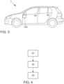
- Fig. 3 is a roughly schematic representation of a motor vehicle 1 with a Fig. 1 shown component assembly 100, wherein the component assembly 100 is arranged in an instrument panel area of the motor vehicle 1 or as a component of an instrument panel of the motor vehicle 1.
- FIG. 4 A method for producing a component assembly 100 according to the invention for an instrument panel or a motor vehicle 1 with this instrument panel is then described.
- a plastic base body 10 for an instrument panel and a plastic functional component 20 in the form of an airbag firing channel are provided in a first step S1.
- Polypropylene or a filled polypropylene or a fiber-reinforced polypropylene or a polypropylene derivative is preferably used as the plastic material.
- the functional component 20 is injection molded onto the base body 10 during the production of the component assembly 100, wherein the component assembly 100 is produced using an external gas pressure process.
- external gas pressure is applied to a flat region 11 of the base body 10 around the at least one functional component 20, wherein the flat region 11 is arranged on the rear side of the base body 10 facing away from the visible side of the base body 10.
- the functional component 20 is cooled in sections with a CO2 point cooling, which is applied by a mold for producing the component composite 100. More precisely, in this step, several pockets or recessed sections 21 of a stiffening structure of the functional component 20 are specifically cooled with a CO2 point cooling, which is applied by the mold for producing the component composite 100.
Landscapes
- Engineering & Computer Science (AREA)
- Mechanical Engineering (AREA)
- Manufacturing & Machinery (AREA)
- Air Bags (AREA)
- Instrument Panels (AREA)
- Compositions Of Macromolecular Compounds (AREA)
- Injection Moulding Of Plastics Or The Like (AREA)
Description
- Die vorliegende Erfindung betrifft ein Verfahren zum Herstellen eines Bauteilverbundes für ein Kraftfahrzeug, wobei der Bauteilverbund einen Grundkörper für eine Instrumententafel des Kraftfahrzeugs aufweist. Die vorliegende Erfindung betrifft ferner einen Bauteilverbund für ein Kraftfahrzeug sowie ein Kraftfahrzeug.
- Im Stand der Technik ist es bekannt, komplexe Bauteile für ein Kraftfahrzeug aus verschiedenen Einzelkomponenten bzw. Bauteilstrukturen zusammen zu stellen und anschließend zusammen zu bauen. Dies führt zu entsprechend hohen Kosten, da nicht nur ein erhöhter Zeitaufwand zum Fügen der verschiedenen Bauteilstrukturen erforderlich ist, sondern auch die verschiedenen Bauteilstrukturen jeweils hergestellt, transportiert und gelagert werden müssen.
- Bei einem Bauteilverbund, der aus einer Vielzahl von verschiedenen Bauteilstrukturen besteht, ist außerdem eine Vielzahl von verschiedenen Verbindungselementen erforderlich, die zum Verbinden der jeweiligen Bauteilstrukturen verwendet werden. Dies führt zu dem Problem, dass ein entsprechend ausgestalteter Bauteilverbund ein relativ hohes Gewicht aufweist. Das Gewicht gilt es jedoch im Fahrzeugbau zu minimieren.
- Für eine Gewichtsreduzierung kann die Wandstärke einer Bauteilstruktur oder eines Bauteilverbundes verringert werden. Dies führt jedoch auch zu einer entsprechend verringerten Steifigkeit und/oder verringerten Festigkeit. Außerdem kann die Wandstärke mit üblichen Herstellungsverfahren nur bis zu einem gewissen Grad reduziert werden. Neben einer minimal erforderlichen Steifigkeit an bestimmten Stellen der Bauteilstruktur ist auch eine gewünschte Oberflächengüte eine Bedingung, aufgrund welcher die Wandstärke von bestimmten Bauteilstrukturen nicht beliebig reduziert werden kann oder darf.
- Aus der deutschen Patentanmeldung
DE 10 2010 031 814 A1 ist es bekannt, Kunststoffteile wie zum Beispiel Zier- und Verblendungsteile im Automobilbereich für Instrumententafeln, Türverkleidungen und Säulenverkleidungen mittels eines Gasaußendruckverfahrens herzustellen. Der Anwendungsbereich des Gasaußendruckverfahrens ist dabei auf kleine Bauteilstrukturen beschränkt. - Die
DE 10 2005 038 469 A1 beschreibt ein Verfahren zum Herstellen eines Spritzguss-Kunststoffbauteils und ein entsprechend hergestelltes Kunststoffbauteil. DieDE 601 06 348 T2 offenbart ein Spritzgießverfahren. In derDE 10 2006 058 546 A1 ist eine Airbagklappe für einen Beifahrersitz und ein Verfahren zur Herstellung derselben gezeigt. - Ein weiteres Verfahren zum Herstellen eines Spritzguss-Kunststoffbauteils ist aus der
FR 2 873 613 A1 US 2005/0121818 A1 bekannt. - Aufgabe der vorliegenden Erfindung ist es, der voranstehend beschriebenen Problematik zumindest teilweise Rechnung zu tragen. Insbesondere ist es Aufgabe der vorliegenden Erfindung, ein verbessertes Verfahren zum Herstellen eines Bauteilverbundes für ein Kraftfahrzeug, einen verbesserten Bauteilverbund für ein Kraftfahrzeug sowie ein Kraftfahrzeug mit einem entsprechend verbesserten Bauteilverbund zur Verfügung zu stellen.
- Die voranstehende Aufgabe wird durch die Gegenstände der Patentansprüche gelöst. Insbesondere wird die voranstehende Aufgabe durch das Verfahren gemäß Anspruch 1, den Bauteilverbund gemäß Anspruch 7 sowie das Kraftfahrzeug gemäß Anspruch 9 gelöst. Weitere Merkmale und Details der Erfindung ergeben sich aus den Unteransprüchen, der Beschreibung und den Zeichnungen. Dabei gelten Merkmale, die im Zusammenhang mit dem erfindungsgemäßen Verfahren beschrieben sind, selbstverständlich auch im Zusammenhang mit dem erfindungsgemäßen Bauteilverbund, dem erfindungsgemäßen Kraftfahrzeug und jeweils umgekehrt, sodass bezüglich der Offenbarung zu den einzelnen Erfindungsaspekten stets wechselseitig Bezug genommen wird bzw. werden kann.
- Gemäß eines ersten Aspekts der vorliegenden Erfindung wird ein Verfahren zum Herstellen eines Bauteilverbundes für ein Kraftfahrzeug zur Verfügung gestellt, wobei der Bauteilverbund einen Grundkörper für eine Instrumententafel des Kraftfahrzeugs sowie wenigstens ein Funktionsbauteil aufweist. Bei dem Verfahren wird das wenigstens eine Funktionsbauteil bei bzw. während der Herstellung des Bauteilverbundes an den Grundkörper angespritzt, wobei der Bauteilverbund unter Verwendung eines Gasaußendruckverfahrens hergestellt wird.
- Durch das Anwenden eines Gasaußendruckverfahrens während des Anspritzens des wenigstens einen Funktionsbauteils an den Grundkörper ist es möglich, Einfallstellen im Bereich des angespritzten Funktionsbauteils am Grundkörper zu verringern oder sogar vollständig zu vermeiden, und dennoch einen Bauteilverbund mit einer besonders komplexen und großflächigen Bauteilstruktur zu erzeugen. Einfallstellen können durch das vorliegende Verfahren verhindert oder zumindest derart reduziert werden, dass es zu keiner für einen Endkunden optisch nachteiligen Beeinträchtigung am Grundkörper bzw. am Strukturbauteil kommt.
- Das wenigstens eine Funktionsbauteil ist dabei bevorzugt ein grundkörperunspezifisches Funktionsbauteil, das grundsätzlich nicht elementarer Bestandteil des Grundkörpers der Instrumententafel ist und auch separat vom Grundkörper im Kraftfahrzeug angeordnet werden könnte. Unter dem Grundkörper ist dabei grundsätzlich eine Instrumententafel-Grundstruktur zu verstehen, die zur Ausbildung oder Mitausbildung eines Instrumententafelbereichs des Kraftfahrzeugs sowie zur Aufnahme von Bedienelementen für einen Fahrzeuginsassen des Kraftfahrzeugs ausgestaltet und anordenbar ist. Unter dem Funktionsbauteil ist beispielsweise nicht eine bloße Durchgangsöffnung im Grundkörper zu verstehen, welche ein Anzeige- oder Bedienelement für einen Fahrzeuginsassen aufnehmen kann. Vielmehr ist unter dem wenigstens einen Funktionsbauteil ein Funktionsbauteil zu verstehen, das für eine erhebliche mechanische Wechselwirkung mit einem anderen Funktionsbauteil im Kraftfahrzeug zusammen wirkt oder zumindest dafür ausgestaltet sein kann. Das Funktionsbauteil kann beispielsweise ein Volumen aufweisen oder "aufspannen", das größer als 0,1 dm3 ist, beispielsweise zwischen 0,1 dm3 und 100 dm3, bevorzugt zwischen 0,5 dm3 und 50 dm3.
- Der Gasaußendruck muss bei der Herstellung bzw. beim Spritzgießen des Bauteilverbundes nicht auf die gesamte Fläche des Bauteilverbundes aufgebracht werden. Vielmehr wird bei der Herstellung des Bauteilverbundes der Gasaußendruck gezielt zumindest in einem Bereich aufgebracht, in welchem das wenigstens eine Funktionsbauteil bei der Herstellung des Bauteilverbundes an den Grundkörper angespritzt wird. Dadurch kann etwaigen späteren Einfallstellen am Bauteilverbund gezielt entgegengewirkt werden.
- Unter einem Bauteilverbund ist vorliegend ein Verbund von grundsätzlich zwei unterschiedlichen und/oder separaten Bauteilen zu verstehen, die für eine Platzersparnis sowie eine gezielte positive Wechselwirkung durch den Bauteilverbund miteinander verbunden werden. Das Herstellen des Bauteilverbundes ist dabei nicht darauf beschränkt, dass das wenigstens eine Funktionsbauteil erst nach Fertigstellung des Grundkörpers an diesem angespritzt wird. Vielmehr ist es vorliegend bevorzugt, dass das wenigstens eine Funktionsbauteil unmittelbar bei der Herstellung des Bauteilverbundes in den Grundkörper integriert bzw. an diesen angespritzt wird.
- Das Kraftfahrzeug ist vorliegend nicht auf ein Straßenfahrzeug oder einen Personenkraftwagen beschränkt. So kann das erfindungsgemäße Verfahren auch zum Herstellen eines Bauteilverbundes für einen Lastkraftwagen, ein Wasserfahrzeug, ein Schienenfahrzeug, ein Luftfahrzeug und/oder einen Roboter zur Verfügung gestellt werden.
- Gemäß der vorliegenden Erfindung weist bei dem Verfahren das wenigstens eine Funktionsbauteil einen Airbag-Schusskanal auf oder ist als solcher ausgestaltet. D.h., der Airbag-Schusskanal wird bei der Herstellung des Bauteilverbundes unter Verwendung eines Gasaußendruckverfahrens an den Grundkörper für die Instrumententafel angespritzt. Da es bei einem Anspritzen des Airbag-Schusskanals bisher zu enormen Oberflächen-Beeinträchtigungen bzw. Einfallstellen sowie Verspannungen in einem Grundkörper kam, welche einen entsprechenden Bauteilverbund auch noch nachträglich negativ beeinflussen konnten, wurde bisher von einem Anspritzen des Airbag-Schusskanals an einen Grundkörper für eine spritzblanke Instrumententafel Abstand genommen. Deshalb war es bisher üblich, für eine spritzblanke Instrumententafel einen Airbag-Schusskanal als Zusatzteil an einen Grundkörper für die Instrumententafel zu schweißen und anschließend eine Oberfläche der Instrumententafel zu kaschieren, beispielsweise mit einer sogenannten Slush-Haut. Dies ist jedoch zeitaufwändig und entsprechend teuer. Im Rahmen der vorliegenden Erfindung wurde nun herausgefunden, dass das Gasaußendruckverfahren auch bei großflächigen Strukturbauteilen wie dem Grundkörper für eine Instrumententafel anwendbar ist und sich darüber hinaus der Airbag-Schusskanal bei Anwendung dieses Verfahrens besonders vorteilhaft an den Grundkörper anspritzen lässt. Der daraus resultierende Bauteilverbund kann hierbei entsprechend schnell und kostengünstig hergestellt werden. Außerdem kommt beim Anspritzen des Airbag-Schusskanals an den Grundkörper bei Verwendung des Gasaußendruckverfahrens besonders wenig oder kein Zusatzmaterial zum Einsatz, wodurch der Bauteilverbund gewichtssparend bereitgestellt werden kann. Der vorliegende Airbag-Schusskanal dient zur Führung eines Gassackes des Airbags, insbesondere eines Beifahrerairbags, bei der Entfaltung desselben.
- Es ist vorteilhaft, wenn das wenigstens eine Funktionsbauteil, insbesondere der Airbag-Schusskanal, an eine einer Sichtseite des Grundkörpers abgewandte Rückseite des Grundkörpers angespritzt wird. Durch die Verwendung des Gasaußendruckverfahrens wird Oberflächen-Beeinträchtigungen bzw. Einfallstellen sowie Verspannungen auf der Sichtseite des Grundkörpers, die sonst beim Anspritzen des Funktionsbauteils an die Rückseite des Grundkörpers auftreten können, wirksam entgegengewirkt, so dass die Sichtseite des Grundkörpers der Instrumententafel zumindest im Wesentlichen unbeeinflusst bleibt. Unter der Sichtseite des Grundkörpers der Instrumententafel wird dabei diejenige Seite des Grundkörpers der Instrumententafel verstanden, die im ins Fahrzeug eingebauten Zustand der Instrumententafel zumindest im Wesentlichen dem Fahrzeuginnenraum des Fahrzeugs zugewandt ist.
- Ferner ist es im Rahmen der vorliegenden Erfindung vorgesehen, dass beim Herstellen des Bauteilverbundes Gasaußendruck auf einen flächigen Bereich des Grundkörpers um das wenigstens eine Funktionsbauteil herum aufgebracht wird. Bevorzugt ist der flächige Bereich des Grundkörpers aus den bereits geschilderten Gründen auf einer einer Sichtseite des Grundkörpers abgewandten Rückseite des Grundkörpers angeordnet. Hierdurch kann ein großer Teil einer Volumenschwindung während eines Erstarrungsprozesses kompensiert und als Ursache für Einfallstellen an der Oberfläche des Grundkörpers ausgeschlossen oder zumindest stark reduziert werden. Unter einem flächigen Bereich ist ein Bereich von beispielsweise mehr als 50 cm2, insbesondere zwischen 50 cm2 und 1000 cm2, bevorzugt zwischen 100 cm2 und 500 cm2 zu verstehen, in welchem kein Vorsprung oder dergleichen ausgestaltet ist bzw. welcher sich homogen oder im Wesentlichen homogen und dabei bevorzugt eben erstreckt.
- Außerdem kann es gemäß der vorliegenden Erfindung von Vorteil sein, wenn bei dem Herstellen des Bauteilverbundes das wenigstens eine Funktionsbauteil zumindest abschnittsweise mit einer CO2-Punktkühlung, die insbesondere durch ein Formwerkzeug zum Herstellen des Bauteilverbundes aufgebracht wird, gekühlt wird. Dabei wird in eine werkzeugseitige Kontur des Formwerkzeugs, die komplementär zu einem zugehörigen Abschnitt des Bauteilverbundes bzw. des Grundkörpers und/oder des Funktionsbauteils ausgestaltet ist, eine CO2-Kühlung bzw. eine CO2-Punktkühlung eingebracht, um ein erhöhtes Aufheizen von Konturbereichen im Formwerkzeug zu vermeiden. Dadurch werden Hot-Spots im Produkt vermieden, welche für die bereits vorstehend erwähnten Einfallstellen mitverantwortlich sind.
- Von weiterem Vorteil kann es bei einem erfindungsgemäßen Verfahren sein, wenn bei dem Herstellen des Bauteilverbundes wenigstens ein Vertiefungsabschnitt des wenigstens einen Funktionsbauteils mit einer CO2-Punktkühlung, die insbesondere durch ein Formwerkzeug zum Herstellen des Bauteilverbundes aufgebracht wird, gezielt gekühlt wird. Der wenigstens eine Vertiefungsabschnitt wird dabei bevorzugt durch einen komplementär ausgestalteten Vorsprungsabschnitt des Formwerkzeugs gekühlt, wobei die CO2-Punktkühlung durch den wenigstens einen Vorsprungsabschnitt jeweils zumindest teilweise in den zugehörigen bzw. komplementären Vertiefungsabschnitt eingebracht wird. Durch die gezielte CO2-Punktkühlung des Funktionsbauteils auch in dem wenigstens einen Vertiefungsabschnitt, d.h., in einem inneren Bereich des Funktionsbauteils, ist es möglich, etwaige Einfallstellen besonders zuverlässig zu verringern oder sogar zu verhindern. Der wenigstens eine Vertiefungsabschnitt kann beispielsweise als wenigstens ein Vertiefungsabschnitt oder als eine Vielzahl von Vertiefungsabschnitten einer Versteifungsstruktur eines Airbag-Schusskanals ausgestaltet sein. Der wenigstens eine Vertiefungsabschnitt des Funktionsbauteils ist dabei bevorzugt als wenigstens ein Taschenabschnitt des Funktionsbauteils ausgestaltet.
- Darüber hinaus ist es gemäß der vorliegenden Erfindung möglich, dass der Bauteilverbund unter Verwendung des Gasaußendruckverfahrens sowie unter Verwendung von Polypropylen (PP) hergestellt wird. Dabei wird insbesondere der Grundkörper unter Verwendung von Polypropylen hergestellt. Durch die Verwendung von Polypropylen kann der Bauteilverbund bzw. der Grundkörper mit besonders vorteilhaften Material- und entsprechenden Oberflächeneigenschaften bereitgestellt werden. Der Bauteilverbund wird dabei derart hergestellt, dass dieser nach seiner Herstellung überwiegend Polypropylen aufweist oder im Wesentlichen, vollständig oder zumindest im Wesentlichen vollständig aus Polypropylen besteht. Durch das verwendete Polypropylen kann der Bauteilverbund oder zumindest eine Oberfläche des Grundkörpers, die bei der Verwendung in einem Kraftfahrzeug in Richtung einer Fahrzeugkabine angeordnet ist, in Kombination mit dem Gasaußendruckverfahren spritzblank oder genarbt hergestellt werden. Unter einer spritzblanken oder genarbten Herstellung ist eine Herstellung des Bauteilverbundes mit einer zumindest abschnittsweise definierten Oberflächengüte oder -struktur nach dem Spritzgießen zu verstehen. D.h., wenn der Bauteilverbund beispielsweise spritzblank hergestellt wird, weist eine Oberfläche des Bauteilverbundes nach dem Spritzgießen eine definierte Oberflächengüte auf. Die gewünschte Oberflächengüte kann dabei insbesondere durch das Gasaußendruckverfahren während des Spritzgießens erreicht werden. Durch das angewandte Gasaußendruckverfahren kombiniert mit dem verwendeten Polypropylen weist der Bauteilverbund keine oder keine wesentlichen sichtbaren Einfallstellen und eine entsprechend spritzblanke Oberfläche auf. D.h., bereits direkt nach dem Spritzgießen ist die Oberfläche des Bauteilverbundes bzw. des Grundkörpers "blank" bzw. wie gewünscht genarbt.
- Gemäß eines weiteren Aspekts der vorliegenden Erfindung wird ein Bauteilverbund für ein Kraftfahrzeug bereitgestellt, wobei der Bauteilverbund gemäß eines wie vorstehend im Detail beschriebenen Verfahrens hergestellt ist. Damit bringt der erfindungsgemäße Bauteilverbund die gleichen Vorteile mit sich, wie sie ausführlich mit Bezug auf das erfindungsgemäße Verfahren beschrieben worden sind.
- Im Rahmen der vorliegenden Erfindung wird ferner der Bauteilverbund für ein Kraftfahrzeug bereitgestellt, wobei der Bauteilverbund einen Grundkörper für eine Instrumententafel sowie wenigstens ein Funktionsbauteil aufweist und der Grundkörper zusammen mit dem wenigstens einen Funktionsbauteil als integrales Kunststoff-Spritzgussteil unter Verwendung eines Gasaußendruckverfahrens hergestellt ist. Durch die integrale Herstellung bzw. den entsprechend integralen Aufbau des Bauteilverbundes kann dieser besonders leicht und dennoch stabil bereitgestellt werden. Unter einem integralen Spritzgussteil ist vorliegend ein einstückiges oder monolithisches Spritzgussbauteil zu verstehen.
- Das wenigstens eine Funktionsbauteil ist gemäß der vorliegenden Erfindung bevorzugt als ein Airbag-Schusskanal, insbesondere als ein Beifahrerairbag-Schusskanal, bereitgestellt. Demnach sind der Grundkörper und der Airbag-Schusskanal als einstückiges oder monolithisches Spritzgussbauteil bzw. als ein entsprechender Bauteilverbund bereitgestellt, der keine Schweißnaht oder ein anderes stoff-, form- und/oder kraftschlüssiges zusätzliches Verbindungselement aufweist bzw. benötigt.
- Gemäß eines weiteren Aspekts der vorliegenden Erfindung wird ein Kraftfahrzeug mit einem wie vorstehend beschriebenen Bauteilverbund zur Verfügung gestellt. Damit bringt auch das erfindungsgemäße Kraftfahrzeug die gleichen Vorteile mit sich, wie sie ausführlich mit Bezug auf das erfindungsgemäße Verfahren beschrieben worden sind.
- Weitere, die Erfindung verbessernde Maßnahmen ergeben sich aus der nachfolgenden Beschreibung zu verschiedenen Ausführungsbeispielen der Erfindung, welche in den Figuren schematisch dargestellt sind. Sämtliche aus den Ansprüchen, der Beschreibung oder der Zeichnung hervorgehende Merkmale und/oder Vorteile, einschließlich konstruktiver Einzelheiten und räumlicher Anordnungen, können sowohl für sich als auch in den verschiedenen Kombinationen erfindungswesentlich sein. Es zeigen jeweils schematisch:
-
Fig. 1 einen Bauteilverbund gemäß einer Ausführungsform der vorliegenden Erfindung, -
Fig. 2 einen Ausschnitt eines Bauteilverbundes gemäß der inFig. 1 dargestellten Ausführungsform der vorliegenden Erfindung, -
Fig. 3 ein Kraftfahrzeug mit dem inFig. 1 dargestellten Bauteilverbund, und -
Fig. 4 ein Ablaufdiagramm zum Erläutern eines erfindungsgemäßen Verfahrens zum Herstellen eines Bauteilverbunds. - Elemente mit gleicher Funktion und Wirkungsweise sind in den
Figuren 1 bis 4 jeweils mit denselben Bezugszeichen versehen. -
Fig. 1 zeigt einen Bauteilverbund 100 für ein Kraftfahrzeug 1 gemäß einer bevorzugten Ausführungsform der vorliegenden Erfindung. Der Bauteilverbund 100 gemäßFig. 1 weist einen im Wesentlichen aus Polypropylen bestehenden Grundkörper 10 für eine Instrumententafel des Kraftfahrzeugs 1 sowie ein Funktionsbauteil 20 auf, wobei das Funktionsbauteil 20 als Airbag-Schusskanal an einer Hinterseite des Grundkörpers 10, die eine einer Sichtseite des Grundkörpers 10 abgewandte Rückseite des Grundkörpers 10 darstellt, ausgestaltet ist. Die Hinterseite oder Rückseite des Grundkörpers 10 entspricht dabei einer Seite des Grundkörpers 10 für die Instrumententafel, die in Richtung oder im Wesentlichen in Richtung einer Vorderseite des Kraftfahrzeugs 1 zeigt, wenn der Bauteilverbund 100 im Kraftfahrzeug 1 verbaut ist, und somit im verbauten Zustand des Bauteilverbunds 100 dem Fahrzeuginnenraum des Kraftfahrzeugs 1 abgewandt ist. Entsprechend ist unter einer Vorderseite des Grundkörpers 10 für die Instrumententafel eine Sichtseite zu verstehen, die in Richtung oder im Wesentlichen in Richtung eines Fahrzeuginnenraums des Kraftfahrzeugs 1 zeigt, wenn der Bauteilverbund 100 im Kraftfahrzeug 1 verbaut ist. - Der Grundkörper 10 ist gemäß
Fig. 1 zusammen mit dem als Airbag-Schusskanal ausgestalteten Funktionsbauteil 20 unter Verwendung eines Gasaußendruckverfahrens als integrales bzw. einstückiges Kunststoff-Spritzgussteil hergestellt. Der Airbag-Schusskanal 20 aus Kunststoff ist dabei als Airbag-Schusskanal für einen Beifahrerairbag bzw. als Beifahrerairbag-Schusskanal ausgestaltet und an einer entsprechend geeigneten Position am Grundkörper 10 für die Instrumententafel, nämlich an der Hinterseite bzw. Rückseite des Grundkörpers 10, angeordnet. -
Fig. 2 zeigt eine vergrößerte Darstellung der Anordnung des als Airbag-Schusskanal ausgestalteten Funktionsbauteils 20 am Grundkörper 10. InFig. 2 ist dabei ein flächiger Bereich 11 des Grundkörpers 10 dargestellt, der um den Airbag-Schusskanal 20 herum ausgestaltet ist und über welchen bei der Herstellung des Bauteilverbundes 100 ein Gasaußendruck aufgebracht wird. Der flächige Bereich 11 ist an der Hinterseite bzw. Rückseite des Grundkörpers 10 angeordnet. InFig. 2 sind außerdem mehrere Vertiefungen 21 einer Versteifungsstruktur des Airbag-Schusskanals 20 dargestellt. - In
Fig. 3 ist grob schematisch ein Kraftfahrzeug 1 mit einem gemäßFig. 1 dargestellten Bauteilverbund 100 gezeigt, wobei der Bauteilverbund 100 in einem Instrumententafelbereich des Kraftfahrzeugs 1 bzw. als Bestandteil einer Instrumententafel des Kraftfahrzeugs 1 angeordnet ist. - Mit Bezug auf
Fig. 4 wird anschließend ein Verfahren zum Herstellen eines erfindungsgemäßen Bauteilverbundes 100 für eine Instrumententafel bzw. ein Kraftfahrzeug 1 mit dieser Instrumententafel beschrieben. - Zur Herstellung des Bauteilverbundes 100 werden in einem ersten Schritt S1 ein Kunststoff-Grundkörper 10 für eine Instrumententafel sowie ein Kunststoff-Funktionsbauteil 20 in Form eines Airbag-Schusskanals bereitgestellt. Als Kunststoffmaterial wird bevorzugt Polypropylen oder ein gefülltes Polypropylen oder ein faserverstärktes Polypropylen oder ein Polypropylen-Derivat verwendet.
- In einem zweiten, anschließenden oder zumindest teilweise parallel ablaufenden Schritt S2 wird das Funktionsbauteil 20 bei der Herstellung des Bauteilverbundes 100 an den Grundkörper 10 angespritzt, wobei der Bauteilverbund 100 unter Verwendung eines Gasaußendruckverfahrens hergestellt wird. Hierbei wird Gasaußendruck auf einen flächigen Bereich 11 des Grundkörpers 10 um das wenigstens eine Funktionsbauteil 20 herum aufgebracht, wobei der flächige Bereich 11 an der der Sichtseite des Grundkörpers 10 abgewandten Rückseite des Grundkörpers 10 angeordnet ist.
- In einem dritten Schritt, der während der Herstellung des Bauteilverbundes 100 durchgeführt wird, wird das Funktionsbauteil 20 abschnittsweise mit einer CO2-Punktkühlung, die durch ein Formwerkzeug zum Herstellen des Bauteilverbundes 100 aufgebracht wird, gekühlt. Genauer gesagt werden bei diesem Schritt mehrere Taschen bzw. Vertiefungsabschnitte 21 einer Versteifungsstruktur des Funktionsbauteils 20 mit einer CO2-Punktkühlung, die durch das Formwerkzeug zum Herstellen des Bauteilverbundes 100 aufgebracht wird, gezielt gekühlt.
- Neben den beschriebenen Ausführungsformen lässt die vorliegende Erfindung noch weitere Ausgestaltungen zu.
-
- 1
- Kraftfahrzeug
- 10
- Grundkörper
- 11
- flächiger Bereich
- 20
- Funktionsbauteil, insbesondere Airbag-Schusskanal
- 21
- Vertiefungsabschnitt
- 100
- Bauteilverbund
Claims (9)
- Verfahren zum Herstellen eines Bauteilverbundes (100) für ein Kraftfahrzeug (1), wobeider Bauteilverbund (100) einen Grundkörper (10) für eine Instrumententafel des Kraftfahrzeugs (1) sowie wenigstens ein Funktionsbauteil (20) aufweist, wobei das wenigstens eine Funktionsbauteil (20) einen Airbag-Schusskanal aufweist oder als solcher ausgestaltet ist, dadurch gekennzeichnet, dass daswenigstens eine Funktionsbauteil (20) bei der Herstellung des Bauteilverbundes (100) an den Grundkörper (10) angespritzt wird und der Bauteilverbund (100) unter Verwendung eines Gasaußendruckverfahrens hergestellt wird,wobei beim Herstellen des Bauteilverbundes (100) Gasaußendruck auf einen flächigen Bereich (11) des Grundkörpers (10) um das wenigstens eine Funktionsbauteil (20) herum aufgebracht wird.
- Verfahren nach dem voranstehenden Anspruch,
dadurch gekennzeichnet,
dass das wenigstens eine Funktionsbauteil (20) an eine einer Sichtseite des Grundkörpers (10) abgewandte Rückseite des Grundkörpers (10) angespritzt wird. - Verfahren nach einem der voranstehenden Ansprüche,
dadurch gekennzeichnet,
dass der flächige Bereich (11) des Grundkörpers (10) auf einer einer Sichtseite des Grundkörpers (10) abgewandten Rückseite des Grundkörpers (10) angeordnet ist. - Verfahren nach einem der voranstehenden Ansprüche,
dadurch gekennzeichnet,
dass bei dem Herstellen des Bauteilverbundes (100) das wenigstens eine Funktionsbauteil (20) zumindest abschnittsweise mit einer CO2-Punktkühlung, die insbesondere durch ein Formwerkzeug zum Herstellen des Bauteilverbundes (100) aufgebracht wird, gekühlt wird. - Verfahren nach einem der voranstehenden Ansprüche,
dadurch gekennzeichnet,
dass bei dem Herstellen des Bauteilverbundes (100) wenigstens ein Vertiefungsabschnitt (21) des wenigstens einen Funktionsbauteils (20) mit einer CO2-Punktkühlung, die insbesondere durch ein Formwerkzeug zum Herstellen des Bauteilverbundes (100) aufgebracht wird, gekühlt wird. - Verfahren nach einem der voranstehenden Ansprüche,
dadurch gekennzeichnet,
dass der Bauteilverbund (100) unter Verwendung des Gasaußendruckverfahrens sowie unter Verwendung von Polypropylen hergestellt wird. - Bauteilverbund (100) für ein Kraftfahrzeug (1), aufweisend einen Grundkörper (10) für eine Instrumententafel des Kraftfahrzeugs (1) sowie wenigstens ein Funktionsbauteil (20), dadurch gekennzeichnet,dass der Grundkörper (10) zusammen mit dem wenigstens einen Funktionsbauteil (20) unter Verwendung eines Gasaußendruckverfahrens als integrales Spritzgussteil hergestellt ist, wobei das wenigstens eine Funktionsbauteil (20) einen Airbag-Schusskanal aufweist oder ein Airbag-Schusskanal ist,wobei der Bauteilverbund (100) gemäß eines Verfahrens nach einem der voranstehenden Ansprüche hergestellt ist.
- Bauteilverbund nach Anspruch 7,
dadurch gekennzeichnet,
dass das wenigstens eine Funktionsbauteil (20) an eine einer Sichtseite des Grundkörpers (10) abgewandte Rückseite des Grundkörpers (10) angespritzt ist. - Kraftfahrzeug (1) mit einem Bauteilverbund (100) nach Anspruch 7 oder 8.
Applications Claiming Priority (2)
| Application Number | Priority Date | Filing Date | Title |
|---|---|---|---|
| DE102016213963.0A DE102016213963A1 (de) | 2016-07-28 | 2016-07-28 | Verfahren zum Herstellen eines Bauteilverbundes für ein Kraftfahrzeug, Bauteilverbund für ein Kraftfahrzeug sowie Kraftfahrzeug mit dem Bauteilverbund |
| PCT/EP2017/065407 WO2018019493A1 (de) | 2016-07-28 | 2017-06-22 | Verfahren zum herstellen eines bauteilverbundes für ein kraftfahrzeug, bauteilverbund für ein kraftfahrzeug sowie kraftfahrzeug mit dem bauteilverbund |
Publications (2)
| Publication Number | Publication Date |
|---|---|
| EP3490768A1 EP3490768A1 (de) | 2019-06-05 |
| EP3490768B1 true EP3490768B1 (de) | 2025-02-19 |
Family
ID=59270002
Family Applications (1)
| Application Number | Title | Priority Date | Filing Date |
|---|---|---|---|
| EP17734682.2A Active EP3490768B1 (de) | 2016-07-28 | 2017-06-22 | Verfahren zum herstellen eines bauteilverbundes für ein kraftfahrzeug, bauteilverbund für ein kraftfahrzeug sowie kraftfahrzeug mit dem bauteilverbund |
Country Status (5)
| Country | Link |
|---|---|
| US (1) | US10596738B2 (de) |
| EP (1) | EP3490768B1 (de) |
| CN (1) | CN109476047B (de) |
| DE (1) | DE102016213963A1 (de) |
| WO (1) | WO2018019493A1 (de) |
Families Citing this family (2)
| Publication number | Priority date | Publication date | Assignee | Title |
|---|---|---|---|---|
| DE102017213453A1 (de) | 2017-08-03 | 2019-02-07 | Volkswagen Aktiengesellschaft | Verfahren und Vorrichtung zum Herstellen eines Verkleidungsteils eines Kraftfahrzeugs, Verwendung der Vorrichtung |
| DE102022213000A1 (de) | 2022-12-02 | 2024-06-13 | Volkswagen Aktiengesellschaft | Verfahren zur Herstellung einer Instrumententafel für ein Fahrzeug |
Citations (4)
| Publication number | Priority date | Publication date | Assignee | Title |
|---|---|---|---|---|
| US20050121818A1 (en) * | 2003-12-09 | 2005-06-09 | Cowelchuk Glenn A. | Method of manufacturing an airbag assembly and vehicle trim component |
| FR2873613A1 (fr) * | 2004-11-25 | 2006-02-03 | Faurecia Interieur Ind Snc | Procede de realisation d'une piece d'equipement interieur de vehicule automobile et moule de realisation associe |
| DE102005038469A1 (de) * | 2005-08-13 | 2007-02-15 | Daimlerchrysler Ag | Verfahren zum Herstellen eines Spritzguss-Kunststoffbauteils und entsprechend hergestelltes Kunststoffbauteil |
| US20080111281A1 (en) * | 2006-11-14 | 2008-05-15 | Autoliv Asp, Inc. | Gas assisted injection molding method |
Family Cites Families (17)
| Publication number | Priority date | Publication date | Assignee | Title |
|---|---|---|---|---|
| AU635235B2 (en) | 1988-12-05 | 1993-03-18 | Robert E. Carroll | Injection mold method and apparatus |
| US5162092A (en) * | 1990-11-29 | 1992-11-10 | Cascade Engineering, Inc. | Gas-assisted injection molding with a carpet layer |
| US5456957A (en) * | 1992-03-06 | 1995-10-10 | The Standard Products Company | Body side molding and method |
| US5716560A (en) * | 1995-09-14 | 1998-02-10 | Icp Systems, Inc. | Gas assisted injection molding combining internal and external gas pressures |
| DE19746827C2 (de) | 1997-10-23 | 2001-08-16 | Battenfeld Gmbh | Verfahren zum Spritzgießen von Kunststoffgegenständen mittels Druckfluid |
| US6432350B1 (en) * | 2000-06-14 | 2002-08-13 | Incoe Corporation | Fluid compression of injection molded plastic materials |
| JP3445778B2 (ja) | 2000-08-11 | 2003-09-08 | 東北ムネカタ株式会社 | 射出成形方法 |
| JP3840897B2 (ja) | 2000-12-26 | 2006-11-01 | 豊田合成株式会社 | エアバッグカバー部付き自動車内装品 |
| DE10160192A1 (de) | 2001-12-07 | 2003-06-26 | Trw Repa Gmbh | Instrumententafel mit Aufnahme für ein Gassack-Modul |
| US7182904B2 (en) * | 2003-12-23 | 2007-02-27 | Lear Corporation | Low pressure laminate gas assist molding |
| KR100828817B1 (ko) * | 2006-10-31 | 2008-05-09 | 현대자동차주식회사 | 승객용 에어백 도어 및 그 제조 방법 |
| DE102010031814A1 (de) | 2010-07-21 | 2011-05-12 | Daimler Ag | Formwerkzeug, Verfahren zu dessen Herstellung und Verfahren zur Herstellung eines Formteils |
| EP2607043A1 (de) * | 2011-12-20 | 2013-06-26 | Linde Aktiengesellschaft | Kühlung eines durch Gasinjektionstechnik geformten Gaskanals mit flüssigem Kohlendioxid |
| US10369953B2 (en) * | 2015-04-24 | 2019-08-06 | Faurecia Interior Systems, Inc. | Interior panels including substrates with inserts for defining integrated airbag deployment doors for motor vehicles and methods of making the same |
| JP6451551B2 (ja) * | 2015-08-21 | 2019-01-16 | 豊田合成株式会社 | 自動車用エアバッグドア |
| JP2017052401A (ja) * | 2015-09-09 | 2017-03-16 | 豊田合成株式会社 | 自動車用エアバッグドア |
| CN107498774A (zh) * | 2016-06-14 | 2017-12-22 | 福特环球技术公司 | 用于制造带有削弱部分注塑件的系统和方法 |
-
2016
- 2016-07-28 DE DE102016213963.0A patent/DE102016213963A1/de not_active Withdrawn
-
2017
- 2017-06-22 WO PCT/EP2017/065407 patent/WO2018019493A1/de not_active Ceased
- 2017-06-22 CN CN201780046450.6A patent/CN109476047B/zh active Active
- 2017-06-22 EP EP17734682.2A patent/EP3490768B1/de active Active
-
2019
- 2019-01-28 US US16/259,495 patent/US10596738B2/en active Active
Patent Citations (4)
| Publication number | Priority date | Publication date | Assignee | Title |
|---|---|---|---|---|
| US20050121818A1 (en) * | 2003-12-09 | 2005-06-09 | Cowelchuk Glenn A. | Method of manufacturing an airbag assembly and vehicle trim component |
| FR2873613A1 (fr) * | 2004-11-25 | 2006-02-03 | Faurecia Interieur Ind Snc | Procede de realisation d'une piece d'equipement interieur de vehicule automobile et moule de realisation associe |
| DE102005038469A1 (de) * | 2005-08-13 | 2007-02-15 | Daimlerchrysler Ag | Verfahren zum Herstellen eines Spritzguss-Kunststoffbauteils und entsprechend hergestelltes Kunststoffbauteil |
| US20080111281A1 (en) * | 2006-11-14 | 2008-05-15 | Autoliv Asp, Inc. | Gas assisted injection molding method |
Also Published As
| Publication number | Publication date |
|---|---|
| US10596738B2 (en) | 2020-03-24 |
| CN109476047B (zh) | 2022-03-08 |
| DE102016213963A1 (de) | 2018-02-01 |
| WO2018019493A1 (de) | 2018-02-01 |
| EP3490768A1 (de) | 2019-06-05 |
| US20190168430A1 (en) | 2019-06-06 |
| CN109476047A (zh) | 2019-03-15 |
Similar Documents
| Publication | Publication Date | Title |
|---|---|---|
| EP2734432B1 (de) | Verbindungsstruktur für einen kraftwagen und verfahren zu deren herstellung | |
| EP2558267B1 (de) | Strukturbauteil für einen kraftwagen und verfahren zu dessen herstellung | |
| DE102009035777A1 (de) | Strukturbauteil sowie Verfahren zum Herstellen eines Strukturbauteils | |
| EP2558268A1 (de) | Tür für einen kraftwagen und verfahren zu deren herstellung | |
| EP2994367B1 (de) | Säule für eine kraftfahrzeug-rohbaustruktur, verfahren zur herstellung einer säule und kraftfahrzeug-rohbaustruktur | |
| WO2009149778A1 (de) | Rohbaustruktur für einen kraftwagen und verfahren zu deren herstellung | |
| DE102015208174A1 (de) | Hybrid-verbund-armaturenbrett | |
| WO2012076080A1 (de) | Karosserie eines personenkraftwagens und verfahren zur herstellung einer solchen karosserie | |
| DE102009059825A1 (de) | Kraftfahrzeug aufweisend eine Karosseriestruktursäule mit einem Strukturbauteil und Verfahren zum Verbinden eines Strukturbauteils einer Karosseriestruktursäule | |
| DE102009015157A1 (de) | Verbindungsanordnung zur Verbindung eines Säulenfußes einer Karosseriesäule eines Kraftfahrzeugs mit einem Längsträger | |
| EP3490768B1 (de) | Verfahren zum herstellen eines bauteilverbundes für ein kraftfahrzeug, bauteilverbund für ein kraftfahrzeug sowie kraftfahrzeug mit dem bauteilverbund | |
| DE102014211534B4 (de) | Verfahren zur Herstellung von Fahrzeugkarosserien | |
| DE10260913A1 (de) | Karosserie für einen Personenkraftwagen | |
| DE102006052992A1 (de) | Rahmenstruktur für den Unterboden einer selbsttragenden Kraftfahrzeugkarosserie | |
| DE19946013B4 (de) | Seitengerippe für eine selbsttragende Karosserie eines Kraftfahrzeuges | |
| EP1921000A1 (de) | Boden vorne eines Karosserieunterbaus | |
| EP1712452B1 (de) | Fahrgastzelle für Personenkraftwagen | |
| EP1357017B1 (de) | Rahmenstruktur eines Fahrzeugs | |
| DE102014103147A1 (de) | Karosseriestruktur eines Personenkraftwagens sowie Verfahren zur Bildung einer solchen | |
| DE102016013301A1 (de) | Fahrzeugsäule für ein Kraftfahrzeug und Verfahren zum Herstellen einer Fahrzeugsäule für ein Kraftfahrzeug | |
| DE10160885A1 (de) | Verfahren zur Herstellung des Rohbaus einer Fahrgastzelle an Kraftfahrzeugen und Rohbau einer Fahrgastzelle dazu | |
| DE102011114393B4 (de) | Karosserie für einen Kraftwagen | |
| DE102010051770A1 (de) | Windschutzscheiben-Querträgeranordnung für eine Karosserie eines Personenkraftwagens | |
| DE102011116747A1 (de) | Kraftfahrzeugkonsole und Verfahren | |
| DE102009016937A1 (de) | Verbindungsanordnung eines Frontmoduls mit einer Karosserie eines Personenkraftwagens |
Legal Events
| Date | Code | Title | Description |
|---|---|---|---|
| STAA | Information on the status of an ep patent application or granted ep patent |
Free format text: STATUS: UNKNOWN |
|
| STAA | Information on the status of an ep patent application or granted ep patent |
Free format text: STATUS: THE INTERNATIONAL PUBLICATION HAS BEEN MADE |
|
| PUAI | Public reference made under article 153(3) epc to a published international application that has entered the european phase |
Free format text: ORIGINAL CODE: 0009012 |
|
| STAA | Information on the status of an ep patent application or granted ep patent |
Free format text: STATUS: REQUEST FOR EXAMINATION WAS MADE |
|
| 17P | Request for examination filed |
Effective date: 20190228 |
|
| AK | Designated contracting states |
Kind code of ref document: A1 Designated state(s): AL AT BE BG CH CY CZ DE DK EE ES FI FR GB GR HR HU IE IS IT LI LT LU LV MC MK MT NL NO PL PT RO RS SE SI SK SM TR |
|
| AX | Request for extension of the european patent |
Extension state: BA ME |
|
| DAV | Request for validation of the european patent (deleted) | ||
| DAX | Request for extension of the european patent (deleted) | ||
| STAA | Information on the status of an ep patent application or granted ep patent |
Free format text: STATUS: EXAMINATION IS IN PROGRESS |
|
| 17Q | First examination report despatched |
Effective date: 20210617 |
|
| REG | Reference to a national code |
Ref country code: DE Ref legal event code: R079 Ref document number: 502017016694 Country of ref document: DE Free format text: PREVIOUS MAIN CLASS: B29C0033040000 Ipc: B29C0045140000 |
|
| GRAP | Despatch of communication of intention to grant a patent |
Free format text: ORIGINAL CODE: EPIDOSNIGR1 |
|
| STAA | Information on the status of an ep patent application or granted ep patent |
Free format text: STATUS: GRANT OF PATENT IS INTENDED |
|
| RIC1 | Information provided on ipc code assigned before grant |
Ipc: B29L 12/00 20060101ALN20240911BHEP Ipc: B29L 31/30 20060101ALN20240911BHEP Ipc: B29C 45/73 20060101ALI20240911BHEP Ipc: B29C 45/17 20060101ALI20240911BHEP Ipc: B29C 45/00 20060101ALI20240911BHEP Ipc: B60R 21/16 20060101ALI20240911BHEP Ipc: B29C 33/04 20060101ALI20240911BHEP Ipc: B29C 45/14 20060101AFI20240911BHEP Ipc: B29C 35/16 20060101ALN20240911BHEP Ipc: B29K 23/00 20060101ALN20240911BHEP Ipc: B29K 623/00 20060101ALN20240911BHEP |
|
| INTG | Intention to grant announced |
Effective date: 20240930 |
|
| GRAS | Grant fee paid |
Free format text: ORIGINAL CODE: EPIDOSNIGR3 |
|
| GRAA | (expected) grant |
Free format text: ORIGINAL CODE: 0009210 |
|
| STAA | Information on the status of an ep patent application or granted ep patent |
Free format text: STATUS: THE PATENT HAS BEEN GRANTED |
|
| AK | Designated contracting states |
Kind code of ref document: B1 Designated state(s): AL AT BE BG CH CY CZ DE DK EE ES FI FR GB GR HR HU IE IS IT LI LT LU LV MC MK MT NL NO PL PT RO RS SE SI SK SM TR |
|
| P01 | Opt-out of the competence of the unified patent court (upc) registered |
Free format text: CASE NUMBER: APP_1990/2025 Effective date: 20250113 |
|
| REG | Reference to a national code |
Ref country code: GB Ref legal event code: FG4D Free format text: NOT ENGLISH |
|
| REG | Reference to a national code |
Ref country code: CH Ref legal event code: EP |
|
| REG | Reference to a national code |
Ref country code: IE Ref legal event code: FG4D Free format text: LANGUAGE OF EP DOCUMENT: GERMAN |
|
| REG | Reference to a national code |
Ref country code: DE Ref legal event code: R096 Ref document number: 502017016694 Country of ref document: DE |
|
| REG | Reference to a national code |
Ref country code: NL Ref legal event code: MP Effective date: 20250219 |
|
| PG25 | Lapsed in a contracting state [announced via postgrant information from national office to epo] |
Ref country code: RS Free format text: LAPSE BECAUSE OF FAILURE TO SUBMIT A TRANSLATION OF THE DESCRIPTION OR TO PAY THE FEE WITHIN THE PRESCRIBED TIME-LIMIT Effective date: 20250519 |
|
| PG25 | Lapsed in a contracting state [announced via postgrant information from national office to epo] |
Ref country code: FI Free format text: LAPSE BECAUSE OF FAILURE TO SUBMIT A TRANSLATION OF THE DESCRIPTION OR TO PAY THE FEE WITHIN THE PRESCRIBED TIME-LIMIT Effective date: 20250219 |
|
| PG25 | Lapsed in a contracting state [announced via postgrant information from national office to epo] |
Ref country code: PL Free format text: LAPSE BECAUSE OF FAILURE TO SUBMIT A TRANSLATION OF THE DESCRIPTION OR TO PAY THE FEE WITHIN THE PRESCRIBED TIME-LIMIT Effective date: 20250219 |
|
| PGFP | Annual fee paid to national office [announced via postgrant information from national office to epo] |
Ref country code: DE Payment date: 20250630 Year of fee payment: 9 |
|
| PG25 | Lapsed in a contracting state [announced via postgrant information from national office to epo] |
Ref country code: ES Free format text: LAPSE BECAUSE OF FAILURE TO SUBMIT A TRANSLATION OF THE DESCRIPTION OR TO PAY THE FEE WITHIN THE PRESCRIBED TIME-LIMIT Effective date: 20250219 |
|
| PGFP | Annual fee paid to national office [announced via postgrant information from national office to epo] |
Ref country code: GB Payment date: 20250617 Year of fee payment: 9 |
|
| REG | Reference to a national code |
Ref country code: LT Ref legal event code: MG9D |
|
| PG25 | Lapsed in a contracting state [announced via postgrant information from national office to epo] |
Ref country code: IS Free format text: LAPSE BECAUSE OF FAILURE TO SUBMIT A TRANSLATION OF THE DESCRIPTION OR TO PAY THE FEE WITHIN THE PRESCRIBED TIME-LIMIT Effective date: 20250619 Ref country code: NO Free format text: LAPSE BECAUSE OF FAILURE TO SUBMIT A TRANSLATION OF THE DESCRIPTION OR TO PAY THE FEE WITHIN THE PRESCRIBED TIME-LIMIT Effective date: 20250519 |
|
| PG25 | Lapsed in a contracting state [announced via postgrant information from national office to epo] |
Ref country code: NL Free format text: LAPSE BECAUSE OF FAILURE TO SUBMIT A TRANSLATION OF THE DESCRIPTION OR TO PAY THE FEE WITHIN THE PRESCRIBED TIME-LIMIT Effective date: 20250219 |
|
| PG25 | Lapsed in a contracting state [announced via postgrant information from national office to epo] |
Ref country code: HR Free format text: LAPSE BECAUSE OF FAILURE TO SUBMIT A TRANSLATION OF THE DESCRIPTION OR TO PAY THE FEE WITHIN THE PRESCRIBED TIME-LIMIT Effective date: 20250219 |
|
| PG25 | Lapsed in a contracting state [announced via postgrant information from national office to epo] |
Ref country code: PT Free format text: LAPSE BECAUSE OF FAILURE TO SUBMIT A TRANSLATION OF THE DESCRIPTION OR TO PAY THE FEE WITHIN THE PRESCRIBED TIME-LIMIT Effective date: 20250620 Ref country code: LV Free format text: LAPSE BECAUSE OF FAILURE TO SUBMIT A TRANSLATION OF THE DESCRIPTION OR TO PAY THE FEE WITHIN THE PRESCRIBED TIME-LIMIT Effective date: 20250219 |
|
| PGFP | Annual fee paid to national office [announced via postgrant information from national office to epo] |
Ref country code: FR Payment date: 20250624 Year of fee payment: 9 |
|
| PG25 | Lapsed in a contracting state [announced via postgrant information from national office to epo] |
Ref country code: GR Free format text: LAPSE BECAUSE OF FAILURE TO SUBMIT A TRANSLATION OF THE DESCRIPTION OR TO PAY THE FEE WITHIN THE PRESCRIBED TIME-LIMIT Effective date: 20250520 Ref country code: BG Free format text: LAPSE BECAUSE OF FAILURE TO SUBMIT A TRANSLATION OF THE DESCRIPTION OR TO PAY THE FEE WITHIN THE PRESCRIBED TIME-LIMIT Effective date: 20250219 |
|
| PG25 | Lapsed in a contracting state [announced via postgrant information from national office to epo] |
Ref country code: SE Free format text: LAPSE BECAUSE OF FAILURE TO SUBMIT A TRANSLATION OF THE DESCRIPTION OR TO PAY THE FEE WITHIN THE PRESCRIBED TIME-LIMIT Effective date: 20250219 |
|
| PG25 | Lapsed in a contracting state [announced via postgrant information from national office to epo] |
Ref country code: SM Free format text: LAPSE BECAUSE OF FAILURE TO SUBMIT A TRANSLATION OF THE DESCRIPTION OR TO PAY THE FEE WITHIN THE PRESCRIBED TIME-LIMIT Effective date: 20250219 |
|
| PG25 | Lapsed in a contracting state [announced via postgrant information from national office to epo] |
Ref country code: DK Free format text: LAPSE BECAUSE OF FAILURE TO SUBMIT A TRANSLATION OF THE DESCRIPTION OR TO PAY THE FEE WITHIN THE PRESCRIBED TIME-LIMIT Effective date: 20250219 |
|
| PG25 | Lapsed in a contracting state [announced via postgrant information from national office to epo] |
Ref country code: IT Free format text: LAPSE BECAUSE OF FAILURE TO SUBMIT A TRANSLATION OF THE DESCRIPTION OR TO PAY THE FEE WITHIN THE PRESCRIBED TIME-LIMIT Effective date: 20250219 |
|
| PG25 | Lapsed in a contracting state [announced via postgrant information from national office to epo] |
Ref country code: CZ Free format text: LAPSE BECAUSE OF FAILURE TO SUBMIT A TRANSLATION OF THE DESCRIPTION OR TO PAY THE FEE WITHIN THE PRESCRIBED TIME-LIMIT Effective date: 20250219 Ref country code: EE Free format text: LAPSE BECAUSE OF FAILURE TO SUBMIT A TRANSLATION OF THE DESCRIPTION OR TO PAY THE FEE WITHIN THE PRESCRIBED TIME-LIMIT Effective date: 20250219 |
|
| PG25 | Lapsed in a contracting state [announced via postgrant information from national office to epo] |
Ref country code: RO Free format text: LAPSE BECAUSE OF FAILURE TO SUBMIT A TRANSLATION OF THE DESCRIPTION OR TO PAY THE FEE WITHIN THE PRESCRIBED TIME-LIMIT Effective date: 20250219 |
|
| PG25 | Lapsed in a contracting state [announced via postgrant information from national office to epo] |
Ref country code: SK Free format text: LAPSE BECAUSE OF FAILURE TO SUBMIT A TRANSLATION OF THE DESCRIPTION OR TO PAY THE FEE WITHIN THE PRESCRIBED TIME-LIMIT Effective date: 20250219 |
|
| REG | Reference to a national code |
Ref country code: DE Ref legal event code: R097 Ref document number: 502017016694 Country of ref document: DE |
|
| PLBE | No opposition filed within time limit |
Free format text: ORIGINAL CODE: 0009261 |
|
| STAA | Information on the status of an ep patent application or granted ep patent |
Free format text: STATUS: NO OPPOSITION FILED WITHIN TIME LIMIT |
|
| REG | Reference to a national code |
Ref country code: CH Ref legal event code: L10 Free format text: ST27 STATUS EVENT CODE: U-0-0-L10-L00 (AS PROVIDED BY THE NATIONAL OFFICE) Effective date: 20251231 |
|
| REG | Reference to a national code |
Ref country code: CH Ref legal event code: H13 Free format text: ST27 STATUS EVENT CODE: U-0-0-H10-H13 (AS PROVIDED BY THE NATIONAL OFFICE) Effective date: 20260127 |
|
| 26N | No opposition filed |
Effective date: 20251120 |
|
| PG25 | Lapsed in a contracting state [announced via postgrant information from national office to epo] |
Ref country code: MC Free format text: LAPSE BECAUSE OF FAILURE TO SUBMIT A TRANSLATION OF THE DESCRIPTION OR TO PAY THE FEE WITHIN THE PRESCRIBED TIME-LIMIT Effective date: 20250219 |
|
| PG25 | Lapsed in a contracting state [announced via postgrant information from national office to epo] |
Ref country code: LU Free format text: LAPSE BECAUSE OF NON-PAYMENT OF DUE FEES Effective date: 20250622 |
|
| REG | Reference to a national code |
Ref country code: BE Ref legal event code: MM Effective date: 20250630 |
|
| PG25 | Lapsed in a contracting state [announced via postgrant information from national office to epo] |
Ref country code: IE Free format text: LAPSE BECAUSE OF NON-PAYMENT OF DUE FEES Effective date: 20250622 |
|
| PG25 | Lapsed in a contracting state [announced via postgrant information from national office to epo] |
Ref country code: BE Free format text: LAPSE BECAUSE OF NON-PAYMENT OF DUE FEES Effective date: 20250630 |
|
| PG25 | Lapsed in a contracting state [announced via postgrant information from national office to epo] |
Ref country code: CH Free format text: LAPSE BECAUSE OF NON-PAYMENT OF DUE FEES Effective date: 20250630 |