EP3489577A1 - Beleuchtungsvorrichtung für einen kraftfahrzeugscheinwerfer - Google Patents
Beleuchtungsvorrichtung für einen kraftfahrzeugscheinwerfer Download PDFInfo
- Publication number
- EP3489577A1 EP3489577A1 EP17203860.6A EP17203860A EP3489577A1 EP 3489577 A1 EP3489577 A1 EP 3489577A1 EP 17203860 A EP17203860 A EP 17203860A EP 3489577 A1 EP3489577 A1 EP 3489577A1
- Authority
- EP
- European Patent Office
- Prior art keywords
- lighting device
- polarization
- light
- polarization rotation
- beam path
- Prior art date
- Legal status (The legal status is an assumption and is not a legal conclusion. Google has not performed a legal analysis and makes no representation as to the accuracy of the status listed.)
- Granted
Links
Images


Classifications
-
- F—MECHANICAL ENGINEERING; LIGHTING; HEATING; WEAPONS; BLASTING
- F21—LIGHTING
- F21S—NON-PORTABLE LIGHTING DEVICES; SYSTEMS THEREOF; VEHICLE LIGHTING DEVICES SPECIALLY ADAPTED FOR VEHICLE EXTERIORS
- F21S41/00—Illuminating devices specially adapted for vehicle exteriors, e.g. headlamps
- F21S41/60—Illuminating devices specially adapted for vehicle exteriors, e.g. headlamps characterised by a variable light distribution
- F21S41/63—Illuminating devices specially adapted for vehicle exteriors, e.g. headlamps characterised by a variable light distribution by acting on refractors, filters or transparent cover plates
- F21S41/64—Illuminating devices specially adapted for vehicle exteriors, e.g. headlamps characterised by a variable light distribution by acting on refractors, filters or transparent cover plates by changing their light transmissivity, e.g. by liquid crystal or electrochromic devices
- F21S41/645—Illuminating devices specially adapted for vehicle exteriors, e.g. headlamps characterised by a variable light distribution by acting on refractors, filters or transparent cover plates by changing their light transmissivity, e.g. by liquid crystal or electrochromic devices by electro-optic means, e.g. liquid crystal or electrochromic devices
-
- F—MECHANICAL ENGINEERING; LIGHTING; HEATING; WEAPONS; BLASTING
- F21—LIGHTING
- F21S—NON-PORTABLE LIGHTING DEVICES; SYSTEMS THEREOF; VEHICLE LIGHTING DEVICES SPECIALLY ADAPTED FOR VEHICLE EXTERIORS
- F21S41/00—Illuminating devices specially adapted for vehicle exteriors, e.g. headlamps
- F21S41/10—Illuminating devices specially adapted for vehicle exteriors, e.g. headlamps characterised by the light source
- F21S41/12—Illuminating devices specially adapted for vehicle exteriors, e.g. headlamps characterised by the light source characterised by the type of emitted light
- F21S41/135—Polarised
-
- F—MECHANICAL ENGINEERING; LIGHTING; HEATING; WEAPONS; BLASTING
- F21—LIGHTING
- F21V—FUNCTIONAL FEATURES OR DETAILS OF LIGHTING DEVICES OR SYSTEMS THEREOF; STRUCTURAL COMBINATIONS OF LIGHTING DEVICES WITH OTHER ARTICLES, NOT OTHERWISE PROVIDED FOR
- F21V9/00—Elements for modifying spectral properties, polarisation or intensity of the light emitted, e.g. filters
- F21V9/14—Elements for modifying spectral properties, polarisation or intensity of the light emitted, e.g. filters for producing polarised light
-
- F—MECHANICAL ENGINEERING; LIGHTING; HEATING; WEAPONS; BLASTING
- F21—LIGHTING
- F21Y—INDEXING SCHEME ASSOCIATED WITH SUBCLASSES F21K, F21L, F21S and F21V, RELATING TO THE FORM OR THE KIND OF THE LIGHT SOURCES OR OF THE COLOUR OF THE LIGHT EMITTED
- F21Y2115/00—Light-generating elements of semiconductor light sources
- F21Y2115/10—Light-emitting diodes [LED]
Definitions
- the invention relates to a lighting device for a motor vehicle headlight.
- the invention further relates to a motor vehicle headlight with at least one lighting device according to the invention.
- liquid crystal elements are also frequently used, for example for a wide variety of projection applications and / or Adaptive Driving Beam (ADB) applications.
- ADB Adaptive Driving Beam
- a liquid crystal element is illuminated with unpolarized light of a luminous means, two polarization filters are usually necessary, one being arranged in the beam path in front of and one after the liquid crystal element.
- the first polarizing filter serves to generate linearly polarized light, wherein, depending on the driving of the liquid crystal element, the linearly polarized light is either transmitted unchanged from the liquid crystal element or rotated in its polarization.
- the polarizing filter arranged after the liquid crystal element is usually arranged such that a light beam changed by the liquid crystal element with respect to the polarization is transmitted, whereas a light beam unchanged from the liquid crystal element is absorbed or reflected.
- the first polarizing filter may be heated at a high illuminance due to absorption, which may affect the function of the liquid crystal element.
- such a lighting device can be used to generate the light function "dipped beam", wherein the lighting device produces a light distribution in this light function "dipped beam", which in a built-in state of the lighting device in a vehicle, in front of the vehicle a legal requirements Low beam distribution generated.
- such a lighting device can be used to generate the light function "high beam”, wherein the lighting device generates a light distribution in this light function "high beam”, which in a built-in state of the lighting device in a vehicle in front of the vehicle a legal Requirements corresponding high beam distribution generated.
- the whole or the essentially entire amount of light which is emitted by a luminous means is utilized and brought to the second means for projection rotation or to the projection lens.
- the luminous means comprises at least one light source.
- the lighting means comprises two or more light sources.
- each light source can be assigned its own optical attachment which directs the light emitted by the light source in parallel.
- the at least one light source is designed as an LED.
- each LED can be controlled independently of the other LEDs.
- Each light-emitting diode can thus be switched on and off independently of the other LEDs of a light source, and preferably, when it comes to dimmable light-emitting diodes, are also dimmed independently of the other light-emitting diodes of the light source.
- the at least one attachment optics can be designed as a TIR lens.
- the first means for polarization rotation is designed as a Fresnel parallelepiped, wherein an end face of the parallelepiped is mirrored.
- the first means for polarization rotation can be formed as two Fresnel parallelepipeds, wherein the two parallelepipeds are preferably arranged directly one behind the other.
- the second means for polarization rotation preferably formed as a liquid crystal element, are illuminated by the total luminous flux or the amount of light of the luminous means.
- a Fresnel parallelepiped is an optical prism that converts 45 ° linearly polarized light into circularly polarized light at a certain angle after total reflection twice.
- the advantage in contrast to a retardation plate, is that the phase shift hardly depends on the wavelength of the light incident on the Fresnel parallelepiped.
- 45 ° linearly polarized light is directed perpendicularly or orthogonally on an end face of the prism, whereby the light undergoes no change in direction. Subsequently, the light falls on a first oblique longitudinal surface of the prism, wherein the angle of incidence of Light on this longitudinal surface is greater than the critical angle of total reflection and is totally reflected.
- phase shift causes the originally linearly polarized light to become an elliptically polarized light.
- a second total reflection within the prism is necessary.
- the angle of incidence depends on the refractive index of the material used, for example crown glass, whose refractive index is 1.51.
- the at least one Fresnel parallelepiped made of plastic for example polycarbonate or Tarflon, is formed.
- the second means for polarization rotation is formed as a liquid crystal element.
- liquid crystal element for example an LC display, which is made up of individual controllable segments, is based on the fact that liquid crystals or the segments influence the polarization direction of light when a certain amount of electrical voltage is applied.
- liquid crystal element described here is made up of a plurality of liquid crystals, which are also referred to herein as segments.
- the reflective means is designed as a mirror.
- the second means for polarization rotation is an LCoS element.
- LCoS Liquid Crystal on Silicon
- the second means for polarization rotation is preceded by at least one optical element, for example a lens or a reflector, which is set up to enable homogeneous illumination of the second polarization rotation means by the beam paths incident on the second polarization rotation means.
- at least one optical element for example a lens or a reflector, which is set up to enable homogeneous illumination of the second polarization rotation means by the beam paths incident on the second polarization rotation means.
- the at least one optical element is set up such that the polarization of the light rays does not change or only to a very small extent.
- the second polarization rotation means may be preceded by two optical elements, the optical elements each being associated with a beam path.
- Fig. 1 shows a lighting device 51, comprising a lighting means 100, which is designed in this embodiment as an LED and is adapted to light rays emit, wherein the light beams from a the illuminant 100 in the main emission direction downstream attachment optics 200 are collimated, that is, that the light rays of the illuminant are directed parallel or substantially parallel.
- a lighting means 100 which is designed in this embodiment as an LED and is adapted to light rays emit, wherein the light beams from a the illuminant 100 in the main emission direction downstream attachment optics 200 are collimated, that is, that the light rays of the illuminant are directed parallel or substantially parallel.
- main emission direction is to be understood as the direction in which the illuminant emits the strongest or most of the light as a result of its directivity.
- the lighting device comprises Fig. 1 one of the attachment optics 200 downstream, polarizing beam splitter 300, which divides the collimated by the optical attachment 200 light beams in a first and a second linearly polarized optical path 310, 320 , wherein the polarization directions of the beam paths 310, 320 are 90 ° to each other.
- the polarizing beam splitter 300 in FIG Fig. 1 is at a 45 ° angle to the main emission direction of the light collimated by the optical attachment 200 light rays, but other positions of the beam splitter 300 are possible.
- transverse component TE linearly polarized light perpendicular to the plane of incidence
- transversal magnetic component TM Linearly polarized light parallel to the plane of incidence
- p transversal magnetic component
- plane of incidence is a known term from optics and generally refers to the plane which is spanned by the direction of incidence of the light incident on an interface and the solder on this interface.
- the polarization state of the light is usually indicated with respect to the plane of incidence.
- a first means for polarization rotation 400 which is positioned after the polarizing beam splitter 300 in the second beam path 320 and arranged to rotate the polarization direction of the second beam path 320 by 90 °, so that the second beam path 320 has the same polarization direction as the first beam path 310 ,
- the first means for polarization rotation 400 is formed in this example as two Fresnel parallelepipeds, wherein the parallelepipeds are arranged directly one behind the other, so that end faces of the respective parallelepiped are arranged without a distance from each other.
- a Fresnel parallelepiped which is typically a translucent body, such as crown glass, polycarbonate, or tarflon, allows a linearly polarized light to be converted to circularly polarized light by two times total reflection.
- linearly polarized light is directed perpendicularly or orthogonally on an end face of the parallelepiped, the light thereby undergoes no change in direction. Subsequently, the light falls on a first oblique longitudinal surface of the prism, wherein the angle of incidence of the light on this longitudinal surface is greater than the critical angle of total reflection, and is totally reflected.
- phase shift causes the originally linearly polarized light to become an elliptically polarized light.
- a second total reflection within the prism is necessary.
- the angle of incidence depends on the refractive index of the material used, for example crown glass, whose refractive index is 1.51.
- circularly polarized light can be obtained by summation of two mutually perpendicularly polarized waves of equal amplitude and matching phase shift.
- each linearly polarized wave can represent each linearly polarized wave as the sum of a left and right circularly polarized wave.
- phase difference generated with a Fresnel parallelepiped shows in wide areas only little to no dependence on the wavelength of the incident light, which can also be used light sources that emit white light or polychromatic light, under "white light” light a understood spectral composition which causes the color impression "white” in humans.
- a reflective means 350 is arranged in the first beam path 310 , which reflective means 350 deflects the first beam path 310 substantially in the direction of the second beam path 320 changed by the first polarization rotation means 400 .
- the illumination device 51 comprises a single second means for polarization rotation 600, which is connected downstream of the first means for polarization rotation 400 and the reflective means 350 , wherein the second means for polarization 600 in the embodiment of Fig. 1 is formed as a liquid crystal element comprising a plurality of segments or liquid crystals, which are displaceable by means of electrical signals in an active and an inactive state, wherein the polarization direction of the light beams is rotatable in the active state, preferably by 90 °, and undergoes no change in the inactive state ,
- the second means for polarization rotation or the liquid crystal element 600 are preceded by two optical elements 500, for example lenses or reflectors, which are each assigned to a beam path 310, 320 , a homogeneous illumination of the liquid crystal element 600 by the beam paths 310 incident on the liquid crystal element 600 , 320 to allow.
- the optical elements 500 are designed as optical lenses.
- the liquid crystal element 600 is followed by a polarizing filter means 610 which is arranged to polarize filter means 610 to transmit the light rays rotated by the segments or liquid crystals of the liquid crystal element 600 with respect to the polarization direction, thereby generating the desired light image.
- a polarizing filter means 610 which is arranged to polarize filter means 610 to transmit the light rays rotated by the segments or liquid crystals of the liquid crystal element 600 with respect to the polarization direction, thereby generating the desired light image.
- a projection lens 700 is provided.
- such a lighting device 51, 52, 53 can be used to generate the light function "high beam", wherein the lighting device 51, 52, 53 in this light function "high beam” generates a light distribution, which in an installed state of the lighting device 51, 52, 53 in a motor vehicle, in front of the motor vehicle generates a high-beam distribution corresponding to the legal requirements.
- such a lighting device 51, 52, 53 can be used for generating the light function "dipped beam", wherein the lighting device in this light function "dipped beam” generates a light distribution, which in an installed state of the lighting device 51, 52, 53 in a motor vehicle, in front of the motor vehicle produces a low-beam distribution according to the legal requirements.
- the abovementioned light functions or light distributions listed are not exhaustive and relate to the exemplary embodiment in FIG Fig. 1 as well as other possible embodiments, wherein the lighting devices 51, 52, 53 can also produce combinations of these light functions and / or generate only a partial light distribution, that is, for example, only part of a distance, dimming, fog or daytime running light distribution.
- Fig. 2 shows another example of a lighting device 52, wherein in contrast to the embodiment in Fig. 1 the first means for polarization rotation 400 is formed as a Fresnel parallelepiped, wherein an end face 410 of the parallelepiped 400 is mirrored.
- the light which is linearly linearly polarized by a polarizing beam splitter 300 which is in Fig. 2 is marked with "s", coupled into the Fresnel parallelepiped 400 and after two total reflection on the mirrored end face 410 , wherein the light or the light rays are mirrored in the opposite direction and in turn undergoes two total reflections within the parallelepiped 400 and one order 90 ° rotated polarization direction, ie a parallel linearly polarized light, what with "p” in Fig. 2 is characterized, before it decouples from the parallelepiped or exits.
- the outcoupling direction or the outlet direction here is opposite to the direction of entry or the coupling-in direction of the light, as in FIG Fig. 2 is shown.
- the parallel linearly polarized light emerging from the Fresnel parallelepiped 400 is transmitted unchanged by the polarizing beam splitter 300 .
- Fig. 3 shows a detailed view of the structure Fig. 2 , wherein the luminous means 100 is formed from a plurality of LEDs, each comprising a downstream optical attachment 200 .
- a TIR lens may be provided as the attachment optics 200 .
- Fig. 4 shows a perspective of the detail view shown along the x-axis Fig. 3 , wherein it can be seen that the luminous means 100 from the example in 3 and 4 has both a row of light sources along the x-axis and a row of light sources along the z-axis.
- the light-emitting means 100 is, as it were, formed from a light source matrix, it also being possible for the light-emitting means 100 to be formed only from a series of light sources or a light source array.
- FIG. 2 shows a lighting device 53 comprising a luminous means 100 which in this exemplary embodiment is designed as an LED and is adapted to emit light beams, the light beams being collimatable by a front optic 200 downstream of the luminous means 100 in the main emission direction, ie the light beams of the luminous means are parallel or parallel be directed substantially parallel.
- a lighting device 53 comprising a luminous means 100 which in this exemplary embodiment is designed as an LED and is adapted to emit light beams, the light beams being collimatable by a front optic 200 downstream of the luminous means 100 in the main emission direction, ie the light beams of the luminous means are parallel or parallel be directed substantially parallel.
- the lighting device comprises Fig. 5 one of the attachment optics 200 downstream, polarizing beam splitter 300, the light beams collimated by the attachment optics 200 in a first and a second linearly polarized Beam path 310, 320 divides, wherein the polarization directions of the beam paths 310, 320 are 90 ° twisted to each other.
- the polarizing beam splitter 300 in FIG Fig. 5 is at a 45 ° angle to the main emission direction of the light collimated by the optical attachment 200 light rays, but other positions of the beam splitter 300 are possible.
- a first means for polarization rotation 400 which is positioned after the polarizing beam splitter 300 in the second beam path 320 and arranged to rotate the polarization direction of the second beam path 320 by 90 °, so that the second beam path 320 has the same polarization direction as the first beam path 310 ,
- the first means for polarization rotation 400 is formed in this example as two Fresnel parallelepipeds, wherein the parallelepipeds are arranged directly one behind the other, so that end faces of the respective parallelepiped are arranged without a distance from each other.
- a reflective means 350 is arranged in the first beam path 310 , which reflective means 350 deflects the first beam path 310 substantially in the direction of the second beam path 320 changed by the first polarization rotation means 400 .
- the illumination device 53 comprises a polarization filter means 660 which is connected downstream of the Fresnel parallelepiped 400 and the reflective means 350 , wherein the polarization filter means 660 deflects the beam paths 310, 320 impinging thereon , which have the same polarization direction, onto a second polarization rotation means 650 reflected.
- the polarizing filter means 660 is in the example Fig. 5 configured to function like a polarizing beam splitter, similar to the polarizing beam splitter 300 of the previous examples.
- the second means for polarization rotation 650 is in Fig. 5 designed as LCoS element.
- an LCoS 650 Liquid Crystal on Silicon
- the LCoS 650 as the liquid crystal element 600 in a active or inactive state can be added. Further explanations regarding the inactive or active state are the comments regarding Fig. 1 refer to.
- the outcoupling direction or the exit direction of the beam paths 310, 320 from the LCoS element 650 is in this case opposite to the direction of entry or the coupling-in direction of the beam paths 310, 320 or of the light, as in FIG Fig. 5 is shown.
- the polarization direction light emerging from the segments or liquid crystals of the LCoS element 650 is transmitted or blocked by the polarization filter means 660 , thereby producing the desired light image, wherein the polarization filter means 660 is followed by a projection lens 700 , which is used to generate a Light distribution or a partial light distribution of a light function is provided in front of a motor vehicle.
- the polarization filter means 660 are preceded by two optical elements 500 , which are each assigned to a beam path 310, 320 and arranged to enable homogeneous illumination of the polarization filter means 660 by the beam paths 310, 320 incident on the polarization filter means 660 .
Landscapes
- Engineering & Computer Science (AREA)
- General Engineering & Computer Science (AREA)
- Chemical & Material Sciences (AREA)
- Crystallography & Structural Chemistry (AREA)
- Physics & Mathematics (AREA)
- Spectroscopy & Molecular Physics (AREA)
- Non-Portable Lighting Devices Or Systems Thereof (AREA)
Abstract
Description
- Die Erfindung eine Beleuchtungsvorrichtung für einen Kraftfahrzeugscheinwerfer.
- Die Erfindung betrifft weiters einen Kraftfahrzeugscheinwerfer mit zumindest einer erfindungsgemäßen Beleuchtungsvorrichtung.
- In Scheinwerfersystemen bzw. in Beleuchtungsvorrichtungen für Kraftfahrzeugscheinwerfer finden häufig auch Flüssigkristallelemente Verwendung, beispielsweise für unterschiedlichste Projektionsanwendungen und/oder ADB-Anwendungen (Adaptive Driving Beam).
- Wird ein Flüssigkristallelement mit unpolarisiertem Licht eines Leuchtmittels ausgeleuchtet, sind in der Regel zwei Polarisationsfilter notwendig, wobei einer im Strahlengang vor und einer nach dem Flüssigkristallelement angeordnet ist.
- Der erste Polarisationsfilter dient dazu, linear polarisiertes Licht zu erzeugen, wobei je nach Ansteuerung des Flüssigkristallelements das linear polarisierte Licht entweder unverändert von dem Flüssigkristallelement transmittiert wird oder in seiner Polarisation gedreht wird.
- Der nach dem Flüssigkristallelement angeordnete Polarisationsfilter ist in der Regel derart angeordnet, dass ein von dem Flüssigkristallelement hinsichtlich der Polarisation veränderter Lichtstrahl transmittiert wird, wohingegen ein von dem Flüssigkristallelement unveränderter Lichtstrahl absorbiert bzw. reflektiert wird.
- Durch diese Vorgehensweise verliert man in dieser Anordnung zumindest die halbe Lichtmenge, welche von dem ersten Polarisationsfilter absorbiert und/oder reflektiert wird, wodurch wiederum der Wirkungsgrad der Beleuchtungsvorrichtung verringert wird.
- Zusätzlich kann sich der erste Polarisationsfilter bei einer hohen Beleuchtungsstärke aufgrund der Absorption erwärmen, was die Funktion des Flüssigkristallelements beeinträchtigen kann.
- Es ist eine Aufgabe der Erfindung eine verbesserte Beleuchtungseinrichtung bereitzustellen, welche die Effizienz bzw. den Wirkungsgrad einer Beleuchtungseinrichtung erhöht.
- Diese Aufgabe wird dadurch gelöst, dass die Beleuchtungsvorrichtung folgendes umfasst:
- ein Leuchtmittel, das eingerichtet ist, Lichtstrahlen zu emittieren, wobei die Lichtstrahlen von zumindest einer dem Leuchtmittel in Hauptabstrahlrichtung nachgeschalteten Vorsatzoptik kollimierbar sind,
- ein der zumindest einen Vorsatzoptik nachgeschalteter polarisierender Strahlteiler, der die von der Vorsatzoptik kollimierten Lichtstrahlen in einen ersten und einen zweiten linear polarisierten Strahlengang aufteilt, wobei die Polarisationsrichtungen der Strahlengänge 90° zueinander verdreht sind,
- ein erstes Mittel zur Polarisationsdrehung, welches eingerichtet ist, die Polarisation des zweiten Strahlengangs um 90° zu verdrehen, sodass der zweite Strahlengang die Polarisation des ersten Strahlengangs aufweist,
- ein reflektives Mittel, welches den ersten Strahlengang im Wesentlichen in die Richtung des durch das erste Mittel zur Polarisationsdrehung veränderten zweiten Strahlengangs umlenkt,
- ein dem ersten Mittel zur Polarisationsdrehung und dem reflektiven Mittel nachgeschaltetes zweites Mittel zur Polarisationsdrehung, welches zumindest ein Segment umfasst, welches mittels elektrischer Signale in einen aktiven und einen inaktiven Zustand versetzbar ist, wobei die Polarisation von Lichtstrahlenim aktiven Zustand um 90° drehbar ist und im inaktiven Zustand keine Änderung erfährt,
- ein Polarisationsfiltermittel, welches dem zweiten Mittel zur Polarisationsdrehung nachgeschalten ist, welches Polarisationsfiltermittel eingerichtet ist, die von dem zweiten Mittel zur Polarisationsdrehung im aktiven bzw. inaktiven Zustand hinsichtlich der Polarisation gedrehten Lichtstrahlen zu transmittieren bzw. zu blockieren, und
- zumindest eine Projektionslinse, welche zur Erzeugung einer Lichtverteilung oder einer Teil-Lichtverteilung einer Lichtfunktion vor einem Kraftfahrzeug vorgesehen ist.
- Bei einer vorteilhaften Variante kann eine solche Beleuchtungsvorrichtung zur Erzeugung der Lichtfunktion "Abblendlicht" eingesetzt werden, wobei die Beleuchtungsvorrichtung bei dieser Lichtfunktion "Abblendlicht" eine Lichtverteilung erzeugt, welche in einem eingebauten Zustand der Beleuchtungsvorrichtung in ein Fahrzeug, vor dem Fahrzeug eine den gesetzlichen Anforderungen entsprechende Abblendlichtverteilung erzeugt.
- Es kann vorgesehen sein, dass eine solche Beleuchtungsvorrichtung zur Erzeugung der Lichtfunktion "Fernlicht" eingesetzt werden kann, wobei die Beleuchtungsvorrichtung bei dieser Lichtfunktion "Fernlicht" eine Lichtverteilung erzeugt, welche in einem eingebauten Zustand der Beleuchtungsvorrichtung in ein Fahrzeug, vor dem Fahrzeug eine den gesetzlichen Anforderungen entsprechende Fernlichtverteilung erzeugt.
- Die oben genannten, aufgezählten Lichtfunktionen bzw. Lichtverteilungen sind nicht abschließend, wobei die Beleuchtungsvorrichtungen auch Kombinationen dieser Lichtfunktionen erzeugen kann und/oder nur eine Teillichtverteilung erzeugt, also beispielsweise nur einen Teil einer Fern-, Abblend-, Nebel- oder Tagfahrlichtverteilung.
- Durch die erfindungsgemäße Beleuchtungsvorrichtung wird die ganze bzw. die im Wesentlichen ganze Lichtmenge, welche von einem Leuchtmittel emittiert wird, genutzt und auf das zweite Mittel zur Projektionsdrehung bzw. auf die Projektionslinse gebracht.
- Es kann vorgesehen sein, dass das Leuchtmittel zumindest eine Lichtquelle umfasst.
- Es kann auch vorgesehen sein, dass das Leuchtmittel zwei oder mehrere Lichtquellen umfasst.
- Vorteilhafterweise kann jeder Lichtquelle eine eigene Vorsatzoptik zugeordnet sein, welche das von der Lichtquelle emittierte Licht parallel richtet.
- Es kann günstig sein, wenn die zumindest eine Lichtquelle als LED ausgebildet ist.
- Vorzugsweise ist vorgesehen, dass im Fall, dass zwei oder mehr Leuchtdioden vorgesehen sind, jede Leuchtdiode unabhängig von den anderen Leuchtdioden angesteuert werden kann.
- Jede Leuchtdiode kann somit unabhängig von den anderen Leuchtdioden einer Lichtquelle ein- und ausgeschaltet werden, und vorzugsweise, wenn es sich um dimmbare Leuchtdioden handelt, auch unabhängig von den anderen Leuchtdioden der Lichtquelle gedimmt werden.
- In einer praxisgerechten Ausführungsform kann die zumindest eine Vorsatzoptik als TIR-Linse ausgebildet sein.
- Mit Vorteil kann vorgesehen sein, wenn das erste Mittel zur Polarisationsdrehung als Fresnelsches Parallelepiped ausgebildet ist, wobei eine Stirnfläche des Parallelepipeds verspiegelt ist.
- Vorteilhafterweise kann das erste Mittel zur Polarisationsdrehung als zwei Fresnelsche Parallelepipede ausgebildet sein, wobei die zwei Parallelepipede vorzugsweise unmittelbar hintereinander angeordnet sind.
- Das Fresnelsche Parallelepiped mit einer verspiegelten Stirnfläche sowie die zwei Fresnelschen Parallelepipede, welche unmittelbar hintereinander angeordnet sind, dienen dazu, die Polarisationsrichtung des zweiten Strahlengangs in dieselbe Polarisationsrichtung wie der erste Strahlengang umzuwandeln. Dadurch kann das zweite Mittel zur Polarisationsdrehung, vorzugsweise als Flüssigkristallelement ausgebildet, vom gesamten Lichtstrom bzw. Lichtmenge des Leuchtmittels ausgeleuchtet werden.
- Im Allgemeinen ist ein Fresnelsches Parallelepiped ein optisches Prisma, das 45° linear polarisiertes Licht nach zweimaliger Totalreflexion unter einem bestimmten Winkel in zirkular polarisiertes Licht umwandelt.
- Der Vorteil liegt im Gegensatz zu einer Verzögerungsplatte darin, dass die Phasenverschiebung kaum von der Wellenlänge des auf das Fresnelsche Parallelepiped einfallende Licht abhängt.
- Hierzu wird 45° linear polarisiertes Licht senkrecht bzw. orthogonal auf eine Stirnseite des Prismas gelenkt, wobei das Licht dadurch keine Richtungsänderung erfährt. Anschließend fällt das Licht auf eine erste schräge Längsfläche des Prismas, wobei der Einfallswinkel des Lichts auf diese Längsfläche größer als der Grenzwinkel einer Totalreflexion ist und totalreflektiert wird.
- Die dabei auftretende Phasenverschiebung bewirkt, dass aus dem ursprünglich linear polarisierten Licht ein elliptisch polarisiertes Licht wird. Für die Erzeugung von zirkular polarisiertem Licht ist eine zweite Totalreflexion innerhalb des Prismas notwendig.
- Der Einfallswinkel ist abhängig vom Brechungsindex des eingesetzten Materials, beispielsweise Kronglas, dessen Brechungsindex 1,51 beträgt.
- Es kann auch vorgesehen sein, dass das zumindest eine Fresnelsche Parallelepiped aus Kunststoff, beispielsweise Polycarbonat oder Tarflon, gebildet ist.
- Bei zwei unmittelbar hintereinander angeordneten Fresnelschen Parallelepipeden, welche die gleichen Eigenschaften im Sinne von Material und Form aufweisen, treten insgesamt vier Totalreflexionen auf, welche das einfallende linear polarisierte Licht nach dem Austritt aus den beiden Prismen in ein um ein 90° verdrehtes linear polarisiertes Licht umwandeln.
- Es kann vorgesehen sein, dass das zweite Mittel zur Polarisationsdrehung als Flüssigkristallelement ausgebildet ist.
- Die Funktion eines Flüssigkristallelements, beispielsweise ein LC-Display, welches aus einzelnen ansteuerbaren Segmenten aufgebaut ist, beruht darauf, dass Flüssigkristalle bzw. die Segmente die Polarisationsrichtung von Licht beeinflussen, wenn ein bestimmtes Maß an elektrischer Spannung angelegt wird.
- Es sei nochmals explizit darauf hingewiesen, dass ein hier beschriebenes Flüssigkristallelement aus mehreren Flüssigkristallen aufgebaut ist, welche hierin auch als Segmente bezeichnet werden.
- Ebenso kann vorgesehen sein, dass das reflektive Mittel als Spiegel ausgebildet ist.
- In einer weiteren zweckmäßigen Ausführungsform kann vorgesehen sein, dass das zweite Mittel zur Polarisationsdrehung ein LCoS-Element ist.
- Im Gegensatz zu LC-Displays lässt ein LCoS (Liquid Crystal on Silicon) Licht nicht durch bzw. transmittiert es nicht, sondern reflektiert es.
- Es kann günstig sein, wenn dem zweiten Mittel zur Polarisationsdrehung zumindest ein Optikelement, beispielsweise eine Linse oder ein Reflektor, vorgelagert ist, welches eingerichtet ist, eine homogene Ausleuchtung des zweiten Mittels zur Polarisationsdrehung durch die auf das zweite Mittel zur Polarisationsdrehung einfallenden Strahlengänge zu ermöglichen.
- Das zumindest eine Optikelement ist jedoch so eingerichtet, dass die Polarisation der Lichtstrahlen nicht oder nur in sehr geringem Ausmaß verändert.
- Vorteilhafterweise können dem zweiten Mittel zur Polarisationsdrehung zwei Optikelemente vorgelagert sein, wobei die Optikelemente je einem Strahlengang zugeordnet sind.
- Nachfolgend wird die Erfindung anhand von beispielhaften Zeichnungen näher erläutert. Hierbei zeigt
-
Fig. 1 eine beispielhafte Beleuchtungsvorrichtung mit zwei unmittelbar hintereinander angeordneten Fresnelschen Parallelepipeden, -
Fig. 2 eine weiteres Beispiel mit einem Fresnelschen Parallelepiped, wobei eine Stirnfläche des Parallelepipeds eine Verspiegelung aufweist, -
Fig. 3 eine Detailansicht des Aufbaus des Beispiels ausFig. 2 , wobei mehrere LEDs als Leuchtmittel vorgesehen sind, -
Fig. 4 eine Detailansicht entlang der x-Achse des Aufbaus ausFig. 3 , und -
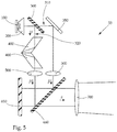
Fig. 5 ein weiteres Beispiel mit zwei unmittelbar hintereinander angeordneten Fresnelschen Parallelepipeden und einem LCoS. -
Fig. 1 zeigt eine Beleuchtungsvorrichtung 51, umfassend ein Leuchtmittel 100, welches in diesem Ausführungsbeispiel als LED ausgeführt ist und eingerichtet ist, Lichtstrahlen zu emittieren, wobei die Lichtstrahlen von einer dem Leuchtmittel 100 in Hauptabstrahlrichtung nachgeschalteten Vorsatzoptik 200 kollimierbar sind, d.h. dass die Lichtstrahlen des Leuchtmittels parallel bzw. im Wesentlichen parallel gerichtet werden. - Unter "Hauptabstrahlrichtung" ist die Richtung zu verstehen, in der das Leuchtmittel infolge seiner Richtwirkung am stärksten bzw. am meisten Licht abstrahlt.
- Weiters umfasst die Beleuchtungseinrichtung aus
Fig. 1 einen der Vorsatzoptik 200 nachgeschalteten, polarisierenden Strahlteiler 300, der die von der Vorsatzoptik 200 kollimierten Lichtstrahlen in einen ersten und einen zweiten linear polarisierten Strahlengang 310, 320 aufteilt, wobei die Polarisationsrichtungen der Strahlengänge 310, 320 90° verdreht zueinander sind. - Es sei angemerkt, dass der polarisierende Strahlteiler 300 in
Fig. 1 in einem 45°-Winkel zur Hauptabstrahlrichtung der durch die Vorsatzoptik 200 kollimierten Lichtstrahlen steht, jedoch auch andere Positionen des Strahlteilers 300 möglich sind. - Im Allgemeinen bezeichnet man linear senkrecht zur Einfallsebene polarisiertes Licht als transversale Komponente TE bzw. mit dem Kürzel "s". Linear parallel zur Einfallsebene polarisiertes Licht bezeichnet man in der Regel als transversalmagnetische Komponente TM bzw. mit dem Kürzel "p", wobei sich die Abkürzungen "s" und "p" in den Figuren zur besseren Übersicht wiederfinden.
- Der Begriff "Einfallsebene" ist ein bekannter Begriff aus der Optik und bezeichnet im Allgemeinen die Ebene, die von der Einfallsrichtung des auf eine Grenzfläche einfallenden Lichts und dem Lot auf diese Grenzfläche aufgespannt wird. Der Polarisationszustand des Lichts wird in der Regel bezüglich der Einfallsebene angegeben.
- Ferner ist ein erstes Mittel zur Polarisationsdrehung 400, welches nach dem polarisierenden Strahlteiler 300 im zweiten Strahlengang 320 positioniert und eingerichtet ist, die Polarisationsrichtung des zweiten Strahlengangs 320 um 90° zu verdrehen, sodass der zweite Strahlengang 320 die gleiche Polarisationsrichtung wie der erste Strahlengang 310 aufweist.
- Das erste Mittel zur Polarisationsdrehung 400 ist in diesem Beispiel als zwei Fresnelsche Parallelepipede ausgebildet, wobei die Parallelepipede unmittelbar hintereinander angeordnet sind, sodass Stirnflächen der jeweiligen Parallelepipede ohne einem Abstand zueinander angeordnet sind.
- Ein Fresnelsches Parallelepiped, welches in der Regel ein lichtdurchlässiger Körper ist, beispielsweise aus Kronglas, Polycarbonat oder Tarflon, ermöglicht, ein linear polarisiertes Licht durch zweifache Totalreflexion in zirkular polarisiertes Licht umzuwandeln.
- Hierzu wird linear polarisiertes Licht senkrecht bzw. orthogonal auf eine Stirnseite des Parallelepipeds gelenkt, wobei das Licht dadurch keine Richtungsänderung erfährt. Anschließend fällt das Licht auf eine erste schräge Längsfläche des Prismas, wobei der Einfallswinkel des Lichts auf diese Längsfläche größer als der Grenzwinkel einer Totalreflexion ist, und totalreflektiert wird.
- Die dabei auftretende Phasenverschiebung bewirkt, dass aus dem ursprünglich linear polarisierten Licht ein elliptisch polarisiertes Licht wird. Für die Erzeugung von zirkular polarisiertem Licht ist eine zweite Totalreflexion innerhalb des Prismas notwendig.
- Der Einfallswinkel ist abhängig vom Brechungsindex des eingesetzten Materials, beispielsweise Kronglas, dessen Brechungsindex 1,51 beträgt.
- Im Allgemeinen lässt sich zirkular polarisiertes Licht durch Summation von zwei senkrecht zueinander linear polarisierten Wellen gleicher Amplitude und passender Phasenverschiebung erhalten. In gleicher Weise kann man jede linear polarisierte Welle als Summe einer links- und rechtszirkular polarisierten Welle darstellen.
- Die mit einem Fresnelschen Parallelepiped erzeugte Phasendifferenz zeigt in weiten Bereichen nur eine geringe bis gar keine Abhängigkeit von der Wellenlänge des einfallenden Lichts, wodurch auch Lichtquellen zur Anwendung kommen können, die weißes Licht bzw. polychromatisches Licht emittieren, wobei unter "weißes Licht" Licht einer solchen Spektralzusammensetzung verstanden wird, welches beim Menschen den Farbeindruck "weiß" hervorruft.
- Bei zwei unmittelbar hintereinander angeordneten Fresnelschen Parallelepipeden, welche die gleichen Eigenschaften im Sinne von Material und Form aufweisen, treten insgesamt vier Totalreflexionen auf, welche das einfallende linear polarisierte Licht nach dem Austritt aus den beiden Prismen in ein um ein 90° verdrehtes linear polarisiertes Licht umwandeln, wobei das Licht seine Richtung beibehält.
- Weiters ist ein reflektives Mittel 350 im ersten Strahlengang 310 angeordnet, welches reflektive Mittel 350 den ersten Strahlengang 310 im Wesentlichen in die Richtung des durch das erste Mittel zur Polarisationsdrehung 400 veränderten zweiten Strahlengangs 320 umlenkt.
- Ferner umfasst die Beleuchtungsvorrichtung 51 ein einziges zweites Mittel zur Polarisationsdrehung 600, welches dem ersten Mittel zur Polarisationsdrehung 400 und dem reflektiven Mittel 350 nachgeschalten ist, wobei das zweite Mittel zur Polarisation 600 in dem Ausführungsbeispiel aus
Fig. 1 als Flüssigkristallelement ausgebildet ist, welches mehrere Segmente bzw. Flüssigkristalle umfasst, welche mittels elektrischer Signale in einen aktiven und einen inaktiven Zustand versetzbar sind, wobei die Polarisationsrichtung der Lichtstrahlen im aktiven Zustand drehbar ist, vorzugsweise um 90°, und im inaktiven Zustand keine Änderung erfährt. - Dem zweiten Mittel zur Polarisationsdrehung bzw. dem Flüssigkristallelement 600 sind zwei Optikelemente 500, beispielsweise Linsen oder Reflektoren, vorgelagert, welche je einem Strahlengang 310, 320 zugeordnet und eingerichtet sind, eine homogene Ausleuchtung des Flüssigkristallelements 600 durch die auf das Flüssigkristallelement 600 einfallenden Strahlengänge 310, 320 zu ermöglichen. In den gezeigten Beispielen sind die Optikelemente 500 als optische Linsen ausgebildet.
- Dem Flüssigkristallelement 600 ist ein Polarisationsfiltermittel 610 nachgeschalten, welches Polarisationsfiltermittel 610 eingerichtet ist, die von den Segmenten bzw. Flüssigkristallen des Flüssigkristallelements 600 hinsichtlich der Polarisationsrichtung gedrehten Lichtstrahlen zu transmittieren bzw. zu absorbieren/blockieren, wodurch das gewünschte Lichtbild bzw. Lichtverteilung erzeugt wird.
- Zur Erzeugung einer Lichtverteilung oder einer Teil-Lichtverteilung einer Lichtfunktion vor einem Kraftfahrzeug ist eine Projektionslinse 700 vorgesehen.
- Es kann vorgesehen sein, dass eine solche Beleuchtungsvorrichtung 51, 52, 53 zur Erzeugung der Lichtfunktion "Fernlicht" eingesetzt werden kann, wobei die Beleuchtungsvorrichtung 51, 52, 53 bei dieser Lichtfunktion "Fernlicht" eine Lichtverteilung erzeugt, welche in einem eingebauten Zustand der Beleuchtungsvorrichtung 51, 52, 53 in ein Kraftfahrzeug, vor dem Kraftfahrzeug eine den gesetzlichen Anforderungen entsprechende Fernlichtverteilung erzeugt.
- Es kann vorgesehen sein, dass eine solche Beleuchtungsvorrichtung 51, 52, 53 zur Erzeugung der Lichtfunktion "Abblendlicht" eingesetzt werden kann, wobei die Beleuchtungsvorrichtung bei dieser Lichtfunktion "Abblendlicht" eine Lichtverteilung erzeugt, welche in einem eingebauten Zustand der Beleuchtungsvorrichtung 51, 52, 53 in ein Kraftfahrzeug, vor dem Kraftfahrzeug eine den gesetzlichen Anforderungen entsprechende Abblendlichtverteilung erzeugt.
- Die oben genannten, aufgezählten Lichtfunktionen bzw. Lichtverteilungen sind nicht abschließend und beziehen sich auf das Ausführungsbeispiel in
Fig. 1 sowie weitere mögliche Ausführungsformen, wobei die Beleuchtungsvorrichtungen 51, 52, 53 auch Kombinationen dieser Lichtfunktionen erzeugen können und/oder nur eine Teillichtverteilung erzeugen, also beispielsweise nur einen Teil einer Fern-, Abblend-, Nebel-oder Tagfahrlichtverteilung. -
Fig. 2 zeigt ein weiteres Beispiel einer Beleuchtungsvorrichtung 52, wobei im Gegensatz zur Ausführungsform inFig. 1 das erste Mittel zur Polarisationsdrehung 400 als ein Fresnelsches Parallelepiped ausgebildet ist, wobei eine Stirnfläche 410 des Parallelepipeds 400 verspiegelt ist. - Hierbei wird das durch einen polarisierenden Strahlteiler 300 senkrecht linear polarisierte Licht, welches in
Fig. 2 mit "s" gekennzeichnet ist, in das Fresnelsche Parallelepiped 400 einkoppelt und nach zweimaliger Totalreflexion auf die verspiegelte Stirnfläche 410 trifft, wobei das Licht bzw. die Lichtstrahlen in die entgegengesetzte Richtung gespiegelt werden und wiederum zwei Totalreflexionen innerhalb des Parallelepipeds 400 erfährt und eine um 90° gedrehte Polarisationsrichtung, also ein parallel linear polarisiertes Licht, was mit "p" inFig. 2 gekennzeichnet ist, aufweist, bevor es aus dem Parallelepiped auskoppelt bzw. austritt. - Die Auskoppelrichtung bzw. die Austrittsrichtung ist hierbei der Eintrittsrichtung bzw. der Einkoppelrichtung des Lichts entgegengesetzt, wie in
Fig. 2 dargestellt ist. - Das aus dem Fresnelsches Parallelepiped 400 austretende, parallel linear polarisierte Licht wird von dem polarisierenden Strahlteiler 300 unverändert transmittiert.
- Der übrige Aufbau des in
Fig. 2 gezeigten Beispiels gleicht im Wesentlichen dem Aufbau des Beispiels ausFig. 1 . -
Fig. 3 zeigt eine Detailansicht des Aufbaus ausFig. 2 , wobei das Leuchtmittel 100 aus mehreren LEDs gebildet ist, die jeweils eine nachgeschaltete Vorsatzoptik 200 umfassen. Als Vorsatzoptik 200 kann jeweils beispielsweise eine TIR-Linse vorgesehen sein. -
Fig. 4 zeigt eine entlang der x-Achse dargestellte Perspektive der Detailansicht ausFig. 3 , wobei zu erkennen ist, dass das Leuchtmittel 100 aus dem Beispiel inFig. 3 und 4 sowohl eine Reihe von Lichtquellen entlang der x-Achse als auch eine Reihe von Lichtquellen entlang der z-Achse aufweist. - Das Leuchtmittel 100 ist gewissermaßen aus einer Lichtquellen-Matrix gebildet, wobei auch vorgesehen sein kann, dass das Leuchtmittel 100 nur aus einer Reihe von Lichtquellen bzw. einem Lichtquellen-Array gebildet sein kann.
-
Fig. 5 zeigt eine Beleuchtungsvorrichtung 53, umfassend ein Leuchtmittel 100, welches in diesem Ausführungsbeispiel als LED ausgeführt ist und eingerichtet ist, Lichtstrahlen zu emittieren, wobei die Lichtstrahlen von einer dem Leuchtmittel 100 in Hauptabstrahlrichtung nachgeschalteten Vorsatzoptik 200 kollimierbar sind, d.h. dass die Lichtstrahlen des Leuchtmittels parallel bzw. im Wesentlichen parallel gerichtet werden. - Weiters umfasst die Beleuchtungseinrichtung aus
Fig. 5 einen der Vorsatzoptik 200 nachgeschalteten, polarisierenden Strahlteiler 300, der die von der Vorsatzoptik 200 kollimierten Lichtstrahlen in einen ersten und einen zweiten linear polarisierten Strahlengang 310, 320 aufteilt, wobei die Polarisationsrichtungen der Strahlengänge 310, 320 90° verdreht zueinander sind. - Es sei angemerkt, dass der polarisierende Strahlteiler 300 in
Fig. 5 in einem 45°-Winkel zur Hauptabstrahlrichtung der durch die Vorsatzoptik 200 kollimierten Lichtstrahlen steht, jedoch auch andere Positionen des Strahlteilers 300 möglich sind. - Ferner ist ein erstes Mittel zur Polarisationsdrehung 400, welches nach dem polarisierenden Strahlteiler 300 im zweiten Strahlengang 320 positioniert und eingerichtet ist, die Polarisationsrichtung des zweiten Strahlengangs 320 um 90° zu verdrehen, sodass der zweite Strahlengang 320 die gleiche Polarisationsrichtung wie der erste Strahlengang 310 aufweist.
- Das erste Mittel zur Polarisationsdrehung 400 ist in diesem Beispiel als zwei Fresnelsche Parallelepipede ausgebildet, wobei die Parallelepipede unmittelbar hintereinander angeordnet sind, sodass Stirnflächen der jeweiligen Parallelepipede ohne einem Abstand zueinander angeordnet sind.
- Weiters ist ein reflektives Mittel 350 im ersten Strahlengang 310 angeordnet, welches reflektive Mittel 350 den ersten Strahlengang 310 im Wesentlichen in die Richtung des durch das erste Mittel zur Polarisationsdrehung 400 veränderten zweiten Strahlengangs 320 umlenkt.
- Ferner umfasst die Beleuchtungsvorrichtung 53 ein Polarisationsfiltermittel 660, welches den Fresnelschen Parallelepipeden 400 und dem reflektiven Mittel 350 nachgeschalten ist, wobei das Polarisationsfiltermittel 660 die darauf auftreffenden Strahlengänge 310, 320, welche die gleiche Polarisationsrichtung aufweisen, auf ein zweites Mittel zur Polarisationsdrehung 650 umlenkt bzw. reflektiert. Das Polarisationsfiltermittel 660 ist in dem Beispiel aus
Fig. 5 derart eingerichtet, dass es wie ein polarisierender Strahlteiler, ähnlich dem polarisierenden Strahlteiler 300 aus den vorherigen Beispielen, funktioniert. - Das zweite Mittel zur Polarisationsdrehung 650 ist in
Fig. 5 als LCoS-Element ausgebildet. Im Gegensatz zu LC-Displays bzw. dem Flüssigkristallelement 600 aus den vorigen Ausführungsbeispielen lässt ein LCoS 650 (Liquid Crystal on Silicon) Licht nicht durch, sondern reflektiert es, wobei das LCoS 650 wie das Flüssigkristallelement 600 in einen aktiven bzw. inaktiven Zustand versetzt werden kann. Nähere Erläuterungen bezüglich des inaktiven bzw. aktiven Zustands sind den Ausführungen bezüglichFig. 1 zu entnehmen. - Die Auskoppelrichtung bzw. die Austrittsrichtung der Strahlengänge 310, 320 aus dem LCoS-Element 650 ist hierbei der Eintrittsrichtung bzw. der Einkoppelrichtung der Strahlengänge 310, 320 bzw. des Lichts entgegengesetzt, wie in
Fig. 5 dargestellt ist. - Das aus den Segmenten bzw. Flüssigkristallen des LCoS-Elements 650 austretende, hinsichtlich seiner Polarisationsrichtung veränderte Licht wird von dem Polarisationsfiltermittel 660 transmittiert bzw. blockiert, wodurch das gewünschte Lichtbild erzeugt wird, wobei dem Polarisationsfiltermittel 660 ein Projektionslinse 700 nachgeschalten ist, welcher zur Erzeugung einer Lichtverteilung oder einer Teil-Lichtverteilung einer Lichtfunktion vor einem Kraftfahrzeug vorgesehen ist.
- Ferner sind dem Polarisationsfiltermittel 660 zwei Optikelemente 500 vorgelagert, welche je einem Strahlengang 310, 320 zugeordnet und eingerichtet sind, eine homogene Ausleuchtung des Polarisationsfiltermittels 660 durch die auf das Polarisationsfiltermittel 660 einfallenden Strahlengänge 310, 320 zu ermöglichen.
- Es sei angemerkt, dass alle in den Figuren gezeigten Beispiele in einem und als Teil eines Kraftfahrzeugscheinwerfers vorgesehen sein können.
-
- Beleuchtungsvorrichtung
- 51, 52, 53
- Leuchtmittel
- 100
- Vorsatzoptik
- 200
- Polarisierenden Strahlteiler
- 300
- Erster Strahlengang
- 310
- Zweiter Strahlengang
- 320
- Reflektives Mittel
- 350
- Erstes Mittel zur Polarisationsdrehung
- 400
- Fresnelsches Parallelepiped
- 400
- Verspiegelte Stirnfläche
- 410
- Optikelement
- 500
- Zweites Mittel zur Polarisationsdrehung
- 600
- Flüssigkristallelement
- 600
- LCoS
- 650
- Projektionslinse
- 700
Claims (15)
- Beleuchtungsvorrichtung (51, 52, 53) für einen Kraftfahrzeugscheinwerfer, welche Beleuchtungsvorrichtung umfasst:- ein Leuchtmittel (100), das eingerichtet ist, Lichtstrahlen zu emittieren, wobei die Lichtstrahlen von zumindest einer dem Leuchtmittel in Hauptabstrahlrichtung nachgeschalteten Vorsatzoptik (200) kollimierbar sind,- ein der zumindest einen Vorsatzoptik (200) nachgeschalteter polarisierender Strahlteiler (300), der die von der Vorsatzoptik (200) kollimierten Lichtstrahlen in einen ersten und einen zweiten linear polarisierten Strahlengang (310, 320) aufteilt, wobei die Polarisationsrichtungen der Strahlengänge (310, 320) 90° zueinander verdreht sind,- ein erstes Mittel zur Polarisationsdrehung (400), welches eingerichtet ist, die Polarisationsrichtung des zweiten Strahlengangs (320) um 90° zu verdrehen, sodass der zweite Strahlengang (320) die Polarisationsrichtung des ersten Strahlengangs (310) aufweist,- ein reflektives Mittel (350), welches eingerichtet ist, den ersten Strahlengang (310) im Wesentlichen in die Richtung des durch das erste Mittel zur Polarisationsdrehung (400) veränderten zweiten Strahlengangs (320) umzulenken,- ein einziges dem ersten Mittel zur Polarisationsdrehung (400) und dem reflektiven Mittel (350) nachgeschaltetes zweites Mittel zur Polarisationsdrehung (600), welches zumindest ein Segment umfasst, welches mittels elektrischer Signale in einen aktiven und einen inaktiven Zustand versetzbar ist, wobei die Polarisation von Lichtstrahlen im aktiven Zustand um 90° drehbar ist und im inaktiven Zustand keine Änderung erfährt,- ein Polarisationsfiltermittel (610), welches dem zweiten Mittel zur Polarisationsdrehung (600) nachgeschalten ist, welches Polarisationsfiltermittel (610) eingerichtet ist, die von dem zweiten Mittel zur Polarisationsdrehung (600) im aktiven bzw. inaktiven Zustand hinsichtlich der Polarisation gedrehten Lichtstrahlen zu transmittieren bzw. zu blockieren, und- zumindest eine Projektionslinse (700), welche zur Erzeugung einer Lichtverteilung oder einer Teil-Lichtverteilung einer Lichtfunktion vor einem Kraftfahrzeug vorgesehen ist.
- Beleuchtungsvorrichtung nach Anspruch 1, dadurch gekennzeichnet, dass das Leuchtmittel (100) zumindest eine Lichtquelle umfasst.
- Beleuchtungsvorrichtung nach Anspruch 1 oder 2, dadurch gekennzeichnet, dass das Leuchtmittel (100) zwei oder mehrere Lichtquellen umfasst.
- Beleuchtungsvorrichtung nach Anspruch 2 oder 3, dadurch gekennzeichnet, dass jeder Lichtquelle eine eigene Vorsatzoptik (200) zugeordnet ist.
- Beleuchtungsvorrichtung nach einem der Ansprüche 2 bis 4, dadurch gekennzeichnet, dass die zumindest eine Lichtquelle als LED ausgebildet ist.
- Beleuchtungsvorrichtung nach einem der Ansprüche 1 bis 5, dadurch gekennzeichnet, dass die zumindest eine Vorsatzoptik (200) als TIR-Linse ausgebildet ist.
- Beleuchtungsvorrichtung nach einem der Ansprüche 1 bis 6, dadurch gekennzeichnet, dass das erste Mittel zur Polarisationsdrehung (400) als Fresnelsches Parallelepiped ausgebildet ist, wobei eine Stirnfläche des Parallelepipeds verspiegelt ist.
- Beleuchtungsvorrichtung nach einem der Ansprüche 1 bis 7, dadurch gekennzeichnet, dass das erste Mittel zur Polarisationsdrehung (400) als zwei Fresnelsche Parallelepipede ausgebildet ist, wobei die zwei Parallelepipede vorzugsweise unmittelbar hintereinander angeordnet sind.
- Beleuchtungsvorrichtung nach Anspruch 7 oder 8, dadurch gekennzeichnet, dass das Fresnelsche Parallelepiped aus Kronglas, Polycarbonat oder Tarflon gebildet ist.
- Beleuchtungsvorrichtung nach einem der Ansprüche 1 bis 9, dadurch gekennzeichnet, dass das zweite Mittel zur Polarisationsdrehung (600) als Flüssigkristallelement ausgebildet ist.
- Beleuchtungsvorrichtung nach einem der Ansprüche 1 bis 10, dadurch gekennzeichnet, dass das reflektive Mittel (350) als Spiegel ausgebildet ist.
- Beleuchtungsvorrichtung nach einem der Ansprüche 1 bis 11, dadurch gekennzeichnet, dass das zweite Mittel zur Polarisationsdrehung (600) ein LCoS-Element ist.
- Beleuchtungsvorrichtung nach einem der Ansprüche 1 bis 12, dadurch gekennzeichnet, dass dem zweiten Mittel zur Polarisationsdrehung (600) zumindest ein Optikelement (500) vorgelagert ist, welches eingerichtet ist, eine homogene Ausleuchtung des zweiten Mittels zur Polarisationsdrehung (600) durch die auf das zweite Mittel zur Polarisationsdrehung (600) einfallenden Strahlengänge zu ermöglichen.
- Beleuchtungsvorrichtung nach Anspruch 13, dadurch gekennzeichnet, dass dem zweiten Mittel zur Polarisationsdrehung (600) zwei Optikelemente (500) vorgelagert sind, wobei die Optikelemente je einem Strahlengang (310, 320) zugeordnet sind.
- Kraftfahrzeugscheinwerfer, umfassend zumindest eine Beleuchtungsvorrichtung gemäß einem der Ansprüche 1 bis 14.
Priority Applications (6)
| Application Number | Priority Date | Filing Date | Title |
|---|---|---|---|
| EP17203860.6A EP3489577B1 (de) | 2017-11-27 | 2017-11-27 | Beleuchtungsvorrichtung für einen kraftfahrzeugscheinwerfer |
| CN201880076317.XA CN111373196A (zh) | 2017-11-27 | 2018-10-11 | 用于机动车前照灯的照明装置 |
| PCT/EP2018/077704 WO2019101426A1 (de) | 2017-11-27 | 2018-10-11 | Beleuchtungsvorrichtung für einen kraftfahrzeugscheinwerfer |
| US16/766,889 US10969075B2 (en) | 2017-11-27 | 2018-10-11 | Illumination device for a motor vehicle headlight |
| JP2020528877A JP6976437B2 (ja) | 2017-11-27 | 2018-10-11 | 自動車両用投光装置のための照明装置 |
| KR1020207016450A KR102405591B1 (ko) | 2017-11-27 | 2018-10-11 | 자동차 헤드램프용 조명 장치 |
Applications Claiming Priority (1)
| Application Number | Priority Date | Filing Date | Title |
|---|---|---|---|
| EP17203860.6A EP3489577B1 (de) | 2017-11-27 | 2017-11-27 | Beleuchtungsvorrichtung für einen kraftfahrzeugscheinwerfer |
Publications (2)
| Publication Number | Publication Date |
|---|---|
| EP3489577A1 true EP3489577A1 (de) | 2019-05-29 |
| EP3489577B1 EP3489577B1 (de) | 2021-11-24 |
Family
ID=60473435
Family Applications (1)
| Application Number | Title | Priority Date | Filing Date |
|---|---|---|---|
| EP17203860.6A Not-in-force EP3489577B1 (de) | 2017-11-27 | 2017-11-27 | Beleuchtungsvorrichtung für einen kraftfahrzeugscheinwerfer |
Country Status (6)
| Country | Link |
|---|---|
| US (1) | US10969075B2 (de) |
| EP (1) | EP3489577B1 (de) |
| JP (1) | JP6976437B2 (de) |
| KR (1) | KR102405591B1 (de) |
| CN (1) | CN111373196A (de) |
| WO (1) | WO2019101426A1 (de) |
Families Citing this family (2)
| Publication number | Priority date | Publication date | Assignee | Title |
|---|---|---|---|---|
| CN116039490B (zh) * | 2021-10-28 | 2026-06-19 | 引望智能技术有限公司 | 一种车灯组件及交通工具 |
| KR20240150625A (ko) * | 2023-04-06 | 2024-10-16 | 김태형 | 차량용 헤드 램프 조립체 |
Citations (5)
| Publication number | Priority date | Publication date | Assignee | Title |
|---|---|---|---|---|
| EP1351015A2 (de) * | 2002-04-05 | 2003-10-08 | Honda Giken Kogyo Kabushiki Kaisha | Scheinwerfer |
| US20160131920A1 (en) * | 2014-11-06 | 2016-05-12 | Government Of The United States, As Represented By The Secretary Of The Air Force | Universal Polarization Converter |
| EP3032168A1 (de) * | 2014-12-11 | 2016-06-15 | Stanley Electric Co., Ltd. | Fahrzeugscheinwerfereinheit |
| DE102015115339A1 (de) * | 2015-09-11 | 2017-03-16 | Hella Kgaa Hueck & Co. | Beleuchtungsvorrichtung für Fahrzeuge |
| DE102015115348A1 (de) * | 2015-09-11 | 2017-03-16 | Hella Kgaa Hueck & Co. | Beleuchtungseinrichtung für ein Kraftfahrzeug |
Family Cites Families (14)
| Publication number | Priority date | Publication date | Assignee | Title |
|---|---|---|---|---|
| US3432223A (en) * | 1963-04-10 | 1969-03-11 | Nippon Electric Co | Modulator for a light beam |
| FR2298208A1 (fr) * | 1975-01-15 | 1976-08-13 | Comp Generale Electricite | Chaine laser de puissance |
| JPH04331913A (ja) * | 1991-05-07 | 1992-11-19 | Canon Inc | 偏光照明素子および該素子を有する投写型表示装置 |
| JPH04355323A (ja) * | 1991-06-03 | 1992-12-09 | Toshiba Corp | 光ファイバセンサ |
| JPH10221008A (ja) * | 1997-02-06 | 1998-08-21 | Nikon Corp | 偏光光学素子およびそれを用いた光波干渉測定装置 |
| JP2004136838A (ja) * | 2002-10-21 | 2004-05-13 | Toyota Industries Corp | 車両用の投射装置及び表示装置 |
| JP2006285043A (ja) * | 2005-04-01 | 2006-10-19 | Yamaha Corp | 光源装置 |
| JP2007199351A (ja) * | 2006-01-26 | 2007-08-09 | Nikon Corp | 表示システム、表示装置およびカメラ |
| CN101021447A (zh) * | 2007-03-15 | 2007-08-22 | 中国科学院上海光学精密机械研究所 | 测量1/4波片的相位延迟和快轴方向的方法和装置 |
| CN201032473Y (zh) * | 2007-03-15 | 2008-03-05 | 中国科学院上海光学精密机械研究所 | 测量1/4波片的相位延迟和快轴方向的装置 |
| CN101688652B (zh) * | 2007-05-07 | 2012-05-30 | 皇家飞利浦电子股份有限公司 | 具有改善的散热和可制造性的表面照明led基照明器材 |
| US8025416B2 (en) * | 2008-02-18 | 2011-09-27 | 3D4K Displays, Inc. | Integrated optical polarization combining prism for projection displays |
| JP4711009B2 (ja) * | 2008-10-16 | 2011-06-29 | ソニー株式会社 | 光学的測定装置 |
| WO2011146267A2 (en) * | 2010-05-19 | 2011-11-24 | 3M Innovative Properties Company | Polarized projection illuminator |
-
2017
- 2017-11-27 EP EP17203860.6A patent/EP3489577B1/de not_active Not-in-force
-
2018
- 2018-10-11 US US16/766,889 patent/US10969075B2/en not_active Expired - Fee Related
- 2018-10-11 CN CN201880076317.XA patent/CN111373196A/zh active Pending
- 2018-10-11 JP JP2020528877A patent/JP6976437B2/ja not_active Expired - Fee Related
- 2018-10-11 WO PCT/EP2018/077704 patent/WO2019101426A1/de not_active Ceased
- 2018-10-11 KR KR1020207016450A patent/KR102405591B1/ko active Active
Patent Citations (5)
| Publication number | Priority date | Publication date | Assignee | Title |
|---|---|---|---|---|
| EP1351015A2 (de) * | 2002-04-05 | 2003-10-08 | Honda Giken Kogyo Kabushiki Kaisha | Scheinwerfer |
| US20160131920A1 (en) * | 2014-11-06 | 2016-05-12 | Government Of The United States, As Represented By The Secretary Of The Air Force | Universal Polarization Converter |
| EP3032168A1 (de) * | 2014-12-11 | 2016-06-15 | Stanley Electric Co., Ltd. | Fahrzeugscheinwerfereinheit |
| DE102015115339A1 (de) * | 2015-09-11 | 2017-03-16 | Hella Kgaa Hueck & Co. | Beleuchtungsvorrichtung für Fahrzeuge |
| DE102015115348A1 (de) * | 2015-09-11 | 2017-03-16 | Hella Kgaa Hueck & Co. | Beleuchtungseinrichtung für ein Kraftfahrzeug |
Also Published As
| Publication number | Publication date |
|---|---|
| US10969075B2 (en) | 2021-04-06 |
| EP3489577B1 (de) | 2021-11-24 |
| JP6976437B2 (ja) | 2021-12-08 |
| WO2019101426A1 (de) | 2019-05-31 |
| US20200363030A1 (en) | 2020-11-19 |
| JP2021504900A (ja) | 2021-02-15 |
| CN111373196A (zh) | 2020-07-03 |
| KR20200088376A (ko) | 2020-07-22 |
| KR102405591B1 (ko) | 2022-06-07 |
Similar Documents
| Publication | Publication Date | Title |
|---|---|---|
| DE69028497T2 (de) | Polarisierendes Beleuchtungsgerät | |
| DE102012224079B4 (de) | Lichtleiter mit einer bandförmigen Lichtaustrittsfläche | |
| DE102012212436B4 (de) | Lichtmodul für eine Projektionsvorrichtung und Verfahren zur Generierung des Blauanteils in einem Lichtmodul für eine Projektionsvorrichtung | |
| DE102013207850A1 (de) | Lichtmodul für einen Kraftfahrzeugscheinwerfer | |
| WO2017042345A1 (de) | Beleuchtungsvorrichtung für fahrzeuge | |
| EP3473918B1 (de) | Beleuchtungsvorrichtung für einen kraftfahrzeugscheinwerfer | |
| DE102014218540B4 (de) | Fahrzeugleuchte und Verfahren zum Bereitstellen einer Lichtfunktion mittels einer Fahrzeugleuchte | |
| WO2017036787A1 (de) | Fahrzeugleuchte und verfahren zum bereitstellen einer lichtfunktion mittels einer fahrzeugleuchte | |
| EP3489577B1 (de) | Beleuchtungsvorrichtung für einen kraftfahrzeugscheinwerfer | |
| DE102015115339A1 (de) | Beleuchtungsvorrichtung für Fahrzeuge | |
| DE102016102991A1 (de) | Kraftfahrzeug-Scheinwerfer mit einem Flüssigkristalldisplay | |
| DE102016211691A1 (de) | Vorrichtung und Verfahren zum Erzeugen einer Ausgangslichtemission | |
| DE102020101598B4 (de) | Lichtmodul für einen Kraftfahrzeugscheinwerfer mit einem LCD-Display und zwei Polarisationsfiltern | |
| WO2025031998A1 (de) | Leuchtvorrichtung und kraftfahrzeugleuchte | |
| DE102017106441A1 (de) | Kraftfahrzeugleuchte mit einem flächigen Lichtleiter | |
| DE102016117967B4 (de) | Leuchteinrichtung für ein Fahrzeug | |
| WO2016091795A1 (de) | Beleuchtungsvorrichtung für fahrzeuge | |
| DE102020204577A1 (de) | Lichtleiteranordnung, Kantenauskopplungselement und Beleuchtungssystem für ein Fahrzeug | |
| EP3900980A1 (de) | Fahrzeugleuchte | |
| DE102021214549B3 (de) | Head-Up-Display Bilderzeugungseinheit mit Faltspiegel | |
| EP4198610A1 (de) | Head-up-display bilderzeugungseinheit mit faltspiegel | |
| DE102021213134A1 (de) | Anzeigeeinrichtung für einen Beifahrer für ein Fahrzeug und Verfahren zum Betreiben einer Anzeigeeinrichtung | |
| DE102015202595A1 (de) | Beleuchtungseinrichtung eines Fahrzeugs | |
| DE973383C (de) | Blendungsfreier Scheinwerfer und Nebelscheinwerfer mit Duennschichtpolarisatoren | |
| DE102012025918B4 (de) | Lichtmodul für eine Projektionsvorrichtung und Verfahren zur Generierung des Blauanteils in einem Lichtmodul für eine Projektionsvorrichtung |
Legal Events
| Date | Code | Title | Description |
|---|---|---|---|
| PUAI | Public reference made under article 153(3) epc to a published international application that has entered the european phase |
Free format text: ORIGINAL CODE: 0009012 |
|
| STAA | Information on the status of an ep patent application or granted ep patent |
Free format text: STATUS: THE APPLICATION HAS BEEN PUBLISHED |
|
| AK | Designated contracting states |
Kind code of ref document: A1 Designated state(s): AL AT BE BG CH CY CZ DE DK EE ES FI FR GB GR HR HU IE IS IT LI LT LU LV MC MK MT NL NO PL PT RO RS SE SI SK SM TR |
|
| AX | Request for extension of the european patent |
Extension state: BA ME |
|
| STAA | Information on the status of an ep patent application or granted ep patent |
Free format text: STATUS: REQUEST FOR EXAMINATION WAS MADE |
|
| 17P | Request for examination filed |
Effective date: 20190930 |
|
| RBV | Designated contracting states (corrected) |
Designated state(s): AL AT BE BG CH CY CZ DE DK EE ES FI FR GB GR HR HU IE IS IT LI LT LU LV MC MK MT NL NO PL PT RO RS SE SI SK SM TR |
|
| RIC1 | Information provided on ipc code assigned before grant |
Ipc: F21S 41/64 20180101AFI20210728BHEP Ipc: F21S 41/135 20180101ALI20210728BHEP Ipc: F21V 9/14 20060101ALI20210728BHEP Ipc: F21Y 115/10 20160101ALN20210728BHEP |
|
| GRAP | Despatch of communication of intention to grant a patent |
Free format text: ORIGINAL CODE: EPIDOSNIGR1 |
|
| STAA | Information on the status of an ep patent application or granted ep patent |
Free format text: STATUS: GRANT OF PATENT IS INTENDED |
|
| RIC1 | Information provided on ipc code assigned before grant |
Ipc: F21Y 115/10 20160101ALN20210907BHEP Ipc: F21V 9/14 20060101ALI20210907BHEP Ipc: F21S 41/135 20180101ALI20210907BHEP Ipc: F21S 41/64 20180101AFI20210907BHEP |
|
| GRAS | Grant fee paid |
Free format text: ORIGINAL CODE: EPIDOSNIGR3 |
|
| GRAA | (expected) grant |
Free format text: ORIGINAL CODE: 0009210 |
|
| STAA | Information on the status of an ep patent application or granted ep patent |
Free format text: STATUS: THE PATENT HAS BEEN GRANTED |
|
| INTG | Intention to grant announced |
Effective date: 20211005 |
|
| AK | Designated contracting states |
Kind code of ref document: B1 Designated state(s): AL AT BE BG CH CY CZ DE DK EE ES FI FR GB GR HR HU IE IS IT LI LT LU LV MC MK MT NL NO PL PT RO RS SE SI SK SM TR |
|
| REG | Reference to a national code |
Ref country code: GB Ref legal event code: FG4D Free format text: NOT ENGLISH |
|
| REG | Reference to a national code |
Ref country code: AT Ref legal event code: REF Ref document number: 1450132 Country of ref document: AT Kind code of ref document: T Effective date: 20211215 |
|
| REG | Reference to a national code |
Ref country code: DE Ref legal event code: R096 Ref document number: 502017012090 Country of ref document: DE |
|
| REG | Reference to a national code |
Ref country code: IE Ref legal event code: FG4D Free format text: LANGUAGE OF EP DOCUMENT: GERMAN |
|
| REG | Reference to a national code |
Ref country code: LT Ref legal event code: MG9D |
|
| REG | Reference to a national code |
Ref country code: NL Ref legal event code: MP Effective date: 20211124 |
|
| PG25 | Lapsed in a contracting state [announced via postgrant information from national office to epo] |
Ref country code: RS Free format text: LAPSE BECAUSE OF FAILURE TO SUBMIT A TRANSLATION OF THE DESCRIPTION OR TO PAY THE FEE WITHIN THE PRESCRIBED TIME-LIMIT Effective date: 20211124 Ref country code: LT Free format text: LAPSE BECAUSE OF FAILURE TO SUBMIT A TRANSLATION OF THE DESCRIPTION OR TO PAY THE FEE WITHIN THE PRESCRIBED TIME-LIMIT Effective date: 20211124 Ref country code: FI Free format text: LAPSE BECAUSE OF FAILURE TO SUBMIT A TRANSLATION OF THE DESCRIPTION OR TO PAY THE FEE WITHIN THE PRESCRIBED TIME-LIMIT Effective date: 20211124 Ref country code: BG Free format text: LAPSE BECAUSE OF FAILURE TO SUBMIT A TRANSLATION OF THE DESCRIPTION OR TO PAY THE FEE WITHIN THE PRESCRIBED TIME-LIMIT Effective date: 20220224 |
|
| PG25 | Lapsed in a contracting state [announced via postgrant information from national office to epo] |
Ref country code: IS Free format text: LAPSE BECAUSE OF FAILURE TO SUBMIT A TRANSLATION OF THE DESCRIPTION OR TO PAY THE FEE WITHIN THE PRESCRIBED TIME-LIMIT Effective date: 20220324 Ref country code: SE Free format text: LAPSE BECAUSE OF FAILURE TO SUBMIT A TRANSLATION OF THE DESCRIPTION OR TO PAY THE FEE WITHIN THE PRESCRIBED TIME-LIMIT Effective date: 20211124 Ref country code: PT Free format text: LAPSE BECAUSE OF FAILURE TO SUBMIT A TRANSLATION OF THE DESCRIPTION OR TO PAY THE FEE WITHIN THE PRESCRIBED TIME-LIMIT Effective date: 20220324 Ref country code: PL Free format text: LAPSE BECAUSE OF FAILURE TO SUBMIT A TRANSLATION OF THE DESCRIPTION OR TO PAY THE FEE WITHIN THE PRESCRIBED TIME-LIMIT Effective date: 20211124 Ref country code: NO Free format text: LAPSE BECAUSE OF FAILURE TO SUBMIT A TRANSLATION OF THE DESCRIPTION OR TO PAY THE FEE WITHIN THE PRESCRIBED TIME-LIMIT Effective date: 20220224 Ref country code: NL Free format text: LAPSE BECAUSE OF FAILURE TO SUBMIT A TRANSLATION OF THE DESCRIPTION OR TO PAY THE FEE WITHIN THE PRESCRIBED TIME-LIMIT Effective date: 20211124 Ref country code: LV Free format text: LAPSE BECAUSE OF FAILURE TO SUBMIT A TRANSLATION OF THE DESCRIPTION OR TO PAY THE FEE WITHIN THE PRESCRIBED TIME-LIMIT Effective date: 20211124 Ref country code: HR Free format text: LAPSE BECAUSE OF FAILURE TO SUBMIT A TRANSLATION OF THE DESCRIPTION OR TO PAY THE FEE WITHIN THE PRESCRIBED TIME-LIMIT Effective date: 20211124 Ref country code: GR Free format text: LAPSE BECAUSE OF FAILURE TO SUBMIT A TRANSLATION OF THE DESCRIPTION OR TO PAY THE FEE WITHIN THE PRESCRIBED TIME-LIMIT Effective date: 20220225 Ref country code: ES Free format text: LAPSE BECAUSE OF FAILURE TO SUBMIT A TRANSLATION OF THE DESCRIPTION OR TO PAY THE FEE WITHIN THE PRESCRIBED TIME-LIMIT Effective date: 20211124 |
|
| REG | Reference to a national code |
Ref country code: CH Ref legal event code: PL |
|
| PG25 | Lapsed in a contracting state [announced via postgrant information from national office to epo] |
Ref country code: SM Free format text: LAPSE BECAUSE OF FAILURE TO SUBMIT A TRANSLATION OF THE DESCRIPTION OR TO PAY THE FEE WITHIN THE PRESCRIBED TIME-LIMIT Effective date: 20211124 Ref country code: SK Free format text: LAPSE BECAUSE OF FAILURE TO SUBMIT A TRANSLATION OF THE DESCRIPTION OR TO PAY THE FEE WITHIN THE PRESCRIBED TIME-LIMIT Effective date: 20211124 Ref country code: RO Free format text: LAPSE BECAUSE OF FAILURE TO SUBMIT A TRANSLATION OF THE DESCRIPTION OR TO PAY THE FEE WITHIN THE PRESCRIBED TIME-LIMIT Effective date: 20211124 Ref country code: LU Free format text: LAPSE BECAUSE OF NON-PAYMENT OF DUE FEES Effective date: 20211127 Ref country code: EE Free format text: LAPSE BECAUSE OF FAILURE TO SUBMIT A TRANSLATION OF THE DESCRIPTION OR TO PAY THE FEE WITHIN THE PRESCRIBED TIME-LIMIT Effective date: 20211124 Ref country code: DK Free format text: LAPSE BECAUSE OF FAILURE TO SUBMIT A TRANSLATION OF THE DESCRIPTION OR TO PAY THE FEE WITHIN THE PRESCRIBED TIME-LIMIT Effective date: 20211124 Ref country code: CZ Free format text: LAPSE BECAUSE OF FAILURE TO SUBMIT A TRANSLATION OF THE DESCRIPTION OR TO PAY THE FEE WITHIN THE PRESCRIBED TIME-LIMIT Effective date: 20211124 Ref country code: BE Free format text: LAPSE BECAUSE OF NON-PAYMENT OF DUE FEES Effective date: 20211130 |
|
| REG | Reference to a national code |
Ref country code: BE Ref legal event code: MM Effective date: 20211130 |
|
| REG | Reference to a national code |
Ref country code: DE Ref legal event code: R097 Ref document number: 502017012090 Country of ref document: DE |
|
| PG25 | Lapsed in a contracting state [announced via postgrant information from national office to epo] |
Ref country code: MC Free format text: LAPSE BECAUSE OF FAILURE TO SUBMIT A TRANSLATION OF THE DESCRIPTION OR TO PAY THE FEE WITHIN THE PRESCRIBED TIME-LIMIT Effective date: 20211124 Ref country code: LI Free format text: LAPSE BECAUSE OF NON-PAYMENT OF DUE FEES Effective date: 20211130 Ref country code: CH Free format text: LAPSE BECAUSE OF NON-PAYMENT OF DUE FEES Effective date: 20211130 |
|
| PLBE | No opposition filed within time limit |
Free format text: ORIGINAL CODE: 0009261 |
|
| STAA | Information on the status of an ep patent application or granted ep patent |
Free format text: STATUS: NO OPPOSITION FILED WITHIN TIME LIMIT |
|
| GBPC | Gb: european patent ceased through non-payment of renewal fee |
Effective date: 20220224 |
|
| PG25 | Lapsed in a contracting state [announced via postgrant information from national office to epo] |
Ref country code: IE Free format text: LAPSE BECAUSE OF NON-PAYMENT OF DUE FEES Effective date: 20211127 Ref country code: AL Free format text: LAPSE BECAUSE OF FAILURE TO SUBMIT A TRANSLATION OF THE DESCRIPTION OR TO PAY THE FEE WITHIN THE PRESCRIBED TIME-LIMIT Effective date: 20211124 |
|
| 26N | No opposition filed |
Effective date: 20220825 |
|
| PG25 | Lapsed in a contracting state [announced via postgrant information from national office to epo] |
Ref country code: SI Free format text: LAPSE BECAUSE OF FAILURE TO SUBMIT A TRANSLATION OF THE DESCRIPTION OR TO PAY THE FEE WITHIN THE PRESCRIBED TIME-LIMIT Effective date: 20211124 |
|
| PG25 | Lapsed in a contracting state [announced via postgrant information from national office to epo] |
Ref country code: GB Free format text: LAPSE BECAUSE OF NON-PAYMENT OF DUE FEES Effective date: 20220224 |
|
| PG25 | Lapsed in a contracting state [announced via postgrant information from national office to epo] |
Ref country code: IT Free format text: LAPSE BECAUSE OF FAILURE TO SUBMIT A TRANSLATION OF THE DESCRIPTION OR TO PAY THE FEE WITHIN THE PRESCRIBED TIME-LIMIT Effective date: 20211124 |
|
| PG25 | Lapsed in a contracting state [announced via postgrant information from national office to epo] |
Ref country code: CY Free format text: LAPSE BECAUSE OF FAILURE TO SUBMIT A TRANSLATION OF THE DESCRIPTION OR TO PAY THE FEE WITHIN THE PRESCRIBED TIME-LIMIT Effective date: 20211124 |
|
| P01 | Opt-out of the competence of the unified patent court (upc) registered |
Effective date: 20230528 |
|
| PG25 | Lapsed in a contracting state [announced via postgrant information from national office to epo] |
Ref country code: HU Free format text: LAPSE BECAUSE OF FAILURE TO SUBMIT A TRANSLATION OF THE DESCRIPTION OR TO PAY THE FEE WITHIN THE PRESCRIBED TIME-LIMIT; INVALID AB INITIO Effective date: 20171127 |
|
| REG | Reference to a national code |
Ref country code: AT Ref legal event code: MM01 Ref document number: 1450132 Country of ref document: AT Kind code of ref document: T Effective date: 20221127 |
|
| PG25 | Lapsed in a contracting state [announced via postgrant information from national office to epo] |
Ref country code: AT Free format text: LAPSE BECAUSE OF NON-PAYMENT OF DUE FEES Effective date: 20221127 |
|
| PGFP | Annual fee paid to national office [announced via postgrant information from national office to epo] |
Ref country code: FR Payment date: 20231120 Year of fee payment: 7 |
|
| PG25 | Lapsed in a contracting state [announced via postgrant information from national office to epo] |
Ref country code: MK Free format text: LAPSE BECAUSE OF FAILURE TO SUBMIT A TRANSLATION OF THE DESCRIPTION OR TO PAY THE FEE WITHIN THE PRESCRIBED TIME-LIMIT Effective date: 20211124 |
|
| PG25 | Lapsed in a contracting state [announced via postgrant information from national office to epo] |
Ref country code: TR Free format text: LAPSE BECAUSE OF FAILURE TO SUBMIT A TRANSLATION OF THE DESCRIPTION OR TO PAY THE FEE WITHIN THE PRESCRIBED TIME-LIMIT Effective date: 20211124 |
|
| PG25 | Lapsed in a contracting state [announced via postgrant information from national office to epo] |
Ref country code: MT Free format text: LAPSE BECAUSE OF FAILURE TO SUBMIT A TRANSLATION OF THE DESCRIPTION OR TO PAY THE FEE WITHIN THE PRESCRIBED TIME-LIMIT Effective date: 20211124 |
|
| PGFP | Annual fee paid to national office [announced via postgrant information from national office to epo] |
Ref country code: DE Payment date: 20241121 Year of fee payment: 8 |
|
| REG | Reference to a national code |
Ref country code: DE Ref legal event code: R084 Ref document number: 502017012090 Country of ref document: DE |
|
| PG25 | Lapsed in a contracting state [announced via postgrant information from national office to epo] |
Ref country code: FR Free format text: LAPSE BECAUSE OF NON-PAYMENT OF DUE FEES Effective date: 20241130 |
|
| REG | Reference to a national code |
Ref country code: DE Ref legal event code: R119 Ref document number: 502017012090 Country of ref document: DE |