EP3489124A1 - Friction reducing device and ship comprising same - Google Patents
Friction reducing device and ship comprising same Download PDFInfo
- Publication number
- EP3489124A1 EP3489124A1 EP17831336.7A EP17831336A EP3489124A1 EP 3489124 A1 EP3489124 A1 EP 3489124A1 EP 17831336 A EP17831336 A EP 17831336A EP 3489124 A1 EP3489124 A1 EP 3489124A1
- Authority
- EP
- European Patent Office
- Prior art keywords
- air storage
- air
- storage unit
- ship
- disposed
- Prior art date
- Legal status (The legal status is an assumption and is not a legal conclusion. Google has not performed a legal analysis and makes no representation as to the accuracy of the status listed.)
- Granted
Links
Images














Classifications
-
- B—PERFORMING OPERATIONS; TRANSPORTING
- B63—SHIPS OR OTHER WATERBORNE VESSELS; RELATED EQUIPMENT
- B63B—SHIPS OR OTHER WATERBORNE VESSELS; EQUIPMENT FOR SHIPPING
- B63B1/00—Hydrodynamic or hydrostatic features of hulls or of hydrofoils
- B63B1/32—Other means for varying the inherent hydrodynamic characteristics of hulls
- B63B1/34—Other means for varying the inherent hydrodynamic characteristics of hulls by reducing surface friction
- B63B1/38—Other means for varying the inherent hydrodynamic characteristics of hulls by reducing surface friction using air bubbles or air layers gas filled volumes
-
- B—PERFORMING OPERATIONS; TRANSPORTING
- B63—SHIPS OR OTHER WATERBORNE VESSELS; RELATED EQUIPMENT
- B63B—SHIPS OR OTHER WATERBORNE VESSELS; EQUIPMENT FOR SHIPPING
- B63B1/00—Hydrodynamic or hydrostatic features of hulls or of hydrofoils
- B63B1/32—Other means for varying the inherent hydrodynamic characteristics of hulls
- B63B1/34—Other means for varying the inherent hydrodynamic characteristics of hulls by reducing surface friction
- B63B1/38—Other means for varying the inherent hydrodynamic characteristics of hulls by reducing surface friction using air bubbles or air layers gas filled volumes
- B63B2001/387—Other means for varying the inherent hydrodynamic characteristics of hulls by reducing surface friction using air bubbles or air layers gas filled volumes using means for producing a film of air or air bubbles over at least a significant portion of the hull surface
-
- Y—GENERAL TAGGING OF NEW TECHNOLOGICAL DEVELOPMENTS; GENERAL TAGGING OF CROSS-SECTIONAL TECHNOLOGIES SPANNING OVER SEVERAL SECTIONS OF THE IPC; TECHNICAL SUBJECTS COVERED BY FORMER USPC CROSS-REFERENCE ART COLLECTIONS [XRACs] AND DIGESTS
- Y02—TECHNOLOGIES OR APPLICATIONS FOR MITIGATION OR ADAPTATION AGAINST CLIMATE CHANGE
- Y02T—CLIMATE CHANGE MITIGATION TECHNOLOGIES RELATED TO TRANSPORTATION
- Y02T70/00—Maritime or waterways transport
- Y02T70/10—Measures concerning design or construction of watercraft hulls
Definitions
- the present disclosure relates to a ship configured to improve operational efficiency, and more particularly, to a ship configured to have significantly reduced frictional resistance between a ship and seawater by using a friction reducing device.
- a ship sailing on the sea may be subject to various types of resistance during operations of the ship.
- the most of frictional resistance may occur on the wetted surface area of the hull. This frictional resistance may account for about 80% of total resistance in a relatively low speed ship, and about 50% of the total resistance in a relatively high speed ship.
- the frictional resistance occurring on the hull may be due to viscosity of water particles in contact with the hull. Therefore, when a layer of a material less dense than the specific gravity of water is formed between the hull and water to block the viscosity of the water, such frictional resistance may be remarkably reduced. In addition, the reduction of frictional resistance may improve speed of the ship during operations, and may significantly reduce fuel costs of the ship.
- the air lubrication method a method in which air is supplied to an air chamber in a bottom of the ship, air in the air chamber is blown out into water through a plurality of holes passing through an external plate of the bottom of the ship, and the air flows along a surface of the bottom of the ship, has mainly been used.
- Such an air lubrication device may require a separate installation space, and may thus have a problem of obstructing the installation of other devices or increasing a size of a hull.
- a ship may use seawater to cool mechanical devices such as engines, or the like.
- a sea chest configured to receive seawater, may be formed on side surfaces of the ship.
- a ship also may include an air compressor.
- the compressed air generated by the air compressor may be used for starting an engine or a generator engine in the ship. Therefore, performance of the air compressor may influence operational efficiency and facility efficiency of the ship.
- Large ships may sail in various regions. For example, large ships may sail a relatively wide range of regions from tropical regions to polar regions. However, since such conditions for sailing cause deviations in a temperature of air introduced into an air compressor, a problem in which the efficiency of the air compressor is lowered may occur. For example, a ship sailing in tropical waters or sailing during the hotter summer season may have a problem in which relatively high temperature air, having a temperature higher than room temperature, is introduced into the compressor. Meanwhile, a ship sailing in polar waters or sails during the colder winter season may have a problem in which relatively low temperature air, lower than room temperature, is introduced into the compressor.
- An aspect of the present disclosure is to provide a ship capable of minimizing frictional resistance generated during an operation of the ship.
- Another object of the present disclosure is to provide a ship capable of minimizing an installation space of an air lubrication device.
- Another object of the present disclosure is to provide a ship capable of minimizing re-inflow of gas or bubbles generated by a friction reducing device to the seat chest.
- Another object of the present disclosure is to provide a ship capable of improving efficiency of an air compressor regardless of operating conditions.
- a ship may include: a first air storage unit disposed on a bow side of a hull, and including a blow hole configured to blow air out into water; and a plurality of second air storage units disposed closer to a stern end than the first air storage unit, each including a blow hole configured to blow air out into water, and disposed at a first interval in a width direction of the hull, wherein the first interval is shorter than a dimension of the first air storage unit in the width direction.
- the ship according to an aspect of the present disclosure may further include a plurality of third air storage units disposed closer to a stern end than the second air storage unit, each including a blow hole configured to blow air out into water, and disposed at a second interval in the width direction of the hull.
- the second interval may be longer than the first interval.
- the second interval may be shorter than a maximum distance of the second air storage unit in the width direction.
- the ship according to an aspect of the present disclosure may further include a plurality of fourth air storage units disposed closer to a stern end than the third air storage unit, each including a blow hole configured to blow air out into water, and disposed at a third interval in the width direction of the hull.
- the third interval may be greater than the second interval.
- the ship according to an aspect of the present disclosure may further include an auxiliary air storage unit disposed between the plurality of fourth air storage units and including a blow hole configured to blow air out into water.
- the ship according to an aspect of the present disclosure may further include a main pipeline extending in a length direction of the hull.
- the ship according to an aspect of the present disclosure may further include a subsidiary pipeline connected to the main pipeline and connected to the first air storage unit and the second air storage unit, respectively.
- a cross-sectional diameter of the subsidiary pipeline may be shorter than a cross-sectional diameter of the main pipeline.
- the ship according to an aspect of the present disclosure may further include: a first detection sensor configured to measure air pressures of the first air storage unit and the second air storage unit; a first valve configured to adjust an amount of air supplied to the first air storage unit; and a second valve configured to adjust an amount of air supplied to the second air storage unit.
- the ship according to an aspect of the present disclosure may further include: a controller receiving information regarding the air pressure of the first air storage unit and the air pressure of the second air storage unit from the first detection sensor, and controlling opening and closing of the first and second valves, such that deviations between the air pressure of the first air storage unit and the air pressure of the second air storage unit are reduced.
- the ship according to an aspect of the present disclosure may further include a second detection sensor configured to measure roll angle of the hull to transmit the measurement to the controller, wherein the controller is configured to control a magnitude of the opening and closing of the first and second valves to a predetermined magnitude, on the basis of information regarding the roll angle received from the second detection sensor.
- the ship according to an aspect of the present disclosure may further include a second detection sensor configured to measure roll angle of the hull to transmit the measurement to the controller, wherein the controller is configured to control the second valve to adjust an air blowing amount of the second air storage unit disposed on one side of the hull and an air blowing amount of the second air storage unit disposed on the other side of the hull, on the basis of information regarding the roll angle received from the second detection sensor.
- a second detection sensor configured to measure roll angle of the hull to transmit the measurement to the controller
- the controller is configured to control the second valve to adjust an air blowing amount of the second air storage unit disposed on one side of the hull and an air blowing amount of the second air storage unit disposed on the other side of the hull, on the basis of information regarding the roll angle received from the second detection sensor.
- frictional resistance generated during an operation of a ship may be minimized to improve operational efficiency of the ship.
- an installation space of an air lubrication device may be minimized.
- efficiency deterioration of a cooling system caused by re-inflow of gas or bubbles to the sea chest may be suppressed or reduced.
- operational efficiency of an air compressor mounted on a ship sailing in a tropical or polar region may be improved.
- a configuration may be "connected” with another configuration, including not only when the configurations are directly connected to each other, but also when they are indirectly connected with another configuration.
- “comprising” means that other components may be included, rather than excluding other components, unless specifically stated otherwise.
- a ship according to an embodiment will be described with reference to FIG. 1 .
- a ship 10 according to the present embodiment may include means for reducing frictional resistance between a hull 12 and seawater.
- the ship 10 may include a friction reducing device 20.
- the friction reducing device 20 may be disposed in the hull 12. In addition, the friction reducing device 20 may be disposed on a side of a bow 14. The friction reducing device 20 disposed as described above may be configured to blow a fluid out, and cover the water from the bow 14 to a stern 16 in the hull 12 by the blown fluid.
- the friction reducing device 20 may be configured to blow gas out.
- the present disclosure is not limited to the gas, which is to be blown out by the friction reducing device 20.
- the friction reducing device 20 may blow liquid having a specific gravity less than that of water or seawater out.
- the friction reducing device 20 may be configured to blow gas out in a relatively small size.
- the friction reducing device 20 may blow gas out in a unit of micrometers.
- the size of the gas blown out of the friction reducing device 20 is not limited to a unit of micrometers.
- the friction reducing device 20 may blow bubbles out having a size larger than a unit of micrometers or smaller than a unit of micrometers, depending on the size of the ship 10.
- the friction reducing device 20 may include a plurality of air storage units 100, 200, 300, and 400, configured to blow air out into water.
- the plurality of air storage units 100, 200, 300, and 400 may be arranged at predetermined intervals in a direction from the bow 14 towards the stern 16 of the hull 12. In this case, a distance between the air storage units 100, 200, 300, and 400 may be changed, depending on a size of the ship 10.
- the friction reducing device 20 may further include an air compressor 22 and a controller 24.
- the air compressor 22 may be operated to supply a predetermined amount of fluid to the air storage units 100, 200, 300, and 400.
- the air compressor 22 may be operated such that a predetermined hydraulic pressure of fluid may be formed in the air storage units 100, 200, 300, and 400.
- the controller 24 may be configured to control flow rates of air supplied to the air storage units 100, 200, 300, and 400. For example, the controller 24 may reduce or increase an amount of gas supplied to at least one of a first air storage unit 100, a second air storage unit 200, a third air storage unit 300, and a fourth air storage unit 400.
- the ship 10 configured as above described may reduce a contact area and frictional resistance between a surface of the hull 12 and the seawater by the friction reducing device 20. Therefore, the operational speed may be improved, and the fuel consumption may be reduced.
- the ship 10 may include a means for sensing a rolling condition of the hull 12.
- a second detection sensor 50 capable of detecting an inclination of the hull 12 may be disposed on left and right sides of the hull 12.
- the air storage units 100, 200, 300, and 400 may be arranged in a hull 12.
- the air storage units 100, 200, 300, and 400 may be arranged such that a large amount of bubbles may spread evenly over a bottom surface of the hull 12.
- one of the first air storage units 100 may be disposed at a front end of the hull 12
- two of the second air storage units 200 may be disposed at a first interval rearward from the first air storage unit 100
- two of the third air storage units 300 may be disposed at a second interval, longer than the first interval, rearward from the second air storage unit 200
- two or more of the fourth air storage units 400 may be disposed at a third interval, longer than the second interval, rearward from the third air storage unit 300.
- the arrangement interval of the fourth air storage unit 400 is illustrated to be shorter than a maximum ship width WS of the hull 12, the arrangement interval of the fourth air storage unit 400 should be not always shorter than the maximum ship width WS of the hull 12.
- the friction reducing device 20 may include a plurality of air storage units 100, 200, 300, and 400 as illustrated in FIG. 3 .
- the air storage units 100, 200, 300, and 400 may be arranged at predetermined intervals in a direction from a bow 14 towards a stern 16 of a hull 12.
- a second air storage unit 200 may be disposed at a first distance S1 from a first air storage unit 100
- a third air storage unit 300 may be disposed at a second distance S2 from the second air storage unit 200
- a fourth air storage unit 400 may be disposed at a third distance S3 from the third air storage unit 300.
- the distances S1, S2, and S3 between the different air storage units 100, 200, 300, and 400 may generally be the same as each other.
- the first distance S1, the second distance S2, and the third distance S3 may all have the same magnitudes as each other.
- the magnitudes of the first distance S1, the second distance S2, and the third distance S3 may be not necessarily the same as each other.
- the first distance S1 may be changed to be shorter than the second distance S2, and the second distance S2 may be changed to be shorter than the third distance S3.
- the first distance S1 may be changed to be longer than the second distance S2, and the second distance S2 may be changed to be longer than the third distance S3.
- the air storage units 100, 200, 300, and 400 may be arranged in a generally V-shape.
- one of the first air storage unit 100 may be disposed on a bow side 14 of the hull 12
- two of the second air storage units 200 may be disposed at a first interval G1
- two of the third air storage units 300 may be disposed at a second interval G2, longer than the first interval G1
- two of the fourth air storage units 400 may be disposed at a third interval G3, longer than the second interval G2.
- the air storage units 300 and 400 may be arranged not to generally overlap the preceding air storage units 200 and 300.
- two of the third air storage units 300 may be disposed to be spaced apart from each other at a second interval G2, longer than a distance (L2 + G1 + L2) from one end of the one second air storage unit 200 to the other end of the other second air storage unit 200
- two of the fourth air storage units 400 may be disposed to be spaced apart from each other at a third interval G3, longer than a distance (L3 + G2 + L3) from one end of the one third air storage unit 300 to the other end of the other third air storage unit 300.
- the arrangement of the third air storage unit 300 and the fourth air storage unit 400 may be advantageous for uniformly forming a large number of bubbles on a surface of the hull 12.
- the second air storage unit 200 may be disposed in a different manner to the third air storage unit 300 and the fourth air storage unit 400, in consideration of the fact that frictional resistance may be concentrated in a peripheral portion of a longitudinal center axis of the hull 12.
- the second air storage unit 200 may be disposed to partially overlap the first air storage unit 100.
- the first interval G1 between the two second air storage units 200 may be shorter than a length L1 of the first air storage unit 100.
- the friction reducing device 20 may include pipelines 30, 32, 34, 36, and 38 configured to connect the plurality of air storage units 100, 200, 300, and 400.
- a main pipeline 30 may extend in the longitudinal direction of the hull 12, and may be connected to the air compressor 22.
- the main pipeline 30 configured as described above may transfer gas or pressure formed by the air compressor 22 in the longitudinal direction of the hull 12.
- the main pipeline 30 has a size of several hundred millimeters (approximately 400 millimeters).
- Subsidiary pipelines 32, 34, 36, and 38 may be configured to connect the main pipeline 30 to the air storage units 100, 200, 300, and 400.
- the first subsidiary pipeline 32 may connect the main pipeline 30 to the first air storage unit 100
- the second subsidiary pipeline 34 may connect the main pipeline 30 to the second air storage unit 200
- the third subsidiary pipeline 36 may connect the main pipeline 30 to the third air storage unit 300
- the fourth subsidiary pipeline 38 may connect the main pipeline 30 to the fourth air storage unit 400.
- the subsidiary pipelines 32, 34, 36, and 38 may be configured to have different cross-sectional magnitudes from each other.
- diameters of the subsidiary pipelines 32, 34, 36, and 38 may be reduced in a direction from the bow toward the stern in the hull 12.
- diameters of the first subsidiary pipeline 32 and the second subsidiary pipeline 34 may be 150 mm
- a diameter of the third subsidiary pipeline 36 may be 120 mm
- a diameter of the fourth subsidiary pipeline 38 may be 80 mm.
- the friction reducing device 20 may include components for controlling the air storage units 100, 200, 300, and 400.
- the friction reducing device 20 may include first detection sensors 40, 41, 42, 43, 44, 45, and 46, and valves 60, 61, 62, 63, 64, 65, and 66.
- the first detection sensors 40, 41, 42, 43, 44, 45 and 46 may be configured to measure flow rates of air to be supplied to the air storage units 100, 200, 300, and 400, or pressures of the air storage units 100, 200, 300, and 400.
- the first detection sensor 40, 41, 42, 43, 44, 45, and 46 may be a type of a flow rate detecting sensor for sensing flow rates of air flowing from the subsidiary pipeline 30 to the subsidiary pipelines 32, 34, 36, and 66.
- the first detection sensor 40, 41, 42, 43, 44, 45, and 46 may be a type of a pressure sensor for sensing an internal pressure of the air storage units 100, 200, 300, and 400.
- the first detection sensors 40, 41, 42, 43, 44, 45, and 46 configured as described above may periodically detect the states of the air storage units 100, 200, 300, and 400, and may transfer the sensed information to the controller 24.
- the valves 60, 61, 62, 63, 64, 65, and 66 may be configured to adjust flow rates of air supplied to the air storage units 100, 200, 300, and 400.
- a first valve 60 may adjust an amount of gas to be supplied to the first air storage unit 100
- the second valves 61 and 62 may adjust an amount of gas to be supplied to the second air storage unit 200
- the third valves 63 and 64 may adjust an amount of gas to be supplied to the third air storage unit 300
- the fourth valves 65 and 66 may adjust an amount of gas to be supplied to the fourth air storage unit 400.
- the friction reducing device 20 configured as described above may adjust an amount of bubbles to be blown out of the air storage units 100, 200, 300, and 400, depending on the operational speed of the ship 10. For example, the friction reducing device 20 may adjust the valves 60, 61, 62, 63, 64, 65 and 66 to blow a relatively large amount of bubbles from the air storage units 100, 200, 300, and 400 out during a relatively high speed operation of the ship 10. On the contrary, the friction reducing device 20 may adjust the valves 60, 61, 62, 63, 64, 65 and 66 to blow a relatively small amount of bubbles from the air storage units 100, 200, 300, and 400 out during a relatively low speed operation of the ship 10.
- the friction reducing device 20 may determine whether the air storage units 100, 200, 300, and 400 are abnormal through the above-described configurations. For example, the friction reducing device 20 may determine whether the air storage units 100, 200, 300, and 400 are abnormal, by comparing values acquired from the first detection sensors 40, 41, 42, 43, 44, 45, and 46 with each other, or comparing the values with a predetermined value, and may operate to resolve them. For example, when a measured value of the first detection sensor 43 is significantly less than a measured value of the first detection sensor 44 or a measured value of the other first detection sensor 40, 41, 42, 44, 45, or 46, the friction reducing device 20 may determine that a blow hole of the third air storage unit 300 is blocked by a foreign substance.
- the friction reducing device 20 may close all of the other valves 60, 61, 62, 64, 65, and 66 of the air storage units 100, 200, 300, and 400 to generate a pressure necessary for removing the foreign substance in the third air storage unit 300.
- the friction reducing device 20 may determine that a blow hole of the first air storage unit 100 is blocked by a foreign substance, and may close all of the valves 61, 62, 63, 64, 65, and 66 of the air storage units 200, 300, and 400.
- the ship 10 may quickly detect and address such a problem.
- the friction reducing device 20 may be configured to control an operation of the air storage units 100, 200, 300, and 400, depending on a rolling state of the hull 12. For example, the friction reducing device 20 may determine whether the air storage units 100, 200, 300, and 400 in which blown air is likely to flow out through a side surface of the ship by a movement of the ship is present, on the basis of the rolling information of the hull 12 received from the second detection sensor 50. Further, the friction rescue device 20 may stop an operation of the selected air storage unit, based on the determined information.
- the friction reducing device 20 may close the valves 45 and 46 such that no gas is supplied to the fourth air storage unit 400, when air blown out of the fourth air storage unit 400 by rolling of the hull 12 flows out along a side surface of the ship by buoyancy along the inclined surface formed by a roll motion of the hull, and effects for reducing the frictional resistance are determined as being remarkably decreased.
- FIG. 4 Although only a first air storage unit 100 is illustrated in FIG. 4 , it can be understood that air storage units 200, 300, and 400, which are not illustrated, have the same or similar structure as the first air storage unit 100.
- the first air storage unit 100 may include a plurality of air storage chambers 110.
- the first air storage unit 100 may include five air storage chambers 110 as illustrated in FIG. 4 .
- the number of the air storage chambers 110 constituting the first air storage unit 100 is not limited to five.
- the number of the air storage chambers 110 may be increased or decreased, depending on a ship width WS.
- the air storage chamber 110 may have generally rectangular parallelepiped shape.
- the air storage chamber 110 has a rectangular parallelepiped shape extending in the width direction of the hull 12.
- a shape of the air storage chamber 110 is not limited to such a rectangular parallelepiped shape.
- the shape of the air storage chamber 110 may be changed to a regular hexahedral or other polyhedral shape, or a cylindrical shape.
- the air storage chamber 110 may be connected to a subsidiary pipeline 32.
- An internal portion of the air storage chamber 110, connected to the subsidiary pipeline 32, may be always filled with air having a predetermined pressure.
- the air storage chamber 110 configured as described above may continuously blow a large amount of bubbles out into water by pressure applied through the subsidiary pipeline 32.
- the air storage chamber 110 may be formed integrally with the surface of the hull 12.
- a bottom surface of the air storage chamber 110 may be in close contact with the surface of the hull 12, or may form a portion of the surface of the hull 12.
- a shape of the bottom surface of the first air storage chamber will be described with reference to FIGS. 5 and 6 .
- a plurality of blow holes 120 may be formed in the first air storage chamber 110.
- the blow holes 120 may be formed at a predetermined interval St.
- the blow hole 120 may be formed in the longitudinal direction of the first air storage chamber 110.
- the plurality of blow holes 120 are formed in a single row or a plurality of rows in the longitudinal direction of the first air storage chamber 110.
- the blow hole 120 formed as described above may be used as a passage through which gas of the first air storage chamber 110 may be discharged into the water.
- FIGS. 5 and 6 illustrate that seven blow holes 120 are formed in the first air storage chamber 110, but the number of the blow holes 120 is not limited to seven.
- the number of the blow holes 120 may vary, depending on the size of the first air storage chamber 110 and the size of the bubbles to be formed through the blow holes 120.
- the blow hole 120 may be formed to blow gas out of the first air storage chamber 110 to an external zone of the hull 12.
- the blow hole 120 may include a through-hole 122 passing through the bottom surface of the first air storage chamber 110.
- the through-hole 122 may be formed in a semicircular shape having a predetermined radius r, when viewed in a bottom view.
- the shape of the through-hole 122 is not limited to such a semicircular shape.
- the through-hole 122 may be changed to another cross-sectional shape such as a trapezoidal shape or a triangular shape that becomes wider toward the stern of the hull 12.
- the blow hole 120 may be formed to discharge gas of the first air storage chamber 110 in the stern direction of the hull 120.
- the blow hole 120 may include an expanded portion 124 having an inclination.
- the expanded portion 124 may be disposed on the stern side of the through-hole 122, and may be formed to connect the surface of the hull from a certain portion of the through-hole 122.
- the expanded portion 124 may have generally a rectangular shape elongated in the width direction.
- a width Wn of the expanded portion 124 may be equal to a diameter (2 x r) of the through-hole 122
- a length Ln of the expanded portion 124 may be equal to a radius r of the through-hole 122.
- the expanded portion 124 may be formed to be inclined from a point at a predetermined height h of the through-hole 122 in the stern direction as illustrated in FIG. 7 .
- a cross-sectional shape of the expanded portion 124 may be a gently curved surface.
- the cross-sectional shape of the expanded portion 124 is not limited to such a curved surface.
- a cross-sectional shape of the expanded portion 124 may be changed to a curved surface having a plurality of curvatures, or a stepped shape.
- the expanded portion 124 formed as described above may guide bubbles blown out through the through-hole 122 to move along the surface of the hull 12.
- the bubbles blown out through the blow hole 120 may form one bubble layer within several millimeters of height from the surface of the hull 12. Therefore, according to the present embodiment, frictional resistance between the hull 12 and seawater may be reduced through the thin bubble layer, such that a power required to operate the frictional resistance device 20 may be significantly reduced.
- the interval St between the blow holes 120, the radius r of the through-hole 122, and the width Wn of the expanded portion 124 may be all identical to each other (30 mm in the present embodiment), the height of the expanded portion 124 may be about 1/4 of these magnitudes (8 mm in the present embodiment).
- the magnitudes of the above configurations are not limited to the above-described numerical values.
- An air storage chamber 111 may be modified to have a shape illustrated in FIGS. 8 and 9 .
- an air storage chamber 111 according to the present embodiment may be distinguished from the first air storage chamber 110 of the above-described embodiment in view of a shape of a blow hole 120.
- the blow hole 120 may include a protrusion 126.
- the blow holes 120 may be disposed on the bottom surface of the air storage chamber 111 at a predetermined interval St.
- the plurality of blow holes 120 may be disposed at the same interval as the width of the blow holes 120.
- the interval St in the present embodiment may be 30 mm.
- blow hole The shape of the blow hole will be described in detail with reference to FIG. 10 .
- the blow hole 120 may be formed to blow air out of the air storage chamber 111 to an external zone of a hull 12.
- the blow hole 120 may include a through-hole 122 passing through a bottom surface of the air storage chamber 111.
- the through-hole 122 may have generally a rectangular shape elongated in a width direction, when viewed in a bottom view.
- the shape of the through-hole 122 is not limited to such a rectangular shape.
- the through-hole 122 may be changed to another cross-sectional shape such as a trapezoidal shape or a triangular shape that becomes wider toward a stern of the hull 12.
- the blow hole 120 may be formed to discharge gas of the air storage chamber 111 in the stern direction of the hull 120.
- the blow hole 120 may include an expanded portion 124 having an inclination.
- the expanded portion 124 may be disposed on the stern side of the through-hole 122, and may be formed to connect the surface of the hull from a certain portion of the through-hole 122.
- the expanded portion 124 may have a rectangular shape that may be generally the same size as the through-hole 122.
- a width Wn of the expanded portion 124 may be equal to a width of the through-hole 122, and a length Ln2 of the expanded portion 124 may be equal to a length Ln1 of the through-hole 122 (for reference, the lengths in the present embodiment may be all 30 mm).
- the expanded portion 124 may be formed to be inclined in the stern direction from a point at a predetermined height (h: 8 mm in the present embodiment) of the through-hole 122 as illustrated in FIG. 9 .
- a cross-sectional shape of the expanded portion 124 may be a gently curved surface.
- the cross-sectional shape of the expanded portion 124 is not limited to such a curved surface.
- a cross-sectional shape of the expanded portion 124 may be changed to a curved surface having a plurality of curvatures, or a stepped shape.
- the blow hole 120 may be formed to control a thickness of a bubble layer.
- the blow hole 120 may include a protrusion 126.
- the protrusion 126 may be disposed on a bow side of the through-hole 122.
- the protrusion 126 may be disposed at a forward end of the through-hole 122, and may protrude from the surface of the hull 12 in a downward direction.
- the protrusions 126 may be generally elongated in the width direction of the through-holes 122.
- a width of the protrusion 126 may be generally the same as a width Wn of the through-hole 122.
- the width of the protrusion 126 does not necessarily have to be the same as the width Wn of the through-hole 122.
- the width of the protrusion 126 may be narrower or wider than the width Wn of the through-hole 122.
- the protrusion 126 may have a cross-sectional shape that becomes thicker from the bow side toward the stern side.
- the surface of the protrusion 126 may be a curved surface having one or more curvatures.
- the surface of the protrusion 126 is not limited to such a curved surface.
- the surface of the protrusion 126 may be a flat surface having a predetermined inclination angle, or a stepped surface shape.
- the protrusion 126 may have a predetermined height hp.
- the height of the protrusion 126 may be lower than the height h of the expanded portion 124.
- the height of the protrusion 126 is not limited to the above-mentioned range.
- the height of the protrusion 126 may be increased or decreased, depending on the size of the ship 10 and the average operating speed.
- the height of the protrusion 126 in the present embodiment may be 3 mm.
- the protrusion 126 formed as described above may change flow of seawater in a peripheral portion of the hull 12, and may prevent bubbles blown out through the blow hole 120 from being irregularly spread or diffused. Therefore, the blow hole 120 according to the present embodiment enables a formation of a thin bubble layer, thereby frictional resistance between the hull 12 and seawater may be effectively reduced.
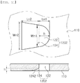
- a blow hole 1202 according to the present embodiment may be distinguished from the above-described embodiment in view of a shape of an expanded portion 124.
- the blow hole 1202 according to the present embodiment may include an expanded portion 124 that becomes wider toward the stern of the hull.
- the expanded portion 124 may have a generally trapezoidal shape as illustrated in FIG. 11 . Therefore, a maximum width Wn2 of the expanded portion 124 may be wider than a maximum width Wn1 of the through-hole 122.
- a length Ln2 of the expanded portion 124 may be generally the same as a length Ln1 of the through-hole 122.
- the blow hole 1202 configured as described above may be advantageous in distributing gas blown out through the through-hole 122 widely in the width direction of the hull.
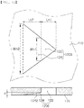
- a blow hole 1204 according to the present embodiment may be distinguished from the above-described embodiment in view of a shape of a through-hole 122.
- the blow hole 1204 according to the present embodiment may include a through-hole 122 having a triangular shape that becomes wider toward the stern of the hull.
- blow hole 1204 may be distinguished from the above-described embodiment in view of a cross-sectional shape of a through-hole 122.
- the through-hole 122 may include a inclined surface 1222 inclined such that gas is blown out in the stern direction.
- the blow hole 1204 configured as described above may be advantageous in blowing out gas in the stern direction and toward the surface of the hull, since the inclined surface 1222 may be formed in the through-hole 122.
- a blow hole 1206 according to the present embodiment may be distinguished from the above-described embodiment in view of a shape of an expanded portion 124.
- the blow hole 1206 according to the present embodiment may include an expanded portion 124 that becomes wider toward the stern of the hull.
- the expanded portion 124 may have a generally trapezoidal shape as illustrated in FIG. 13 . Therefore, a maximum width Wn2 of the expanded portion 124 may be wider than a maximum width Wn1 of the through-hole 122.
- a length Ln2 of the expanded portion 124 may be longer than a length Ln1 of the through-hole 122.
- the expanded portion 124 of the blow hole 1206 may include a curvature.
- a portion of the expanded portion 124 connecting the surface of the hull from the through-hole 122 may be formed as a curved surface 1242 as illustrated in FIG. 13 .
- the blow hole 1206 configured as described above may be advantageous in distributing gas blown out through the through-hole 122 in the width direction of the hull, and in forming an air layer of a predetermined thickness by the gas.
- a blow hole 1202 according to the present embodiment may be distinguished from the above-described embodiment in view of a cross-sectional shape of a through-hole 122.
- the through-hole 122 of the blow hole 1202 may have a smaller cross-sectional area as a distance from a first air storage chamber 110 increases.
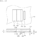
- the blow hole 1202 according to the present embodiment may be distinguished from the above-described embodiment in that the structure 126 may be disposed at an interval from the inlet of the blow hole 1202.
- blow hole 1202 formed as described above is close to a nozzle shape, a large amount of bubbles may be blown out farther to the rear portion of the hull.
- the blow holes 1204 according to the present embodiment may be distinguished from the above-described embodiments in view of a form of structures 126 and 128.
- a plurality of structures 126 and 128 may be formed in a peripheral potion of the blow hole 1204.
- the structures 126 and 128 may have different sizes or heights from each other. For example, a height hp1 of the first structure 126 may be higher than a height hp2 of the second structure 128.
- blow holes 1204 formed as described above are advantageous in view of the fact that seawater in a peripheral potion of the hull 12 may be guided to an external side of the air layer (or bubble layer) more effectively through the plurality of structures 126 and 128.
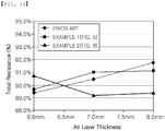
- the prior art exhibited a relatively low total resistance value (89.4%), when a 6 mm thick air layer (or bubble layer) was formed, as illustrated in FIG. 16 .
- the total resistance value increases when a thickness of an air layer increases with the increase of a ship's operating speed (or the increase of an amount of gas to be blown out).
- a conventional ship exhibited a total resistance of 91.7%, when an 8 mm thick air layer was formed.
- a ship having the air storage chamber illustrated in FIG. 6 exhibited a total resistance value (89.7%) similar to that of the prior art, when a 6 mm thick air layer is formed as illustrated in FIG. 16 , and exhibited the stable total resistance value even when a thickness of an air layer was increased with the increase of a ship's operating speed (or the increase of an amount of gas to be blown out).
- the ship according to the present embodiment exhibited a constant total resistance value of 91.1%, even when an air layer having a thickness of 7.5 mm or more was formed.
- a ship having the air storage chamber illustrated in FIG. 8 exhibited a relatively high total resistance value (90.7%) when an air layer having a thickness of 6 mm was formed as illustrated in FIG. 16 , but exhibited a relatively low total resistance value when a thickness of an air layer was increased with the increase of a ship's operating speed (or an increase in an amount of gas to be blown out).
- the ship according to the present embodiment exhibited a relatively low total resistance value of 89.4%, when an air layer of 7.0 mm or more was formed.
- Ships 10a and 10b according to the present embodiment may be distinguished from the above-described embodiments in view of the fact that the formers may further include an auxiliary air storage chamber 500.
- the ship 10a may further include an auxiliary air storage chamber 500 disposed between a fourth air storage chamber 400 and a fourth air storage chamber 400.
- the ship 10b may further include an auxiliary air storage chamber 500 disposed between a third air storage chamber 300 and a third air storage chamber 300.
- the auxiliary air storage chamber 500 may be generally disposed to face a first air storage chamber 100.
- an interval G1 between the second air storage chambers 200 may be equal to or greater than a length L1 of the first air storage chamber 100.
- a pipeline structure of a friction reducing device will be described with reference to FIG. 19 .
- a friction reducing device 20 may include air storage chambers 110, 210, and 310, a pipe duct 600 and a connection pipeline 610.
- the configuration of the friction reducing device 20 is not limited to the above-described members.
- the friction reducing device 20 may further include a pump configured to generate air, a tank configured to store the air generated by the pump, and the like.
- the air storage chambers 110, 210, and 310 may be arranged in the longitudinal direction of the hull 12.
- a first air storage chamber 110, a second air storage chamber 210, and a third air storage chamber 310 may be equally spaced in the longitudinal direction of the hull 12.
- the air storage chambers 110, 210, and 310 may be arranged in a symmetrical manner.
- the first air storage chamber 110, the second air storage chamber 210, and the third air storage chamber 310 may be configured as a pair, respectively.
- the air storage chambers 110, 210, and 310 may be arranged in the width direction of the hull 12. For example, each pair of the air storage compartments 110, 210, and 310 may be spaced apart by predetermined intervals in the width of the hull 12.
- the intervals in the width direction of the hull in the air storage chambers 110, 210, and 310 may increase in the stern direction of the hull 12.
- an interval in the width direction of the hull between the first air storage chambers 110 may be shorter than an interval in the width direction of the hull between the second air storage chambers 210.
- an interval in the width direction of the hull between the second air storage chambers 210 may be shorter than an interval in the width direction of the hull between the third air storage chambers 310.
- the friction reducing device 20 may include three pairs of air storage chambers 110, 210, and 310 in FIG. 19 , the air storage chambers 110, 210, and 310 constituting the friction reducing device 20 are not limited to three pairs.
- the friction reducing device 20 may include four or more pairs of air storage chambers.
- the friction reducing device 20 may include a pipe duct 600.
- the pipe duct 600 may be elongated in the longitudinal direction of the hull 12, and may form a flow path for air to be supplied to the air storage chambers 110, 210, and 310.
- the pipe duct 600 may be covered or treated with sealing members such that gaseous air may be smoothly supplied to the air storage chambers 110, 210, and 310.
- the friction reducing device 20 may include a connection pipeline 610.
- the connection pipeline 610 may extend in the width direction of the hull 12, and may connect the pipe duct 600 and the air storage chambers 110, 210, and 310.
- a cross-sectional area of the connection pipeline 610 may be formed to be smaller than a cross-sectional area of the pipe duct 600.
- the pipe duct 600 may be configured to include a facility pipeline 630.
- the pipe duct 600 may have a sufficient size to accommodate the plurality of facility pipelines 630 therein.
- the facility pipeline 630 may include an electric pipeline, a drinking water pipeline, a hot water pipeline, a fuel pipeline, and the like.
- the pipe duct 600 may be configured to form an air flow path.
- a space in the internal space of the pipe duct 600, except for a space occupied by the facility pipeline 630, may be used as the air flow path 660.
- the pipe duct 600 configured as described above may integrally provide a space for the facility pipeline 630 and the air flow path, such that the space occupied by these members in the hull 12 may be minimized.
- the facility pipeline 630 and the air flow path are formed integrally with the pipe duct 600, an operational process required for installation of these members may be shortened.
- reference numeral 120 illustrated in FIG. 20 may be a blow hole configured to blow air out from the air storage chamber 110 to an external side of the hull.
- a pipe duct 600 according to the present embodiment may be distinguished from the above-described embodiment in view of the fact that the former may further include a partitioning member 640.
- the pipe duct 600 may include a facility pipeline 630, and a member capable of spatially dividing an air flow path.
- a partitioning member 640 may be disposed in an internal portion of the pipe duct 600 to divide a space therein, except for a space in which the facility pipeline 630 is installed. Accordingly, most of the space of the pipe duct 600 may be provided as a space for the facility pipeline 630, but a side space in an upper portion thereof may be used as the air flow path 660.
- a ship 20 having the pipe duct 600 of this type may reduce air pollution from the facility pipeline 630.
- Pipe ducts 602 and 604 may be distinguished from the pipe ducts 600 described above in view of the fact that the formers are composed of a plurality of members.
- the pipe duct may include a first pipe duct 602 and a second pipe duct 604.
- the first pipe duct 602 may be configured to accommodate the second pipe duct 604 therein.
- a cross-sectional size of the first pipe duct 602 may be greater than a cross-sectional size of the second pipe duct 604.
- the first pipe duct 602 may receive a facility pipeline 630, or may form an air flow path 660.
- the first pipe duct 602 may be used as a space for forming the air flow path 660 as illustrated in FIG. 22 , or as a space for accommodating the facility pipeline 630 as illustrated in FIG. 23 .
- the second pipe duct 604 may receive the facility pipeline 630 or form an air flow path 660.
- the second pipe duct 604 may accommodate the facility pipeline 630 therein as illustrated in FIG. 22 , or may form an air flow path 660 as illustrated in FIG. 23 .
- the facility pipeline 630 may be easily repaired, and the air flow path 660 may be easily secured.
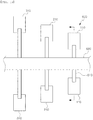
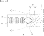
- a side structure of a ship will be described with reference to FIG. 24 .
- a sea chest 70 may be formed in a side portion of the hull 12.
- the sea chest 70 may be connected to a pump disposed in an internal portion of the hull 12. Therefore, when the pump is operated, seawater may be introduced into the internal portion of the hull 12 through the sea chest 70.
- a wire mesh 72 may be disposed at an entrance of the sea chest 70.
- the wire mesh 72 may block marine organisms from entering together with seawater through the sea chest 70 during operation of the pump. Since the wire mesh 72 has a predetermined interval, it may be not possible to reduce a phenomenon in which bubbles generated by the friction reducing device 20 are introduced into the pump in the internal portion of the hull 12.
- a guide member 80 may be disposed in the hull 12 in consideration of the above-described explanations.
- the guide member 80 may be disposed on the bow side of the sea chest 70.
- the guide member 80 may be composed in plural.
- the guide member 80 may include a first guide member 82 and a second guide member 84.
- the guide member 80 may be disposed at a predetermined angle with respect to the longitudinal direction of the hull 12.
- the first guide member 82 may be disposed at a first angle ⁇ 1 with respect to a horizontal axis of the hull 12, and the first guide member 84 may be disposed at a second angle ⁇ 2 with respect to a horizontal axis of the hull 12.
- the first angle ⁇ 1 and the second angle ⁇ 2 may be the same size as each other.
- the first angle ⁇ 1 and the second angle ⁇ 2 are not necessarily formed to have the same size as each other.
- the guide member 80 may be protruded in a predetermined size with respect to the hull 12.
- the guide member 80 arranged as described above may remarkably reduce the phenomenon of bubbles flowing along the surface of the hull 12 into the sea chest 70.
- the guide member 80 may guide the bubbles flowing along the surface of the hull 12 to bypass the same in the longitudinal direction of the guide member 80 and in the vertical direction of the sea chest 70.
- a ship 10 according to the present embodiment may be distinguished from the above-described embodiment in view of the fact that the former may further include a cover member 90.
- a cover member 90 capable of covering the bow side of the sea chest 70 may be disposed on the guide member 80.
- the cover member 90 may be connected to the guide member 80.
- the cover member 90 may have a shape extending from an end portion of the guide member 80 toward the sea chest 70.
- the cover member 90 configured as described above may cover a front portion of the sea chest 70. Therefore, a phenomenon that the bubbles flowing from the bow of the hull 12 in the stern direction are introduced into the sea chest 70 may be reduced.
- a ship 10 according to the present embodiment may be distinguished from the above-described embodiments in view of a form of a cover member 90.
- the cover member 90 may be disposed to cover a lower portion of the sea chest 70.
- the cover member 90 may extend from the hull 12 toward the sea chest 70. In this case, a considerable space may be formed between the cover member 90 and the sea chest 70, such that the inflow of seawater thereinto may be not disturbed.
- the cover member 90 configured as above described may cover the lower portion of the sea chest 70. Therefore, a phenomenon that bubbles flowing from the lower portion of the hull 12 in a water surface direction flows into the sea chest 70 may be effectively reduced.
- a ship 10 may include a means for utilizing seawater.
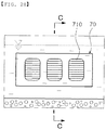
- sea chest 70 may be formed on a side surface of a hull 12.
- the sea chest 70 may be open to an external portion of the hull 12, and may suck and receive seawater from the external portion of the hull 12.
- inlet 710 may be formed in the sea chest 70, as illustrated in FIG. 28 .
- the sea chest 70 may be connected to a mechanical device in an internal portion of the hull 12.
- the sea chest 70 may be connected to a cooling device (not illustrated) of the hull 12.
- the sea chest 70 configured as described above may supply seawater to the cooling device through a pump.
- the sea chest 70 may be connected to another mechanical device of the hull 12.
- the sea chest 70 may be connected to a ballast water treatment device (not illustrated).
- the sea chest 70 configured as described above may supply seawater to a ballast water tank through a pump.
- a sea chest 70 may be formed to store seawater.
- a space for storing seawater may be formed in an internal portion of the sea chest 70.
- the sea chest 70 may be formed to allow inflow of seawater and supply of seawater.
- an inlet 710 and an outlet 720 may be formed in the sea chest 70.
- the inlet 710 may be open to an external portion of the hull 12, such that seawater present in an external portion of the hull 12 may be introduced into an internal portion of the sea chest 70.
- the outlet 720 may be open to an internal portion of the hull 12, such that the seawater stored in the internal portion of the sea chest 70 may be introduced.
- the sea chest 70 may be configured to isolate bubbles contained in seawater.
- a guide member 730 may be formed in an internal portion of the sea chest 70.
- the guide member 730 may extend from an upper portion of the sea chest 70 in a downward direction.
- the guide member 730 may extend from the upper portion of the sea chest 70 to a point lower than the inlet 710.
- a height of a lowermost point of the guide member 730 may be lower than a height of the lowermost point of the inlet 710 by a predetermined height h.
- the guide member 730 may divide an internal space of the sea chest 70 into a plurality of regions.
- the guide member 730 may partition the internal space of the sea chest 70 into a first region 702, a second region 704, and an intermediate region 706.
- the first region 702 may be formed near the inlet 710.
- the first region 702 may be a space extending from the inlet 710 to one surface of the guide member 730.
- the first region 702 formed as described above may be used as a space in which bubbles and the like having a lower specific gravity than seawater are collected.
- the second region 704 may be formed near the outlet 720.
- the second region 704 may be a space extending from the other surface of the guide member 730 to the outlet 720.
- the second region 704 formed as described above may be used as a space in which seawater from which bubbles are removed is stored.
- the intermediate region 706 may be formed in a lower portion of the sea chest 70.
- the intermediate region 706 may be formed near a boundary between the first region 702 and the second region 704.
- the intermediate region 706 formed as described above may be used as a space for preventing from moving bubbles from the first region 702 to the second region 704.
- the sea chest 70 may include a structure that allows a discharge of bubbles.
- an exhaust valve 740 may be formed in the first region 702 of the sea chest 70.
- the exhaust valve 740 may be connected to the atmosphere.
- the exhaust valve 740 may be open up out of the water through a pipeline in an upward direction.
- the exhaust valve 740 configured as described above may enable a discharge of bubbles and gas collected in the first region 702.
- the ship 10 configured as described above may collect and filter the bubbles contained in the seawater flowing into the sea chest 70. Therefore, an occurrence of faults and efficiency deterioration of mechanical devices, that may occur as bubbles are introduced into the pump in an internal portion of the hull, may be significantly reduced.
- the following describes a sea chest having a different structure.
- a sea chest 72 according to the present embodiment may be distinguished from the sea chest 70 of the above-described embodiment in view of a guide member 730.
- the guide member 730 may include a first extended portion 731 and a second extended portion 732.
- the first extended portion 731 may extend generally in a vertical direction of the sea chest 72.
- the first extended portion 731 formed in this manner serves to divide an internal space of the sea chest 72 into a first region 702 and a second region 704, and to block horizontal movement of bubbles.
- the second extended portion 732 may extend generally in a horizontal direction of the sea chest 72.
- the second extended portion 732 may extend in an elongated form from a lowermost end of the first extended portion 731 in a direction opposite to the inlet 710.
- the second extended portion 732 configured as described above may increase a magnitude of an intermediate region 706, which may be a space that may be transferred from the first region 702 to the second region 704, to prevent from moving bubbles from the first region 702 to the second region 704.
- a sea chest 74 according to the present embodiment may be distinguished from the sea chests 70 and 72 of the above-described embodiments in view of a guide member 730.
- the guide member 730 may be composed of a plurality of first guide members 734 and 736, and a second guide member 738.
- the first guide members 734 and 736 may extend from an upper portion of the sea chest 74 in a downward direction.
- the first guide member 734 and the first guide member 736 may be formed at intervals from an inlet 710 in a direction of an outlet 720.
- the plurality of first guide members 734 and 736 arranged in this manner may spatially separate an intermediate region 706 between a first region 702 and a second region 704.
- the second guide member 738 may extend from a lower portion of the sea chest 74 in an upward direction, and may be disposed between the first guide member 734 and the first guide member 736.
- the second guide member 738 arranged as described above may extend a flow path formed in the intermediate region 706, to prevent bubbles from moving from the first region 702 to the second region 704.
- the sea chest 74 may also be distinguished from the sea chests 70 and 72 of the above-described embodiments in view of exhaust valves 740 and 742.
- the exhaust valves 740 and 742 may be formed in the first region 702 and the intermediate region 706, respectively.
- the exhaust valves 740 and 742 arranged as described above may discharge bubbles collected in the first region 702 and the intermediate region 706. Therefore, bubbles contained in seawater may be removed more effectively.
- a sea chest 76 may be formed to allow an inflow of seawater and a supply of seawater.
- an inlet 710 and an outlet 720 may be formed in the sea chest 76.
- the inlet 710 may be open to an external portion of the hull 12 such that seawater present in the external portion of the hull 12 may be introduced into the sea chest 70, and the outlet 720 may be connected to a pipeline 750 extending to an internal portion of the hull 12,
- a ship 10 may include a structure for discharging bubbles and gas introduced into the sea chest 76.
- the ship 10 may include a first valve 760.
- the first valve 760 may be in the form of a trap structure.
- the first valve 760 may be a device having a predetermined space for filtering gas or material having a specific gravity less than seawater, such as bubbles.
- a valve having a trap structure is used for general purpose, a detailed description of the structure of the first valve 760 may be omitted.
- the first valve 760 may be disposed in the pipeline 750.
- the first valve 760 may be disposed at a bended point of the pipeline 750 such that bubbles and gas are easily collected.
- the ship 10 configured as described above may discharge bubbles contained in seawater flowing into the sea chest 76 through the first valve 760. Therefore, failure and efficiency deterioration phenomenon may be remarkably reduced.
- a sea chest according to another embodiment will be described with reference to FIG. 33 .
- a sea chest 77 may be configured to separate bubbles contained in seawater.
- a guide member 730 may be formed in an internal portion of the sea chest 77.
- the guide member 730 may extend from an upper portion of the sea chest 77 in a downward direction.
- the guide member 730 may extend from an upper portion of the sea chest 77 to a point lower than an inlet 710.
- a height of a lowermost point of the guide member 730 may be lower than a height of a lowermost point of the inlet 710 by a predetermined height h.
- the guide member 730 may divide an internal space of the sea chest 77 into a plurality of regions.
- the guide member 730 may partition the internal space of the sea chest 77 into a first region 702, a second region 704, and an intermediate region 706.
- the first region 702 may be formed near the inlet 710.
- the first region 702 may be a space extending from the inlet 710 to one surface of the guide member 730.
- the first region 702 formed as described above may be used as a space in which bubbles and the like having a less specific gravity than seawater are collected.
- the second region 704 may be formed near the outlet 720.
- the second region 704 may be a space extending from the other surface of the guide member 730 to the outlet 720.
- the second region 704 formed as described above may be used as a space in which seawater from which bubbles are removed is stored.
- the intermediate region 706 may be formed in a lower portion of the sea chest 77.
- the intermediate region 706 may be formed near a boundary between the first region 702 and the second region 704.
- the intermediate region 706 formed as described above may be used as a space for preventing from moving bubbles from the first region 702 to the second region 704.
- the sea chest 77 may include a structure that allows a discharge of bubbles.
- a second valve 770 may be formed in the first region 702 of the sea chest 77.
- the second valve 770 may be connected to the atmosphere.
- the second valve 770 may be open, up out of the water, through a pipeline in an upward direction.
- the second valve 770 configured as described above may enable the discharge of bubbles and gas collected in the first region 702.
- a sea chest 78 according to the present embodiment may be distinguished from the sea chests 76 and 77 of the above-described type in view of a guide member 730.
- the guide member 730 may include a first extended portion 731 and a second extended portion 732.
- the first extended portion 731 may extend generally in a vertical direction of the sea chest 78.
- the first extended portion 731 configured as described above serves to divide an internal space of the sea chest 78 into a first region 702 and a second region 704, and to block horizontal movement of the bubbles.
- the second extended portion 732 may extend generally in a horizontal direction of the sea chest 78.
- the second extended portion 732 may extend in an elongated in the direction opposite to the inlet 710 from a lowermost end of the first extended portion 731.
- the second extended portion 732 configured as described above may increase a magnitude of an intermediate region 706, which may be a space that may be transferred from the first region 702 to the second region 704, to prevent from moving bubbles from the first region 702 to the second region 704.
- a sea chest 79 according to the present embodiment may be distinguished from the sea chests 76, 77, and 78 of the above-described embodiments in view of a guide member 730.
- the guide member 730 may be composed of a plurality of first guide members 734 and 736, and a second guide member 738.
- the first guide members 734 and 736 may extend from an upper portion of the sea chest 79 in a downward direction.
- the first guide member 734 and the first guide member 736 may be formed at intervals from an inlet 710 in a direction of an outlet 720.
- the plurality of first guide members 734 and 736 arranged in this manner may spatially separate an intermediate region 706 between a first region 702 and a second region 704.
- the second guide member 738 may extend from a lower portion of the sea chest 79 in an upward direction, and may be disposed between the first guide member 734 and the first guide member 736.
- the second guide member 738 arranged as described above may extend a flow path formed in the intermediate region 706, to prevent from moving bubble from the first region 702 to the second region 704.
- the sea chest 79 may be distinguished from the sea chests 76, 77, and 78 of the above-described embodiments in view of second valves 740 and 742.
- the second valves 770 and 772 may be formed in the first region 702 and the intermediate region 706, respectively.
- the second valves 770 and 772 arranged as described above may discharge bubbles collected in the first region 702 and the intermediate region 706. Therefore, bubbles contained in seawater may be removed more effectively.
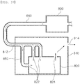
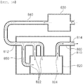
- a ship according to the present embodiment may include a machine room 810, a compressor 820, and a coffer dam 830.
- the components of the ship according to the present embodiment are not limited to the above-described configurations.
- the ship may further include a blower for supplying air of the coffer dam 830 to the machine room 810.
- the ship may further include a device installed in a connection pipeline connected to the machine room to cool the intake air in the coffer dam 830 by a heat exchange principle.
- the ship may further include a valve capable of adjusting an amount of air supplied from the coffer dam 830 to the machine room 810.
- the machine room 810 may be formed in the ship.
- the machine room 810 may be formed in an internal portion of or in the vicinity of the engine room in which an engine of the ship is disposed.
- a position of forming the machine room 810 is not limited to the internal portion of or the vicinity of the engine room.
- An intake port 812 and an outlet 814 may be formed in the machine room 810.
- the intake port 812 may be configured to allow external air to be introduced, and the outlet 814 may be configured to allow air in an internal portion of the machine room 810 to be supplied to the engine room or other necessary place.
- the machine room 810 may be configured to have a significant volume.
- the machine room 810 may be configured to receive one or more compressors 820.
- the machine room 810 may be configured to absorb the impact, or not to be deformed by the impact.
- the machine room 810 may be made of a metal plate having a considerable thickness.
- the machine room 810 configured as described above may protect the compressor 820 from an external impact, and may protect the other mechanical devices of the ship from explosion of the compressor 820 and the like.
- the compressor 820 may be disposed in the machine room 810. Preferably, the compressor 820 may be disposed in a central portion of the machine room 810.
- the compressor 820 may be configured to intake air from the machine room 810.
- an intake port 822 of the compressor 820 may be open to an internal portion of the machine room 810 to intake air filled in the machine room 810.
- the compressor 820 may discharge compressed air through the machine room 810.
- the outlet 824 of the compressor 820 may be configured to face the outlet 814 of the machine room 810, to quickly discharge the compressed air through the outlet 814.
- the coffer dam 830 may be formed in a low temperature tank.
- the coffer dam 830 may be formed near an evaporator of a liquefied gas tank.
- the coffer dam 830 configured as described above may be maintained at a temperature lower than a normal temperature at all times.
- a ship according to the present embodiment may be configured to cool hot air.
- the coffer dam 830 and the machine room 820 may be connected to each other.
- the connection pipeline 840 may be configured such that external air around the coffer dam 830 may be supplied to the intake port 812 of the machine room 810. Therefore, according to the present embodiment, since external air supplied to the machine room 820 may be always lower than a room temperature, the compression efficiency of the compressor 820 may be kept constant even when the ship sails in a tropical region or sails in the hotter summer season.
- FIG. 37 an arrangement of a machine room and a compressor of a ship according to a second embodiment will be described.
- a ship according to the present embodiment may be distinguished from the ship described above in view of the fact that the former may further include a gas-intake pipeline 850.
- the ship according to the present embodiment may further include a gas-intake pipeline 850 for directly connecting an intake port 812 of a machine room 810 and an intake port 822 of a compressor 820.
- a low-temperature air cooled in a coffer dam 830 may be supplied to the compressor 820 without being mixed with air in an internal portion of the machine room 810, the ship configured as above described may be suitable for sailing an extremely high temperature zone.
- a ship according to the embodiment may be distinguished from the above-described ship in view of the fact that the former may further include a gas-exhaust pipeline 860.
- the ship according to the present embodiment may further include the gas-exhaust pipeline 860 for directly connecting an outlet 824 of a compressor 820 and an outlet 814 of a machine room 810.
- Compressed air in the compressor 820 may be supplied to a required point without mixing with air in an internal portion of the machine room 810. Therefore, operation efficiency of a machine using the compressed air may be improved.
- a ship according to the present embodiment may be distinguished from the above-described ship view of the fact that the former may include both a gas-intake pipeline 850 and a gas-exhaust pipeline 860.
- the ship according to the present embodiment may further include the gas-intake pipeline 850 that directly connects an intake port 812 of a machine room 810 and an intake port 822 of a compressor 820, and may further include the gas-exhaust pipeline 860 that directly connects an outlet 824 of the compressor 820 and an outlet 814 of the machine room 810 of the machine room 810.
- the ship configured as described above may exert both the advantages according to the second embodiment and the third embodiment described above.
- a ship according to the present embodiment may include a machine room 810, a compressor 820, and a recovery pipeline 880.
- the components of the ship according to the present embodiment are not limited to the above-described configurations.
- the ship may further include a blower for supplying external air to the machine room 810.
- the machine room 810 may be formed in the ship.
- the machine room 810 may be formed in an internal portion of or in the vicinity of the engine room in which an engine of the ship is disposed.
- a position of forming the machine room 810 is not limited to the internal portion of or the vicinity of the engine room.
- An intake port 812 and an outlet 814 may be formed in the machine room 810.
- the intake port 812 may be configured to allow external air to be introduced, and the outlet 814 may be configured to allow air in an internal portion of the machine room 810 to be supplied to the engine room or other necessary place.
- the machine room 810 may be configured to have a significant volume.
- the machine room 810 may be configured to receive one or more compressors 820.
- the machine room 810 may be configured to absorb the impact, or not to be deformed by the impact.
- the machine room 810 may be made of a metal plate having a considerable thickness.
- the machine room 810 configured as described above may protect the compressor 820 from an external impacts, and may protect the other mechanical devices of the ship from explosions of the compressor 820 and the like.
- the compressor 820 may be disposed in the machine room 810. Preferably, the compressor 820 may be disposed in a central portion of the machine room 810.
- the compressor 820 may be configured to intake air from the machine room 810.
- an intake port 822 of the compressor 820 may be open to an internal portion of the machine room 810 to intake air filling the machine room 810.
- the compressor 820 may discharge compressed air through the machine room 810.
- the outlet 824 of the compressor 820 may be configured to face the outlet 814 of the machine room 810, to quickly discharge the compressed air through the outlet 814.
- the ship according to the present embodiment may be configured to increase a temperature of air introduced into the compressor 810.
- the present embodiment may include a recovery pipeline 880.
- the recovery pipeline 880 may connect the intake port 812 and the outlet 814 of the machine room 810.
- the recovery pipeline 880 may connect an intake pipeline constituting the intake port 812 and a discharge pipeline constituting the outlet 814 such that a high temperature compressed air discharged from the machine room 810 may be re-introduced into the machine room 810. Therefore, according to the present embodiment, since cold air introduced through the intake port 812 is mixed with hot air re-introduced through the recovery pipeline 880, efficiency deterioration of the compressor 820, that may occur as the cold air is introduced into the compressor 820 as it is, may be reduced.
- the ship according to the present embodiment may further include valves 870 and 172.
- a first valve 870 may be disposed at a connection point between the intake port 812 and the recovery pipeline 880, and a second valve 872 may be disposed at a connection point between the outlet 814 and the recovery pipeline 880.
- the first valve 870 and the second valve 872 may be in the form of a three-way valve capable of adjusting a direction of flow at the connection point.
- valves 870 and 172 configured as described above may control an amount of air re-flowing from the recovery pipeline 880 to the intake port 812 and an amount of air re-flowing from the outlet 814 to the recovery pipeline 880. Therefore, efficiency of the compressor 820 may be improved.
- a ship according to the present embodiment may be distinguished from the ship described above in view of the fact that the former may further include a gas-intake pipeline 850.
- the ship according to the present embodiment may further include the gas-intake pipeline 850 for directly connecting an intake port 812 of a machine room 810 and an intake port 822 of a compressor 820.
- a high-temperature air re-introduced by the recovery pipeline may be directly supplied to the compressor 820, without being mixed with the cold air in an internal portion of the machine room 810. Therefore, the ship configured as described above may be suitable for sailing in a region having a very low temperature.
- a ship according to the embodiment may be distinguished from the ship described above in view of the fact that the former may further include a gas-exhaust pipeline 860.
- the ship according to the present embodiment may further include the gas-exhaust pipeline 860 for directly connecting an outlet 824 of a compressor 820 and an outlet 814 of a machine room 810.
- Compressed air in the compressor 820 may be supplied to a required point without mixing with air in an internal portion of the machine room 810. Therefore, operation efficiency of a machine using the compressed air may be improved.
- a ship according to the present embodiment may be distinguished from the ship described above in view of the fact that the former may include both a gas-intake pipeline 850 and a gas-exhaust pipeline 860.
- the ship according to the present embodiment may further include the gas-intake pipeline 850 that directly connects an intake port 812 of a machine room 810 and an intake port 822 of a compressor 820, and may further include the gas-exhaust pipeline 860 that directly connects an outlet 824 of the compressor 820 and an outlet 814 of the machine room 810 of the machine room 810.
- the ships configured as described above may exert all the advantages according to the sixth and seventh embodiments described above.
Landscapes
- Physics & Mathematics (AREA)
- Fluid Mechanics (AREA)
- Chemical & Material Sciences (AREA)
- Engineering & Computer Science (AREA)
- Combustion & Propulsion (AREA)
- Mechanical Engineering (AREA)
- Ocean & Marine Engineering (AREA)
- Filling Or Discharging Of Gas Storage Vessels (AREA)
- Structures Of Non-Positive Displacement Pumps (AREA)
Abstract
Description
- The present disclosure relates to a ship configured to improve operational efficiency, and more particularly, to a ship configured to have significantly reduced frictional resistance between a ship and seawater by using a friction reducing device.
- A ship sailing on the sea may be subject to various types of resistance during operations of the ship. For example, during the operations of the ship, the most of frictional resistance may occur on the wetted surface area of the hull. This frictional resistance may account for about 80% of total resistance in a relatively low speed ship, and about 50% of the total resistance in a relatively high speed ship.
- The frictional resistance occurring on the hull may be due to viscosity of water particles in contact with the hull. Therefore, when a layer of a material less dense than the specific gravity of water is formed between the hull and water to block the viscosity of the water, such frictional resistance may be remarkably reduced. In addition, the reduction of frictional resistance may improve speed of the ship during operations, and may significantly reduce fuel costs of the ship.
- In order to solve the above problem, an air lubrication method in which air is blown from the hull to form a layer of bubbles on a surface of the hull is being studied.
- In the air lubrication method, a method in which air is supplied to an air chamber in a bottom of the ship, air in the air chamber is blown out into water through a plurality of holes passing through an external plate of the bottom of the ship, and the air flows along a surface of the bottom of the ship, has mainly been used.
- Such an air lubrication device may require a separate installation space, and may thus have a problem of obstructing the installation of other devices or increasing a size of a hull.
- Meanwhile, a ship may use seawater to cool mechanical devices such as engines, or the like. For example, a sea chest, configured to receive seawater, may be formed on side surfaces of the ship.
- However, since not only seawater but also bubbles generated by the above-described friction reducing device may be sucked through the sea chest, a problem in which efficiency of a cooling system due to the bubbles is lowered may occur. Therefore, development of a device capable of solving the above problems is required.
- A ship also may include an air compressor. The compressed air generated by the air compressor may be used for starting an engine or a generator engine in the ship. Therefore, performance of the air compressor may influence operational efficiency and facility efficiency of the ship.
- Large ships may sail in various regions. For example, large ships may sail a relatively wide range of regions from tropical regions to polar regions. However, since such conditions for sailing cause deviations in a temperature of air introduced into an air compressor, a problem in which the efficiency of the air compressor is lowered may occur. For example, a ship sailing in tropical waters or sailing during the hotter summer season may have a problem in which relatively high temperature air, having a temperature higher than room temperature, is introduced into the compressor. Meanwhile, a ship sailing in polar waters or sails during the colder winter season may have a problem in which relatively low temperature air, lower than room temperature, is introduced into the compressor.
- Therefore, it is necessary to develop a ship capable of constantly maintaining efficiency of an air compressor, regardless of a region in which a ship is sailing and a season in which a ship is sailing.
- An aspect of the present disclosure is to provide a ship capable of minimizing frictional resistance generated during an operation of the ship.
- Another object of the present disclosure is to provide a ship capable of minimizing an installation space of an air lubrication device.
- Another object of the present disclosure is to provide a ship capable of minimizing re-inflow of gas or bubbles generated by a friction reducing device to the seat chest.
- Another object of the present disclosure is to provide a ship capable of improving efficiency of an air compressor regardless of operating conditions.
- According to an aspect of the present disclosure, a ship may include: a first air storage unit disposed on a bow side of a hull, and including a blow hole configured to blow air out into water; and a plurality of second air storage units disposed closer to a stern end than the first air storage unit, each including a blow hole configured to blow air out into water, and disposed at a first interval in a width direction of the hull, wherein the first interval is shorter than a dimension of the first air storage unit in the width direction.
- The ship according to an aspect of the present disclosure may further include a plurality of third air storage units disposed closer to a stern end than the second air storage unit, each including a blow hole configured to blow air out into water, and disposed at a second interval in the width direction of the hull.
- In the ship according to an aspect of the present disclosure, the second interval may be longer than the first interval.
- In the ship according to an aspect of the present disclosure, the second interval may be shorter than a maximum distance of the second air storage unit in the width direction.
- The ship according to an aspect of the present disclosure may further include a plurality of fourth air storage units disposed closer to a stern end than the third air storage unit, each including a blow hole configured to blow air out into water, and disposed at a third interval in the width direction of the hull.
- In the ship according to an aspect of the present disclosure, the third interval may be greater than the second interval.
- The ship according to an aspect of the present disclosure may further include an auxiliary air storage unit disposed between the plurality of fourth air storage units and including a blow hole configured to blow air out into water.
- The ship according to an aspect of the present disclosure may further include a main pipeline extending in a length direction of the hull.
- The ship according to an aspect of the present disclosure may further include a subsidiary pipeline connected to the main pipeline and connected to the first air storage unit and the second air storage unit, respectively.
- In the ship according to an aspect of the present disclosure, a cross-sectional diameter of the subsidiary pipeline may be shorter than a cross-sectional diameter of the main pipeline.
- The ship according to an aspect of the present disclosure may further include: a first detection sensor configured to measure air pressures of the first air storage unit and the second air storage unit; a first valve configured to adjust an amount of air supplied to the first air storage unit; and a second valve configured to adjust an amount of air supplied to the second air storage unit.
- The ship according to an aspect of the present disclosure may further include: a controller receiving information regarding the air pressure of the first air storage unit and the air pressure of the second air storage unit from the first detection sensor, and controlling opening and closing of the first and second valves, such that deviations between the air pressure of the first air storage unit and the air pressure of the second air storage unit are reduced.
- The ship according to an aspect of the present disclosure may further include a second detection sensor configured to measure roll angle of the hull to transmit the measurement to the controller, wherein the controller is configured to control a magnitude of the opening and closing of the first and second valves to a predetermined magnitude, on the basis of information regarding the roll angle received from the second detection sensor.
- The ship according to an aspect of the present disclosure may further include a second detection sensor configured to measure roll angle of the hull to transmit the measurement to the controller, wherein the controller is configured to control the second valve to adjust an air blowing amount of the second air storage unit disposed on one side of the hull and an air blowing amount of the second air storage unit disposed on the other side of the hull, on the basis of information regarding the roll angle received from the second detection sensor.
- According to an aspect of the present disclosure, frictional resistance generated during an operation of a ship may be minimized to improve operational efficiency of the ship.
- Further, according to an aspect of the present disclosure, an installation space of an air lubrication device may be minimized.
- In addition, according to an aspect of the present disclosure, efficiency deterioration of a cooling system caused by re-inflow of gas or bubbles to the sea chest may be suppressed or reduced.
- Furthermore, according to an aspect of the present disclosure, operational efficiency of an air compressor mounted on a ship sailing in a tropical or polar region may be improved.
-
-
FIG. 1 is a side view of a ship according to an embodiment of the present disclosure; -
FIG. 2 is a bottom view of the ship illustrated inFIG. 1 ; -
FIG. 3 is a schematic diagram of the friction reducing device illustrated inFIG. 1 ; -
FIG. 4 is a perspective view of the air storage unit illustrated inFIG. 3 ; -
FIG. 5 is a bottom perspective view of the first air storage chamber illustrated inFIG. 4 ; -
FIG. 6 is a bottom view of the first air storage chamber illustrated inFIG. 5 ; -
FIG. 7 is an enlarged bottom view and a cross-sectional view of the blow hole illustrated inFIG. 6 ; -
FIG. 8 is a bottom perspective view of an air storage chamber according to another embodiment; -
FIG. 9 is a bottom view of the air storage chamber illustrated inFIG. 8 ; -
FIG. 10 is an enlarged bottom view and a cross-sectional view of the blow hole illustrated inFIG. 9 ; -
FIG. 11 is a bottom view and a cross-sectional view of a blow hole according to another embodiment; -
FIG. 12 is a bottom view and a cross-sectional view of a blow hole according to another embodiment; -
FIG. 13 is a bottom view and a cross-sectional view of a blow hole according to another embodiment; -
FIG. 14 is a bottom view and a cross-sectional view of a blow hole according to another embodiment; -
FIG. 15 is a bottom view and a cross-sectional view of a blow hole according to another embodiment; -
FIG. 16 is a graph illustrating the total resistance value of a ship versus a thickness of an air layer; -
FIG. 17 is a bottom view of a ship according to another embodiment of the present disclosure; -
FIG. 18 is a bottom view of a ship according to another embodiment of the present disclosure; -
FIG. 19 is a schematic diagram of a pipeline of a friction reducing device; -
FIG. 20 is a cross-sectional view taken along line A-A of the pipeline illustrated inFIG. 19 ; -
FIG. 21 is a cross-sectional view taken along line A-A of a pipeline according to another embodiment; -
FIG. 22 is a cross-sectional view taken along line A-A of a pipeline according to another embodiment; -
FIG. 23 is a cross-sectional view taken along line A-A of a pipeline according to another embodiment; -
FIG. 24 is an enlarged side view of the ship illustrated inFIG. 1 ; -
FIG. 25 is an enlarged side view of a ship according to another embodiment; -
FIG. 26 is an enlarged side view of a ship according to another embodiment; -
FIG. 27 is a cross-sectional view taken along line B-B of the ship illustrated inFIG. 26 ; -
FIG. 28 is an enlarged side view of a ship according to another embodiment; -
FIG. 29 is a cross-sectional view taken along line C-C of the sea chest illustrated inFIG. 28 ; -
FIG. 30 is a cross-sectional view taken along line C-C of a sea chest according to another embodiment; -
FIGS. 31 to 35 are cross-sectional views taken along line C-C of a sea chest according to another embodiment; -
FIG. 36 is a layout diagram of a machine room and a compressor of a ship according to a first embodiment of the present disclosure; -
FIG. 37 is a layout diagram of a machine room and a compressor of a ship according to a second embodiment of the present disclosure; -
FIG. 38 is a layout diagram of a machine room and a compressor of a ship according to a third embodiment of the present disclosure; -
FIG. 39 is a layout diagram of a machine room and a compressor of a ship according to a fourth embodiment of the present disclosure; -
FIG. 40 is a layout diagram of a machine room and a compressor of a ship according to a fifth embodiment of the present disclosure; -
FIG. 41 is a layout diagram of a machine room and a compressor of a ship according to a sixth embodiment of the present disclosure; -
FIG. 42 is a layout diagram of a machine room and a compressor of a ship according to a seventh embodiment of the present disclosure; and -
FIG. 43 is a layout diagram of a machine room and a compressor of a ship according to an eighth embodiment of the present disclosure. - Hereinafter, preferred embodiments of the present disclosure will be described in detail with reference to the accompanying drawings.
- In the following description of the present disclosure, the terms referring to the components of the present disclosure are named in consideration of the functions of the respective components, and thus should not be understood as limiting the technical components of the present disclosure.
- In addition, throughout the specification, it can be understood that a configuration may be "connected" with another configuration, including not only when the configurations are directly connected to each other, but also when they are indirectly connected with another configuration. Also, "comprising" means that other components may be included, rather than excluding other components, unless specifically stated otherwise.
- A ship according to an embodiment will be described with reference to
FIG. 1 . - A
ship 10 according to the present embodiment may include means for reducing frictional resistance between ahull 12 and seawater. For example, theship 10 may include afriction reducing device 20. - The
friction reducing device 20 may be disposed in thehull 12. In addition, thefriction reducing device 20 may be disposed on a side of abow 14. Thefriction reducing device 20 disposed as described above may be configured to blow a fluid out, and cover the water from thebow 14 to a stern 16 in thehull 12 by the blown fluid. - The
friction reducing device 20 may be configured to blow gas out. The present disclosure is not limited to the gas, which is to be blown out by thefriction reducing device 20. For example, thefriction reducing device 20 may blow liquid having a specific gravity less than that of water or seawater out. - The
friction reducing device 20 may be configured to blow gas out in a relatively small size. For example, thefriction reducing device 20 may blow gas out in a unit of micrometers. The size of the gas blown out of thefriction reducing device 20 is not limited to a unit of micrometers. For example, thefriction reducing device 20 may blow bubbles out having a size larger than a unit of micrometers or smaller than a unit of micrometers, depending on the size of theship 10. - The
friction reducing device 20 may include a plurality ofair storage units air storage units bow 14 towards the stern 16 of thehull 12. In this case, a distance between theair storage units ship 10. - The
friction reducing device 20 may further include anair compressor 22 and acontroller 24. Theair compressor 22 may be operated to supply a predetermined amount of fluid to theair storage units air compressor 22 may be operated such that a predetermined hydraulic pressure of fluid may be formed in theair storage units controller 24 may be configured to control flow rates of air supplied to theair storage units controller 24 may reduce or increase an amount of gas supplied to at least one of a firstair storage unit 100, a secondair storage unit 200, a thirdair storage unit 300, and a fourthair storage unit 400. - The
ship 10 configured as above described may reduce a contact area and frictional resistance between a surface of thehull 12 and the seawater by thefriction reducing device 20. Therefore, the operational speed may be improved, and the fuel consumption may be reduced. - The
ship 10 may include a means for sensing a rolling condition of thehull 12. For example, asecond detection sensor 50 capable of detecting an inclination of thehull 12 may be disposed on left and right sides of thehull 12. - Next, an arrangement of
air storage units FIG. 2 . - The
air storage units hull 12. In addition, theair storage units hull 12. For example, one of the firstair storage units 100 may be disposed at a front end of thehull 12, two of the secondair storage units 200 may be disposed at a first interval rearward from the firstair storage unit 100, two of the thirdair storage units 300 may be disposed at a second interval, longer than the first interval, rearward from the secondair storage unit 200, and two or more of the fourthair storage units 400 may be disposed at a third interval, longer than the second interval, rearward from the thirdair storage unit 300. Although the arrangement interval of the fourthair storage unit 400 is illustrated to be shorter than a maximum ship width WS of thehull 12, the arrangement interval of the fourthair storage unit 400 should be not always shorter than the maximum ship width WS of thehull 12. - Next, the configuration of the
friction reducing device 20 will be described in detail with reference toFIG. 3 . - The
friction reducing device 20 may include a plurality ofair storage units FIG. 3 . - The
air storage units bow 14 towards a stern 16 of ahull 12. For example, a secondair storage unit 200 may be disposed at a first distance S1 from a firstair storage unit 100, a thirdair storage unit 300 may be disposed at a second distance S2 from the secondair storage unit 200, and a fourthair storage unit 400 may be disposed at a third distance S3 from the thirdair storage unit 300. - The distances S1, S2, and S3 between the different
air storage units - The
air storage units air storage unit 100 may be disposed on abow side 14 of thehull 12, two of the secondair storage units 200 may be disposed at a first interval G1, two of the thirdair storage units 300 may be disposed at a second interval G2, longer than the first interval G1, and two of the fourthair storage units 400 may be disposed at a third interval G3, longer than the second interval G2. - In addition, the
air storage units air storage units air storage units 300 may be disposed to be spaced apart from each other at a second interval G2, longer than a distance (L2 + G1 + L2) from one end of the one secondair storage unit 200 to the other end of the other secondair storage unit 200, and two of the fourthair storage units 400 may be disposed to be spaced apart from each other at a third interval G3, longer than a distance (L3 + G2 + L3) from one end of the one thirdair storage unit 300 to the other end of the other thirdair storage unit 300. - The arrangement of the third
air storage unit 300 and the fourthair storage unit 400 may be advantageous for uniformly forming a large number of bubbles on a surface of thehull 12. - The second
air storage unit 200 may be disposed in a different manner to the thirdair storage unit 300 and the fourthair storage unit 400, in consideration of the fact that frictional resistance may be concentrated in a peripheral portion of a longitudinal center axis of thehull 12. For example, the secondair storage unit 200 may be disposed to partially overlap the firstair storage unit 100. For example, the first interval G1 between the two secondair storage units 200 may be shorter than a length L1 of the firstair storage unit 100. - The
friction reducing device 20 may includepipelines air storage units - A
main pipeline 30 may extend in the longitudinal direction of thehull 12, and may be connected to theair compressor 22. Themain pipeline 30 configured as described above may transfer gas or pressure formed by theair compressor 22 in the longitudinal direction of thehull 12. For reference, in the present embodiment, themain pipeline 30 has a size of several hundred millimeters (approximately 400 millimeters). -
Subsidiary pipelines main pipeline 30 to theair storage units first subsidiary pipeline 32 may connect themain pipeline 30 to the firstair storage unit 100, thesecond subsidiary pipeline 34 may connect themain pipeline 30 to the secondair storage unit 200, thethird subsidiary pipeline 36 may connect themain pipeline 30 to the thirdair storage unit 300, and thefourth subsidiary pipeline 38 may connect themain pipeline 30 to the fourthair storage unit 400. - The
subsidiary pipelines subsidiary pipelines hull 12. In the present embodiment, diameters of thefirst subsidiary pipeline 32 and thesecond subsidiary pipeline 34 may be 150 mm, a diameter of thethird subsidiary pipeline 36 may be 120 mm, and a diameter of thefourth subsidiary pipeline 38 may be 80 mm. - The
friction reducing device 20 may include components for controlling theair storage units friction reducing device 20 may includefirst detection sensors valves - The
first detection sensors air storage units air storage units first detection sensor subsidiary pipeline 30 to thesubsidiary pipelines first detection sensor air storage units - The
first detection sensors air storage units controller 24. - The
valves air storage units first valve 60 may adjust an amount of gas to be supplied to the firstair storage unit 100, thesecond valves 61 and 62 may adjust an amount of gas to be supplied to the secondair storage unit 200, thethird valves 63 and 64 may adjust an amount of gas to be supplied to the thirdair storage unit 300, and thefourth valves air storage unit 400. - The
friction reducing device 20 configured as described above may adjust an amount of bubbles to be blown out of theair storage units ship 10. For example, thefriction reducing device 20 may adjust thevalves air storage units ship 10. On the contrary, thefriction reducing device 20 may adjust thevalves air storage units ship 10. - The
friction reducing device 20 may determine whether theair storage units friction reducing device 20 may determine whether theair storage units first detection sensors first detection sensor 43 is significantly less than a measured value of thefirst detection sensor 44 or a measured value of the otherfirst detection sensor friction reducing device 20 may determine that a blow hole of the thirdair storage unit 300 is blocked by a foreign substance. Thefriction reducing device 20 may close all of theother valves air storage units air storage unit 300. As a comparative embodiment, when a measured value of thefirst detection sensor 40 is significantly less than a measured value of thefirst detection sensor friction reducing device 20 may determine that a blow hole of the firstair storage unit 100 is blocked by a foreign substance, and may close all of thevalves air storage units - Therefore, even when a portion of the
air storage units ship 10 according to the present embodiment may quickly detect and address such a problem. - The
friction reducing device 20 may be configured to control an operation of theair storage units hull 12. For example, thefriction reducing device 20 may determine whether theair storage units hull 12 received from thesecond detection sensor 50. Further, thefriction rescue device 20 may stop an operation of the selected air storage unit, based on the determined information. For example, thefriction reducing device 20 may close thevalves 45 and 46 such that no gas is supplied to the fourthair storage unit 400, when air blown out of the fourthair storage unit 400 by rolling of thehull 12 flows out along a side surface of the ship by buoyancy along the inclined surface formed by a roll motion of the hull, and effects for reducing the frictional resistance are determined as being remarkably decreased. - In the following, the air storage unit will be described with reference to
FIG. 4 . Although only a firstair storage unit 100 is illustrated inFIG. 4 , it can be understood thatair storage units air storage unit 100. - The first
air storage unit 100 may include a plurality ofair storage chambers 110. For example, the firstair storage unit 100 may include fiveair storage chambers 110 as illustrated inFIG. 4 . The number of theair storage chambers 110 constituting the firstair storage unit 100 is not limited to five. For example, the number of theair storage chambers 110 may be increased or decreased, depending on a ship width WS. - The
air storage chamber 110 may have generally rectangular parallelepiped shape. In addition, theair storage chamber 110 has a rectangular parallelepiped shape extending in the width direction of thehull 12. A shape of theair storage chamber 110 is not limited to such a rectangular parallelepiped shape. In one embodiment, the shape of theair storage chamber 110 may be changed to a regular hexahedral or other polyhedral shape, or a cylindrical shape. - The
air storage chamber 110 may be connected to asubsidiary pipeline 32. An internal portion of theair storage chamber 110, connected to thesubsidiary pipeline 32, may be always filled with air having a predetermined pressure. Theair storage chamber 110 configured as described above may continuously blow a large amount of bubbles out into water by pressure applied through thesubsidiary pipeline 32. - The
air storage chamber 110 may be formed integrally with the surface of thehull 12. For example, a bottom surface of theair storage chamber 110 may be in close contact with the surface of thehull 12, or may form a portion of the surface of thehull 12. - A shape of the bottom surface of the first air storage chamber will be described with reference to
FIGS. 5 and 6 . - A plurality of blow holes 120 may be formed in the first
air storage chamber 110. The blow holes 120 may be formed at a predetermined interval St. Theblow hole 120 may be formed in the longitudinal direction of the firstair storage chamber 110. For example, the plurality of blow holes 120 are formed in a single row or a plurality of rows in the longitudinal direction of the firstair storage chamber 110. - The
blow hole 120 formed as described above may be used as a passage through which gas of the firstair storage chamber 110 may be discharged into the water. Meanwhile,FIGS. 5 and 6 illustrate that sevenblow holes 120 are formed in the firstair storage chamber 110, but the number of the blow holes 120 is not limited to seven. For example, the number of the blow holes 120 may vary, depending on the size of the firstair storage chamber 110 and the size of the bubbles to be formed through the blow holes 120. - In the following, a shape of the blow hole will be described with reference to
FIG. 7 . - The
blow hole 120 may be formed to blow gas out of the firstair storage chamber 110 to an external zone of thehull 12. For example, theblow hole 120 may include a through-hole 122 passing through the bottom surface of the firstair storage chamber 110. The through-hole 122 may be formed in a semicircular shape having a predetermined radius r, when viewed in a bottom view. The shape of the through-hole 122 is not limited to such a semicircular shape. For example, the through-hole 122 may be changed to another cross-sectional shape such as a trapezoidal shape or a triangular shape that becomes wider toward the stern of thehull 12. - The
blow hole 120 may be formed to discharge gas of the firstair storage chamber 110 in the stern direction of thehull 120. For example, theblow hole 120 may include an expandedportion 124 having an inclination. The expandedportion 124 may be disposed on the stern side of the through-hole 122, and may be formed to connect the surface of the hull from a certain portion of the through-hole 122. The expandedportion 124 may have generally a rectangular shape elongated in the width direction. For example, a width Wn of the expandedportion 124 may be equal to a diameter (2 x r) of the through-hole 122, and a length Ln of the expandedportion 124 may be equal to a radius r of the through-hole 122. The expandedportion 124 may be formed to be inclined from a point at a predetermined height h of the through-hole 122 in the stern direction as illustrated inFIG. 7 . In this case, a cross-sectional shape of the expandedportion 124 may be a gently curved surface. The cross-sectional shape of the expandedportion 124 is not limited to such a curved surface. For example, a cross-sectional shape of the expandedportion 124 may be changed to a curved surface having a plurality of curvatures, or a stepped shape. - The expanded
portion 124 formed as described above may guide bubbles blown out through the through-hole 122 to move along the surface of thehull 12. For example, the bubbles blown out through theblow hole 120 may form one bubble layer within several millimeters of height from the surface of thehull 12. Therefore, according to the present embodiment, frictional resistance between thehull 12 and seawater may be reduced through the thin bubble layer, such that a power required to operate thefrictional resistance device 20 may be significantly reduced. - Meanwhile, the interval St between the blow holes 120, the radius r of the through-
hole 122, and the width Wn of the expandedportion 124 may be all identical to each other (30 mm in the present embodiment), the height of the expandedportion 124 may be about 1/4 of these magnitudes (8 mm in the present embodiment). The magnitudes of the above configurations are not limited to the above-described numerical values. - Next, another form of the air storage chamber will be described with reference to
FIGS. 8 and 9 . - An
air storage chamber 111 may be modified to have a shape illustrated inFIGS. 8 and 9 . In addition, anair storage chamber 111 according to the present embodiment may be distinguished from the firstair storage chamber 110 of the above-described embodiment in view of a shape of ablow hole 120. For example, theblow hole 120 may include aprotrusion 126. - The blow holes 120 may be disposed on the bottom surface of the
air storage chamber 111 at a predetermined interval St. For example, the plurality of blow holes 120 may be disposed at the same interval as the width of the blow holes 120. For reference, the interval St in the present embodiment may be 30 mm. - The shape of the blow hole will be described in detail with reference to
FIG. 10 . - The
blow hole 120 may be formed to blow air out of theair storage chamber 111 to an external zone of ahull 12. For example, theblow hole 120 may include a through-hole 122 passing through a bottom surface of theair storage chamber 111. The through-hole 122 may have generally a rectangular shape elongated in a width direction, when viewed in a bottom view. The shape of the through-hole 122 is not limited to such a rectangular shape. For example, the through-hole 122 may be changed to another cross-sectional shape such as a trapezoidal shape or a triangular shape that becomes wider toward a stern of thehull 12. - The
blow hole 120 may be formed to discharge gas of theair storage chamber 111 in the stern direction of thehull 120. For example, theblow hole 120 may include an expandedportion 124 having an inclination. The expandedportion 124 may be disposed on the stern side of the through-hole 122, and may be formed to connect the surface of the hull from a certain portion of the through-hole 122. The expandedportion 124 may have a rectangular shape that may be generally the same size as the through-hole 122. For example, a width Wn of the expandedportion 124 may be equal to a width of the through-hole 122, and a length Ln2 of the expandedportion 124 may be equal to a length Ln1 of the through-hole 122 (for reference, the lengths in the present embodiment may be all 30 mm). The expandedportion 124 may be formed to be inclined in the stern direction from a point at a predetermined height (h: 8 mm in the present embodiment) of the through-hole 122 as illustrated inFIG. 9 . In this case, a cross-sectional shape of the expandedportion 124 may be a gently curved surface. The cross-sectional shape of the expandedportion 124 is not limited to such a curved surface. For example, a cross-sectional shape of the expandedportion 124 may be changed to a curved surface having a plurality of curvatures, or a stepped shape. - The
blow hole 120 may be formed to control a thickness of a bubble layer. For example, theblow hole 120 may include aprotrusion 126. Theprotrusion 126 may be disposed on a bow side of the through-hole 122. In addition, theprotrusion 126 may be disposed at a forward end of the through-hole 122, and may protrude from the surface of thehull 12 in a downward direction. - The
protrusions 126 may be generally elongated in the width direction of the through-holes 122. For example, a width of theprotrusion 126 may be generally the same as a width Wn of the through-hole 122. The width of theprotrusion 126 does not necessarily have to be the same as the width Wn of the through-hole 122. For example, the width of theprotrusion 126 may be narrower or wider than the width Wn of the through-hole 122. - The
protrusion 126 may have a cross-sectional shape that becomes thicker from the bow side toward the stern side. In addition, the surface of theprotrusion 126 may be a curved surface having one or more curvatures. The surface of theprotrusion 126 is not limited to such a curved surface. For example, the surface of theprotrusion 126 may be a flat surface having a predetermined inclination angle, or a stepped surface shape. - The
protrusion 126 may have a predetermined height hp. For example, the height of theprotrusion 126 may be lower than the height h of the expandedportion 124. The height of theprotrusion 126 is not limited to the above-mentioned range. For example, the height of theprotrusion 126 may be increased or decreased, depending on the size of theship 10 and the average operating speed. For reference, the height of theprotrusion 126 in the present embodiment may be 3 mm. - The
protrusion 126 formed as described above may change flow of seawater in a peripheral portion of thehull 12, and may prevent bubbles blown out through theblow hole 120 from being irregularly spread or diffused. Therefore, theblow hole 120 according to the present embodiment enables a formation of a thin bubble layer, thereby frictional resistance between thehull 12 and seawater may be effectively reduced. - Referring to
FIG. 11 , a blow hole according to another embodiment will be described. - A
blow hole 1202 according to the present embodiment may be distinguished from the above-described embodiment in view of a shape of an expandedportion 124. In addition, theblow hole 1202 according to the present embodiment may include an expandedportion 124 that becomes wider toward the stern of the hull. For example, the expandedportion 124 may have a generally trapezoidal shape as illustrated inFIG. 11 . Therefore, a maximum width Wn2 of the expandedportion 124 may be wider than a maximum width Wn1 of the through-hole 122. A length Ln2 of the expandedportion 124 may be generally the same as a length Ln1 of the through-hole 122. - The
blow hole 1202 configured as described above may be advantageous in distributing gas blown out through the through-hole 122 widely in the width direction of the hull. - Referring to
FIG. 12 , a blow hole according to another embodiment will be described. - A
blow hole 1204 according to the present embodiment may be distinguished from the above-described embodiment in view of a shape of a through-hole 122. In addition, theblow hole 1204 according to the present embodiment may include a through-hole 122 having a triangular shape that becomes wider toward the stern of the hull. - In addition, the
blow hole 1204 according to the present embodiment may be distinguished from the above-described embodiment in view of a cross-sectional shape of a through-hole 122. In addition, the through-hole 122 may include ainclined surface 1222 inclined such that gas is blown out in the stern direction. - The
blow hole 1204 configured as described above may be advantageous in blowing out gas in the stern direction and toward the surface of the hull, since theinclined surface 1222 may be formed in the through-hole 122. - Referring to
FIG. 13 , a blow hole according to another embodiment will be described. - A
blow hole 1206 according to the present embodiment may be distinguished from the above-described embodiment in view of a shape of an expandedportion 124. In addition, theblow hole 1206 according to the present embodiment may include an expandedportion 124 that becomes wider toward the stern of the hull. For example, the expandedportion 124 may have a generally trapezoidal shape as illustrated inFIG. 13 . Therefore, a maximum width Wn2 of the expandedportion 124 may be wider than a maximum width Wn1 of the through-hole 122. A length Ln2 of the expandedportion 124 may be longer than a length Ln1 of the through-hole 122. - In addition, the expanded
portion 124 of theblow hole 1206 according to the present embodiment may include a curvature. In addition, a portion of the expandedportion 124 connecting the surface of the hull from the through-hole 122 may be formed as acurved surface 1242 as illustrated inFIG. 13 . - The
blow hole 1206 configured as described above may be advantageous in distributing gas blown out through the through-hole 122 in the width direction of the hull, and in forming an air layer of a predetermined thickness by the gas. - Referring to
FIG. 14 , a blow hole according to another embodiment will be described. - A
blow hole 1202 according to the present embodiment may be distinguished from the above-described embodiment in view of a cross-sectional shape of a through-hole 122. In addition, the through-hole 122 of theblow hole 1202 may have a smaller cross-sectional area as a distance from a firstair storage chamber 110 increases. In addition, theblow hole 1202 according to the present embodiment may be distinguished from the above-described embodiment in that thestructure 126 may be disposed at an interval from the inlet of theblow hole 1202. - Since the
blow hole 1202 formed as described above is close to a nozzle shape, a large amount of bubbles may be blown out farther to the rear portion of the hull. - Referring to
FIG. 15 , a blow hole according to another embodiment will be described. - The blow holes 1204 according to the present embodiment may be distinguished from the above-described embodiments in view of a form of
structures structures blow hole 1204. In this case, thestructures first structure 126 may be higher than a height hp2 of thesecond structure 128. - The blow holes 1204 formed as described above are advantageous in view of the fact that seawater in a peripheral potion of the
hull 12 may be guided to an external side of the air layer (or bubble layer) more effectively through the plurality ofstructures - In the following, the total resistance value of the ship according to the embodiments described above with reference to
FIG. 16 will be compared. - The prior art exhibited a relatively low total resistance value (89.4%), when a 6 mm thick air layer (or bubble layer) was formed, as illustrated in
FIG. 16 . However, when a thickness of an air layer increases with the increase of a ship's operating speed (or the increase of an amount of gas to be blown out), the total resistance value also increases. For example, a conventional ship exhibited a total resistance of 91.7%, when an 8 mm thick air layer was formed. - Meanwhile, a ship having the air storage chamber illustrated in
FIG. 6 exhibited a total resistance value (89.7%) similar to that of the prior art, when a 6 mm thick air layer is formed as illustrated inFIG. 16 , and exhibited the stable total resistance value even when a thickness of an air layer was increased with the increase of a ship's operating speed (or the increase of an amount of gas to be blown out). For example, the ship according to the present embodiment exhibited a constant total resistance value of 91.1%, even when an air layer having a thickness of 7.5 mm or more was formed. - In addition, a ship having the air storage chamber illustrated in
FIG. 8 exhibited a relatively high total resistance value (90.7%) when an air layer having a thickness of 6 mm was formed as illustrated inFIG. 16 , but exhibited a relatively low total resistance value when a thickness of an air layer was increased with the increase of a ship's operating speed (or an increase in an amount of gas to be blown out). For example, the ship according to the present embodiment exhibited a relatively low total resistance value of 89.4%, when an air layer of 7.0 mm or more was formed. - Next, a ship according to another embodiment will be described with reference to
FIGS. 17 and18 . -
Ships air storage chamber 500. For example, theship 10a may further include an auxiliaryair storage chamber 500 disposed between a fourthair storage chamber 400 and a fourthair storage chamber 400. In another example, theship 10b may further include an auxiliaryair storage chamber 500 disposed between a thirdair storage chamber 300 and a thirdair storage chamber 300. The auxiliaryair storage chamber 500 may be generally disposed to face a firstair storage chamber 100. - In addition, the
ships air storage chamber 200. For example, an interval G1 between the secondair storage chambers 200 may be equal to or greater than a length L1 of the firstair storage chamber 100. - A pipeline structure of a friction reducing device will be described with reference to
FIG. 19 . - A
friction reducing device 20 may includeair storage chambers pipe duct 600 and aconnection pipeline 610. The configuration of thefriction reducing device 20 is not limited to the above-described members. For example, thefriction reducing device 20 may further include a pump configured to generate air, a tank configured to store the air generated by the pump, and the like. - The
air storage chambers hull 12. For example, a firstair storage chamber 110, a secondair storage chamber 210, and a thirdair storage chamber 310 may be equally spaced in the longitudinal direction of thehull 12. - The
air storage chambers air storage chamber 110, the secondair storage chamber 210, and the thirdair storage chamber 310 may be configured as a pair, respectively. - The
air storage chambers hull 12. For example, each pair of the air storage compartments 110, 210, and 310 may be spaced apart by predetermined intervals in the width of thehull 12. - The intervals in the width direction of the hull in the
air storage chambers hull 12. For example, an interval in the width direction of the hull between the firstair storage chambers 110 may be shorter than an interval in the width direction of the hull between the secondair storage chambers 210. Further, an interval in the width direction of the hull between the secondair storage chambers 210 may be shorter than an interval in the width direction of the hull between the thirdair storage chambers 310. - Although the
friction reducing device 20 may include three pairs ofair storage chambers FIG. 19 , theair storage chambers friction reducing device 20 are not limited to three pairs. For example, thefriction reducing device 20 may include four or more pairs of air storage chambers. - The
friction reducing device 20 may include apipe duct 600. Thepipe duct 600 may be elongated in the longitudinal direction of thehull 12, and may form a flow path for air to be supplied to theair storage chambers pipe duct 600 may be covered or treated with sealing members such that gaseous air may be smoothly supplied to theair storage chambers - The
friction reducing device 20 may include aconnection pipeline 610. Theconnection pipeline 610 may extend in the width direction of thehull 12, and may connect thepipe duct 600 and theair storage chambers connection pipeline 610 may be formed to be smaller than a cross-sectional area of thepipe duct 600. - Next, an internal structure of a pipe duct will be described with reference to
FIG. 20 . - The
pipe duct 600 may be configured to include afacility pipeline 630. For example, thepipe duct 600 may have a sufficient size to accommodate the plurality offacility pipelines 630 therein. For reference, thefacility pipeline 630 may include an electric pipeline, a drinking water pipeline, a hot water pipeline, a fuel pipeline, and the like. - The
pipe duct 600 may be configured to form an air flow path. For example, a space in the internal space of thepipe duct 600, except for a space occupied by thefacility pipeline 630, may be used as theair flow path 660. - The
pipe duct 600 configured as described above may integrally provide a space for thefacility pipeline 630 and the air flow path, such that the space occupied by these members in thehull 12 may be minimized. In addition, according to the present disclosure, since thefacility pipeline 630 and the air flow path are formed integrally with thepipe duct 600, an operational process required for installation of these members may be shortened. - For reference,
reference numeral 120 illustrated inFIG. 20 may be a blow hole configured to blow air out from theair storage chamber 110 to an external side of the hull. - Hereinafter, a mode of a pipe duct according to another embodiment of the present disclosure will be described.
- First, another form of the pipe duct will be described with reference to
FIG. 21 . - A
pipe duct 600 according to the present embodiment may be distinguished from the above-described embodiment in view of the fact that the former may further include apartitioning member 640. - The
pipe duct 600 may include afacility pipeline 630, and a member capable of spatially dividing an air flow path. For example, apartitioning member 640 may be disposed in an internal portion of thepipe duct 600 to divide a space therein, except for a space in which thefacility pipeline 630 is installed. Accordingly, most of the space of thepipe duct 600 may be provided as a space for thefacility pipeline 630, but a side space in an upper portion thereof may be used as theair flow path 660. - A
ship 20 having thepipe duct 600 of this type may reduce air pollution from thefacility pipeline 630. - Next, another form of the pipe duct will be described with reference to
FIGS. 22 and 23 . -
Pipe ducts pipe ducts 600 described above in view of the fact that the formers are composed of a plurality of members. In addition, the pipe duct may include afirst pipe duct 602 and asecond pipe duct 604. - The
first pipe duct 602 may be configured to accommodate thesecond pipe duct 604 therein. For example, a cross-sectional size of thefirst pipe duct 602 may be greater than a cross-sectional size of thesecond pipe duct 604. Thefirst pipe duct 602 may receive afacility pipeline 630, or may form anair flow path 660. For example, thefirst pipe duct 602 may be used as a space for forming theair flow path 660 as illustrated inFIG. 22 , or as a space for accommodating thefacility pipeline 630 as illustrated inFIG. 23 . - The
second pipe duct 604 may receive thefacility pipeline 630 or form anair flow path 660. For example, thesecond pipe duct 604 may accommodate thefacility pipeline 630 therein as illustrated inFIG. 22 , or may form anair flow path 660 as illustrated inFIG. 23 . - Since the
pipe ducts facility pipeline 630 and theair flow path 660, thefacility pipeline 630 may be easily repaired, and theair flow path 660 may be easily secured. - A side structure of a ship will be described with reference to
FIG. 24 . - A
sea chest 70 may be formed in a side portion of thehull 12. Thesea chest 70 may be connected to a pump disposed in an internal portion of thehull 12. Therefore, when the pump is operated, seawater may be introduced into the internal portion of thehull 12 through thesea chest 70. - A
wire mesh 72 may be disposed at an entrance of thesea chest 70. Thewire mesh 72 may block marine organisms from entering together with seawater through thesea chest 70 during operation of the pump. Since thewire mesh 72 has a predetermined interval, it may be not possible to reduce a phenomenon in which bubbles generated by thefriction reducing device 20 are introduced into the pump in the internal portion of thehull 12. In the present embodiment, aguide member 80 may be disposed in thehull 12 in consideration of the above-described explanations. - The
guide member 80 may be disposed on the bow side of thesea chest 70. Theguide member 80 may be composed in plural. For example, theguide member 80 may include afirst guide member 82 and asecond guide member 84. Theguide member 80 may be disposed at a predetermined angle with respect to the longitudinal direction of thehull 12. For example, thefirst guide member 82 may be disposed at a first angle θ1 with respect to a horizontal axis of thehull 12, and thefirst guide member 84 may be disposed at a second angle θ2 with respect to a horizontal axis of thehull 12. In this case, the first angle θ1 and the second angle θ2 may be the same size as each other. The first angle θ1 and the second angle θ2 are not necessarily formed to have the same size as each other. Theguide member 80 may be protruded in a predetermined size with respect to thehull 12. - The
guide member 80 arranged as described above may remarkably reduce the phenomenon of bubbles flowing along the surface of thehull 12 into thesea chest 70. For example, theguide member 80 may guide the bubbles flowing along the surface of thehull 12 to bypass the same in the longitudinal direction of theguide member 80 and in the vertical direction of thesea chest 70. - Therefore, according to the present embodiment, a problem of the efficiency reduction of the pump caused by inflow of bubbles into the pump may be effectively solved.
- Hereinafter, other embodiments of the present disclosure for preventing inflow of bubbles will be described with reference to
FIG. 25 . - A
ship 10 according to the present embodiment may be distinguished from the above-described embodiment in view of the fact that the former may further include acover member 90. In addition, acover member 90 capable of covering the bow side of thesea chest 70 may be disposed on theguide member 80. Thecover member 90 may be connected to theguide member 80. In addition, thecover member 90 may have a shape extending from an end portion of theguide member 80 toward thesea chest 70. - The
cover member 90 configured as described above may cover a front portion of thesea chest 70. Therefore, a phenomenon that the bubbles flowing from the bow of thehull 12 in the stern direction are introduced into thesea chest 70 may be reduced. - Next, referring to
FIGS. 26 and 27 , other aspects of the present disclosure for preventing inflow of bubbles will be described. - A
ship 10 according to the present embodiment may be distinguished from the above-described embodiments in view of a form of acover member 90. In addition, thecover member 90 may be disposed to cover a lower portion of thesea chest 70. For example, thecover member 90 may extend from thehull 12 toward thesea chest 70. In this case, a considerable space may be formed between thecover member 90 and thesea chest 70, such that the inflow of seawater thereinto may be not disturbed. - The
cover member 90 configured as above described may cover the lower portion of thesea chest 70. Therefore, a phenomenon that bubbles flowing from the lower portion of thehull 12 in a water surface direction flows into thesea chest 70 may be effectively reduced. - Next, a description of a sea chest structure of a ship according to another embodiment will be described.
- A
ship 10 may include a means for utilizing seawater. For example, one or more ofsea chest 70 may be formed on a side surface of ahull 12. Thesea chest 70 may be open to an external portion of thehull 12, and may suck and receive seawater from the external portion of thehull 12. To this end, one or more ofinlet 710 may be formed in thesea chest 70, as illustrated inFIG. 28 . - The
sea chest 70 may be connected to a mechanical device in an internal portion of thehull 12. For example, thesea chest 70 may be connected to a cooling device (not illustrated) of thehull 12. Thesea chest 70 configured as described above may supply seawater to the cooling device through a pump. - The
sea chest 70 may be connected to another mechanical device of thehull 12. For example, thesea chest 70 may be connected to a ballast water treatment device (not illustrated). Thesea chest 70 configured as described above may supply seawater to a ballast water tank through a pump. - Next, referring to
FIG. 29 , an internal structure of asea chest 70 will be described. - A
sea chest 70 may be formed to store seawater. For this, a space for storing seawater may be formed in an internal portion of thesea chest 70. Thesea chest 70 may be formed to allow inflow of seawater and supply of seawater. For this, aninlet 710 and anoutlet 720 may be formed in thesea chest 70. Theinlet 710 may be open to an external portion of thehull 12, such that seawater present in an external portion of thehull 12 may be introduced into an internal portion of thesea chest 70. Meanwhile, theoutlet 720 may be open to an internal portion of thehull 12, such that the seawater stored in the internal portion of thesea chest 70 may be introduced. - The
sea chest 70 may be configured to isolate bubbles contained in seawater. For this, aguide member 730 may be formed in an internal portion of thesea chest 70. Theguide member 730 may extend from an upper portion of thesea chest 70 in a downward direction. Preferably, theguide member 730 may extend from the upper portion of thesea chest 70 to a point lower than theinlet 710. For example, a height of a lowermost point of theguide member 730 may be lower than a height of the lowermost point of theinlet 710 by a predetermined height h. - The
guide member 730 may divide an internal space of thesea chest 70 into a plurality of regions. For example, theguide member 730 may partition the internal space of thesea chest 70 into afirst region 702, asecond region 704, and anintermediate region 706. Thefirst region 702 may be formed near theinlet 710. In addition, thefirst region 702 may be a space extending from theinlet 710 to one surface of theguide member 730. Thefirst region 702 formed as described above may be used as a space in which bubbles and the like having a lower specific gravity than seawater are collected. Thesecond region 704 may be formed near theoutlet 720. In addition, thesecond region 704 may be a space extending from the other surface of theguide member 730 to theoutlet 720. Thesecond region 704 formed as described above may be used as a space in which seawater from which bubbles are removed is stored. Theintermediate region 706 may be formed in a lower portion of thesea chest 70. In addition, theintermediate region 706 may be formed near a boundary between thefirst region 702 and thesecond region 704. Theintermediate region 706 formed as described above may be used as a space for preventing from moving bubbles from thefirst region 702 to thesecond region 704. - The
sea chest 70 may include a structure that allows a discharge of bubbles. For example, anexhaust valve 740 may be formed in thefirst region 702 of thesea chest 70. Theexhaust valve 740 may be connected to the atmosphere. For example, theexhaust valve 740 may be open up out of the water through a pipeline in an upward direction. Theexhaust valve 740 configured as described above may enable a discharge of bubbles and gas collected in thefirst region 702. - The
ship 10 configured as described above may collect and filter the bubbles contained in the seawater flowing into thesea chest 70. Therefore, an occurrence of faults and efficiency deterioration of mechanical devices, that may occur as bubbles are introduced into the pump in an internal portion of the hull, may be significantly reduced. - The following describes a sea chest having a different structure.
- First, a sea chest according to another embodiment will be described with reference to
FIG. 30 . - A
sea chest 72 according to the present embodiment may be distinguished from thesea chest 70 of the above-described embodiment in view of aguide member 730. In addition, theguide member 730 may include a firstextended portion 731 and a secondextended portion 732. The firstextended portion 731 may extend generally in a vertical direction of thesea chest 72. The firstextended portion 731 formed in this manner serves to divide an internal space of thesea chest 72 into afirst region 702 and asecond region 704, and to block horizontal movement of bubbles. The secondextended portion 732 may extend generally in a horizontal direction of thesea chest 72. In addition, the secondextended portion 732 may extend in an elongated form from a lowermost end of the firstextended portion 731 in a direction opposite to theinlet 710. The secondextended portion 732 configured as described above may increase a magnitude of anintermediate region 706, which may be a space that may be transferred from thefirst region 702 to thesecond region 704, to prevent from moving bubbles from thefirst region 702 to thesecond region 704. - Next, a sea chest according to another embodiment will be described with reference to
FIG. 31 . - A
sea chest 74 according to the present embodiment may be distinguished from thesea chests guide member 730. In addition, theguide member 730 may be composed of a plurality offirst guide members second guide member 738. - The
first guide members sea chest 74 in a downward direction. Thefirst guide member 734 and thefirst guide member 736 may be formed at intervals from aninlet 710 in a direction of anoutlet 720. The plurality offirst guide members intermediate region 706 between afirst region 702 and asecond region 704. - The
second guide member 738 may extend from a lower portion of thesea chest 74 in an upward direction, and may be disposed between thefirst guide member 734 and thefirst guide member 736. Thesecond guide member 738 arranged as described above may extend a flow path formed in theintermediate region 706, to prevent bubbles from moving from thefirst region 702 to thesecond region 704. - The
sea chest 74 according to the present embodiment may also be distinguished from thesea chests exhaust valves exhaust valves first region 702 and theintermediate region 706, respectively. Theexhaust valves first region 702 and theintermediate region 706. Therefore, bubbles contained in seawater may be removed more effectively. - Next, a description of a sea chest according to another embodiment with reference to
FIG. 32 will be provided. - A
sea chest 76 may be formed to allow an inflow of seawater and a supply of seawater. For this, aninlet 710 and anoutlet 720 may be formed in thesea chest 76. Theinlet 710 may be open to an external portion of thehull 12 such that seawater present in the external portion of thehull 12 may be introduced into thesea chest 70, and theoutlet 720 may be connected to apipeline 750 extending to an internal portion of thehull 12, - A
ship 10 may include a structure for discharging bubbles and gas introduced into thesea chest 76. For example, theship 10 may include afirst valve 760. Thefirst valve 760 may be in the form of a trap structure. For example, thefirst valve 760 may be a device having a predetermined space for filtering gas or material having a specific gravity less than seawater, such as bubbles. For reference, since a valve having a trap structure is used for general purpose, a detailed description of the structure of thefirst valve 760 may be omitted. Thefirst valve 760 may be disposed in thepipeline 750. Preferably, thefirst valve 760 may be disposed at a bended point of thepipeline 750 such that bubbles and gas are easily collected. - The
ship 10 configured as described above may discharge bubbles contained in seawater flowing into thesea chest 76 through thefirst valve 760. Therefore, failure and efficiency deterioration phenomenon may be remarkably reduced. - A sea chest according to another embodiment will be described with reference to
FIG. 33 . - A
sea chest 77 according to the present embodiment may be configured to separate bubbles contained in seawater. For this, aguide member 730 may be formed in an internal portion of thesea chest 77. Theguide member 730 may extend from an upper portion of thesea chest 77 in a downward direction. Preferably, theguide member 730 may extend from an upper portion of thesea chest 77 to a point lower than aninlet 710. For example, a height of a lowermost point of theguide member 730 may be lower than a height of a lowermost point of theinlet 710 by a predetermined height h. - The
guide member 730 may divide an internal space of thesea chest 77 into a plurality of regions. For example, theguide member 730 may partition the internal space of thesea chest 77 into afirst region 702, asecond region 704, and anintermediate region 706. Thefirst region 702 may be formed near theinlet 710. In addition, thefirst region 702 may be a space extending from theinlet 710 to one surface of theguide member 730. Thefirst region 702 formed as described above may be used as a space in which bubbles and the like having a less specific gravity than seawater are collected. Thesecond region 704 may be formed near theoutlet 720. In addition, thesecond region 704 may be a space extending from the other surface of theguide member 730 to theoutlet 720. Thesecond region 704 formed as described above may be used as a space in which seawater from which bubbles are removed is stored. Theintermediate region 706 may be formed in a lower portion of thesea chest 77. In addition, theintermediate region 706 may be formed near a boundary between thefirst region 702 and thesecond region 704. Theintermediate region 706 formed as described above may be used as a space for preventing from moving bubbles from thefirst region 702 to thesecond region 704. - The
sea chest 77 may include a structure that allows a discharge of bubbles. For example, asecond valve 770 may be formed in thefirst region 702 of thesea chest 77. Thesecond valve 770 may be connected to the atmosphere. For example, thesecond valve 770 may be open, up out of the water, through a pipeline in an upward direction. Thesecond valve 770 configured as described above may enable the discharge of bubbles and gas collected in thefirst region 702. - Next, a sea chest according to another embodiment will be described with reference to
FIG. 34 . - A
sea chest 78 according to the present embodiment may be distinguished from thesea chests guide member 730. In addition, theguide member 730 may include a firstextended portion 731 and a secondextended portion 732. The firstextended portion 731 may extend generally in a vertical direction of thesea chest 78. The firstextended portion 731 configured as described above serves to divide an internal space of thesea chest 78 into afirst region 702 and asecond region 704, and to block horizontal movement of the bubbles. The secondextended portion 732 may extend generally in a horizontal direction of thesea chest 78. In addition, the secondextended portion 732 may extend in an elongated in the direction opposite to theinlet 710 from a lowermost end of the firstextended portion 731. The secondextended portion 732 configured as described above may increase a magnitude of anintermediate region 706, which may be a space that may be transferred from thefirst region 702 to thesecond region 704, to prevent from moving bubbles from thefirst region 702 to thesecond region 704. - Next, a sea chest according to another embodiment will be described with reference to
FIG. 35 . - A
sea chest 79 according to the present embodiment may be distinguished from thesea chests guide member 730. In addition, theguide member 730 may be composed of a plurality offirst guide members second guide member 738. - The
first guide members sea chest 79 in a downward direction. Thefirst guide member 734 and thefirst guide member 736 may be formed at intervals from aninlet 710 in a direction of anoutlet 720. The plurality offirst guide members intermediate region 706 between afirst region 702 and asecond region 704. - The
second guide member 738 may extend from a lower portion of thesea chest 79 in an upward direction, and may be disposed between thefirst guide member 734 and thefirst guide member 736. Thesecond guide member 738 arranged as described above may extend a flow path formed in theintermediate region 706, to prevent from moving bubble from thefirst region 702 to thesecond region 704. - The
sea chest 79 according to the present embodiment may be distinguished from thesea chests second valves second valves first region 702 and theintermediate region 706, respectively. Thesecond valves first region 702 and theintermediate region 706. Therefore, bubbles contained in seawater may be removed more effectively. - Next, an arrangement of a machine room and a compressor of a ship according to a first embodiment will be described with reference to
FIG. 36 . - A ship according to the present embodiment may include a
machine room 810, acompressor 820, and acoffer dam 830. The components of the ship according to the present embodiment are not limited to the above-described configurations. For example, the ship may further include a blower for supplying air of thecoffer dam 830 to themachine room 810. The ship may further include a device installed in a connection pipeline connected to the machine room to cool the intake air in thecoffer dam 830 by a heat exchange principle. In addition, the ship may further include a valve capable of adjusting an amount of air supplied from thecoffer dam 830 to themachine room 810. - The
machine room 810 may be formed in the ship. In addition, themachine room 810 may be formed in an internal portion of or in the vicinity of the engine room in which an engine of the ship is disposed. A position of forming themachine room 810 is not limited to the internal portion of or the vicinity of the engine room. Anintake port 812 and anoutlet 814 may be formed in themachine room 810. Theintake port 812 may be configured to allow external air to be introduced, and theoutlet 814 may be configured to allow air in an internal portion of themachine room 810 to be supplied to the engine room or other necessary place. - The
machine room 810 may be configured to have a significant volume. For example, themachine room 810 may be configured to receive one ormore compressors 820. Themachine room 810 may be configured to absorb the impact, or not to be deformed by the impact. For example, themachine room 810 may be made of a metal plate having a considerable thickness. Themachine room 810 configured as described above may protect thecompressor 820 from an external impact, and may protect the other mechanical devices of the ship from explosion of thecompressor 820 and the like. - The
compressor 820 may be disposed in themachine room 810. Preferably, thecompressor 820 may be disposed in a central portion of themachine room 810. Thecompressor 820 may be configured to intake air from themachine room 810. For example, anintake port 822 of thecompressor 820 may be open to an internal portion of themachine room 810 to intake air filled in themachine room 810. Thecompressor 820 may discharge compressed air through themachine room 810. For example, theoutlet 824 of thecompressor 820 may be configured to face theoutlet 814 of themachine room 810, to quickly discharge the compressed air through theoutlet 814. - The
coffer dam 830 may be formed in a low temperature tank. For example, thecoffer dam 830 may be formed near an evaporator of a liquefied gas tank. Thecoffer dam 830 configured as described above may be maintained at a temperature lower than a normal temperature at all times. - A ship according to the present embodiment may be configured to cool hot air. To this end, in the present embodiment, the
coffer dam 830 and themachine room 820 may be connected to each other. For example, theconnection pipeline 840 may be configured such that external air around thecoffer dam 830 may be supplied to theintake port 812 of themachine room 810. Therefore, according to the present embodiment, since external air supplied to themachine room 820 may be always lower than a room temperature, the compression efficiency of thecompressor 820 may be kept constant even when the ship sails in a tropical region or sails in the hotter summer season. - Referring to
FIG. 37 , an arrangement of a machine room and a compressor of a ship according to a second embodiment will be described. - A ship according to the present embodiment may be distinguished from the ship described above in view of the fact that the former may further include a gas-
intake pipeline 850. For example, the ship according to the present embodiment may further include a gas-intake pipeline 850 for directly connecting anintake port 812 of amachine room 810 and anintake port 822 of acompressor 820. - Since a low-temperature air cooled in a
coffer dam 830 may be supplied to thecompressor 820 without being mixed with air in an internal portion of themachine room 810, the ship configured as above described may be suitable for sailing an extremely high temperature zone. - An arrangement of a machine room and a compressor of a ship according to a third embodiment will be described with reference to
FIG. 38 . - A ship according to the embodiment may be distinguished from the above-described ship in view of the fact that the former may further include a gas-
exhaust pipeline 860. For example, the ship according to the present embodiment may further include the gas-exhaust pipeline 860 for directly connecting anoutlet 824 of acompressor 820 and anoutlet 814 of amachine room 810. - Compressed air in the
compressor 820 may be supplied to a required point without mixing with air in an internal portion of themachine room 810. Therefore, operation efficiency of a machine using the compressed air may be improved. - An arrangement of a machine room and a compressor of a ship according to a fourth embodiment will be described with reference to
FIG. 39 . - A ship according to the present embodiment may be distinguished from the above-described ship view of the fact that the former may include both a gas-
intake pipeline 850 and a gas-exhaust pipeline 860. For example, the ship according to the present embodiment may further include the gas-intake pipeline 850 that directly connects anintake port 812 of amachine room 810 and anintake port 822 of acompressor 820, and may further include the gas-exhaust pipeline 860 that directly connects anoutlet 824 of thecompressor 820 and anoutlet 814 of themachine room 810 of themachine room 810. - The ship configured as described above may exert both the advantages according to the second embodiment and the third embodiment described above.
- An arrangement of a machine room and a compressor of a ship according to a fifth embodiment will be described with reference to
FIG. 40 . - A ship according to the present embodiment may include a
machine room 810, acompressor 820, and arecovery pipeline 880. The components of the ship according to the present embodiment are not limited to the above-described configurations. For example, the ship may further include a blower for supplying external air to themachine room 810. - The
machine room 810 may be formed in the ship. In addition, themachine room 810 may be formed in an internal portion of or in the vicinity of the engine room in which an engine of the ship is disposed. A position of forming themachine room 810 is not limited to the internal portion of or the vicinity of the engine room. Anintake port 812 and anoutlet 814 may be formed in themachine room 810. Theintake port 812 may be configured to allow external air to be introduced, and theoutlet 814 may be configured to allow air in an internal portion of themachine room 810 to be supplied to the engine room or other necessary place. - The
machine room 810 may be configured to have a significant volume. For example, themachine room 810 may be configured to receive one ormore compressors 820. Themachine room 810 may be configured to absorb the impact, or not to be deformed by the impact. For example, themachine room 810 may be made of a metal plate having a considerable thickness. Themachine room 810 configured as described above may protect thecompressor 820 from an external impacts, and may protect the other mechanical devices of the ship from explosions of thecompressor 820 and the like. - The
compressor 820 may be disposed in themachine room 810. Preferably, thecompressor 820 may be disposed in a central portion of themachine room 810. Thecompressor 820 may be configured to intake air from themachine room 810. For example, anintake port 822 of thecompressor 820 may be open to an internal portion of themachine room 810 to intake air filling themachine room 810. Thecompressor 820 may discharge compressed air through themachine room 810. For example, theoutlet 824 of thecompressor 820 may be configured to face theoutlet 814 of themachine room 810, to quickly discharge the compressed air through theoutlet 814. - The ship according to the present embodiment may be configured to increase a temperature of air introduced into the
compressor 810. To this end, the present embodiment may include arecovery pipeline 880. - The
recovery pipeline 880 may connect theintake port 812 and theoutlet 814 of themachine room 810. In addition, therecovery pipeline 880 may connect an intake pipeline constituting theintake port 812 and a discharge pipeline constituting theoutlet 814 such that a high temperature compressed air discharged from themachine room 810 may be re-introduced into themachine room 810. Therefore, according to the present embodiment, since cold air introduced through theintake port 812 is mixed with hot air re-introduced through therecovery pipeline 880, efficiency deterioration of thecompressor 820, that may occur as the cold air is introduced into thecompressor 820 as it is, may be reduced. - The ship according to the present embodiment may further include
valves 870 and 172. Afirst valve 870 may be disposed at a connection point between theintake port 812 and therecovery pipeline 880, and asecond valve 872 may be disposed at a connection point between theoutlet 814 and therecovery pipeline 880. Thefirst valve 870 and thesecond valve 872 may be in the form of a three-way valve capable of adjusting a direction of flow at the connection point. - The
valves 870 and 172 configured as described above may control an amount of air re-flowing from therecovery pipeline 880 to theintake port 812 and an amount of air re-flowing from theoutlet 814 to therecovery pipeline 880. Therefore, efficiency of thecompressor 820 may be improved. - An arrangement of a machine room and a compressor of a ship according to a sixth embodiment will be described with reference to
FIG. 41 . - A ship according to the present embodiment may be distinguished from the ship described above in view of the fact that the former may further include a gas-
intake pipeline 850. For example, the ship according to the present embodiment may further include the gas-intake pipeline 850 for directly connecting anintake port 812 of amachine room 810 and anintake port 822 of acompressor 820. - A high-temperature air re-introduced by the recovery pipeline may be directly supplied to the
compressor 820, without being mixed with the cold air in an internal portion of themachine room 810. Therefore, the ship configured as described above may be suitable for sailing in a region having a very low temperature. - An arrangement of a machine room and a compressor of a ship according to a seventh embodiment will be described with reference to
FIG. 42 . - A ship according to the embodiment may be distinguished from the ship described above in view of the fact that the former may further include a gas-
exhaust pipeline 860. For example, the ship according to the present embodiment may further include the gas-exhaust pipeline 860 for directly connecting anoutlet 824 of acompressor 820 and anoutlet 814 of amachine room 810. - Compressed air in the
compressor 820 may be supplied to a required point without mixing with air in an internal portion of themachine room 810. Therefore, operation efficiency of a machine using the compressed air may be improved. - An arrangement of a machine room and a compressor of a ship according to an eighth embodiment will be described with reference to
FIG. 43 . - A ship according to the present embodiment may be distinguished from the ship described above in view of the fact that the former may include both a gas-
intake pipeline 850 and a gas-exhaust pipeline 860. For example, the ship according to the present embodiment may further include the gas-intake pipeline 850 that directly connects anintake port 812 of amachine room 810 and anintake port 822 of acompressor 820, and may further include the gas-exhaust pipeline 860 that directly connects anoutlet 824 of thecompressor 820 and anoutlet 814 of themachine room 810 of themachine room 810. - The ships configured as described above may exert all the advantages according to the sixth and seventh embodiments described above.
- It will be apparent to those skilled in the art that various modifications and variations may be made in the present disclosure without departing from the spirit or scope of the inventions. For example, various features described in the foregoing embodiments may be applied in combination with other embodiments unless the description to the contrary is explicitly stated.
- While exemplary embodiments have been illustrated and described above, it will be apparent to those skilled in the art that modifications and variations could be made without departing from the scope of the present disclosure as defined by the appended claims.
Claims (32)
- A friction reducing device comprising:a first air storage unit including a blow hole configured to blow air out into water; anda plurality of second air storage units disposed rearward from the first air storage unit, each including a blow hole configured to blow air out into water, and disposed at a first interval,wherein the first interval is shorter than a dimension in a width direction of the first air storage unit.
- The friction reducing device according to claim 1, further comprising a plurality of third air storage units disposed rearward from the second air storage unit, each including a blow hole configured to blow air out into water, and disposed at a second interval.
- The friction reducing device according to claim 2, wherein the second interval is longer than the first interval.
- The friction reducing device according to claim 2, further comprising a plurality of fourth air storage units disposed rearward from the third air storage unit, each including a blow hole configured to blow air out into water, and disposed at a third interval.
- The friction reducing device according to claim 4, wherein the third interval is longer than the second interval.
- The friction reducing device according to claim 4, further comprising an auxiliary air storage unit disposed between the plurality of fourth air storage units and including a blow hole configured to blow air out into water.
- The friction reducing device according to claim 1, further comprising:a main pipeline connected to the first air storage unit and extending in a rear direction; anda subsidiary pipeline connecting the main pipeline and the second air storage unit.
- The friction reducing device according to claim 1, further comprising:a first detection sensor configured to measure air pressures of the first air storage unit and the second air storage unit;a first valve configured to adjust an amount of air supplied to the first air storage unit; anda second valve configured to adjust an amount of air supplied to the second air storage unit.
- The friction reducing device according to claim 8, further comprising a controller receiving information regarding the air pressure of the first air storage unit and the air pressure of the second air storage unit from the first detection sensor, and controlling opening and closing of the first and second valves, such that deviations between the air pressure of the first air storage unit and the air pressure of the second air storage unit are reduced.
- The friction reducing device according to claim 1,
wherein the blow hole comprises
a through-hole formed in the first air storage chamber; and
an expanded portion formed in the first air storage chamber and extending from a surface of the first air storage chamber to a side surface of the through-hole. - A ship comprising the friction reducing device according to any one of claims 1 to 10.
- The ship according to claim 11, wherein the first air storage unit is disposed closer to a bow than the second air storage unit.
- The ship according to claim 11, wherein the plurality of second air storage units are disposed in a width direction of a hull.
- The ship according to claim 11, wherein the through-hole of the blow hole has a shape in which a cross-sectional area becomes larger toward a stern of a hull.
- The ship according to claim 11, further comprising:a pipe duct accommodating a facility pipeline therein and forming a flow path of air supplied to the first air storage unit; anda connection pipeline connecting the second air storage unit and the pipe duct.
- The ship according to claim 11, further comprising:a sea chest connected to a ballast water treatment device and configured to receive seawater; anda guide member disposed on a bow side of the sea chest such that bubbles generated by the friction reducing device are not introduced into the sea chest.
- The ship according to claim 16, wherein the guide member comprises:a first guide member formed to be inclined at a first angle; anda second guide member connected to the first guide member and formed to be inclined at a second angle.
- The ship according to claim 16, further comprising a cover member configured to be formed on one side of the sea chest to cover a portion of the sea chest.
- The ship according to claim 11, further comprising:a sea chest in which an inlet into which seawater is introduced and an outlet from which the introduced seawater is discharged are formed; anda guide member dividing a first region in which the inlet is formed and a second region in which the outlet is formed, such that seawater introduced through the inlet is moved to the outlet via an intermediate region lower than the inlet.
- The ship according to claim 19, wherein a height of a lowermost point of the guide member is formed in a position lower than a height of a lowermost point of the inlet.
- The ship according to claim 19, wherein an exhaust valve is further formed in the first region to discharge bubbles or gas collected in the first region externally.
- The ship according to claim 19, wherein the guide member comprises:a first extended portion extending in a height direction of the sea chest; anda second extended portion extending in a width direction of the sea chest.
- The ship according to claim 19, wherein the guide member comprises:a plurality of first guide members extending from an upper portion of the sea chest in a downward direction; anda second guide member extending from a lower portion of the sea chest in a upward direction and disposed between the first guide members;
- The ship according to claim 11, further comprising:a sea chest storing seawater introduced through an inlet;a connection pipeline connecting the sea chest and a mechanical device in a hull; anda first valve disposed in the connection pipeline and configured to discharge bubbles and gas introduced into the sea chest.
- The ship according to claim 11, further comprising:a compressor disposed in a machine room of a hull; anda connection pipeline connecting a coffer dam and the machine room such that air cooled by the coffer dam is introduced into the machine room.
- The ship according to claim 25, wherein the coffer dam is formed in a liquefied gas tank.
- The ship according to claim 25, further comprising a gas-intake pipeline connecting an intake port of the machine room and an intake port of the compressor.
- The ship according to claim 25, further comprising a gas-exhaust pipeline connecting an outlet of the machine room and an outlet of the compressor.
- The ship according to claim 25, wherein the machine room is disposed adjacent to the coffer dam.
- The ship according to claim 11, further comprising:a machine room in which an intake port receiving external air and an outlet discharging compressed air are formed;a compressor disposed in the machine room; anda recovery pipeline connecting the intake port of the machine room and the outlet of the machine room such that air compressed by the compressor is re-introduced into the intake port.
- The ship according to claim 30, further comprising a first valve disposed at a connection point between the recovery pipeline and the intake port, and configured to adjust a ratio of air re-introduced through the recovery pipeline and air newly introduced through the intake port.
- The ship according to claim 30, further comprising a second valve disposed at a connection point between the recovery pipeline and the outlet, and configured to adjust a ratio of air discharged through the outlet and air to be recovered through the recovery pipeline.
Applications Claiming Priority (10)
| Application Number | Priority Date | Filing Date | Title |
|---|---|---|---|
| KR1020160091688A KR102208177B1 (en) | 2016-07-19 | 2016-07-19 | Ship |
| KR1020160091679A KR20180009660A (en) | 2016-07-19 | 2016-07-19 | Ship |
| KR1020160091620A KR20180009636A (en) | 2016-07-19 | 2016-07-19 | Ship |
| KR1020160091659A KR102111306B1 (en) | 2016-07-19 | 2016-07-19 | Ship |
| KR1020160091683A KR102073246B1 (en) | 2016-07-19 | 2016-07-19 | Ship |
| KR1020160091686A KR20180009666A (en) | 2016-07-19 | 2016-07-19 | Ship |
| KR1020160091652A KR102073245B1 (en) | 2016-07-19 | 2016-07-19 | Ship |
| KR1020160091684A KR20180009664A (en) | 2016-07-19 | 2016-07-19 | Ship |
| KR1020160091637A KR20180009642A (en) | 2016-07-19 | 2016-07-19 | Ship |
| PCT/KR2017/007754 WO2018016863A1 (en) | 2016-07-19 | 2017-07-19 | Friction reducing device and ship comprising same |
Publications (4)
| Publication Number | Publication Date |
|---|---|
| EP3489124A1 true EP3489124A1 (en) | 2019-05-29 |
| EP3489124A4 EP3489124A4 (en) | 2019-07-03 |
| EP3489124B1 EP3489124B1 (en) | 2024-06-19 |
| EP3489124C0 EP3489124C0 (en) | 2024-06-19 |
Family
ID=60992232
Family Applications (1)
| Application Number | Title | Priority Date | Filing Date |
|---|---|---|---|
| EP17831336.7A Active EP3489124B1 (en) | 2016-07-19 | 2017-07-19 | Friction reducing device and ship comprising same |
Country Status (3)
| Country | Link |
|---|---|
| EP (1) | EP3489124B1 (en) |
| CN (1) | CN109476360B (en) |
| WO (1) | WO2018016863A1 (en) |
Cited By (3)
| Publication number | Priority date | Publication date | Assignee | Title |
|---|---|---|---|---|
| CN113525586A (en) * | 2020-04-20 | 2021-10-22 | 大宇造船海洋株式会社 | Air Lubrication System for Ships |
| WO2022064025A1 (en) * | 2020-09-28 | 2022-03-31 | Maersk A/S | An air supply system for a hull of a vessel and a vessel comprising the air supply system |
| JP2025081577A (en) * | 2020-11-23 | 2025-05-27 | ヒュンダイ ヘビー インダストリーズ カンパニー リミテッド | Vessel |
Families Citing this family (3)
| Publication number | Priority date | Publication date | Assignee | Title |
|---|---|---|---|---|
| KR20210132860A (en) * | 2020-04-28 | 2021-11-05 | 대우조선해양 주식회사 | Air lubrication system of a ship having high volume fraction of air in a center portion of the ship and air lubrication method using thereof |
| CN114435534A (en) * | 2020-10-30 | 2022-05-06 | 上海斯达瑞船舶海洋工程服务有限公司 | Bubble lubrication drag reduction system and ship |
| CN116022279A (en) * | 2023-01-03 | 2023-04-28 | 广船国际有限公司 | Polar energy-saving container ship |
Family Cites Families (22)
| Publication number | Priority date | Publication date | Assignee | Title |
|---|---|---|---|---|
| JP2001055189A (en) * | 1999-06-08 | 2001-02-27 | Ishikawajima Harima Heavy Ind Co Ltd | Method of reducing frictional resistance of hull and ship with reduced frictional resistance |
| US6789491B2 (en) * | 2000-04-03 | 2004-09-14 | Ishikawajima-Harima Heavy Industries Co., Ltd. | Friction reducing ship and method for reducing frictional resistance |
| JP2002321685A (en) * | 2001-04-27 | 2002-11-05 | Mitsubishi Heavy Ind Ltd | Sea chest |
| PT1501719E (en) * | 2002-05-07 | 2008-07-11 | Dk Group N A N V | Air cavity vessel with wedge-shaped cavities, longitudinally offset cavities, and roll control means and method for constructing the same |
| JP5046102B2 (en) * | 2007-08-09 | 2012-10-10 | 独立行政法人海上技術安全研究所 | Air bubble suction prevention water intake device |
| NZ568155A (en) * | 2008-05-09 | 2009-12-24 | Zuei Ling Lin | Method of reducing frictional resistance between ship body and water by releasing gases in water |
| JP4959668B2 (en) * | 2008-11-21 | 2012-06-27 | 三菱重工業株式会社 | Hull frictional resistance reduction device |
| JP5022344B2 (en) * | 2008-11-21 | 2012-09-12 | 三菱重工業株式会社 | Hull frictional resistance reduction device |
| CN101870331A (en) * | 2009-04-27 | 2010-10-27 | 王昌贵 | High-speed energy-saving air bound warship |
| CN101992836A (en) * | 2009-08-17 | 2011-03-30 | 傅德俐 | Airflow channel bottom floating ship body |
| JP5493122B2 (en) * | 2009-09-18 | 2014-05-14 | 独立行政法人海上技術安全研究所 | Fluid resistance reduction device |
| JP4503688B1 (en) * | 2009-10-05 | 2010-07-14 | 正明 佐藤 | Friction resistance reduction device for ships |
| JP5606128B2 (en) * | 2010-04-01 | 2014-10-15 | 三菱重工業株式会社 | Ship bubble recovery device |
| DK201070283A (en) * | 2010-06-22 | 2012-02-02 | Maersk Olie & Gas | Reducing drag of a hull of a ship |
| JP5797418B2 (en) * | 2011-02-15 | 2015-10-21 | 国立研究開発法人海上技術安全研究所 | Bubble blowing device for reducing frictional resistance of ships |
| WO2012135718A1 (en) * | 2011-03-30 | 2012-10-04 | Juliet Marine Systems, Inc. | High speed surface craft and submersible vehicle |
| JP2012224108A (en) * | 2011-04-15 | 2012-11-15 | Mitsubishi Heavy Ind Ltd | Frictional resistance reduction type ship |
| CH705199A2 (en) * | 2011-06-20 | 2012-12-31 | Marco Feusi | Method of reducing the bow wave resistance of a ship uses apparatus for generating a mixture of gas and water in front of the bow |
| JP5804938B2 (en) * | 2011-12-27 | 2015-11-04 | 三菱重工業株式会社 | Ship resistance reduction device |
| JP2014012443A (en) * | 2012-07-04 | 2014-01-23 | Japan Marine United Corp | Frictional resistance reducing ship |
| KR101810696B1 (en) * | 2012-07-06 | 2018-01-26 | 현대중공업 주식회사 | A ship |
| CN103879510A (en) * | 2014-04-04 | 2014-06-25 | 浙江海洋学院 | Novel energy-saving ship model |
-
2017
- 2017-07-19 WO PCT/KR2017/007754 patent/WO2018016863A1/en not_active Ceased
- 2017-07-19 CN CN201780043673.7A patent/CN109476360B/en active Active
- 2017-07-19 EP EP17831336.7A patent/EP3489124B1/en active Active
Cited By (3)
| Publication number | Priority date | Publication date | Assignee | Title |
|---|---|---|---|---|
| CN113525586A (en) * | 2020-04-20 | 2021-10-22 | 大宇造船海洋株式会社 | Air Lubrication System for Ships |
| WO2022064025A1 (en) * | 2020-09-28 | 2022-03-31 | Maersk A/S | An air supply system for a hull of a vessel and a vessel comprising the air supply system |
| JP2025081577A (en) * | 2020-11-23 | 2025-05-27 | ヒュンダイ ヘビー インダストリーズ カンパニー リミテッド | Vessel |
Also Published As
| Publication number | Publication date |
|---|---|
| WO2018016863A1 (en) | 2018-01-25 |
| EP3489124B1 (en) | 2024-06-19 |
| CN109476360B (en) | 2021-12-17 |
| CN109476360A (en) | 2019-03-15 |
| EP3489124C0 (en) | 2024-06-19 |
| EP3489124A4 (en) | 2019-07-03 |
Similar Documents
| Publication | Publication Date | Title |
|---|---|---|
| EP3489124B1 (en) | Friction reducing device and ship comprising same | |
| US8402930B1 (en) | Method for cooling a four stroke marine engine with increased segregated heat removal from its exhaust manifold | |
| US20190225304A1 (en) | Dual cavity air lubrication system | |
| KR20180091514A (en) | Cooling system for fresh water and ship having the same | |
| TWI657010B (en) | Fuel oil transfer device | |
| KR20140102857A (en) | Engine coolring apparatus for ship and control method thereof | |
| JP2012117455A (en) | Condensed water storage discharge mechanism of heat exchanger | |
| JP7611616B2 (en) | Air supply system and ship applied to gas layer resistance reduction ship | |
| KR20150130711A (en) | Pipeline system and pressure control method of the same | |
| JP2025081577A (en) | Vessel | |
| KR20180009636A (en) | Ship | |
| KR102111306B1 (en) | Ship | |
| US20170233052A1 (en) | Forced flow water circulation cooling for barges | |
| CN214420652U (en) | Gas supply system and boats and ships suitable for gas layer drag reduction boats and ships | |
| KR102208177B1 (en) | Ship | |
| KR20180009660A (en) | Ship | |
| JP6410325B2 (en) | Fuel oil transfer device | |
| EP2957735B1 (en) | Improved generator set | |
| JP2019085970A (en) | Screw compressor | |
| KR20200047475A (en) | Ship | |
| CN220818028U (en) | Air conditioning system, hydraulic center and water diversion tank with air exhaust and pollution discharge functions | |
| KR101994684B1 (en) | Non-power type ballast tank anti-freezing device | |
| EP3702261A1 (en) | Seawater circulation system for ship | |
| KR20260054406A (en) | Ship | |
| RU2728094C1 (en) | Control method of underwater cooling intensity and underwater cooling intensity control device |
Legal Events
| Date | Code | Title | Description |
|---|---|---|---|
| STAA | Information on the status of an ep patent application or granted ep patent |
Free format text: STATUS: THE INTERNATIONAL PUBLICATION HAS BEEN MADE |
|
| PUAI | Public reference made under article 153(3) epc to a published international application that has entered the european phase |
Free format text: ORIGINAL CODE: 0009012 |
|
| STAA | Information on the status of an ep patent application or granted ep patent |
Free format text: STATUS: REQUEST FOR EXAMINATION WAS MADE |
|
| 17P | Request for examination filed |
Effective date: 20190212 |
|
| AK | Designated contracting states |
Kind code of ref document: A1 Designated state(s): AL AT BE BG CH CY CZ DE DK EE ES FI FR GB GR HR HU IE IS IT LI LT LU LV MC MK MT NL NO PL PT RO RS SE SI SK SM TR |
|
| AX | Request for extension of the european patent |
Extension state: BA ME |
|
| A4 | Supplementary search report drawn up and despatched |
Effective date: 20190531 |
|
| RIC1 | Information provided on ipc code assigned before grant |
Ipc: B63B 1/38 20060101AFI20190524BHEP |
|
| DAV | Request for validation of the european patent (deleted) | ||
| DAX | Request for extension of the european patent (deleted) | ||
| STAA | Information on the status of an ep patent application or granted ep patent |
Free format text: STATUS: EXAMINATION IS IN PROGRESS |
|
| 17Q | First examination report despatched |
Effective date: 20200331 |
|
| GRAP | Despatch of communication of intention to grant a patent |
Free format text: ORIGINAL CODE: EPIDOSNIGR1 |
|
| STAA | Information on the status of an ep patent application or granted ep patent |
Free format text: STATUS: GRANT OF PATENT IS INTENDED |
|
| INTG | Intention to grant announced |
Effective date: 20240207 |
|
| GRAS | Grant fee paid |
Free format text: ORIGINAL CODE: EPIDOSNIGR3 |
|
| GRAA | (expected) grant |
Free format text: ORIGINAL CODE: 0009210 |
|
| STAA | Information on the status of an ep patent application or granted ep patent |
Free format text: STATUS: THE PATENT HAS BEEN GRANTED |
|
| AK | Designated contracting states |
Kind code of ref document: B1 Designated state(s): AL AT BE BG CH CY CZ DE DK EE ES FI FR GB GR HR HU IE IS IT LI LT LU LV MC MK MT NL NO PL PT RO RS SE SI SK SM TR |
|
| REG | Reference to a national code |
Ref country code: GB Ref legal event code: FG4D |
|
| REG | Reference to a national code |
Ref country code: CH Ref legal event code: EP |
|
| REG | Reference to a national code |
Ref country code: DE Ref legal event code: R096 Ref document number: 602017082714 Country of ref document: DE |
|
| U01 | Request for unitary effect filed |
Effective date: 20240715 |
|
| U07 | Unitary effect registered |
Designated state(s): AT BE BG DE DK EE FI FR IT LT LU LV MT NL PT SE SI Effective date: 20240723 |
|
| U20 | Renewal fee for the european patent with unitary effect paid |
Year of fee payment: 8 Effective date: 20240726 |
|
| PG25 | Lapsed in a contracting state [announced via postgrant information from national office to epo] |
Ref country code: HR Free format text: LAPSE BECAUSE OF FAILURE TO SUBMIT A TRANSLATION OF THE DESCRIPTION OR TO PAY THE FEE WITHIN THE PRESCRIBED TIME-LIMIT Effective date: 20240619 |
|
| PG25 | Lapsed in a contracting state [announced via postgrant information from national office to epo] |
Ref country code: GR Free format text: LAPSE BECAUSE OF FAILURE TO SUBMIT A TRANSLATION OF THE DESCRIPTION OR TO PAY THE FEE WITHIN THE PRESCRIBED TIME-LIMIT Effective date: 20240920 |
|
| PG25 | Lapsed in a contracting state [announced via postgrant information from national office to epo] |
Ref country code: NO Free format text: LAPSE BECAUSE OF FAILURE TO SUBMIT A TRANSLATION OF THE DESCRIPTION OR TO PAY THE FEE WITHIN THE PRESCRIBED TIME-LIMIT Effective date: 20240919 Ref country code: HR Free format text: LAPSE BECAUSE OF FAILURE TO SUBMIT A TRANSLATION OF THE DESCRIPTION OR TO PAY THE FEE WITHIN THE PRESCRIBED TIME-LIMIT Effective date: 20240619 Ref country code: GR Free format text: LAPSE BECAUSE OF FAILURE TO SUBMIT A TRANSLATION OF THE DESCRIPTION OR TO PAY THE FEE WITHIN THE PRESCRIBED TIME-LIMIT Effective date: 20240920 Ref country code: RS Free format text: LAPSE BECAUSE OF FAILURE TO SUBMIT A TRANSLATION OF THE DESCRIPTION OR TO PAY THE FEE WITHIN THE PRESCRIBED TIME-LIMIT Effective date: 20240919 |
|
| PG25 | Lapsed in a contracting state [announced via postgrant information from national office to epo] |
Ref country code: PL Free format text: LAPSE BECAUSE OF FAILURE TO SUBMIT A TRANSLATION OF THE DESCRIPTION OR TO PAY THE FEE WITHIN THE PRESCRIBED TIME-LIMIT Effective date: 20240619 |
|
| PG25 | Lapsed in a contracting state [announced via postgrant information from national office to epo] |
Ref country code: IS Free format text: LAPSE BECAUSE OF FAILURE TO SUBMIT A TRANSLATION OF THE DESCRIPTION OR TO PAY THE FEE WITHIN THE PRESCRIBED TIME-LIMIT Effective date: 20241019 |
|
| PG25 | Lapsed in a contracting state [announced via postgrant information from national office to epo] |
Ref country code: CZ Free format text: LAPSE BECAUSE OF FAILURE TO SUBMIT A TRANSLATION OF THE DESCRIPTION OR TO PAY THE FEE WITHIN THE PRESCRIBED TIME-LIMIT Effective date: 20240619 |
|
| PG25 | Lapsed in a contracting state [announced via postgrant information from national office to epo] |
Ref country code: SK Free format text: LAPSE BECAUSE OF FAILURE TO SUBMIT A TRANSLATION OF THE DESCRIPTION OR TO PAY THE FEE WITHIN THE PRESCRIBED TIME-LIMIT Effective date: 20240619 Ref country code: RO Free format text: LAPSE BECAUSE OF FAILURE TO SUBMIT A TRANSLATION OF THE DESCRIPTION OR TO PAY THE FEE WITHIN THE PRESCRIBED TIME-LIMIT Effective date: 20240619 |
|
| PG25 | Lapsed in a contracting state [announced via postgrant information from national office to epo] |
Ref country code: ES Free format text: LAPSE BECAUSE OF FAILURE TO SUBMIT A TRANSLATION OF THE DESCRIPTION OR TO PAY THE FEE WITHIN THE PRESCRIBED TIME-LIMIT Effective date: 20240619 Ref country code: SM Free format text: LAPSE BECAUSE OF FAILURE TO SUBMIT A TRANSLATION OF THE DESCRIPTION OR TO PAY THE FEE WITHIN THE PRESCRIBED TIME-LIMIT Effective date: 20240619 |
|
| PG25 | Lapsed in a contracting state [announced via postgrant information from national office to epo] |
Ref country code: SM Free format text: LAPSE BECAUSE OF FAILURE TO SUBMIT A TRANSLATION OF THE DESCRIPTION OR TO PAY THE FEE WITHIN THE PRESCRIBED TIME-LIMIT Effective date: 20240619 Ref country code: SK Free format text: LAPSE BECAUSE OF FAILURE TO SUBMIT A TRANSLATION OF THE DESCRIPTION OR TO PAY THE FEE WITHIN THE PRESCRIBED TIME-LIMIT Effective date: 20240619 Ref country code: RO Free format text: LAPSE BECAUSE OF FAILURE TO SUBMIT A TRANSLATION OF THE DESCRIPTION OR TO PAY THE FEE WITHIN THE PRESCRIBED TIME-LIMIT Effective date: 20240619 Ref country code: PL Free format text: LAPSE BECAUSE OF FAILURE TO SUBMIT A TRANSLATION OF THE DESCRIPTION OR TO PAY THE FEE WITHIN THE PRESCRIBED TIME-LIMIT Effective date: 20240619 Ref country code: IS Free format text: LAPSE BECAUSE OF FAILURE TO SUBMIT A TRANSLATION OF THE DESCRIPTION OR TO PAY THE FEE WITHIN THE PRESCRIBED TIME-LIMIT Effective date: 20241019 Ref country code: ES Free format text: LAPSE BECAUSE OF FAILURE TO SUBMIT A TRANSLATION OF THE DESCRIPTION OR TO PAY THE FEE WITHIN THE PRESCRIBED TIME-LIMIT Effective date: 20240619 Ref country code: CZ Free format text: LAPSE BECAUSE OF FAILURE TO SUBMIT A TRANSLATION OF THE DESCRIPTION OR TO PAY THE FEE WITHIN THE PRESCRIBED TIME-LIMIT Effective date: 20240619 |
|
| REG | Reference to a national code |
Ref country code: CH Ref legal event code: PL |
|
| PG25 | Lapsed in a contracting state [announced via postgrant information from national office to epo] |
Ref country code: MC Free format text: LAPSE BECAUSE OF FAILURE TO SUBMIT A TRANSLATION OF THE DESCRIPTION OR TO PAY THE FEE WITHIN THE PRESCRIBED TIME-LIMIT Effective date: 20240619 |
|
| PG25 | Lapsed in a contracting state [announced via postgrant information from national office to epo] |
Ref country code: MC Free format text: LAPSE BECAUSE OF FAILURE TO SUBMIT A TRANSLATION OF THE DESCRIPTION OR TO PAY THE FEE WITHIN THE PRESCRIBED TIME-LIMIT Effective date: 20240619 |
|
| PG25 | Lapsed in a contracting state [announced via postgrant information from national office to epo] |
Ref country code: CH Free format text: LAPSE BECAUSE OF NON-PAYMENT OF DUE FEES Effective date: 20240731 |
|
| PLBE | No opposition filed within time limit |
Free format text: ORIGINAL CODE: 0009261 |
|
| STAA | Information on the status of an ep patent application or granted ep patent |
Free format text: STATUS: NO OPPOSITION FILED WITHIN TIME LIMIT |
|
| 26N | No opposition filed |
Effective date: 20250320 |
|
| PGFP | Annual fee paid to national office [announced via postgrant information from national office to epo] |
Ref country code: GB Payment date: 20250624 Year of fee payment: 9 |
|
| PG25 | Lapsed in a contracting state [announced via postgrant information from national office to epo] |
Ref country code: IE Free format text: LAPSE BECAUSE OF NON-PAYMENT OF DUE FEES Effective date: 20240719 |
|
| U20 | Renewal fee for the european patent with unitary effect paid |
Year of fee payment: 9 Effective date: 20250723 |
|
| PG25 | Lapsed in a contracting state [announced via postgrant information from national office to epo] |
Ref country code: CY Free format text: LAPSE BECAUSE OF FAILURE TO SUBMIT A TRANSLATION OF THE DESCRIPTION OR TO PAY THE FEE WITHIN THE PRESCRIBED TIME-LIMIT; INVALID AB INITIO Effective date: 20170719 |
|
| PG25 | Lapsed in a contracting state [announced via postgrant information from national office to epo] |
Ref country code: HU Free format text: LAPSE BECAUSE OF FAILURE TO SUBMIT A TRANSLATION OF THE DESCRIPTION OR TO PAY THE FEE WITHIN THE PRESCRIBED TIME-LIMIT; INVALID AB INITIO Effective date: 20170719 |