EP3488089B1 - Abgasausstossvorrichtung für ein wasserfahrzeug - Google Patents
Abgasausstossvorrichtung für ein wasserfahrzeug Download PDFInfo
- Publication number
- EP3488089B1 EP3488089B1 EP17740740.0A EP17740740A EP3488089B1 EP 3488089 B1 EP3488089 B1 EP 3488089B1 EP 17740740 A EP17740740 A EP 17740740A EP 3488089 B1 EP3488089 B1 EP 3488089B1
- Authority
- EP
- European Patent Office
- Prior art keywords
- pipe
- exhaust gas
- radius
- tube
- diffuser ring
- Prior art date
- Legal status (The legal status is an assumption and is not a legal conclusion. Google has not performed a legal analysis and makes no representation as to the accuracy of the status listed.)
- Active
Links
Images


Classifications
-
- F—MECHANICAL ENGINEERING; LIGHTING; HEATING; WEAPONS; BLASTING
- F01—MACHINES OR ENGINES IN GENERAL; ENGINE PLANTS IN GENERAL; STEAM ENGINES
- F01N—GAS-FLOW SILENCERS OR EXHAUST APPARATUS FOR MACHINES OR ENGINES IN GENERAL; GAS-FLOW SILENCERS OR EXHAUST APPARATUS FOR INTERNAL-COMBUSTION ENGINES
- F01N13/00—Exhaust or silencing apparatus characterised by constructional features
- F01N13/004—Exhaust or silencing apparatus characterised by constructional features specially adapted for marine propulsion, i.e. for receiving simultaneously engine exhaust gases and engine cooling water
-
- F—MECHANICAL ENGINEERING; LIGHTING; HEATING; WEAPONS; BLASTING
- F01—MACHINES OR ENGINES IN GENERAL; ENGINE PLANTS IN GENERAL; STEAM ENGINES
- F01N—GAS-FLOW SILENCERS OR EXHAUST APPARATUS FOR MACHINES OR ENGINES IN GENERAL; GAS-FLOW SILENCERS OR EXHAUST APPARATUS FOR INTERNAL-COMBUSTION ENGINES
- F01N13/00—Exhaust or silencing apparatus characterised by constructional features
- F01N13/08—Other arrangements or adaptations of exhaust conduits
- F01N13/082—Other arrangements or adaptations of exhaust conduits of tailpipe, e.g. with means for mixing air with exhaust for exhaust cooling, dilution or evacuation
-
- F—MECHANICAL ENGINEERING; LIGHTING; HEATING; WEAPONS; BLASTING
- F01—MACHINES OR ENGINES IN GENERAL; ENGINE PLANTS IN GENERAL; STEAM ENGINES
- F01N—GAS-FLOW SILENCERS OR EXHAUST APPARATUS FOR MACHINES OR ENGINES IN GENERAL; GAS-FLOW SILENCERS OR EXHAUST APPARATUS FOR INTERNAL-COMBUSTION ENGINES
- F01N3/00—Exhaust or silencing apparatus having means for purifying, rendering innocuous, or otherwise treating exhaust
- F01N3/02—Exhaust or silencing apparatus having means for purifying, rendering innocuous, or otherwise treating exhaust for cooling, or for removing solid constituents of, exhaust
- F01N3/05—Exhaust or silencing apparatus having means for purifying, rendering innocuous, or otherwise treating exhaust for cooling, or for removing solid constituents of, exhaust by means of air, e.g. by mixing exhaust with air
-
- B—PERFORMING OPERATIONS; TRANSPORTING
- B63—SHIPS OR OTHER WATERBORNE VESSELS; RELATED EQUIPMENT
- B63G—OFFENSIVE OR DEFENSIVE ARRANGEMENTS ON VESSELS; MINE-LAYING; MINE-SWEEPING; SUBMARINES; AIRCRAFT CARRIERS
- B63G13/00—Other offensive or defensive arrangements on vessels; Vessels characterised thereby
- B63G13/02—Camouflage
- B63G2013/025—Camouflage using means for reducing radiation emission of electromagnetic waves, e.g. infrared, into air or water
-
- F—MECHANICAL ENGINEERING; LIGHTING; HEATING; WEAPONS; BLASTING
- F01—MACHINES OR ENGINES IN GENERAL; ENGINE PLANTS IN GENERAL; STEAM ENGINES
- F01N—GAS-FLOW SILENCERS OR EXHAUST APPARATUS FOR MACHINES OR ENGINES IN GENERAL; GAS-FLOW SILENCERS OR EXHAUST APPARATUS FOR INTERNAL-COMBUSTION ENGINES
- F01N2240/00—Combination or association of two or more different exhaust treating devices, or of at least one such device with an auxiliary device, not covered by indexing codes F01N2230/00 or F01N2250/00, one of the devices being
- F01N2240/20—Combination or association of two or more different exhaust treating devices, or of at least one such device with an auxiliary device, not covered by indexing codes F01N2230/00 or F01N2250/00, one of the devices being a flow director or deflector
-
- F—MECHANICAL ENGINEERING; LIGHTING; HEATING; WEAPONS; BLASTING
- F01—MACHINES OR ENGINES IN GENERAL; ENGINE PLANTS IN GENERAL; STEAM ENGINES
- F01N—GAS-FLOW SILENCERS OR EXHAUST APPARATUS FOR MACHINES OR ENGINES IN GENERAL; GAS-FLOW SILENCERS OR EXHAUST APPARATUS FOR INTERNAL-COMBUSTION ENGINES
- F01N2260/00—Exhaust treating devices having provisions not otherwise provided for
- F01N2260/02—Exhaust treating devices having provisions not otherwise provided for for cooling the device
- F01N2260/022—Exhaust treating devices having provisions not otherwise provided for for cooling the device using air
-
- F—MECHANICAL ENGINEERING; LIGHTING; HEATING; WEAPONS; BLASTING
- F01—MACHINES OR ENGINES IN GENERAL; ENGINE PLANTS IN GENERAL; STEAM ENGINES
- F01N—GAS-FLOW SILENCERS OR EXHAUST APPARATUS FOR MACHINES OR ENGINES IN GENERAL; GAS-FLOW SILENCERS OR EXHAUST APPARATUS FOR INTERNAL-COMBUSTION ENGINES
- F01N2270/00—Mixing air with exhaust gases
- F01N2270/02—Mixing air with exhaust gases for cooling exhaust gases or the apparatus
-
- F—MECHANICAL ENGINEERING; LIGHTING; HEATING; WEAPONS; BLASTING
- F01—MACHINES OR ENGINES IN GENERAL; ENGINE PLANTS IN GENERAL; STEAM ENGINES
- F01N—GAS-FLOW SILENCERS OR EXHAUST APPARATUS FOR MACHINES OR ENGINES IN GENERAL; GAS-FLOW SILENCERS OR EXHAUST APPARATUS FOR INTERNAL-COMBUSTION ENGINES
- F01N2270/00—Mixing air with exhaust gases
- F01N2270/08—Mixing air with exhaust gases for evacuation of exhaust gases, e.g. in tail-pipes
-
- F—MECHANICAL ENGINEERING; LIGHTING; HEATING; WEAPONS; BLASTING
- F01—MACHINES OR ENGINES IN GENERAL; ENGINE PLANTS IN GENERAL; STEAM ENGINES
- F01N—GAS-FLOW SILENCERS OR EXHAUST APPARATUS FOR MACHINES OR ENGINES IN GENERAL; GAS-FLOW SILENCERS OR EXHAUST APPARATUS FOR INTERNAL-COMBUSTION ENGINES
- F01N2470/00—Structure or shape of exhaust gas passages, pipes or tubes
- F01N2470/08—Exhaust gas passages being formed between the walls of an outer shell and an inner chamber
-
- F—MECHANICAL ENGINEERING; LIGHTING; HEATING; WEAPONS; BLASTING
- F01—MACHINES OR ENGINES IN GENERAL; ENGINE PLANTS IN GENERAL; STEAM ENGINES
- F01N—GAS-FLOW SILENCERS OR EXHAUST APPARATUS FOR MACHINES OR ENGINES IN GENERAL; GAS-FLOW SILENCERS OR EXHAUST APPARATUS FOR INTERNAL-COMBUSTION ENGINES
- F01N2470/00—Structure or shape of exhaust gas passages, pipes or tubes
- F01N2470/24—Concentric tubes or tubes being concentric to housing, e.g. telescopically assembled
-
- F—MECHANICAL ENGINEERING; LIGHTING; HEATING; WEAPONS; BLASTING
- F01—MACHINES OR ENGINES IN GENERAL; ENGINE PLANTS IN GENERAL; STEAM ENGINES
- F01N—GAS-FLOW SILENCERS OR EXHAUST APPARATUS FOR MACHINES OR ENGINES IN GENERAL; GAS-FLOW SILENCERS OR EXHAUST APPARATUS FOR INTERNAL-COMBUSTION ENGINES
- F01N2470/00—Structure or shape of exhaust gas passages, pipes or tubes
- F01N2470/30—Tubes with restrictions, i.e. venturi or the like, e.g. for sucking air or measuring mass flow
-
- F—MECHANICAL ENGINEERING; LIGHTING; HEATING; WEAPONS; BLASTING
- F01—MACHINES OR ENGINES IN GENERAL; ENGINE PLANTS IN GENERAL; STEAM ENGINES
- F01N—GAS-FLOW SILENCERS OR EXHAUST APPARATUS FOR MACHINES OR ENGINES IN GENERAL; GAS-FLOW SILENCERS OR EXHAUST APPARATUS FOR INTERNAL-COMBUSTION ENGINES
- F01N2590/00—Exhaust or silencing apparatus adapted to particular use, e.g. for military applications, airplanes, submarines
- F01N2590/02—Exhaust or silencing apparatus adapted to particular use, e.g. for military applications, airplanes, submarines for marine vessels or naval applications
-
- Y—GENERAL TAGGING OF NEW TECHNOLOGICAL DEVELOPMENTS; GENERAL TAGGING OF CROSS-SECTIONAL TECHNOLOGIES SPANNING OVER SEVERAL SECTIONS OF THE IPC; TECHNICAL SUBJECTS COVERED BY FORMER USPC CROSS-REFERENCE ART COLLECTIONS [XRACs] AND DIGESTS
- Y02—TECHNOLOGIES OR APPLICATIONS FOR MITIGATION OR ADAPTATION AGAINST CLIMATE CHANGE
- Y02T—CLIMATE CHANGE MITIGATION TECHNOLOGIES RELATED TO TRANSPORTATION
- Y02T10/00—Road transport of goods or passengers
- Y02T10/10—Internal combustion engine [ICE] based vehicles
- Y02T10/12—Improving ICE efficiencies
Definitions
- the invention relates to a device for reducing the heat signature of a vehicle, in particular a watercraft.
- Energy is generated in vehicles, for example watercraft, for example corvettes or frigates, usually by means of internal combustion engines, for example from diesel or gas. It is known that hot exhaust gases are produced during combustion. These exhaust gases are released into the circulating air. This creates warm areas in the air and the environment in which the air escapes also warms up regularly. This makes it very easy to locate the vehicle in the infrared range.
- the object of the invention is to provide a device for a watercraft in which an optimum of flow resistance, cooling of the exhaust gas flow, economy and robustness of the device and thus an efficient reduction of the heat signature is possible.
- the first tube has a circular or elliptical cross section, wherein the radius of the first tube can vary depending on the height.
- a second tube is arranged inside the first tube. The second tube is closed at the bottom.
- the second tube has a circular or elliptical cross section, wherein the radius of the second tube can vary depending on the height.
- the radius of the first tube is larger than the radius of the second tube.
- Ambient air can be conducted through the second pipe.
- a first diffuser ring is arranged above the second tube and inside the first tube.
- the result is that the radius of the first pipe is greater than the radius of the second pipe at a given height.
- the thickness of the first air gap is preferably at least 3%, more preferably at least 8%, particularly preferably at least 15% of the radius of the first tube.
- the thickness of the first air gap is preferably at most 80%, more preferably at least 60%, particularly preferably at least 35% of the radius of the first tube.
- the first diffuser ring has a circular or elliptical cross section.
- the radius of the first diffuser ring is larger on the side adjacent to the second tube than the radius of the second tube (20) on the side adjacent to the first diffuser ring (30). This creates a gap so that the hot exhaust gas not only flows around the outside of the first diffuser ring, but also also reaches the inside of the diffuser ring.
- the diffuser ring is thus exposed to hot exhaust gas on both sides, with the exhaust gas already mixing on the inside with the cold ambient air which is supplied via the second pipe.
- the ambient air that can be conducted through the second pipe is used to cool the exhaust gas flow in the first pipe.
- a diffuser ring is arranged above the second pipe in order to achieve a mixing of the two air streams without achieving great flow resistance.
- the axis of symmetry of the first tube and the axis of symmetry of the second tube coincide.
- the second tube tapers to a point at the lower end.
- the lower end of the second tube is conical.
- the second tube is rounded at the lower end.
- the lower end of the second tube is hemispherical. This shape is also formed in the case of drops, for example, and is particularly streamlined.
- the radius of the first diffuser ring can vary as a function of the height.
- the axis of symmetry of the first diffuser ring and the axis of symmetry of the second tube coincide.
- the shape of the diffuser ring is chosen such that its inner surface runs at least in places parallel to the upper peripheral surface of the second tube. It is particularly preferred that only the lower circumferential surface of the diffuser ring is parallel to the upper circumferential surface of the second tube.
- the radius of the first diffuser ring increases from bottom to top.
- the increase in the radius creates an outwardly curved shape of the diffuser ring, similar in cross-section to a wing surface. This increases the mixing effect through the diffuser ring.
- the surface of the diffuser ring is preferably curved outwards.
- the curvature of the inner surface and the outer surface can particularly preferably be approximated by quadratic functions, the functions being different from one another.
- the first tube can be curved inward for reinforcement, which leads to a further increase in pressure in the outer area between the first tube and the diffuser ring.
- an outer ring-shaped gas flow forms on the wall side, which is particularly accelerated.
- an effect is produced which is similar to that of a water jet pump and leads to efficient mixing by entrainment of the ambient air surrounding the first pipe.
- the diffuser ring is rounded at the lower end and has a pointed shape at the upper end.
- the radius of the first tube at a given height is greater than the radius of the diffuser ring.
- the thickness of the second air gap is preferably at least 2%, more preferably at least 5%, particularly preferably at least 10% of the radius of the first tube.
- the thickness of the second air gap is preferably at most 80%, more preferably at least 60%, particularly preferably at least 35% of the radius of the first tube.
- a third tube is arranged above the first tube.
- the third tube has a circular or elliptical cross section, wherein the radius of the third tube can vary depending on the height.
- the radius of the third pipe is larger than the radius of the first pipe.
- the axis of symmetry of the first tube and the axis of symmetry of the third tube coincide.
- the use of a third pipe results in further intermixing between the hot exhaust gas, which is further intermixed and cooled with the cold air coming from the external environment. There is thus a first cooling in the core through the cold air conducted through the second tube and through the cold air supplied from the outside in the third tube.
- a fourth pipe is arranged above the third pipe.
- the fourth tube has a circular or elliptical cross section, wherein the radius of the fourth tube can vary depending on the height.
- the smallest radius of the fourth tube is larger than the largest radius of the third tube, the axis of symmetry of the third tube and the axis of symmetry of the fourth tube coinciding.
- the third tube can be arranged partially within the fourth tube.
- the third tube can also be tapered at the upper end.
- the additional use of a fourth pipe with a larger diameter creates an air gap between the third and fourth pipe through which ambient air is fed into the exhaust gas flow. In a second stage of mixing with cold ambient air, the exhaust gas is cooled further.
- a fifth pipe is also arranged above the fourth pipe and, in an analogous manner, has a larger radius than the fourth pipe. Another air gap is formed through which further mixing can be achieved.
- At least three air inlets are arranged in such a way that they direct air from outside the first tube into the interior of the second tube.
- the air supply can for example be designed in the form of a tube. Through the air supply, cold ambient air can get into the second pipe in order to cool the core of the exhaust gas flow without having been mixed with exhaust gas beforehand. At the same time, a few, for example three air inlets, only represent a low flow resistance.
- the at least three air inlets serve to support the second tube.
- a support is necessary. If the support is taken over by the air supply, further components are omitted, so that there is less flow resistance.
- the air inlets have a teardrop-shaped cross section.
- the drop-shaped cross-section (round and wide at the bottom, tapering to a point at the top) is flow-optimized and also means that the flow of exhaust gas is opposed to the lowest possible flow resistance.
- the at least three air inlets are designed in such a way that the exhaust gas flow flowing through the first pipe passes through the at least three Air inlets is set in rotation.
- the air supply lines have a cross-section deviating from the rotational symmetry.
- the cross section can be shaped like a wing and thus have a suction side and a pressure side.
- the air supplies are advantageously arranged in such a way that the suction side of one air supply is adjacent to the pressure side of another air supply, which results in a circular movement in the exhaust gas flow.
- the exhaust gas ejection device has a delivery device, the delivery device being designed to deliver air through the air supply lines.
- the cold ambient air can also be actively conveyed. This results in a significantly stronger cooling of the exhaust gas flow.
- this also has some disadvantages.
- the additional active amount of gas delivered leads to an increased counter pressure against the exhaust gas.
- costs and wear increase. Therefore, for example, a conveying device can be provided which, however, does not actively convey in regular operation and is only actively switched on in a combat situation in order to achieve a maximum cooling effect in the short term.
- a second diffuser ring is arranged above the first diffuser ring and inside the first tube. If the exhaust gas ejection device has a third pipe, the second diffuser ring is preferably arranged between the first diffuser ring and the third pipe.
- an exhaust gas ejection device with a water injection device in a further embodiment of the invention, an exhaust gas ejection device with a water injection device.
- the water injection can take place in one or more places.
- the advantage of water injection is the extremely efficient cooling, on the one hand through the very high heat capacity of water and on the other hand through the utilization of the likewise comparatively high enthalpy of evaporation.
- the disadvantage is the cost and the constant presence of water in the area. Therefore, water injection is preferably only switched on optionally if intensive cooling, for example in the event of a battle, is essential.
- the invention relates to a watercraft with an exhaust gas ejection device according to the invention, preferably a military watercraft.
- the invention relates to a method for operating an exhaust gas ejection device, the exhaust gas ejection device having a conveying device for conveying air and a water injection device.
- the device can be operated in four basic operating states. In purely passive mode, there is neither active delivery of air nor water injection. In active operation, air is actively conveyed, but no water injection. In intensive operation, air is actively conveyed and water is injected. In humid operation, only water is injected, but no active air delivery.
- the method includes the specification of the operational parameters.
- the operating status that matches the application parameters is selected.
- the simple transfer trip is specified as the application parameter.
- economic considerations are predominant, so passive operation is selected.
- the signature must be kept as small as possible for a long period of time, but the operation must be designed for the longest possible downtime at sea. Active operation is therefore selected for this case.
- the minimization of the signature is absolutely paramount, so that in this case intensive operation is selected.
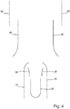
- a first exhaust gas ejection device is shown in cross section.
- the exhaust gas ejection device consists of a first pipe 10 into which hot exhaust gas is introduced from below and from which exhaust gas cooled above is ejected.
- a second tube 20 is arranged in the first tube 10. This is closed at the bottom and open at the top. Cold air is entrained from the second pipe 20 by the gas flow of the warm exhaust gas. Alternatively or additionally, cold air can also be actively conveyed from the second pipe 20.
- a first diffuser ring 30 is arranged above the second tube 20.
- Fig. 2 Fig. 10 shows a second exhaust gas ejector which is comparable to the first exhaust gas ejector. The only difference is that the first tube 10 has a constriction at the top in order to increase the flow velocity at the outlet.
- a third exhaust gas ejection device which has a third pipe 40 in addition to the second exhaust gas ejection device.
- the third tube 40 is advantageously widened somewhat on its underside, as shown, in order to additionally suck in more cold ambient air.
- FIG. 4 A fourth exhaust gas ejection device is shown which, in addition to the third exhaust gas ejection device, has a fourth pipe 50, the third pipe 40 being partially arranged within the fourth pipe 50. As a result, cold ambient air is drawn in in a further stage.
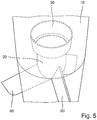
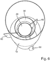
- Fig. 5 Fig. 3 shows a fifth exhaust gas ejector.
- the second pipe 20 is arranged inside the first pipe 10 and is supplied with cold air via three air inlets 60.
- the cold air can flow passively or actively through the air supply lines 60.
- the air inlets 60 carry the second pipe 20 within the first pipe 10.
- the first diffuser ring 30 is arranged above the second pipe 20.
Landscapes
- Engineering & Computer Science (AREA)
- Chemical & Material Sciences (AREA)
- Combustion & Propulsion (AREA)
- Mechanical Engineering (AREA)
- General Engineering & Computer Science (AREA)
- Health & Medical Sciences (AREA)
- Ocean & Marine Engineering (AREA)
- Chemical Kinetics & Catalysis (AREA)
- Toxicology (AREA)
- Exhaust Silencers (AREA)
- Filling Or Discharging Of Gas Storage Vessels (AREA)
- Crystals, And After-Treatments Of Crystals (AREA)
- Sampling And Sample Adjustment (AREA)
Priority Applications (1)
| Application Number | Priority Date | Filing Date | Title |
|---|---|---|---|
| PL17740740T PL3488089T3 (pl) | 2016-07-21 | 2017-07-18 | Urządzenie do wyrzucania spalin dla jednostki pływającej |
Applications Claiming Priority (2)
| Application Number | Priority Date | Filing Date | Title |
|---|---|---|---|
| DE102016213381.0A DE102016213381A1 (de) | 2016-07-21 | 2016-07-21 | Abgasausstoßvorrichtung für ein Wasserfahrzeug |
| PCT/EP2017/068076 WO2018015358A1 (de) | 2016-07-21 | 2017-07-18 | ABGASAUSSTOßVORRICHTUNG FÜR EIN WASSERFAHRZEUG |
Publications (2)
| Publication Number | Publication Date |
|---|---|
| EP3488089A1 EP3488089A1 (de) | 2019-05-29 |
| EP3488089B1 true EP3488089B1 (de) | 2020-09-02 |
Family
ID=59366430
Family Applications (1)
| Application Number | Title | Priority Date | Filing Date |
|---|---|---|---|
| EP17740740.0A Active EP3488089B1 (de) | 2016-07-21 | 2017-07-18 | Abgasausstossvorrichtung für ein wasserfahrzeug |
Country Status (11)
| Country | Link |
|---|---|
| EP (1) | EP3488089B1 (pl) |
| KR (1) | KR102181068B1 (pl) |
| CL (1) | CL2019000139A1 (pl) |
| CO (1) | CO2019000502A2 (pl) |
| DE (1) | DE102016213381A1 (pl) |
| ES (1) | ES2824778T3 (pl) |
| PE (1) | PE20190307A1 (pl) |
| PL (1) | PL3488089T3 (pl) |
| PT (1) | PT3488089T (pl) |
| RU (1) | RU2704508C1 (pl) |
| WO (1) | WO2018015358A1 (pl) |
Families Citing this family (1)
| Publication number | Priority date | Publication date | Assignee | Title |
|---|---|---|---|---|
| KR102290919B1 (ko) * | 2020-12-23 | 2021-08-19 | 주식회사 한국종합기계 | 해수 분무형 적외선 신호 저감장치 |
Family Cites Families (14)
| Publication number | Priority date | Publication date | Assignee | Title |
|---|---|---|---|---|
| US4214441A (en) | 1978-09-12 | 1980-07-29 | The United States Of America As Represented By The Secretary Of The Navy | Infrared suppressor device |
| DE3743798A1 (de) * | 1987-12-23 | 1989-07-13 | Marinetechnik Gmbh | Ueberwasserfahrzeug, insbesondere fuer militaerische zwecke |
| JPH05171917A (ja) * | 1991-12-19 | 1993-07-09 | Mitsubishi Heavy Ind Ltd | 赤外線放射低減装置 |
| DE19504183A1 (de) * | 1995-02-09 | 1996-08-14 | Eberspaecher J | Brenner zur thermischen Regeneration eines Partikelfilters in einem Abgasnachbehandlungssystem eines Verbrennungsmotors, insbesondere Dieselmotors |
| DE19902310A1 (de) | 1999-01-21 | 2000-07-27 | Volkswagen Ag | Gasleitungssystem, insbesondere Abgasleitungssystem für eine Fahrzeug-Brennkraftmaschine |
| US7284364B2 (en) | 2003-09-08 | 2007-10-23 | Northrop Grumman Ship Systems, Inc. | Passive exhaust suppressor and method |
| US20080129053A1 (en) * | 2004-05-12 | 2008-06-05 | Piercey Gerald S | Engine-generator set |
| DE602005018060D1 (de) * | 2005-09-28 | 2010-01-14 | David Blennerhassett | Abgasdiffusor |
| US8056327B2 (en) * | 2006-04-25 | 2011-11-15 | International Truck Intellectual Property Company, Llc | Micro-venturi exhaust cooling device |
| US20090139217A1 (en) * | 2007-12-03 | 2009-06-04 | International Truck Intellectual Property Company, Llc | Exhaust gas temperature reduction device for aftertreatment devices |
| ATE546616T1 (de) * | 2007-12-18 | 2012-03-15 | Mack Trucks | Abgasdiffusor für einen lastwagen |
| US7833301B2 (en) * | 2008-05-30 | 2010-11-16 | Deere & Company | Engine exhaust cooler and air pre-cleaner aspirator |
| US8468811B2 (en) | 2009-06-22 | 2013-06-25 | Paccar Inc | Thermal diffuser |
| US8671671B1 (en) * | 2011-07-14 | 2014-03-18 | Northern California Diagnostic Laboratories | Exhaust system for an internal combustion engine |
-
2016
- 2016-07-21 DE DE102016213381.0A patent/DE102016213381A1/de not_active Withdrawn
-
2017
- 2017-07-18 PT PT177407400T patent/PT3488089T/pt unknown
- 2017-07-18 EP EP17740740.0A patent/EP3488089B1/de active Active
- 2017-07-18 WO PCT/EP2017/068076 patent/WO2018015358A1/de not_active Ceased
- 2017-07-18 RU RU2019102232A patent/RU2704508C1/ru active
- 2017-07-18 PL PL17740740T patent/PL3488089T3/pl unknown
- 2017-07-18 ES ES17740740T patent/ES2824778T3/es active Active
- 2017-07-18 KR KR1020197004882A patent/KR102181068B1/ko active Active
- 2017-07-18 PE PE2019000229A patent/PE20190307A1/es unknown
-
2019
- 2019-01-18 CL CL2019000139A patent/CL2019000139A1/es unknown
- 2019-01-18 CO CONC2019/0000502A patent/CO2019000502A2/es unknown
Non-Patent Citations (1)
| Title |
|---|
| None * |
Also Published As
| Publication number | Publication date |
|---|---|
| KR20190023109A (ko) | 2019-03-07 |
| KR102181068B1 (ko) | 2020-11-23 |
| CL2019000139A1 (es) | 2019-05-03 |
| WO2018015358A1 (de) | 2018-01-25 |
| PT3488089T (pt) | 2020-10-21 |
| EP3488089A1 (de) | 2019-05-29 |
| PE20190307A1 (es) | 2019-03-01 |
| RU2704508C1 (ru) | 2019-10-29 |
| ES2824778T3 (es) | 2021-05-13 |
| BR112019001063A2 (pt) | 2019-05-07 |
| CO2019000502A2 (es) | 2019-02-08 |
| DE102016213381A1 (de) | 2018-01-25 |
| PL3488089T3 (pl) | 2021-03-08 |
Similar Documents
| Publication | Publication Date | Title |
|---|---|---|
| DE112018002222B4 (de) | Brennstoffinjektor und Gasturbine | |
| DE60120754T2 (de) | Gasturbine | |
| EP0684428B1 (de) | Injektor zum Einblasen von Luft in den Verbrennungsraum eines Fackelbrenners und Fackelbrenner | |
| DE60014553T2 (de) | Verfahren und Vorrichtung zum Eisschutz eines Flugzeugeinlasses | |
| DE69805035T2 (de) | Kombinierte akustische und anti- Eis Motorlufteinlassbeschichtung | |
| EP2775131B1 (de) | Schalldämpfer eines Abgasturboladers | |
| DE102014102780A1 (de) | System und Verfahren zur Luftstromkonditionierung auf Rohniveau | |
| DE102007036527B4 (de) | Düsenanordnung für ein Gasturbinentriebwerk | |
| DE112014000848T5 (de) | Gasrückführung bei Turbodieselmotoren | |
| DE2159490A1 (de) | Abgasanlage für einen Verbrennungsmotor sowie Verfahren zur Verringerung des Gegendruckes der Abgase | |
| DE1528909A1 (de) | Fluessigkeitsantriebsystem | |
| DE807450C (de) | Brennstoff-Verdampfer fuer Gasturbinen-Brennkammern | |
| EP3337576B1 (de) | Feuerlöscher | |
| DE102011118735A1 (de) | Diffusor, insbesondere für eine axiale strömungsmaschine | |
| EP3488089B1 (de) | Abgasausstossvorrichtung für ein wasserfahrzeug | |
| WO2017025235A1 (de) | Verdichter eines turboladers mit einem schubumluftventil sowie turbolader und kraftfahrzeug mit einem solchen verdichter | |
| DE69607917T2 (de) | Gerät zum Absaugen eines Gases aus einer Leitung um es abzuführen | |
| DE102015011958B4 (de) | Schubdüse | |
| EP3074181B1 (de) | Verfahren zur reinigung eines strahltriebwerks | |
| DE102014221203A1 (de) | Strahlpumpe | |
| DE112016003468B4 (de) | Abgasdiffusor | |
| DE1939212A1 (de) | Strahlapparat | |
| AT525743B1 (de) | Brennkraftmaschine | |
| DE102008062078B4 (de) | Eintrittsstufe für eine Dampfturbine | |
| EP3191692B1 (de) | Diffusor einer thermischen energiemaschine sowie thermische energiemaschine |
Legal Events
| Date | Code | Title | Description |
|---|---|---|---|
| STAA | Information on the status of an ep patent application or granted ep patent |
Free format text: STATUS: UNKNOWN |
|
| STAA | Information on the status of an ep patent application or granted ep patent |
Free format text: STATUS: THE INTERNATIONAL PUBLICATION HAS BEEN MADE |
|
| PUAI | Public reference made under article 153(3) epc to a published international application that has entered the european phase |
Free format text: ORIGINAL CODE: 0009012 |
|
| STAA | Information on the status of an ep patent application or granted ep patent |
Free format text: STATUS: REQUEST FOR EXAMINATION WAS MADE |
|
| 17P | Request for examination filed |
Effective date: 20190221 |
|
| AK | Designated contracting states |
Kind code of ref document: A1 Designated state(s): AL AT BE BG CH CY CZ DE DK EE ES FI FR GB GR HR HU IE IS IT LI LT LU LV MC MK MT NL NO PL PT RO RS SE SI SK SM TR |
|
| AX | Request for extension of the european patent |
Extension state: BA ME |
|
| RAP1 | Party data changed (applicant data changed or rights of an application transferred) |
Owner name: THYSSENKRUPP AG Owner name: THYSSENKRUPP MARINE SYSTEMS GMBH |
|
| DAV | Request for validation of the european patent (deleted) | ||
| DAX | Request for extension of the european patent (deleted) | ||
| GRAP | Despatch of communication of intention to grant a patent |
Free format text: ORIGINAL CODE: EPIDOSNIGR1 |
|
| STAA | Information on the status of an ep patent application or granted ep patent |
Free format text: STATUS: GRANT OF PATENT IS INTENDED |
|
| INTG | Intention to grant announced |
Effective date: 20191210 |
|
| RAP1 | Party data changed (applicant data changed or rights of an application transferred) |
Owner name: THYSSENKRUPP AG Owner name: THYSSENKRUPP MARINE SYSTEMS GMBH |
|
| GRAS | Grant fee paid |
Free format text: ORIGINAL CODE: EPIDOSNIGR3 |
|
| GRAA | (expected) grant |
Free format text: ORIGINAL CODE: 0009210 |
|
| STAA | Information on the status of an ep patent application or granted ep patent |
Free format text: STATUS: THE PATENT HAS BEEN GRANTED |
|
| AK | Designated contracting states |
Kind code of ref document: B1 Designated state(s): AL AT BE BG CH CY CZ DE DK EE ES FI FR GB GR HR HU IE IS IT LI LT LU LV MC MK MT NL NO PL PT RO RS SE SI SK SM TR |
|
| REG | Reference to a national code |
Ref country code: GB Ref legal event code: FG4D Free format text: NOT ENGLISH |
|
| REG | Reference to a national code |
Ref country code: AT Ref legal event code: REF Ref document number: 1309047 Country of ref document: AT Kind code of ref document: T Effective date: 20200915 Ref country code: CH Ref legal event code: EP |
|
| REG | Reference to a national code |
Ref country code: DE Ref legal event code: R096 Ref document number: 502017007070 Country of ref document: DE |
|
| REG | Reference to a national code |
Ref country code: NL Ref legal event code: FP Ref country code: IE Ref legal event code: FG4D Free format text: LANGUAGE OF EP DOCUMENT: GERMAN |
|
| REG | Reference to a national code |
Ref country code: PT Ref legal event code: SC4A Ref document number: 3488089 Country of ref document: PT Date of ref document: 20201021 Kind code of ref document: T Free format text: AVAILABILITY OF NATIONAL TRANSLATION Effective date: 20201014 |
|
| REG | Reference to a national code |
Ref country code: SE Ref legal event code: TRGR |
|
| REG | Reference to a national code |
Ref country code: LT Ref legal event code: MG4D |
|
| PG25 | Lapsed in a contracting state [announced via postgrant information from national office to epo] |
Ref country code: NO Free format text: LAPSE BECAUSE OF FAILURE TO SUBMIT A TRANSLATION OF THE DESCRIPTION OR TO PAY THE FEE WITHIN THE PRESCRIBED TIME-LIMIT Effective date: 20201202 Ref country code: FI Free format text: LAPSE BECAUSE OF FAILURE TO SUBMIT A TRANSLATION OF THE DESCRIPTION OR TO PAY THE FEE WITHIN THE PRESCRIBED TIME-LIMIT Effective date: 20200902 Ref country code: BG Free format text: LAPSE BECAUSE OF FAILURE TO SUBMIT A TRANSLATION OF THE DESCRIPTION OR TO PAY THE FEE WITHIN THE PRESCRIBED TIME-LIMIT Effective date: 20201202 Ref country code: HR Free format text: LAPSE BECAUSE OF FAILURE TO SUBMIT A TRANSLATION OF THE DESCRIPTION OR TO PAY THE FEE WITHIN THE PRESCRIBED TIME-LIMIT Effective date: 20200902 Ref country code: LT Free format text: LAPSE BECAUSE OF FAILURE TO SUBMIT A TRANSLATION OF THE DESCRIPTION OR TO PAY THE FEE WITHIN THE PRESCRIBED TIME-LIMIT Effective date: 20200902 |
|
| PG25 | Lapsed in a contracting state [announced via postgrant information from national office to epo] |
Ref country code: RS Free format text: LAPSE BECAUSE OF FAILURE TO SUBMIT A TRANSLATION OF THE DESCRIPTION OR TO PAY THE FEE WITHIN THE PRESCRIBED TIME-LIMIT Effective date: 20200902 Ref country code: LV Free format text: LAPSE BECAUSE OF FAILURE TO SUBMIT A TRANSLATION OF THE DESCRIPTION OR TO PAY THE FEE WITHIN THE PRESCRIBED TIME-LIMIT Effective date: 20200902 |
|
| PG25 | Lapsed in a contracting state [announced via postgrant information from national office to epo] |
Ref country code: SM Free format text: LAPSE BECAUSE OF FAILURE TO SUBMIT A TRANSLATION OF THE DESCRIPTION OR TO PAY THE FEE WITHIN THE PRESCRIBED TIME-LIMIT Effective date: 20200902 Ref country code: EE Free format text: LAPSE BECAUSE OF FAILURE TO SUBMIT A TRANSLATION OF THE DESCRIPTION OR TO PAY THE FEE WITHIN THE PRESCRIBED TIME-LIMIT Effective date: 20200902 Ref country code: RO Free format text: LAPSE BECAUSE OF FAILURE TO SUBMIT A TRANSLATION OF THE DESCRIPTION OR TO PAY THE FEE WITHIN THE PRESCRIBED TIME-LIMIT Effective date: 20200902 Ref country code: CZ Free format text: LAPSE BECAUSE OF FAILURE TO SUBMIT A TRANSLATION OF THE DESCRIPTION OR TO PAY THE FEE WITHIN THE PRESCRIBED TIME-LIMIT Effective date: 20200902 |
|
| REG | Reference to a national code |
Ref country code: ES Ref legal event code: FG2A Ref document number: 2824778 Country of ref document: ES Kind code of ref document: T3 Effective date: 20210513 |
|
| PG25 | Lapsed in a contracting state [announced via postgrant information from national office to epo] |
Ref country code: IS Free format text: LAPSE BECAUSE OF FAILURE TO SUBMIT A TRANSLATION OF THE DESCRIPTION OR TO PAY THE FEE WITHIN THE PRESCRIBED TIME-LIMIT Effective date: 20210102 Ref country code: AL Free format text: LAPSE BECAUSE OF FAILURE TO SUBMIT A TRANSLATION OF THE DESCRIPTION OR TO PAY THE FEE WITHIN THE PRESCRIBED TIME-LIMIT Effective date: 20200902 |
|
| REG | Reference to a national code |
Ref country code: DE Ref legal event code: R097 Ref document number: 502017007070 Country of ref document: DE |
|
| PG25 | Lapsed in a contracting state [announced via postgrant information from national office to epo] |
Ref country code: SK Free format text: LAPSE BECAUSE OF FAILURE TO SUBMIT A TRANSLATION OF THE DESCRIPTION OR TO PAY THE FEE WITHIN THE PRESCRIBED TIME-LIMIT Effective date: 20200902 |
|
| PLBE | No opposition filed within time limit |
Free format text: ORIGINAL CODE: 0009261 |
|
| STAA | Information on the status of an ep patent application or granted ep patent |
Free format text: STATUS: NO OPPOSITION FILED WITHIN TIME LIMIT |
|
| 26N | No opposition filed |
Effective date: 20210603 |
|
| PG25 | Lapsed in a contracting state [announced via postgrant information from national office to epo] |
Ref country code: SI Free format text: LAPSE BECAUSE OF FAILURE TO SUBMIT A TRANSLATION OF THE DESCRIPTION OR TO PAY THE FEE WITHIN THE PRESCRIBED TIME-LIMIT Effective date: 20200902 Ref country code: DK Free format text: LAPSE BECAUSE OF FAILURE TO SUBMIT A TRANSLATION OF THE DESCRIPTION OR TO PAY THE FEE WITHIN THE PRESCRIBED TIME-LIMIT Effective date: 20200902 |
|
| REG | Reference to a national code |
Ref country code: CH Ref legal event code: PL |
|
| PG25 | Lapsed in a contracting state [announced via postgrant information from national office to epo] |
Ref country code: MC Free format text: LAPSE BECAUSE OF FAILURE TO SUBMIT A TRANSLATION OF THE DESCRIPTION OR TO PAY THE FEE WITHIN THE PRESCRIBED TIME-LIMIT Effective date: 20200902 |
|
| REG | Reference to a national code |
Ref country code: BE Ref legal event code: MM Effective date: 20210731 |
|
| PG25 | Lapsed in a contracting state [announced via postgrant information from national office to epo] |
Ref country code: LI Free format text: LAPSE BECAUSE OF NON-PAYMENT OF DUE FEES Effective date: 20210731 Ref country code: CH Free format text: LAPSE BECAUSE OF NON-PAYMENT OF DUE FEES Effective date: 20210731 |
|
| PG25 | Lapsed in a contracting state [announced via postgrant information from national office to epo] |
Ref country code: LU Free format text: LAPSE BECAUSE OF NON-PAYMENT OF DUE FEES Effective date: 20210718 |
|
| PG25 | Lapsed in a contracting state [announced via postgrant information from national office to epo] |
Ref country code: IE Free format text: LAPSE BECAUSE OF NON-PAYMENT OF DUE FEES Effective date: 20210718 Ref country code: BE Free format text: LAPSE BECAUSE OF NON-PAYMENT OF DUE FEES Effective date: 20210731 |
|
| PG25 | Lapsed in a contracting state [announced via postgrant information from national office to epo] |
Ref country code: CY Free format text: LAPSE BECAUSE OF FAILURE TO SUBMIT A TRANSLATION OF THE DESCRIPTION OR TO PAY THE FEE WITHIN THE PRESCRIBED TIME-LIMIT Effective date: 20200902 |
|
| PG25 | Lapsed in a contracting state [announced via postgrant information from national office to epo] |
Ref country code: HU Free format text: LAPSE BECAUSE OF FAILURE TO SUBMIT A TRANSLATION OF THE DESCRIPTION OR TO PAY THE FEE WITHIN THE PRESCRIBED TIME-LIMIT; INVALID AB INITIO Effective date: 20170718 |
|
| REG | Reference to a national code |
Ref country code: AT Ref legal event code: MM01 Ref document number: 1309047 Country of ref document: AT Kind code of ref document: T Effective date: 20220718 |
|
| PG25 | Lapsed in a contracting state [announced via postgrant information from national office to epo] |
Ref country code: AT Free format text: LAPSE BECAUSE OF NON-PAYMENT OF DUE FEES Effective date: 20220718 |
|
| PG25 | Lapsed in a contracting state [announced via postgrant information from national office to epo] |
Ref country code: MK Free format text: LAPSE BECAUSE OF FAILURE TO SUBMIT A TRANSLATION OF THE DESCRIPTION OR TO PAY THE FEE WITHIN THE PRESCRIBED TIME-LIMIT Effective date: 20200902 |
|
| PG25 | Lapsed in a contracting state [announced via postgrant information from national office to epo] |
Ref country code: MT Free format text: LAPSE BECAUSE OF FAILURE TO SUBMIT A TRANSLATION OF THE DESCRIPTION OR TO PAY THE FEE WITHIN THE PRESCRIBED TIME-LIMIT Effective date: 20200902 |
|
| PGFP | Annual fee paid to national office [announced via postgrant information from national office to epo] |
Ref country code: NL Payment date: 20250721 Year of fee payment: 9 |
|
| REG | Reference to a national code |
Ref country code: DE Ref legal event code: R081 Ref document number: 502017007070 Country of ref document: DE Owner name: THYSSENKRUPP AG, DE Free format text: FORMER OWNERS: THYSSENKRUPP AG, 45143 ESSEN, DE; THYSSENKRUPP MARINE SYSTEMS GMBH, 24143 KIEL, DE Ref country code: DE Ref legal event code: R081 Ref document number: 502017007070 Country of ref document: DE Owner name: TKMS GMBH, DE Free format text: FORMER OWNERS: THYSSENKRUPP AG, 45143 ESSEN, DE; THYSSENKRUPP MARINE SYSTEMS GMBH, 24143 KIEL, DE |
|
| PGFP | Annual fee paid to national office [announced via postgrant information from national office to epo] |
Ref country code: ES Payment date: 20250826 Year of fee payment: 9 Ref country code: PT Payment date: 20250710 Year of fee payment: 9 |
|
| PGFP | Annual fee paid to national office [announced via postgrant information from national office to epo] |
Ref country code: DE Payment date: 20250722 Year of fee payment: 9 |
|
| PGFP | Annual fee paid to national office [announced via postgrant information from national office to epo] |
Ref country code: GR Payment date: 20250721 Year of fee payment: 9 |
|
| PGFP | Annual fee paid to national office [announced via postgrant information from national office to epo] |
Ref country code: IT Payment date: 20250724 Year of fee payment: 9 Ref country code: PL Payment date: 20250711 Year of fee payment: 9 Ref country code: TR Payment date: 20250714 Year of fee payment: 9 |
|
| PGFP | Annual fee paid to national office [announced via postgrant information from national office to epo] |
Ref country code: GB Payment date: 20250722 Year of fee payment: 9 |
|
| PGFP | Annual fee paid to national office [announced via postgrant information from national office to epo] |
Ref country code: FR Payment date: 20250725 Year of fee payment: 9 |
|
| PGFP | Annual fee paid to national office [announced via postgrant information from national office to epo] |
Ref country code: SE Payment date: 20250722 Year of fee payment: 9 |