EP3488089B1 - Exhaust emission device for a marine vessel - Google Patents
Exhaust emission device for a marine vessel Download PDFInfo
- Publication number
- EP3488089B1 EP3488089B1 EP17740740.0A EP17740740A EP3488089B1 EP 3488089 B1 EP3488089 B1 EP 3488089B1 EP 17740740 A EP17740740 A EP 17740740A EP 3488089 B1 EP3488089 B1 EP 3488089B1
- Authority
- EP
- European Patent Office
- Prior art keywords
- pipe
- exhaust gas
- radius
- tube
- diffuser ring
- Prior art date
- Legal status (The legal status is an assumption and is not a legal conclusion. Google has not performed a legal analysis and makes no representation as to the accuracy of the status listed.)
- Active
Links
- 239000003570 air Substances 0.000 claims description 59
- 239000012080 ambient air Substances 0.000 claims description 13
- 239000007789 gas Substances 0.000 description 62
- XLYOFNOQVPJJNP-UHFFFAOYSA-N water Substances O XLYOFNOQVPJJNP-UHFFFAOYSA-N 0.000 description 12
- 238000001816 cooling Methods 0.000 description 8
- 238000002347 injection Methods 0.000 description 7
- 239000007924 injection Substances 0.000 description 7
- 244000089486 Phragmites australis subsp australis Species 0.000 description 4
- 230000001419 dependent effect Effects 0.000 description 4
- 230000000694 effects Effects 0.000 description 3
- 238000000034 method Methods 0.000 description 3
- 238000002485 combustion reaction Methods 0.000 description 2
- 238000011161 development Methods 0.000 description 2
- 230000018109 developmental process Effects 0.000 description 2
- 238000001704 evaporation Methods 0.000 description 1
- 230000008020 evaporation Effects 0.000 description 1
- 230000002093 peripheral effect Effects 0.000 description 1
- 238000012887 quadratic function Methods 0.000 description 1
- 230000002787 reinforcement Effects 0.000 description 1
Images


Classifications
-
- F—MECHANICAL ENGINEERING; LIGHTING; HEATING; WEAPONS; BLASTING
- F01—MACHINES OR ENGINES IN GENERAL; ENGINE PLANTS IN GENERAL; STEAM ENGINES
- F01N—GAS-FLOW SILENCERS OR EXHAUST APPARATUS FOR MACHINES OR ENGINES IN GENERAL; GAS-FLOW SILENCERS OR EXHAUST APPARATUS FOR INTERNAL COMBUSTION ENGINES
- F01N13/00—Exhaust or silencing apparatus characterised by constructional features ; Exhaust or silencing apparatus, or parts thereof, having pertinent characteristics not provided for in, or of interest apart from, groups F01N1/00 - F01N5/00, F01N9/00, F01N11/00
- F01N13/004—Exhaust or silencing apparatus characterised by constructional features ; Exhaust or silencing apparatus, or parts thereof, having pertinent characteristics not provided for in, or of interest apart from, groups F01N1/00 - F01N5/00, F01N9/00, F01N11/00 specially adapted for marine propulsion, i.e. for receiving simultaneously engine exhaust gases and engine cooling water
-
- F—MECHANICAL ENGINEERING; LIGHTING; HEATING; WEAPONS; BLASTING
- F01—MACHINES OR ENGINES IN GENERAL; ENGINE PLANTS IN GENERAL; STEAM ENGINES
- F01N—GAS-FLOW SILENCERS OR EXHAUST APPARATUS FOR MACHINES OR ENGINES IN GENERAL; GAS-FLOW SILENCERS OR EXHAUST APPARATUS FOR INTERNAL COMBUSTION ENGINES
- F01N13/00—Exhaust or silencing apparatus characterised by constructional features ; Exhaust or silencing apparatus, or parts thereof, having pertinent characteristics not provided for in, or of interest apart from, groups F01N1/00 - F01N5/00, F01N9/00, F01N11/00
- F01N13/08—Other arrangements or adaptations of exhaust conduits
- F01N13/082—Other arrangements or adaptations of exhaust conduits of tailpipe, e.g. with means for mixing air with exhaust for exhaust cooling, dilution or evacuation
-
- F—MECHANICAL ENGINEERING; LIGHTING; HEATING; WEAPONS; BLASTING
- F01—MACHINES OR ENGINES IN GENERAL; ENGINE PLANTS IN GENERAL; STEAM ENGINES
- F01N—GAS-FLOW SILENCERS OR EXHAUST APPARATUS FOR MACHINES OR ENGINES IN GENERAL; GAS-FLOW SILENCERS OR EXHAUST APPARATUS FOR INTERNAL COMBUSTION ENGINES
- F01N3/00—Exhaust or silencing apparatus having means for purifying, rendering innocuous, or otherwise treating exhaust
- F01N3/02—Exhaust or silencing apparatus having means for purifying, rendering innocuous, or otherwise treating exhaust for cooling, or for removing solid constituents of, exhaust
- F01N3/05—Exhaust or silencing apparatus having means for purifying, rendering innocuous, or otherwise treating exhaust for cooling, or for removing solid constituents of, exhaust by means of air, e.g. by mixing exhaust with air
-
- B—PERFORMING OPERATIONS; TRANSPORTING
- B63—SHIPS OR OTHER WATERBORNE VESSELS; RELATED EQUIPMENT
- B63G—OFFENSIVE OR DEFENSIVE ARRANGEMENTS ON VESSELS; MINE-LAYING; MINE-SWEEPING; SUBMARINES; AIRCRAFT CARRIERS
- B63G13/00—Other offensive or defensive arrangements on vessels; Vessels characterised thereby
- B63G13/02—Camouflage
- B63G2013/025—Camouflage using means for reducing radiation emission of electromagnetic waves, e.g. infrared, into air or water
-
- F—MECHANICAL ENGINEERING; LIGHTING; HEATING; WEAPONS; BLASTING
- F01—MACHINES OR ENGINES IN GENERAL; ENGINE PLANTS IN GENERAL; STEAM ENGINES
- F01N—GAS-FLOW SILENCERS OR EXHAUST APPARATUS FOR MACHINES OR ENGINES IN GENERAL; GAS-FLOW SILENCERS OR EXHAUST APPARATUS FOR INTERNAL COMBUSTION ENGINES
- F01N2240/00—Combination or association of two or more different exhaust treating devices, or of at least one such device with an auxiliary device, not covered by indexing codes F01N2230/00 or F01N2250/00, one of the devices being
- F01N2240/20—Combination or association of two or more different exhaust treating devices, or of at least one such device with an auxiliary device, not covered by indexing codes F01N2230/00 or F01N2250/00, one of the devices being a flow director or deflector
-
- F—MECHANICAL ENGINEERING; LIGHTING; HEATING; WEAPONS; BLASTING
- F01—MACHINES OR ENGINES IN GENERAL; ENGINE PLANTS IN GENERAL; STEAM ENGINES
- F01N—GAS-FLOW SILENCERS OR EXHAUST APPARATUS FOR MACHINES OR ENGINES IN GENERAL; GAS-FLOW SILENCERS OR EXHAUST APPARATUS FOR INTERNAL COMBUSTION ENGINES
- F01N2260/00—Exhaust treating devices having provisions not otherwise provided for
- F01N2260/02—Exhaust treating devices having provisions not otherwise provided for for cooling the device
- F01N2260/022—Exhaust treating devices having provisions not otherwise provided for for cooling the device using air
-
- F—MECHANICAL ENGINEERING; LIGHTING; HEATING; WEAPONS; BLASTING
- F01—MACHINES OR ENGINES IN GENERAL; ENGINE PLANTS IN GENERAL; STEAM ENGINES
- F01N—GAS-FLOW SILENCERS OR EXHAUST APPARATUS FOR MACHINES OR ENGINES IN GENERAL; GAS-FLOW SILENCERS OR EXHAUST APPARATUS FOR INTERNAL COMBUSTION ENGINES
- F01N2270/00—Mixing air with exhaust gases
- F01N2270/02—Mixing air with exhaust gases for cooling exhaust gases or the apparatus
-
- F—MECHANICAL ENGINEERING; LIGHTING; HEATING; WEAPONS; BLASTING
- F01—MACHINES OR ENGINES IN GENERAL; ENGINE PLANTS IN GENERAL; STEAM ENGINES
- F01N—GAS-FLOW SILENCERS OR EXHAUST APPARATUS FOR MACHINES OR ENGINES IN GENERAL; GAS-FLOW SILENCERS OR EXHAUST APPARATUS FOR INTERNAL COMBUSTION ENGINES
- F01N2270/00—Mixing air with exhaust gases
- F01N2270/08—Mixing air with exhaust gases for evacuation of exhaust gases, e.g. in tail-pipes
-
- F—MECHANICAL ENGINEERING; LIGHTING; HEATING; WEAPONS; BLASTING
- F01—MACHINES OR ENGINES IN GENERAL; ENGINE PLANTS IN GENERAL; STEAM ENGINES
- F01N—GAS-FLOW SILENCERS OR EXHAUST APPARATUS FOR MACHINES OR ENGINES IN GENERAL; GAS-FLOW SILENCERS OR EXHAUST APPARATUS FOR INTERNAL COMBUSTION ENGINES
- F01N2470/00—Structure or shape of gas passages, pipes or tubes
- F01N2470/08—Gas passages being formed between the walls of an outer shell and an inner chamber
-
- F—MECHANICAL ENGINEERING; LIGHTING; HEATING; WEAPONS; BLASTING
- F01—MACHINES OR ENGINES IN GENERAL; ENGINE PLANTS IN GENERAL; STEAM ENGINES
- F01N—GAS-FLOW SILENCERS OR EXHAUST APPARATUS FOR MACHINES OR ENGINES IN GENERAL; GAS-FLOW SILENCERS OR EXHAUST APPARATUS FOR INTERNAL COMBUSTION ENGINES
- F01N2470/00—Structure or shape of gas passages, pipes or tubes
- F01N2470/24—Concentric tubes or tubes being concentric to housing, e.g. telescopically assembled
-
- F—MECHANICAL ENGINEERING; LIGHTING; HEATING; WEAPONS; BLASTING
- F01—MACHINES OR ENGINES IN GENERAL; ENGINE PLANTS IN GENERAL; STEAM ENGINES
- F01N—GAS-FLOW SILENCERS OR EXHAUST APPARATUS FOR MACHINES OR ENGINES IN GENERAL; GAS-FLOW SILENCERS OR EXHAUST APPARATUS FOR INTERNAL COMBUSTION ENGINES
- F01N2470/00—Structure or shape of gas passages, pipes or tubes
- F01N2470/30—Tubes with restrictions, i.e. venturi or the like, e.g. for sucking air or measuring mass flow
-
- F—MECHANICAL ENGINEERING; LIGHTING; HEATING; WEAPONS; BLASTING
- F01—MACHINES OR ENGINES IN GENERAL; ENGINE PLANTS IN GENERAL; STEAM ENGINES
- F01N—GAS-FLOW SILENCERS OR EXHAUST APPARATUS FOR MACHINES OR ENGINES IN GENERAL; GAS-FLOW SILENCERS OR EXHAUST APPARATUS FOR INTERNAL COMBUSTION ENGINES
- F01N2590/00—Exhaust or silencing apparatus adapted to particular use, e.g. for military applications, airplanes, submarines
- F01N2590/02—Exhaust or silencing apparatus adapted to particular use, e.g. for military applications, airplanes, submarines for marine vessels or naval applications
-
- Y—GENERAL TAGGING OF NEW TECHNOLOGICAL DEVELOPMENTS; GENERAL TAGGING OF CROSS-SECTIONAL TECHNOLOGIES SPANNING OVER SEVERAL SECTIONS OF THE IPC; TECHNICAL SUBJECTS COVERED BY FORMER USPC CROSS-REFERENCE ART COLLECTIONS [XRACs] AND DIGESTS
- Y02—TECHNOLOGIES OR APPLICATIONS FOR MITIGATION OR ADAPTATION AGAINST CLIMATE CHANGE
- Y02T—CLIMATE CHANGE MITIGATION TECHNOLOGIES RELATED TO TRANSPORTATION
- Y02T10/00—Road transport of goods or passengers
- Y02T10/10—Internal combustion engine [ICE] based vehicles
- Y02T10/12—Improving ICE efficiencies
Definitions
- the invention relates to a device for reducing the heat signature of a vehicle, in particular a watercraft.
- Energy is generated in vehicles, for example watercraft, for example corvettes or frigates, usually by means of internal combustion engines, for example from diesel or gas. It is known that hot exhaust gases are produced during combustion. These exhaust gases are released into the circulating air. This creates warm areas in the air and the environment in which the air escapes also warms up regularly. This makes it very easy to locate the vehicle in the infrared range.
- the object of the invention is to provide a device for a watercraft in which an optimum of flow resistance, cooling of the exhaust gas flow, economy and robustness of the device and thus an efficient reduction of the heat signature is possible.
- the first tube has a circular or elliptical cross section, wherein the radius of the first tube can vary depending on the height.
- a second tube is arranged inside the first tube. The second tube is closed at the bottom.
- the second tube has a circular or elliptical cross section, wherein the radius of the second tube can vary depending on the height.
- the radius of the first tube is larger than the radius of the second tube.
- Ambient air can be conducted through the second pipe.
- a first diffuser ring is arranged above the second tube and inside the first tube.
- the result is that the radius of the first pipe is greater than the radius of the second pipe at a given height.
- the thickness of the first air gap is preferably at least 3%, more preferably at least 8%, particularly preferably at least 15% of the radius of the first tube.
- the thickness of the first air gap is preferably at most 80%, more preferably at least 60%, particularly preferably at least 35% of the radius of the first tube.
- the first diffuser ring has a circular or elliptical cross section.
- the radius of the first diffuser ring is larger on the side adjacent to the second tube than the radius of the second tube (20) on the side adjacent to the first diffuser ring (30). This creates a gap so that the hot exhaust gas not only flows around the outside of the first diffuser ring, but also also reaches the inside of the diffuser ring.
- the diffuser ring is thus exposed to hot exhaust gas on both sides, with the exhaust gas already mixing on the inside with the cold ambient air which is supplied via the second pipe.
- the ambient air that can be conducted through the second pipe is used to cool the exhaust gas flow in the first pipe.
- a diffuser ring is arranged above the second pipe in order to achieve a mixing of the two air streams without achieving great flow resistance.
- the axis of symmetry of the first tube and the axis of symmetry of the second tube coincide.
- the second tube tapers to a point at the lower end.
- the lower end of the second tube is conical.
- the second tube is rounded at the lower end.
- the lower end of the second tube is hemispherical. This shape is also formed in the case of drops, for example, and is particularly streamlined.
- the radius of the first diffuser ring can vary as a function of the height.
- the axis of symmetry of the first diffuser ring and the axis of symmetry of the second tube coincide.
- the shape of the diffuser ring is chosen such that its inner surface runs at least in places parallel to the upper peripheral surface of the second tube. It is particularly preferred that only the lower circumferential surface of the diffuser ring is parallel to the upper circumferential surface of the second tube.
- the radius of the first diffuser ring increases from bottom to top.
- the increase in the radius creates an outwardly curved shape of the diffuser ring, similar in cross-section to a wing surface. This increases the mixing effect through the diffuser ring.
- the surface of the diffuser ring is preferably curved outwards.
- the curvature of the inner surface and the outer surface can particularly preferably be approximated by quadratic functions, the functions being different from one another.
- the first tube can be curved inward for reinforcement, which leads to a further increase in pressure in the outer area between the first tube and the diffuser ring.
- an outer ring-shaped gas flow forms on the wall side, which is particularly accelerated.
- an effect is produced which is similar to that of a water jet pump and leads to efficient mixing by entrainment of the ambient air surrounding the first pipe.
- the diffuser ring is rounded at the lower end and has a pointed shape at the upper end.
- the radius of the first tube at a given height is greater than the radius of the diffuser ring.
- the thickness of the second air gap is preferably at least 2%, more preferably at least 5%, particularly preferably at least 10% of the radius of the first tube.
- the thickness of the second air gap is preferably at most 80%, more preferably at least 60%, particularly preferably at least 35% of the radius of the first tube.
- a third tube is arranged above the first tube.
- the third tube has a circular or elliptical cross section, wherein the radius of the third tube can vary depending on the height.
- the radius of the third pipe is larger than the radius of the first pipe.
- the axis of symmetry of the first tube and the axis of symmetry of the third tube coincide.
- the use of a third pipe results in further intermixing between the hot exhaust gas, which is further intermixed and cooled with the cold air coming from the external environment. There is thus a first cooling in the core through the cold air conducted through the second tube and through the cold air supplied from the outside in the third tube.
- a fourth pipe is arranged above the third pipe.
- the fourth tube has a circular or elliptical cross section, wherein the radius of the fourth tube can vary depending on the height.
- the smallest radius of the fourth tube is larger than the largest radius of the third tube, the axis of symmetry of the third tube and the axis of symmetry of the fourth tube coinciding.
- the third tube can be arranged partially within the fourth tube.
- the third tube can also be tapered at the upper end.
- the additional use of a fourth pipe with a larger diameter creates an air gap between the third and fourth pipe through which ambient air is fed into the exhaust gas flow. In a second stage of mixing with cold ambient air, the exhaust gas is cooled further.
- a fifth pipe is also arranged above the fourth pipe and, in an analogous manner, has a larger radius than the fourth pipe. Another air gap is formed through which further mixing can be achieved.
- At least three air inlets are arranged in such a way that they direct air from outside the first tube into the interior of the second tube.
- the air supply can for example be designed in the form of a tube. Through the air supply, cold ambient air can get into the second pipe in order to cool the core of the exhaust gas flow without having been mixed with exhaust gas beforehand. At the same time, a few, for example three air inlets, only represent a low flow resistance.
- the at least three air inlets serve to support the second tube.
- a support is necessary. If the support is taken over by the air supply, further components are omitted, so that there is less flow resistance.
- the air inlets have a teardrop-shaped cross section.
- the drop-shaped cross-section (round and wide at the bottom, tapering to a point at the top) is flow-optimized and also means that the flow of exhaust gas is opposed to the lowest possible flow resistance.
- the at least three air inlets are designed in such a way that the exhaust gas flow flowing through the first pipe passes through the at least three Air inlets is set in rotation.
- the air supply lines have a cross-section deviating from the rotational symmetry.
- the cross section can be shaped like a wing and thus have a suction side and a pressure side.
- the air supplies are advantageously arranged in such a way that the suction side of one air supply is adjacent to the pressure side of another air supply, which results in a circular movement in the exhaust gas flow.
- the exhaust gas ejection device has a delivery device, the delivery device being designed to deliver air through the air supply lines.
- the cold ambient air can also be actively conveyed. This results in a significantly stronger cooling of the exhaust gas flow.
- this also has some disadvantages.
- the additional active amount of gas delivered leads to an increased counter pressure against the exhaust gas.
- costs and wear increase. Therefore, for example, a conveying device can be provided which, however, does not actively convey in regular operation and is only actively switched on in a combat situation in order to achieve a maximum cooling effect in the short term.
- a second diffuser ring is arranged above the first diffuser ring and inside the first tube. If the exhaust gas ejection device has a third pipe, the second diffuser ring is preferably arranged between the first diffuser ring and the third pipe.
- an exhaust gas ejection device with a water injection device in a further embodiment of the invention, an exhaust gas ejection device with a water injection device.
- the water injection can take place in one or more places.
- the advantage of water injection is the extremely efficient cooling, on the one hand through the very high heat capacity of water and on the other hand through the utilization of the likewise comparatively high enthalpy of evaporation.
- the disadvantage is the cost and the constant presence of water in the area. Therefore, water injection is preferably only switched on optionally if intensive cooling, for example in the event of a battle, is essential.
- the invention relates to a watercraft with an exhaust gas ejection device according to the invention, preferably a military watercraft.
- the invention relates to a method for operating an exhaust gas ejection device, the exhaust gas ejection device having a conveying device for conveying air and a water injection device.
- the device can be operated in four basic operating states. In purely passive mode, there is neither active delivery of air nor water injection. In active operation, air is actively conveyed, but no water injection. In intensive operation, air is actively conveyed and water is injected. In humid operation, only water is injected, but no active air delivery.
- the method includes the specification of the operational parameters.
- the operating status that matches the application parameters is selected.
- the simple transfer trip is specified as the application parameter.
- economic considerations are predominant, so passive operation is selected.
- the signature must be kept as small as possible for a long period of time, but the operation must be designed for the longest possible downtime at sea. Active operation is therefore selected for this case.
- the minimization of the signature is absolutely paramount, so that in this case intensive operation is selected.
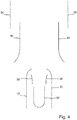
- a first exhaust gas ejection device is shown in cross section.
- the exhaust gas ejection device consists of a first pipe 10 into which hot exhaust gas is introduced from below and from which exhaust gas cooled above is ejected.
- a second tube 20 is arranged in the first tube 10. This is closed at the bottom and open at the top. Cold air is entrained from the second pipe 20 by the gas flow of the warm exhaust gas. Alternatively or additionally, cold air can also be actively conveyed from the second pipe 20.
- a first diffuser ring 30 is arranged above the second tube 20.
- Fig. 2 Fig. 10 shows a second exhaust gas ejector which is comparable to the first exhaust gas ejector. The only difference is that the first tube 10 has a constriction at the top in order to increase the flow velocity at the outlet.
- a third exhaust gas ejection device which has a third pipe 40 in addition to the second exhaust gas ejection device.
- the third tube 40 is advantageously widened somewhat on its underside, as shown, in order to additionally suck in more cold ambient air.
- FIG. 4 A fourth exhaust gas ejection device is shown which, in addition to the third exhaust gas ejection device, has a fourth pipe 50, the third pipe 40 being partially arranged within the fourth pipe 50. As a result, cold ambient air is drawn in in a further stage.
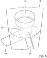
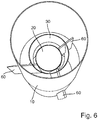
- Fig. 5 Fig. 3 shows a fifth exhaust gas ejector.
- the second pipe 20 is arranged inside the first pipe 10 and is supplied with cold air via three air inlets 60.
- the cold air can flow passively or actively through the air supply lines 60.
- the air inlets 60 carry the second pipe 20 within the first pipe 10.
- the first diffuser ring 30 is arranged above the second pipe 20.
Landscapes
- Engineering & Computer Science (AREA)
- Chemical & Material Sciences (AREA)
- Combustion & Propulsion (AREA)
- Mechanical Engineering (AREA)
- General Engineering & Computer Science (AREA)
- Health & Medical Sciences (AREA)
- Ocean & Marine Engineering (AREA)
- Chemical Kinetics & Catalysis (AREA)
- Toxicology (AREA)
- Exhaust Silencers (AREA)
- Crystals, And After-Treatments Of Crystals (AREA)
- Filling Or Discharging Of Gas Storage Vessels (AREA)
- Sampling And Sample Adjustment (AREA)
Description
Die Erfindung betrifft eine Vorrichtung zur Verringerung der Wärmesignatur eines Fahrzeugs, insbesondere eines Wasserfahrzeugs.The invention relates to a device for reducing the heat signature of a vehicle, in particular a watercraft.
Energie wird in Fahrzeugen, beispielsweise Wasserfahrzeugen, zum Beispiel Korvetten oder Fregatten, üblicherweise mittels Verbrennungsmotoren, beispielsweise aus Diesel oder Gas, gewonnen. Bei der Verbrennung entstehen bekannter Maßen heiße Abgase. Diese Abgase werden in die Umluft abgegeben. Hierdurch entstehen warme Bereiche in der Luft und auch die Umgebung, in welcher die Luft austritt, erwärmt sich regelmäßig. Hierdurch ist eine Ortung des Fahrzeuges im Infrarotbereich sehr leicht möglich.Energy is generated in vehicles, for example watercraft, for example corvettes or frigates, usually by means of internal combustion engines, for example from diesel or gas. It is known that hot exhaust gases are produced during combustion. These exhaust gases are released into the circulating air. This creates warm areas in the air and the environment in which the air escapes also warms up regularly. This makes it very easy to locate the vehicle in the infrared range.
Daher wird regelmäßig versucht, den Abgasstrom abzukühlen, bevor dieser an die Umgebung abgegeben wird und so die Signatur des Fahrzeuges zu verringern. Insbesondre in einer Gefechtssituation kann dieses von besonderer Bedeutung sein.Therefore, attempts are regularly made to cool the exhaust gas flow before it is released into the environment, thus reducing the vehicle's signature. This can be of particular importance in a combat situation in particular.
Aus der
Aus der
Aus der
Aus der
Aus der
Aus der
Aus der
Aus der
Nachteil dieser Formen ist, dass diese regelmäßig einen vergleichsweise großen Strömungswiderstand aufweisen, welcher den Abgasstrom bremst und eine Gegenkraft auf den Motor erzeugt bzw. eine aktive Förderung im Gasstrom erfordert.The disadvantage of these shapes is that they regularly have a comparatively high flow resistance, which brakes the exhaust gas flow and generates a counterforce on the engine or requires active delivery in the gas flow.
Aufgabe der Erfindung ist es, eine Vorrichtung für ein Wasserfahrzeug bereitzustellen, bei welcher ein Optimum aus Strömungswiderstand, Kühlung des Abgasstromes, Wirtschaftlichkeit und Robustheit der Vorrichtung und somit eine effiziente Reduzierung der Wärmesignatur ermöglicht.The object of the invention is to provide a device for a watercraft in which an optimum of flow resistance, cooling of the exhaust gas flow, economy and robustness of the device and thus an efficient reduction of the heat signature is possible.
Gelöst wird diese Aufgabe durch eine Abgasausstoßvorrichtung für ein Wasserfahrzeug mit den in Anspruch 1 angegebenen Merkmalen. Vorteilhafte Weiterbildungen ergeben sich aus den Unteransprüchen, der nachfolgenden Beschreibung sowie den Zeichnungen.This object is achieved by an exhaust gas ejection device for a watercraft with the features specified in claim 1. Advantageous developments result from the subclaims, the following description and the drawings.
Die erfindungsgemäße Abgasausstoßvorrichtung für ein Wasserfahrzeug weist ein erstes Rohr auf, wobei heißes Abgas durch das erste Rohr leitbar ist. Das erste Rohr weist einen kreisförmigen oder elliptischen Querschnitt auf, wobei der Radius des ersten Rohres in Abhängigkeit von der Höhe variieren kann. Im Inneren des ersten Rohres ist ein zweites Rohr angeordnet. Das zweite Rohr ist nach unten geschlossen. Das zweite Rohr weist einen kreisförmigen oder elliptischen Querschnitt auf, wobei der Radius des zweiten Rohres in Abhängigkeit von der Höhe variieren kann. Der Radius des ersten Rohres ist größer als der Radius des zweiten Rohres. Umgebungsluft ist durch das zweite Rohr leitbar. Oberhalb des zweiten Rohres und innerhalb des ersten Rohres ist ein erster Diffusorring angeordnet. Damit Abgas aus dem ersten Rohr austreten kann ergibt sich somit, dass der Radius des ersten Rohres bei einer gegebenen Höhe größer ist als der Radius des zweiten Rohres. Es ergibt sich somit ein erster Luftspalt, durch den das Abgas strömen kann, wobei der erste Luftspalt die Dicke der Differenz zwischen dem Radius des ersten Rohres und dem Radius des zweiten Rohres aufweist. Da die Radien abhängig von der Höhe sein können, kann auch die Dicke des ersten Luftspalts höhenabhängig sein. Vorzugsweise beträgt die Dicke des ersten Luftspalts wenigstes 3 %, weiter bevorzugt wenigstes 8 %, besonders bevorzugt wenigstens 15 % des Radius des ersten Rohres. Vorzugsweise beträgt die Dicke des ersten Luftspalts höchstens 80 %, weiter bevorzugt wenigstens 60 %, besonders bevorzugt wenigstens 35 % des Radius des ersten Rohres. Der erste Diffusorring weist einen kreisförmigen oder elliptischen Querschnitt auf. Der der Radius des ersten Diffusorrings ist an der dem zweiten Rohr benachbarten Seite größer als der Radius des zweiten Rohres (20) an der dem ersten Diffusorring (30) benachbarten Seite. Hierdurch entsteht ein Spalt, sodass das heiße Abgass nicht nur außen um den ersten Diffusorring strömt, sondern auch auf die Innenseite des Diffusorringes gelangt. Der Diffusorring wird somit beidseitig von heißem Abgas angeströmt, wobei das Abgas auf der Innenseite sich bereits mit der kalten Umgebungsluft vermischt, welche über das zweite Rohr zugeführt wird.The exhaust gas ejection device according to the invention for a watercraft has a first pipe, with hot exhaust gas being able to be conducted through the first pipe. The first tube has a circular or elliptical cross section, wherein the radius of the first tube can vary depending on the height. A second tube is arranged inside the first tube. The second tube is closed at the bottom. The second tube has a circular or elliptical cross section, wherein the radius of the second tube can vary depending on the height. The radius of the first tube is larger than the radius of the second tube. Ambient air can be conducted through the second pipe. A first diffuser ring is arranged above the second tube and inside the first tube. So that exhaust gas can exit from the first pipe, the result is that the radius of the first pipe is greater than the radius of the second pipe at a given height. This results in a first air gap through which the exhaust gas can flow, the first air gap having the thickness of the difference between the radius of the first pipe and the radius of the second pipe. Since the radii can be dependent on the height, the thickness of the first air gap can also be dependent on the height. The thickness of the first air gap is preferably at least 3%, more preferably at least 8%, particularly preferably at least 15% of the radius of the first tube. The thickness of the first air gap is preferably at most 80%, more preferably at least 60%, particularly preferably at least 35% of the radius of the first tube. The first diffuser ring has a circular or elliptical cross section. The radius of the first diffuser ring is larger on the side adjacent to the second tube than the radius of the second tube (20) on the side adjacent to the first diffuser ring (30). This creates a gap so that the hot exhaust gas not only flows around the outside of the first diffuser ring, but also also reaches the inside of the diffuser ring. The diffuser ring is thus exposed to hot exhaust gas on both sides, with the exhaust gas already mixing on the inside with the cold ambient air which is supplied via the second pipe.
Die durch das zweite Rohr leitbare Umgebungsluft dient der Abkühlung des Abgasstromes im ersten Rohr. Um eine Vermischung der beiden Luftströme zu erreichen ohne einen großen Strömungswiderstand zu erreichen ist ein Diffusorring oberhalb des zweiten Rohres angeordnet.The ambient air that can be conducted through the second pipe is used to cool the exhaust gas flow in the first pipe. A diffuser ring is arranged above the second pipe in order to achieve a mixing of the two air streams without achieving great flow resistance.
In einer weiteren Ausführungsform der Erfindung fallen die Symmetrieachse des ersten Rohres und die Symmetrieachse des zweiten Rohres zusammen.In a further embodiment of the invention, the axis of symmetry of the first tube and the axis of symmetry of the second tube coincide.
In einer weiteren Ausführungsform der Erfindung ist das zweite Rohr am unteren Ende spitz zulaufend. Beispielsweise ist das untere Ende des zweiten Rohres kegelförmig ausgebildet.In a further embodiment of the invention, the second tube tapers to a point at the lower end. For example, the lower end of the second tube is conical.
In einer weiteren Ausführungsform der Erfindung ist das zweite Rohr am unteren Ende abgerundet. Beispielsweise ist das untere Ende des zweiten Rohres halbkugelförmig. Diese Form bildet sich zum Beispiel auch bei Tropfen aus und ist besonders strömungsgünstig.In a further embodiment of the invention, the second tube is rounded at the lower end. For example, the lower end of the second tube is hemispherical. This shape is also formed in the case of drops, for example, and is particularly streamlined.
In einer weiteren Ausführungsform der Erfindung weist der Radius des ersten Diffusorrings in Abhängigkeit von der Höhe variieren kann. Die Symmetrieachse des ersten Diffusorrings und die Symmetrieachse des zweiten Rohres fallen zusammen.In a further embodiment of the invention, the radius of the first diffuser ring can vary as a function of the height. The axis of symmetry of the first diffuser ring and the axis of symmetry of the second tube coincide.
In einer weiteren Ausführungsform der Erfindung ist die Form des Diffusorrings derart gewählt, dass seine innere Fläche wenigstens stellenweise parallel zur oberen Umfangsfläche des zweiten Rohrs verläuft. Besonders bevorzugt ist nur die untere Umfangsfläche des Diffusorrings parallel zur oberen Umfangsfläche des zweiten Rohres.In a further embodiment of the invention, the shape of the diffuser ring is chosen such that its inner surface runs at least in places parallel to the upper peripheral surface of the second tube. It is particularly preferred that only the lower circumferential surface of the diffuser ring is parallel to the upper circumferential surface of the second tube.
In einer weiteren Ausführungsform der Erfindung nimmt der Radius des ersten Diffusorrings von unten nach oben zu. Durch die Zunahme des Radius entsteht eine nach Außen gewölbte Form des Diffusorrings, im Querschnitt analog einer Tragflächenoberfläche. Hierdurch kommt es zu einer Verstärkung des Vermischungseffekts durch den Diffusorring. Es ergibt sich ein Druckunterschied zwischen dem inneren und dem äußeren Bereich des Diffusorrings. Durch die gewölbte Form strömt die Luft auf der Innenseite schneller, sodass analog zum Flugzeugflügel ein geringerer Druck entsteht. Durch diesen Druckunterschied kommt es zu einer effizienten Ansaugung der Umgebungsluft aus dem zweiten Rohr in das Innere des Diffusorrings, ohne dass eine aktive Luftzuführung in das zweite Rohr notwendig ist. Bevorzugt ist die Fläche des Diffusorrings nach außen gewölbt. Besonders bevorzugt lassen sich die Wölbung der inneren Fläche und der äußeren Fläche durch quadratische Funktionen annähern, wobei die Funktionen unterschiedlich zueinander sind. Zusätzlich kann zur Verstärkung das erste Rohr nach Innen gewölbt sein, wodurch es zu einer weiteren Drucksteigerung im äußeren Bereich zwischen dem ersten Rohr und dem Diffusorring kommt. Zusätzlich führt dieses dazu, dass das heiße Abgas zwischen dem ersten Rohr und dem Diffusorring beschleunigt wird. Hierdurch bildet sich hinter dem Diffusorring ein äußerer ringförmiger Gasstrom an der Wandseite, welche besonders beschleunigt ist. Hierdurch ergibt sich beim Austritt des Gasstroms aus dem ersten Rohr ein Effekt, welcher dem einer Wasserstrahlpumpe gleicht und zu einer effizienten Vermischung durch Mitnahme von das erste Rohr umgebender Umgebungsluft führt.In a further embodiment of the invention, the radius of the first diffuser ring increases from bottom to top. The increase in the radius creates an outwardly curved shape of the diffuser ring, similar in cross-section to a wing surface. This increases the mixing effect through the diffuser ring. There is a pressure difference between the inner and the outer area of the diffuser ring. Due to the arched shape, the air flows faster on the inside, so that, analogous to the aircraft wing, there is less pressure. This pressure difference results in an efficient suction of the ambient air from the second tube into the interior of the diffuser ring without an active air supply into the second pipe is necessary. The surface of the diffuser ring is preferably curved outwards. The curvature of the inner surface and the outer surface can particularly preferably be approximated by quadratic functions, the functions being different from one another. In addition, the first tube can be curved inward for reinforcement, which leads to a further increase in pressure in the outer area between the first tube and the diffuser ring. In addition, this leads to the fact that the hot exhaust gas is accelerated between the first pipe and the diffuser ring. As a result, behind the diffuser ring, an outer ring-shaped gas flow forms on the wall side, which is particularly accelerated. As a result, when the gas flow emerges from the first pipe, an effect is produced which is similar to that of a water jet pump and leads to efficient mixing by entrainment of the ambient air surrounding the first pipe.
In einer weiteren Ausführungsform der Erfindung ist der Diffusorring am unteren Ende abgerundet und am oberen Ende spitz ausgeformt.In a further embodiment of the invention, the diffuser ring is rounded at the lower end and has a pointed shape at the upper end.
In einer weiteren Ausführungsform der Erfindung ist der Radius des ersten Rohres bei einer gegebenen Höhe größer ist als der Radius des Diffusorrings. Es ergibt sich somit ein zweiter Luftspalt, durch den das Abgas strömen kann, wobei der zweite Luftspalt die Dicke der Differenz zwischen dem Radius des ersten Rohres und dem Radius des Diffusorrings aufweist. Da die Radien abhängig von der Höhe sein können, kann auch die Dicke des zweiten Luftspalts höhenabhängig sein. Vorzugsweise beträgt die Dicke des zweiten Luftspalts wenigstes 2 %, weiter bevorzugt wenigstes 5 %, besonders bevorzugt wenigstens 10 % des Radius des ersten Rohres. Vorzugsweise beträgt die Dicke des zweiten Luftspalts höchstens 80 %, weiter bevorzugt wenigstens 60 %, besonders bevorzugt wenigstens 35 % des Radius des ersten Rohres.In a further embodiment of the invention, the radius of the first tube at a given height is greater than the radius of the diffuser ring. This results in a second air gap through which the exhaust gas can flow, the second air gap having the thickness of the difference between the radius of the first tube and the radius of the diffuser ring. Since the radii can be dependent on the height, the thickness of the second air gap can also be dependent on the height. The thickness of the second air gap is preferably at least 2%, more preferably at least 5%, particularly preferably at least 10% of the radius of the first tube. The thickness of the second air gap is preferably at most 80%, more preferably at least 60%, particularly preferably at least 35% of the radius of the first tube.
In einer weiteren Ausführungsform der Erfindung oberhalb des ersten Rohres ist ein drittes Rohr angeordnet. Das dritte Rohr weist einen kreisförmigen oder elliptischen Querschnitt auf, wobei der Radius des dritten Rohres in Abhängigkeit von der Höhe variieren kann. Der Radius des dritten Rohres ist größer als der Radius des ersten Rohres. Die Symmetrieachse des ersten Rohres und die Symmetrieachse des dritten Rohres fallen zusammen. Durch die Verwendung eines dritten Rohres kommt es zu einer weiteren Durchmischung zwischen dem heißen Abgas, welches mit dem aus der äußeren Umgebung kommenden kalten Luft hierdurch weiter durchmischt und abgekühlt wird. Es kommt somit zu einer ersten Abkühlung im Kern durch die durch das zweite Rohr geleitete Kaltluft sowie durch die von der Außenseite zugeführte Kaltluft im dritten Rohr.In a further embodiment of the invention, a third tube is arranged above the first tube. The third tube has a circular or elliptical cross section, wherein the radius of the third tube can vary depending on the height. The radius of the third pipe is larger than the radius of the first pipe. The axis of symmetry of the first tube and the axis of symmetry of the third tube coincide. The use of a third pipe results in further intermixing between the hot exhaust gas, which is further intermixed and cooled with the cold air coming from the external environment. There is thus a first cooling in the core through the cold air conducted through the second tube and through the cold air supplied from the outside in the third tube.
In einer weiteren Ausführungsform der Erfindung ist oberhalb des dritten Rohres ein viertes Rohr angeordnet. Das vierte Rohr weist einen kreisförmigen oder elliptischen Querschnitt auf, wobei der Radius des vierten Rohres in Abhängigkeit von der Höhe variieren kann. Der kleinste Radius des vierten Rohres ist größer als der größte Radius des dritten Rohres, wobei die Symmetrieachse des dritten Rohres und die Symmetrieachse des vierten Rohres zusammenfallen. Das dritte Rohr kann teilweise innerhalb des vierten Rohres angeordnet sein. Das dritte Rohr kann alternativ oder zusätzlich auch am oberen Ende verjüngt ausgeführt sein. Durch die zusätzliche Verwendung eines vierten Rohres mit größerem Durchmesser, bildet sich ein Luftspalt zwischen dem dritten und vierten Rohr über den Umgebungsluft in den Abgasstrom zugeführt wird. Es kommt zu einer zweiten Vermischungsstufe mit kalter Umgebungsluft zu einer weiteren Abkühlung des Abgases. In einer Weiterbildung der Erfindung ist noch ein fünftes Rohr oberhalb des vierten Rohr angeordnet und weist in analoger Weise einen größeren Radius als das vierte Rohr auf. Es bildet sich ein weiterer Luftspalt, durch den eine weitere Durchmischung erreicht werden kann.In a further embodiment of the invention, a fourth pipe is arranged above the third pipe. The fourth tube has a circular or elliptical cross section, wherein the radius of the fourth tube can vary depending on the height. The smallest radius of the fourth tube is larger than the largest radius of the third tube, the axis of symmetry of the third tube and the axis of symmetry of the fourth tube coinciding. The third tube can be arranged partially within the fourth tube. As an alternative or in addition, the third tube can also be tapered at the upper end. The additional use of a fourth pipe with a larger diameter creates an air gap between the third and fourth pipe through which ambient air is fed into the exhaust gas flow. In a second stage of mixing with cold ambient air, the exhaust gas is cooled further. In a further development of the invention, a fifth pipe is also arranged above the fourth pipe and, in an analogous manner, has a larger radius than the fourth pipe. Another air gap is formed through which further mixing can be achieved.
In einer weiteren Ausführungsform der Erfindung sind wenigstens drei Luftzuführungen so angeordnet, dass diese Luft von außerhalb des ersten Rohres in des Innere des zweiten Rohres leiten. Die Luftzuführung kann beispielsweise in der Form eines Rohres ausgeführt sein. Durch die Luftzuführung kann kalte Umgebungsluft in das zweite Rohr gelangen, um den Kern das Abgasstromes abzukühlen, ohne vorher mit Abgas vermischt worden zu sein. Gleichzeitig stellen wenige, beispielsweise drei Luftzuführungen, nur einen geringen Strömungswiderstand dar.In a further embodiment of the invention, at least three air inlets are arranged in such a way that they direct air from outside the first tube into the interior of the second tube. The air supply can for example be designed in the form of a tube. Through the air supply, cold ambient air can get into the second pipe in order to cool the core of the exhaust gas flow without having been mixed with exhaust gas beforehand. At the same time, a few, for example three air inlets, only represent a low flow resistance.
In einer weiteren Ausführungsform der Erfindung dienen die wenigstens drei Luftzuführungen zur Stütze des zweiten Rohres. Um das zweite Rohr im Inneren des ersten Rohres zu halten, ist eine Stützung notwendig. Wird die Stützung durch die Luftzuführung übernommen, entfallen weitere Bauteile, sodass weniger Strömungswiderstand entsteht.In a further embodiment of the invention, the at least three air inlets serve to support the second tube. In order to hold the second pipe inside the first pipe, a support is necessary. If the support is taken over by the air supply, further components are omitted, so that there is less flow resistance.
In einer weiteren Ausführungsform der Erfindung weisen die Luftzuführungen einen tropfenförmigen Querschnitt auf. Der tropfenförmige Querschnitt (unten rund und breit, oben spitz zulaufend) ist strömungsoptimiert und führt weiter dazu, dass dem Abgasstrom ein möglichst geringer Strömungswiderstand entgegensteht.In a further embodiment of the invention, the air inlets have a teardrop-shaped cross section. The drop-shaped cross-section (round and wide at the bottom, tapering to a point at the top) is flow-optimized and also means that the flow of exhaust gas is opposed to the lowest possible flow resistance.
In einer weiteren Ausführungsform der Erfindung sind die wenigstens drei Luftzuführungen derart ausgebildet, dass der durch das erste Rohr strömende Abgasstrom durch die wenigstens drei Luftzuführungen in Rotation versetzt wird. Hierzu weisen die Luftzuführungen einen von der Rotationssymmetrie abweichenden Querschnitt auf. Insbesondere kann der Querschnitt analog einer Tragfläche geformt werden und somit eine Saug- und eine Druckseite aufweisen. Die Luftzuführungen sind dabei vorteilhafter Weise derart angeordnet, dass die Saugseite einer Luftzuführung zur Druckseite einer anderen Luftzuführung benachbart ist, wodurch sich eine Kreisbewegung im Abgasstrom ergibt.In a further embodiment of the invention, the at least three air inlets are designed in such a way that the exhaust gas flow flowing through the first pipe passes through the at least three Air inlets is set in rotation. For this purpose, the air supply lines have a cross-section deviating from the rotational symmetry. In particular, the cross section can be shaped like a wing and thus have a suction side and a pressure side. The air supplies are advantageously arranged in such a way that the suction side of one air supply is adjacent to the pressure side of another air supply, which results in a circular movement in the exhaust gas flow.
In einer weiteren Ausführungsform der Erfindung weist die Abgasausstoßvorrichtung eine Fördervorrichtung auf, wobei die Fördervorrichtung zum Fördern von Luft durch die Luftzuführungen ausgebildet ist. Neben dem rein passiven Betrieb, in dem durch die Strömung des Abgases die kalte Umgebungsluft angesaugt wird, kann die kalte Umgebungsluft auch aktiv gefördert werden. Hierdurch erfolgt eine deutlich stärkere Abkühlung des Abgasstromes. Dieses hat jedoch auch einige Nachteile. Zum einen kommt es durch die zusätzliche aktive geförderte Gasmenge zu einem erhöhten Gegendruck gegen das Abgas. Zum anderen steigen Kosten und Verschleiß. Daher kann beispielsweise eine Fördervorrichtung vorgesehen sein, welche jedoch im Regelbetrieb nicht aktiv fördert und erst in einer Gefechtssituation aktiv hinzugeschaltet wird, um kurzfristig einen maximalen Kühlungseffekt zu erzielen.In a further embodiment of the invention, the exhaust gas ejection device has a delivery device, the delivery device being designed to deliver air through the air supply lines. In addition to the purely passive operation, in which the cold ambient air is sucked in by the flow of the exhaust gas, the cold ambient air can also be actively conveyed. This results in a significantly stronger cooling of the exhaust gas flow. However, this also has some disadvantages. On the one hand, the additional active amount of gas delivered leads to an increased counter pressure against the exhaust gas. On the other hand, costs and wear increase. Therefore, for example, a conveying device can be provided which, however, does not actively convey in regular operation and is only actively switched on in a combat situation in order to achieve a maximum cooling effect in the short term.
In einer weiteren Ausführungsform der Erfindung ist oberhalb des ersten Diffusorring und innerhalb des ersten Rohres einen zweiter Diffusorring angeordnet. Weist die Abgasausstoßvorrichtung ein drittes Rohr auf, so ist der zweite Diffusorring vorzugsweise zwischen dem ersten Diffusorring und dem dritten Rohr angeordnet.In a further embodiment of the invention, a second diffuser ring is arranged above the first diffuser ring and inside the first tube. If the exhaust gas ejection device has a third pipe, the second diffuser ring is preferably arranged between the first diffuser ring and the third pipe.
In einer weiteren Ausführungsform der Erfindung eine Abgasausstoßvorrichtung mit einer Wassereinspritzvorrichtung. Die Wassereinspritzung kann an einer oder an mehreren Stellen erfolgen. Vorteil der Wassereinspritzung ist die extrem effiziente Kühlung, zum einen durch die sehr hohe Wärmekapazität von Wasser zum anderen durch die Ausnutzung der ebenfalls vergleichsweise hohen Verdampfungsenthalphie. Nachteilig sind jedoch die Kosten, sowie die ständige Anwesenheit von Wasser im Bereich. Daher wird eine Wassereinspritzung vorzugsweise nur optional hinzugeschaltet, wenn eine intensive Kühlung, beispielsweise im Gefechtsfall, unerlässlich ist.In a further embodiment of the invention, an exhaust gas ejection device with a water injection device. The water injection can take place in one or more places. The advantage of water injection is the extremely efficient cooling, on the one hand through the very high heat capacity of water and on the other hand through the utilization of the likewise comparatively high enthalpy of evaporation. However, the disadvantage is the cost and the constant presence of water in the area. Therefore, water injection is preferably only switched on optionally if intensive cooling, for example in the event of a battle, is essential.
In einem weiteren Aspekt betrifft die Erfindung ein Wasserfahrzeug mit einer erfindungsgemäßen Abgasausstoßvorrichtung, bevorzugt handelt es sich um ein militärisches Wasserfahrzeug.In a further aspect, the invention relates to a watercraft with an exhaust gas ejection device according to the invention, preferably a military watercraft.
In einem weiteren Aspekt betrifft die Erfindung ein Verfahren zum Betreiben einer Abgasausstoßvorrichtung, wobei die Abgasausstoßvorrichtung über eine Fördervorrichtung zum Fördern von Luft und eine Wassereinspritzvorrichtung aufweist. Die Vorrichtung kann in vier prinzipiellen Betriebszuständen gefahren werden. Im rein passiven Betrieb erfolgt weder aktive Förderung von Luft noch eine Wassereinspritzung. Im aktiven Betrieb erfolgt eine aktive Förderung von Luft, jedoch keine Wassereinspritzung. Im Intensivbetrieb erfolgt eine aktive Förderung von Luft und eine Wassereinspritzung. Im Feuchtbetrieb erfolgt nur eine Wassereinspritzung aber keine aktive Förderung von Luft. Das Verfahren umfasst in einem ersten Verfahrensschritt die Vorgabe der Einsatzparameter. In einem zweiten Schritt wird der zu den Einsatzparametern passende Betriebszustand ausgewählt.In a further aspect, the invention relates to a method for operating an exhaust gas ejection device, the exhaust gas ejection device having a conveying device for conveying air and a water injection device. The device can be operated in four basic operating states. In purely passive mode, there is neither active delivery of air nor water injection. In active operation, air is actively conveyed, but no water injection. In intensive operation, air is actively conveyed and water is injected. In humid operation, only water is injected, but no active air delivery. In a first process step, the method includes the specification of the operational parameters. In a second step, the operating status that matches the application parameters is selected.
Beispielsweise wird als Einsatzparameter die einfache Überführungsfahrt vorgegeben. In diesem Fall sind ökonomische Gesichtspunkte überwiegend, so dass der passive Betrieb ausgewählt wird. Wird als Einsatzparameter eine Überwachungsfahrt ausgewählt, so ist für einen langen Zeitraum die Signatur so gering wie möglich zu halten, der Betrieb jedoch für eine möglichst lange Standzeit auf See auszulegen. Daher wird für diesen Fall der aktive Betrieb ausgewählt. In einer Gefechts- oder Beschusssituation ist die Minimierung der Signatur absolut vorranging, sodass in diesem Fall der Intensivbetrieb ausgewählt wird.For example, the simple transfer trip is specified as the application parameter. In this case, economic considerations are predominant, so passive operation is selected. If a surveillance voyage is selected as the operational parameter, the signature must be kept as small as possible for a long period of time, but the operation must be designed for the longest possible downtime at sea. Active operation is therefore selected for this case. In a combat or fire situation, the minimization of the signature is absolutely paramount, so that in this case intensive operation is selected.
Nachfolgend ist die erfindungsgemäße Abgasausstoßvorrichtung anhand eines in den Zeichnungen dargestellten Ausführungsbeispiels näher erläutert.
- Fig. 1
- Querschnitt durch eine erste Abgasausstoßvorrichtung
- Fig. 2
- Querschnitt durch eine zweite Abgasausstoßvorrichtung
- Fig. 3
- Querschnitt durch eine dritte Abgasausstoßvorrichtung
- Fig. 4
- Querschnitt durch eine vierte Abgasausstoßvorrichtung
- Fig. 5
- Schematische Ansicht einer fünften Abgasausstoßvorrichtung
- Fig. 1
- Cross section through a first exhaust gas ejection device
- Fig. 2
- Cross section through a second exhaust gas ejection device
- Fig. 3
- Cross section through a third exhaust gas ejection device
- Fig. 4
- Cross section through a fourth exhaust gas ejection device
- Fig. 5
- Schematic view of a fifth exhaust gas ejection device
In
In
Als weitere Ausgestaltung ist in
Bezugszeichen
- 10
- erstes Rohr
- 20
- zweites Rohr
- 30
- erster Diffusorring
- 40
- drittes Rohr
- 50
- viertes Rohr
- 60
- Luftzuführung
- 10
- first pipe
- 20th
- second tube
- 30th
- first diffuser ring
- 40
- third pipe
- 50
- fourth pipe
- 60
- Air supply
Claims (11)
- Exhaust gas output device for a watercraft, wherein the exhaust gas output device has a first pipe (10), wherein hot exhaust gas can be directed through the first pipe (10), wherein the first pipe (10) has a circular or elliptical cross section, wherein the radius of the first pipe (10) can vary according to the height, wherein a second pipe (20) is arranged inside the first pipe (10), wherein the second pipe (20) is closed at the bottom, wherein the second pipe (20) has a circular or elliptical cross section, wherein the radius of the second pipe (20) can vary according to the height, wherein the radius of the first pipe (10) is larger than the radius of the second pipe (20), wherein ambient air can be directed through the second pipe (20), characterized in that a first diffuser ring (30) is arranged above the second pipe (20) and within the first pipe, wherein the first diffuser ring (30) has a circular or elliptical cross section, wherein the radius of the first diffuser ring (30) is larger on the side adjacent to the second pipe (20) than the radius of the second pipe (20) on the side adjacent to the first diffuser ring (30).
- Exhaust gas output device according to Claim 1, characterized in that the radius of the first diffuser ring (30) can vary according to the height and wherein the axis of symmetry of the first diffuser ring (30) and the axis of symmetry of the second pipe (20) coincide.
- Exhaust gas output device according to Claim 3, characterized in that the radius of the first diffuser ring (30) increases from the bottom up.
- Exhaust gas output device according to one of the preceding claims, characterized in that a third pipe (40) is arranged above the first pipe (10), wherein the third pipe (40) has a circular or elliptical cross section, wherein the radius of the third pipe (40) can vary according to the height, wherein the radius of the third pipe (40) is larger than the radius of the first pipe (10), wherein the axis of symmetry of the first pipe (10) and the axis of symmetry of the third pipe (40) coincide.
- Exhaust gas output device according to Claim 4, characterized in that a fourth pipe (50) is arranged above the third pipe (40), wherein the fourth pipe (50) has a circular or elliptical cross section, wherein the radius of the fourth pipe (50) can vary according to the height, wherein the radius of the fourth pipe (50) is larger than the radius of the third pipe (40), wherein the axis of symmetry of the third pipe (40) and the axis of symmetry of the fourth pipe (50) coincide, wherein the third pipe (40) is arranged partially within the fourth pipe (50) .
- Exhaust gas output device according to one of the preceding claims, characterized in that at least three air feed ducts (60) are arranged in such a way that they direct air from outside the first pipe (10) into the interior of the second pipe (20).
- Exhaust gas output device according to Claim 6, characterized in that the at least three air feed ducts (60) serve to support the second pipe (20).
- Exhaust gas output device according to Claim 6 or 7, characterized in that the air feed ducts (60) have a drop-shaped cross section.
- Exhaust gas output device according to one of Claims 6 to 8, characterized in that the at least three air feed ducts (60) are designed in such a way that the exhaust gas flow flowing through the first pipe (10) is set in rotation by the at least three air feed ducts (60).
- Exhaust gas output device according to one of Claims 6 to 9, characterized in that the exhaust gas output device has a delivery device, wherein the delivery device is designed to deliver air through the air feed ducts (60).
- Exhaust gas output device according to one of the preceding claims, characterized in that a second diffuser ring is arranged above the first diffuser ring (30) and within the first pipe (10).
Priority Applications (1)
| Application Number | Priority Date | Filing Date | Title |
|---|---|---|---|
| PL17740740T PL3488089T3 (en) | 2016-07-21 | 2017-07-18 | Exhaust emission device for a marine vessel |
Applications Claiming Priority (2)
| Application Number | Priority Date | Filing Date | Title |
|---|---|---|---|
| DE102016213381.0A DE102016213381A1 (en) | 2016-07-21 | 2016-07-21 | Exhaust emission device for a watercraft |
| PCT/EP2017/068076 WO2018015358A1 (en) | 2016-07-21 | 2017-07-18 | Exhaust gas output device for a watercraft |
Publications (2)
| Publication Number | Publication Date |
|---|---|
| EP3488089A1 EP3488089A1 (en) | 2019-05-29 |
| EP3488089B1 true EP3488089B1 (en) | 2020-09-02 |
Family
ID=59366430
Family Applications (1)
| Application Number | Title | Priority Date | Filing Date |
|---|---|---|---|
| EP17740740.0A Active EP3488089B1 (en) | 2016-07-21 | 2017-07-18 | Exhaust emission device for a marine vessel |
Country Status (12)
| Country | Link |
|---|---|
| EP (1) | EP3488089B1 (en) |
| KR (1) | KR102181068B1 (en) |
| BR (1) | BR112019001063A2 (en) |
| CL (1) | CL2019000139A1 (en) |
| CO (1) | CO2019000502A2 (en) |
| DE (1) | DE102016213381A1 (en) |
| ES (1) | ES2824778T3 (en) |
| PE (1) | PE20190307A1 (en) |
| PL (1) | PL3488089T3 (en) |
| PT (1) | PT3488089T (en) |
| RU (1) | RU2704508C1 (en) |
| WO (1) | WO2018015358A1 (en) |
Families Citing this family (1)
| Publication number | Priority date | Publication date | Assignee | Title |
|---|---|---|---|---|
| KR102290919B1 (en) * | 2020-12-23 | 2021-08-19 | 주식회사 한국종합기계 | Seawater spray type infrared signature suppression system |
Family Cites Families (14)
| Publication number | Priority date | Publication date | Assignee | Title |
|---|---|---|---|---|
| US4214441A (en) | 1978-09-12 | 1980-07-29 | The United States Of America As Represented By The Secretary Of The Navy | Infrared suppressor device |
| DE3743798A1 (en) * | 1987-12-23 | 1989-07-13 | Marinetechnik Gmbh | Surface vessel, in particular for military purposes |
| JPH05171917A (en) * | 1991-12-19 | 1993-07-09 | Mitsubishi Heavy Ind Ltd | Infrared ray radiation reducing device |
| DE19504183A1 (en) * | 1995-02-09 | 1996-08-14 | Eberspaecher J | Diesel engine particle filter regenerating burner |
| DE19902310A1 (en) | 1999-01-21 | 2000-07-27 | Volkswagen Ag | Gas pipe system, in particular exhaust pipe system for a vehicle internal combustion engine |
| US7284364B2 (en) | 2003-09-08 | 2007-10-23 | Northrop Grumman Ship Systems, Inc. | Passive exhaust suppressor and method |
| US20080129053A1 (en) * | 2004-05-12 | 2008-06-05 | Piercey Gerald S | Engine-generator set |
| DE602005018060D1 (en) * | 2005-09-28 | 2010-01-14 | David Blennerhassett | exhaust diffuser |
| US8056327B2 (en) * | 2006-04-25 | 2011-11-15 | International Truck Intellectual Property Company, Llc | Micro-venturi exhaust cooling device |
| US20090139217A1 (en) * | 2007-12-03 | 2009-06-04 | International Truck Intellectual Property Company, Llc | Exhaust gas temperature reduction device for aftertreatment devices |
| CN101896693B (en) * | 2007-12-18 | 2013-11-13 | 马克卡车公司 | Exhaust diffuser for a truck |
| US7833301B2 (en) * | 2008-05-30 | 2010-11-16 | Deere & Company | Engine exhaust cooler and air pre-cleaner aspirator |
| US8468811B2 (en) * | 2009-06-22 | 2013-06-25 | Paccar Inc | Thermal diffuser |
| US8671671B1 (en) * | 2011-07-14 | 2014-03-18 | Northern California Diagnostic Laboratories | Exhaust system for an internal combustion engine |
-
2016
- 2016-07-21 DE DE102016213381.0A patent/DE102016213381A1/en not_active Withdrawn
-
2017
- 2017-07-18 PE PE2019000229A patent/PE20190307A1/en unknown
- 2017-07-18 BR BR112019001063-7A patent/BR112019001063A2/en active Search and Examination
- 2017-07-18 PL PL17740740T patent/PL3488089T3/en unknown
- 2017-07-18 EP EP17740740.0A patent/EP3488089B1/en active Active
- 2017-07-18 PT PT177407400T patent/PT3488089T/en unknown
- 2017-07-18 RU RU2019102232A patent/RU2704508C1/en active
- 2017-07-18 WO PCT/EP2017/068076 patent/WO2018015358A1/en unknown
- 2017-07-18 KR KR1020197004882A patent/KR102181068B1/en active IP Right Grant
- 2017-07-18 ES ES17740740T patent/ES2824778T3/en active Active
-
2019
- 2019-01-18 CO CONC2019/0000502A patent/CO2019000502A2/en unknown
- 2019-01-18 CL CL2019000139A patent/CL2019000139A1/en unknown
Non-Patent Citations (1)
| Title |
|---|
| None * |
Also Published As
| Publication number | Publication date |
|---|---|
| ES2824778T3 (en) | 2021-05-13 |
| CO2019000502A2 (en) | 2019-02-08 |
| PE20190307A1 (en) | 2019-03-01 |
| PT3488089T (en) | 2020-10-21 |
| WO2018015358A1 (en) | 2018-01-25 |
| EP3488089A1 (en) | 2019-05-29 |
| KR20190023109A (en) | 2019-03-07 |
| CL2019000139A1 (en) | 2019-05-03 |
| PL3488089T3 (en) | 2021-03-08 |
| RU2704508C1 (en) | 2019-10-29 |
| DE102016213381A1 (en) | 2018-01-25 |
| BR112019001063A2 (en) | 2019-05-07 |
| KR102181068B1 (en) | 2020-11-23 |
Similar Documents
| Publication | Publication Date | Title |
|---|---|---|
| DE60014553T2 (en) | Method and device for ice protection of an aircraft inlet | |
| EP2233836B1 (en) | Swirler, method for reducing flashback in a burner with at least one swirler and burner | |
| DE2656151C2 (en) | Device for separating solid impurities from a gas stream | |
| DE102014102780A1 (en) | System and method for air flow conditioning at a rape level | |
| EP0684428A2 (en) | Device for injecting air into the combustion space of a flare burner and flare burner | |
| DE1294394B (en) | Silencer for supersonic jet engines | |
| DE112012006100T5 (en) | Method for preventing deformation in a gas turbine housing, flushing device for carrying out this method and gas turbine provided with this device | |
| DE112014000848T5 (en) | Gas recirculation in turbodiesel engines | |
| EP3388649A1 (en) | Nacelle for a turbofan engine | |
| DE2159490A1 (en) | Exhaust system for an internal combustion engine and method for reducing the back pressure of the exhaust gases | |
| DE102018010103A1 (en) | Ringtank | |
| DE807450C (en) | Fuel evaporator for gas turbine combustion chambers | |
| DE1528909A1 (en) | Fluid propulsion system | |
| DE102014009015A1 (en) | Mixing device of an exhaust gas purification system of a motor vehicle internal combustion engine | |
| DE102012220358A1 (en) | Nozzle with guide devices | |
| DE102014113132A1 (en) | Aircraft with a storage chamber and a device for introducing oil | |
| EP3488089B1 (en) | Exhaust emission device for a marine vessel | |
| DE1808955A1 (en) | Muzzle for shotguns, especially shotguns | |
| EP3189934A1 (en) | Device for cleaning a jet engine | |
| WO2017025235A1 (en) | Compressor of a turbocharger having an air recirculation valve and turbocharger and motor vehicle having such a compressor | |
| DE102007036527B4 (en) | Nozzle arrangement for a gas turbine engine | |
| WO2016062610A1 (en) | Jet pump | |
| EP2012970B1 (en) | Device for producing a high-pressure jet | |
| EP3191692B1 (en) | Diffuser of a thermal energy machine and thermal energy machine | |
| DE102008062078B4 (en) | Entry level for a steam turbine |
Legal Events
| Date | Code | Title | Description |
|---|---|---|---|
| STAA | Information on the status of an ep patent application or granted ep patent |
Free format text: STATUS: UNKNOWN |
|
| STAA | Information on the status of an ep patent application or granted ep patent |
Free format text: STATUS: THE INTERNATIONAL PUBLICATION HAS BEEN MADE |
|
| PUAI | Public reference made under article 153(3) epc to a published international application that has entered the european phase |
Free format text: ORIGINAL CODE: 0009012 |
|
| STAA | Information on the status of an ep patent application or granted ep patent |
Free format text: STATUS: REQUEST FOR EXAMINATION WAS MADE |
|
| 17P | Request for examination filed |
Effective date: 20190221 |
|
| AK | Designated contracting states |
Kind code of ref document: A1 Designated state(s): AL AT BE BG CH CY CZ DE DK EE ES FI FR GB GR HR HU IE IS IT LI LT LU LV MC MK MT NL NO PL PT RO RS SE SI SK SM TR |
|
| AX | Request for extension of the european patent |
Extension state: BA ME |
|
| RAP1 | Party data changed (applicant data changed or rights of an application transferred) |
Owner name: THYSSENKRUPP AG Owner name: THYSSENKRUPP MARINE SYSTEMS GMBH |
|
| DAV | Request for validation of the european patent (deleted) | ||
| DAX | Request for extension of the european patent (deleted) | ||
| GRAP | Despatch of communication of intention to grant a patent |
Free format text: ORIGINAL CODE: EPIDOSNIGR1 |
|
| STAA | Information on the status of an ep patent application or granted ep patent |
Free format text: STATUS: GRANT OF PATENT IS INTENDED |
|
| INTG | Intention to grant announced |
Effective date: 20191210 |
|
| RAP1 | Party data changed (applicant data changed or rights of an application transferred) |
Owner name: THYSSENKRUPP AG Owner name: THYSSENKRUPP MARINE SYSTEMS GMBH |
|
| GRAS | Grant fee paid |
Free format text: ORIGINAL CODE: EPIDOSNIGR3 |
|
| GRAA | (expected) grant |
Free format text: ORIGINAL CODE: 0009210 |
|
| STAA | Information on the status of an ep patent application or granted ep patent |
Free format text: STATUS: THE PATENT HAS BEEN GRANTED |
|
| AK | Designated contracting states |
Kind code of ref document: B1 Designated state(s): AL AT BE BG CH CY CZ DE DK EE ES FI FR GB GR HR HU IE IS IT LI LT LU LV MC MK MT NL NO PL PT RO RS SE SI SK SM TR |
|
| REG | Reference to a national code |
Ref country code: GB Ref legal event code: FG4D Free format text: NOT ENGLISH |
|
| REG | Reference to a national code |
Ref country code: AT Ref legal event code: REF Ref document number: 1309047 Country of ref document: AT Kind code of ref document: T Effective date: 20200915 Ref country code: CH Ref legal event code: EP |
|
| REG | Reference to a national code |
Ref country code: DE Ref legal event code: R096 Ref document number: 502017007070 Country of ref document: DE |
|
| REG | Reference to a national code |
Ref country code: NL Ref legal event code: FP Ref country code: IE Ref legal event code: FG4D Free format text: LANGUAGE OF EP DOCUMENT: GERMAN |
|
| REG | Reference to a national code |
Ref country code: PT Ref legal event code: SC4A Ref document number: 3488089 Country of ref document: PT Date of ref document: 20201021 Kind code of ref document: T Free format text: AVAILABILITY OF NATIONAL TRANSLATION Effective date: 20201014 |
|
| REG | Reference to a national code |
Ref country code: SE Ref legal event code: TRGR |
|
| REG | Reference to a national code |
Ref country code: LT Ref legal event code: MG4D |
|
| PG25 | Lapsed in a contracting state [announced via postgrant information from national office to epo] |
Ref country code: NO Free format text: LAPSE BECAUSE OF FAILURE TO SUBMIT A TRANSLATION OF THE DESCRIPTION OR TO PAY THE FEE WITHIN THE PRESCRIBED TIME-LIMIT Effective date: 20201202 Ref country code: FI Free format text: LAPSE BECAUSE OF FAILURE TO SUBMIT A TRANSLATION OF THE DESCRIPTION OR TO PAY THE FEE WITHIN THE PRESCRIBED TIME-LIMIT Effective date: 20200902 Ref country code: BG Free format text: LAPSE BECAUSE OF FAILURE TO SUBMIT A TRANSLATION OF THE DESCRIPTION OR TO PAY THE FEE WITHIN THE PRESCRIBED TIME-LIMIT Effective date: 20201202 Ref country code: HR Free format text: LAPSE BECAUSE OF FAILURE TO SUBMIT A TRANSLATION OF THE DESCRIPTION OR TO PAY THE FEE WITHIN THE PRESCRIBED TIME-LIMIT Effective date: 20200902 Ref country code: LT Free format text: LAPSE BECAUSE OF FAILURE TO SUBMIT A TRANSLATION OF THE DESCRIPTION OR TO PAY THE FEE WITHIN THE PRESCRIBED TIME-LIMIT Effective date: 20200902 |
|
| PG25 | Lapsed in a contracting state [announced via postgrant information from national office to epo] |
Ref country code: RS Free format text: LAPSE BECAUSE OF FAILURE TO SUBMIT A TRANSLATION OF THE DESCRIPTION OR TO PAY THE FEE WITHIN THE PRESCRIBED TIME-LIMIT Effective date: 20200902 Ref country code: LV Free format text: LAPSE BECAUSE OF FAILURE TO SUBMIT A TRANSLATION OF THE DESCRIPTION OR TO PAY THE FEE WITHIN THE PRESCRIBED TIME-LIMIT Effective date: 20200902 |
|
| PG25 | Lapsed in a contracting state [announced via postgrant information from national office to epo] |
Ref country code: SM Free format text: LAPSE BECAUSE OF FAILURE TO SUBMIT A TRANSLATION OF THE DESCRIPTION OR TO PAY THE FEE WITHIN THE PRESCRIBED TIME-LIMIT Effective date: 20200902 Ref country code: EE Free format text: LAPSE BECAUSE OF FAILURE TO SUBMIT A TRANSLATION OF THE DESCRIPTION OR TO PAY THE FEE WITHIN THE PRESCRIBED TIME-LIMIT Effective date: 20200902 Ref country code: RO Free format text: LAPSE BECAUSE OF FAILURE TO SUBMIT A TRANSLATION OF THE DESCRIPTION OR TO PAY THE FEE WITHIN THE PRESCRIBED TIME-LIMIT Effective date: 20200902 Ref country code: CZ Free format text: LAPSE BECAUSE OF FAILURE TO SUBMIT A TRANSLATION OF THE DESCRIPTION OR TO PAY THE FEE WITHIN THE PRESCRIBED TIME-LIMIT Effective date: 20200902 |
|
| REG | Reference to a national code |
Ref country code: ES Ref legal event code: FG2A Ref document number: 2824778 Country of ref document: ES Kind code of ref document: T3 Effective date: 20210513 |
|
| PG25 | Lapsed in a contracting state [announced via postgrant information from national office to epo] |
Ref country code: IS Free format text: LAPSE BECAUSE OF FAILURE TO SUBMIT A TRANSLATION OF THE DESCRIPTION OR TO PAY THE FEE WITHIN THE PRESCRIBED TIME-LIMIT Effective date: 20210102 Ref country code: AL Free format text: LAPSE BECAUSE OF FAILURE TO SUBMIT A TRANSLATION OF THE DESCRIPTION OR TO PAY THE FEE WITHIN THE PRESCRIBED TIME-LIMIT Effective date: 20200902 |
|
| REG | Reference to a national code |
Ref country code: DE Ref legal event code: R097 Ref document number: 502017007070 Country of ref document: DE |
|
| PG25 | Lapsed in a contracting state [announced via postgrant information from national office to epo] |
Ref country code: SK Free format text: LAPSE BECAUSE OF FAILURE TO SUBMIT A TRANSLATION OF THE DESCRIPTION OR TO PAY THE FEE WITHIN THE PRESCRIBED TIME-LIMIT Effective date: 20200902 |
|
| PLBE | No opposition filed within time limit |
Free format text: ORIGINAL CODE: 0009261 |
|
| STAA | Information on the status of an ep patent application or granted ep patent |
Free format text: STATUS: NO OPPOSITION FILED WITHIN TIME LIMIT |
|
| 26N | No opposition filed |
Effective date: 20210603 |
|
| PG25 | Lapsed in a contracting state [announced via postgrant information from national office to epo] |
Ref country code: SI Free format text: LAPSE BECAUSE OF FAILURE TO SUBMIT A TRANSLATION OF THE DESCRIPTION OR TO PAY THE FEE WITHIN THE PRESCRIBED TIME-LIMIT Effective date: 20200902 Ref country code: DK Free format text: LAPSE BECAUSE OF FAILURE TO SUBMIT A TRANSLATION OF THE DESCRIPTION OR TO PAY THE FEE WITHIN THE PRESCRIBED TIME-LIMIT Effective date: 20200902 |
|
| REG | Reference to a national code |
Ref country code: CH Ref legal event code: PL |
|
| PG25 | Lapsed in a contracting state [announced via postgrant information from national office to epo] |
Ref country code: MC Free format text: LAPSE BECAUSE OF FAILURE TO SUBMIT A TRANSLATION OF THE DESCRIPTION OR TO PAY THE FEE WITHIN THE PRESCRIBED TIME-LIMIT Effective date: 20200902 |
|
| REG | Reference to a national code |
Ref country code: BE Ref legal event code: MM Effective date: 20210731 |
|
| PG25 | Lapsed in a contracting state [announced via postgrant information from national office to epo] |
Ref country code: LI Free format text: LAPSE BECAUSE OF NON-PAYMENT OF DUE FEES Effective date: 20210731 Ref country code: CH Free format text: LAPSE BECAUSE OF NON-PAYMENT OF DUE FEES Effective date: 20210731 |
|
| PG25 | Lapsed in a contracting state [announced via postgrant information from national office to epo] |
Ref country code: LU Free format text: LAPSE BECAUSE OF NON-PAYMENT OF DUE FEES Effective date: 20210718 |
|
| PG25 | Lapsed in a contracting state [announced via postgrant information from national office to epo] |
Ref country code: IE Free format text: LAPSE BECAUSE OF NON-PAYMENT OF DUE FEES Effective date: 20210718 Ref country code: BE Free format text: LAPSE BECAUSE OF NON-PAYMENT OF DUE FEES Effective date: 20210731 |
|
| PG25 | Lapsed in a contracting state [announced via postgrant information from national office to epo] |
Ref country code: CY Free format text: LAPSE BECAUSE OF FAILURE TO SUBMIT A TRANSLATION OF THE DESCRIPTION OR TO PAY THE FEE WITHIN THE PRESCRIBED TIME-LIMIT Effective date: 20200902 |
|
| PG25 | Lapsed in a contracting state [announced via postgrant information from national office to epo] |
Ref country code: HU Free format text: LAPSE BECAUSE OF FAILURE TO SUBMIT A TRANSLATION OF THE DESCRIPTION OR TO PAY THE FEE WITHIN THE PRESCRIBED TIME-LIMIT; INVALID AB INITIO Effective date: 20170718 |
|
| PGFP | Annual fee paid to national office [announced via postgrant information from national office to epo] |
Ref country code: NL Payment date: 20230719 Year of fee payment: 7 |
|
| REG | Reference to a national code |
Ref country code: AT Ref legal event code: MM01 Ref document number: 1309047 Country of ref document: AT Kind code of ref document: T Effective date: 20220718 |
|
| PG25 | Lapsed in a contracting state [announced via postgrant information from national office to epo] |
Ref country code: AT Free format text: LAPSE BECAUSE OF NON-PAYMENT OF DUE FEES Effective date: 20220718 |
|
| PGFP | Annual fee paid to national office [announced via postgrant information from national office to epo] |
Ref country code: TR Payment date: 20230717 Year of fee payment: 7 Ref country code: IT Payment date: 20230724 Year of fee payment: 7 Ref country code: GB Payment date: 20230721 Year of fee payment: 7 Ref country code: ES Payment date: 20230927 Year of fee payment: 7 |
|
| PGFP | Annual fee paid to national office [announced via postgrant information from national office to epo] |
Ref country code: SE Payment date: 20230719 Year of fee payment: 7 Ref country code: PT Payment date: 20230706 Year of fee payment: 7 Ref country code: PL Payment date: 20230707 Year of fee payment: 7 Ref country code: GR Payment date: 20230721 Year of fee payment: 7 Ref country code: FR Payment date: 20230726 Year of fee payment: 7 Ref country code: DE Payment date: 20230719 Year of fee payment: 7 |
|
| PG25 | Lapsed in a contracting state [announced via postgrant information from national office to epo] |
Ref country code: MK Free format text: LAPSE BECAUSE OF FAILURE TO SUBMIT A TRANSLATION OF THE DESCRIPTION OR TO PAY THE FEE WITHIN THE PRESCRIBED TIME-LIMIT Effective date: 20200902 |