EP3487324B1 - Fluid permeable heater assembly with cap - Google Patents
Fluid permeable heater assembly with cap Download PDFInfo
- Publication number
- EP3487324B1 EP3487324B1 EP17732387.0A EP17732387A EP3487324B1 EP 3487324 B1 EP3487324 B1 EP 3487324B1 EP 17732387 A EP17732387 A EP 17732387A EP 3487324 B1 EP3487324 B1 EP 3487324B1
- Authority
- EP
- European Patent Office
- Prior art keywords
- heater assembly
- heating element
- mesh
- cap
- aerosol
- Prior art date
- Legal status (The legal status is an assumption and is not a legal conclusion. Google has not performed a legal analysis and makes no representation as to the accuracy of the status listed.)
- Active
Links
- 239000012530 fluid Substances 0.000 title claims description 15
- 239000000463 material Substances 0.000 claims description 116
- 238000010438 heat treatment Methods 0.000 claims description 111
- 239000007788 liquid Substances 0.000 claims description 49
- 239000000758 substrate Substances 0.000 claims description 45
- 238000003860 storage Methods 0.000 claims description 20
- ATJFFYVFTNAWJD-UHFFFAOYSA-N Tin Chemical compound [Sn] ATJFFYVFTNAWJD-UHFFFAOYSA-N 0.000 description 25
- 238000004519 manufacturing process Methods 0.000 description 18
- 238000005520 cutting process Methods 0.000 description 16
- 239000004744 fabric Substances 0.000 description 11
- -1 polyethylene Polymers 0.000 description 11
- 229920000426 Microplastic Polymers 0.000 description 9
- 238000000465 moulding Methods 0.000 description 9
- 239000004696 Poly ether ether ketone Substances 0.000 description 7
- 229910052751 metal Inorganic materials 0.000 description 7
- 239000002184 metal Substances 0.000 description 7
- 229920002530 polyetherether ketone Polymers 0.000 description 7
- 238000004140 cleaning Methods 0.000 description 6
- 238000007689 inspection Methods 0.000 description 6
- 238000005979 thermal decomposition reaction Methods 0.000 description 6
- 241000208125 Nicotiana Species 0.000 description 5
- 235000002637 Nicotiana tabacum Nutrition 0.000 description 5
- 239000000443 aerosol Substances 0.000 description 5
- 239000000919 ceramic Substances 0.000 description 5
- 238000000034 method Methods 0.000 description 5
- 230000000391 smoking effect Effects 0.000 description 5
- 239000010935 stainless steel Substances 0.000 description 5
- 229910001220 stainless steel Inorganic materials 0.000 description 5
- OKTJSMMVPCPJKN-UHFFFAOYSA-N Carbon Chemical compound [C] OKTJSMMVPCPJKN-UHFFFAOYSA-N 0.000 description 4
- 239000004743 Polypropylene Substances 0.000 description 4
- 229910045601 alloy Inorganic materials 0.000 description 4
- 239000000956 alloy Substances 0.000 description 4
- 150000002739 metals Chemical class 0.000 description 4
- 229920001155 polypropylene Polymers 0.000 description 4
- PXHVJJICTQNCMI-UHFFFAOYSA-N Nickel Chemical compound [Ni] PXHVJJICTQNCMI-UHFFFAOYSA-N 0.000 description 3
- 239000004698 Polyethylene Substances 0.000 description 3
- 239000002131 composite material Substances 0.000 description 3
- 150000001875 compounds Chemical class 0.000 description 3
- 239000000428 dust Substances 0.000 description 3
- 229910002804 graphite Inorganic materials 0.000 description 3
- 239000010439 graphite Substances 0.000 description 3
- 239000002245 particle Substances 0.000 description 3
- 229920000573 polyethylene Polymers 0.000 description 3
- 241000196324 Embryophyta Species 0.000 description 2
- XEEYBQQBJWHFJM-UHFFFAOYSA-N Iron Chemical compound [Fe] XEEYBQQBJWHFJM-UHFFFAOYSA-N 0.000 description 2
- 229920000106 Liquid crystal polymer Polymers 0.000 description 2
- 239000004977 Liquid-crystal polymers (LCPs) Substances 0.000 description 2
- RTAQQCXQSZGOHL-UHFFFAOYSA-N Titanium Chemical compound [Ti] RTAQQCXQSZGOHL-UHFFFAOYSA-N 0.000 description 2
- QCWXUUIWCKQGHC-UHFFFAOYSA-N Zirconium Chemical compound [Zr] QCWXUUIWCKQGHC-UHFFFAOYSA-N 0.000 description 2
- 230000004913 activation Effects 0.000 description 2
- 238000001994 activation Methods 0.000 description 2
- GUTLYIVDDKVIGB-UHFFFAOYSA-N cobalt atom Chemical compound [Co] GUTLYIVDDKVIGB-UHFFFAOYSA-N 0.000 description 2
- 239000000796 flavoring agent Substances 0.000 description 2
- 238000005304 joining Methods 0.000 description 2
- 229910001092 metal group alloy Inorganic materials 0.000 description 2
- 230000000704 physical effect Effects 0.000 description 2
- 229920003023 plastic Polymers 0.000 description 2
- 239000004033 plastic Substances 0.000 description 2
- GUVRBAGPIYLISA-UHFFFAOYSA-N tantalum atom Chemical compound [Ta] GUVRBAGPIYLISA-UHFFFAOYSA-N 0.000 description 2
- 229920001169 thermoplastic Polymers 0.000 description 2
- 229910052719 titanium Inorganic materials 0.000 description 2
- 239000010936 titanium Substances 0.000 description 2
- VYZAMTAEIAYCRO-UHFFFAOYSA-N Chromium Chemical compound [Cr] VYZAMTAEIAYCRO-UHFFFAOYSA-N 0.000 description 1
- 229910001006 Constantan Inorganic materials 0.000 description 1
- ZOKXTWBITQBERF-UHFFFAOYSA-N Molybdenum Chemical compound [Mo] ZOKXTWBITQBERF-UHFFFAOYSA-N 0.000 description 1
- 239000004677 Nylon Substances 0.000 description 1
- 239000004642 Polyimide Substances 0.000 description 1
- 229920004933 Terylene® Polymers 0.000 description 1
- 229920004695 VICTREX™ PEEK Polymers 0.000 description 1
- 239000000654 additive Substances 0.000 description 1
- AZDRQVAHHNSJOQ-UHFFFAOYSA-N alumane Chemical compound [AlH3] AZDRQVAHHNSJOQ-UHFFFAOYSA-N 0.000 description 1
- KCZFLPPCFOHPNI-UHFFFAOYSA-N alumane;iron Chemical compound [AlH3].[Fe] KCZFLPPCFOHPNI-UHFFFAOYSA-N 0.000 description 1
- 230000000712 assembly Effects 0.000 description 1
- 238000000429 assembly Methods 0.000 description 1
- 230000009286 beneficial effect Effects 0.000 description 1
- YXTPWUNVHCYOSP-UHFFFAOYSA-N bis($l^{2}-silanylidene)molybdenum Chemical compound [Si]=[Mo]=[Si] YXTPWUNVHCYOSP-UHFFFAOYSA-N 0.000 description 1
- 238000009835 boiling Methods 0.000 description 1
- 239000006227 byproduct Substances 0.000 description 1
- 239000003990 capacitor Substances 0.000 description 1
- 229910052799 carbon Inorganic materials 0.000 description 1
- 229920002301 cellulose acetate Polymers 0.000 description 1
- 229910010293 ceramic material Inorganic materials 0.000 description 1
- 235000019506 cigar Nutrition 0.000 description 1
- 235000019504 cigarettes Nutrition 0.000 description 1
- 239000010941 cobalt Substances 0.000 description 1
- 229910017052 cobalt Inorganic materials 0.000 description 1
- 230000001419 dependent effect Effects 0.000 description 1
- 238000001704 evaporation Methods 0.000 description 1
- 230000008020 evaporation Effects 0.000 description 1
- 239000002657 fibrous material Substances 0.000 description 1
- 235000019634 flavors Nutrition 0.000 description 1
- 239000006261 foam material Substances 0.000 description 1
- 239000011888 foil Substances 0.000 description 1
- 235000013305 food Nutrition 0.000 description 1
- 239000007792 gaseous phase Substances 0.000 description 1
- VBJZVLUMGGDVMO-UHFFFAOYSA-N hafnium atom Chemical compound [Hf] VBJZVLUMGGDVMO-UHFFFAOYSA-N 0.000 description 1
- 239000004615 ingredient Substances 0.000 description 1
- 238000002347 injection Methods 0.000 description 1
- 239000007924 injection Substances 0.000 description 1
- 238000001746 injection moulding Methods 0.000 description 1
- 239000012212 insulator Substances 0.000 description 1
- 229910052742 iron Inorganic materials 0.000 description 1
- DALUDRGQOYMVLD-UHFFFAOYSA-N iron manganese Chemical compound [Mn].[Fe] DALUDRGQOYMVLD-UHFFFAOYSA-N 0.000 description 1
- 239000007791 liquid phase Substances 0.000 description 1
- 239000007769 metal material Substances 0.000 description 1
- 229910021343 molybdenum disilicide Inorganic materials 0.000 description 1
- 229910052759 nickel Inorganic materials 0.000 description 1
- GUCVJGMIXFAOAE-UHFFFAOYSA-N niobium atom Chemical compound [Nb] GUCVJGMIXFAOAE-UHFFFAOYSA-N 0.000 description 1
- 229920001778 nylon Polymers 0.000 description 1
- 238000004806 packaging method and process Methods 0.000 description 1
- 230000003071 parasitic effect Effects 0.000 description 1
- BASFCYQUMIYNBI-UHFFFAOYSA-N platinum Chemical group [Pt] BASFCYQUMIYNBI-UHFFFAOYSA-N 0.000 description 1
- 229920000728 polyester Polymers 0.000 description 1
- 239000005020 polyethylene terephthalate Substances 0.000 description 1
- 229920001721 polyimide Polymers 0.000 description 1
- 239000002861 polymer material Substances 0.000 description 1
- 229920000098 polyolefin Polymers 0.000 description 1
- 239000000843 powder Substances 0.000 description 1
- 238000003825 pressing Methods 0.000 description 1
- 239000004065 semiconductor Substances 0.000 description 1
- 229910010271 silicon carbide Inorganic materials 0.000 description 1
- 238000004513 sizing Methods 0.000 description 1
- 239000000243 solution Substances 0.000 description 1
- 125000006850 spacer group Chemical group 0.000 description 1
- 239000000126 substance Substances 0.000 description 1
- 229910000601 superalloy Inorganic materials 0.000 description 1
- 229910052715 tantalum Inorganic materials 0.000 description 1
- 239000004416 thermosoftening plastic Substances 0.000 description 1
- WFKWXMTUELFFGS-UHFFFAOYSA-N tungsten Chemical compound [W] WFKWXMTUELFFGS-UHFFFAOYSA-N 0.000 description 1
- 238000011179 visual inspection Methods 0.000 description 1
- 229910052726 zirconium Inorganic materials 0.000 description 1
Images


Classifications
-
- A—HUMAN NECESSITIES
- A24—TOBACCO; CIGARS; CIGARETTES; SIMULATED SMOKING DEVICES; SMOKERS' REQUISITES
- A24F—SMOKERS' REQUISITES; MATCH BOXES; SIMULATED SMOKING DEVICES
- A24F40/00—Electrically operated smoking devices; Component parts thereof; Manufacture thereof; Maintenance or testing thereof; Charging means specially adapted therefor
- A24F40/40—Constructional details, e.g. connection of cartridges and battery parts
- A24F40/46—Shape or structure of electric heating means
-
- A—HUMAN NECESSITIES
- A24—TOBACCO; CIGARS; CIGARETTES; SIMULATED SMOKING DEVICES; SMOKERS' REQUISITES
- A24F—SMOKERS' REQUISITES; MATCH BOXES; SIMULATED SMOKING DEVICES
- A24F40/00—Electrically operated smoking devices; Component parts thereof; Manufacture thereof; Maintenance or testing thereof; Charging means specially adapted therefor
- A24F40/10—Devices using liquid inhalable precursors
-
- A—HUMAN NECESSITIES
- A24—TOBACCO; CIGARS; CIGARETTES; SIMULATED SMOKING DEVICES; SMOKERS' REQUISITES
- A24F—SMOKERS' REQUISITES; MATCH BOXES; SIMULATED SMOKING DEVICES
- A24F40/00—Electrically operated smoking devices; Component parts thereof; Manufacture thereof; Maintenance or testing thereof; Charging means specially adapted therefor
- A24F40/20—Devices using solid inhalable precursors
-
- A—HUMAN NECESSITIES
- A24—TOBACCO; CIGARS; CIGARETTES; SIMULATED SMOKING DEVICES; SMOKERS' REQUISITES
- A24F—SMOKERS' REQUISITES; MATCH BOXES; SIMULATED SMOKING DEVICES
- A24F40/00—Electrically operated smoking devices; Component parts thereof; Manufacture thereof; Maintenance or testing thereof; Charging means specially adapted therefor
- A24F40/40—Constructional details, e.g. connection of cartridges and battery parts
- A24F40/42—Cartridges or containers for inhalable precursors
-
- A—HUMAN NECESSITIES
- A24—TOBACCO; CIGARS; CIGARETTES; SIMULATED SMOKING DEVICES; SMOKERS' REQUISITES
- A24F—SMOKERS' REQUISITES; MATCH BOXES; SIMULATED SMOKING DEVICES
- A24F40/00—Electrically operated smoking devices; Component parts thereof; Manufacture thereof; Maintenance or testing thereof; Charging means specially adapted therefor
- A24F40/90—Arrangements or methods specially adapted for charging batteries thereof
- A24F40/95—Arrangements or methods specially adapted for charging batteries thereof structurally associated with cases
-
- A—HUMAN NECESSITIES
- A24—TOBACCO; CIGARS; CIGARETTES; SIMULATED SMOKING DEVICES; SMOKERS' REQUISITES
- A24F—SMOKERS' REQUISITES; MATCH BOXES; SIMULATED SMOKING DEVICES
- A24F47/00—Smokers' requisites not otherwise provided for
-
- A—HUMAN NECESSITIES
- A61—MEDICAL OR VETERINARY SCIENCE; HYGIENE
- A61M—DEVICES FOR INTRODUCING MEDIA INTO, OR ONTO, THE BODY; DEVICES FOR TRANSDUCING BODY MEDIA OR FOR TAKING MEDIA FROM THE BODY; DEVICES FOR PRODUCING OR ENDING SLEEP OR STUPOR
- A61M11/00—Sprayers or atomisers specially adapted for therapeutic purposes
- A61M11/04—Sprayers or atomisers specially adapted for therapeutic purposes operated by the vapour pressure of the liquid to be sprayed or atomised
- A61M11/041—Sprayers or atomisers specially adapted for therapeutic purposes operated by the vapour pressure of the liquid to be sprayed or atomised using heaters
- A61M11/042—Sprayers or atomisers specially adapted for therapeutic purposes operated by the vapour pressure of the liquid to be sprayed or atomised using heaters electrical
-
- A—HUMAN NECESSITIES
- A61—MEDICAL OR VETERINARY SCIENCE; HYGIENE
- A61M—DEVICES FOR INTRODUCING MEDIA INTO, OR ONTO, THE BODY; DEVICES FOR TRANSDUCING BODY MEDIA OR FOR TAKING MEDIA FROM THE BODY; DEVICES FOR PRODUCING OR ENDING SLEEP OR STUPOR
- A61M15/00—Inhalators
- A61M15/0001—Details of inhalators; Constructional features thereof
- A61M15/0021—Mouthpieces therefor
-
- A—HUMAN NECESSITIES
- A61—MEDICAL OR VETERINARY SCIENCE; HYGIENE
- A61M—DEVICES FOR INTRODUCING MEDIA INTO, OR ONTO, THE BODY; DEVICES FOR TRANSDUCING BODY MEDIA OR FOR TAKING MEDIA FROM THE BODY; DEVICES FOR PRODUCING OR ENDING SLEEP OR STUPOR
- A61M15/00—Inhalators
- A61M15/06—Inhaling appliances shaped like cigars, cigarettes or pipes
-
- H—ELECTRICITY
- H05—ELECTRIC TECHNIQUES NOT OTHERWISE PROVIDED FOR
- H05B—ELECTRIC HEATING; ELECTRIC LIGHT SOURCES NOT OTHERWISE PROVIDED FOR; CIRCUIT ARRANGEMENTS FOR ELECTRIC LIGHT SOURCES, IN GENERAL
- H05B3/00—Ohmic-resistance heating
- H05B3/02—Details
- H05B3/06—Heater elements structurally combined with coupling elements or holders
-
- H—ELECTRICITY
- H05—ELECTRIC TECHNIQUES NOT OTHERWISE PROVIDED FOR
- H05B—ELECTRIC HEATING; ELECTRIC LIGHT SOURCES NOT OTHERWISE PROVIDED FOR; CIRCUIT ARRANGEMENTS FOR ELECTRIC LIGHT SOURCES, IN GENERAL
- H05B3/00—Ohmic-resistance heating
- H05B3/20—Heating elements having extended surface area substantially in a two-dimensional plane, e.g. plate-heater
-
- A—HUMAN NECESSITIES
- A24—TOBACCO; CIGARS; CIGARETTES; SIMULATED SMOKING DEVICES; SMOKERS' REQUISITES
- A24B—MANUFACTURE OR PREPARATION OF TOBACCO FOR SMOKING OR CHEWING; TOBACCO; SNUFF
- A24B15/00—Chemical features or treatment of tobacco; Tobacco substitutes, e.g. in liquid form
- A24B15/10—Chemical features of tobacco products or tobacco substitutes
- A24B15/16—Chemical features of tobacco products or tobacco substitutes of tobacco substitutes
- A24B15/167—Chemical features of tobacco products or tobacco substitutes of tobacco substitutes in liquid or vaporisable form, e.g. liquid compositions for electronic cigarettes
-
- A—HUMAN NECESSITIES
- A61—MEDICAL OR VETERINARY SCIENCE; HYGIENE
- A61M—DEVICES FOR INTRODUCING MEDIA INTO, OR ONTO, THE BODY; DEVICES FOR TRANSDUCING BODY MEDIA OR FOR TAKING MEDIA FROM THE BODY; DEVICES FOR PRODUCING OR ENDING SLEEP OR STUPOR
- A61M2205/00—General characteristics of the apparatus
- A61M2205/12—General characteristics of the apparatus with interchangeable cassettes forming partially or totally the fluid circuit
- A61M2205/123—General characteristics of the apparatus with interchangeable cassettes forming partially or totally the fluid circuit with incorporated reservoirs
-
- A—HUMAN NECESSITIES
- A61—MEDICAL OR VETERINARY SCIENCE; HYGIENE
- A61M—DEVICES FOR INTRODUCING MEDIA INTO, OR ONTO, THE BODY; DEVICES FOR TRANSDUCING BODY MEDIA OR FOR TAKING MEDIA FROM THE BODY; DEVICES FOR PRODUCING OR ENDING SLEEP OR STUPOR
- A61M2205/00—General characteristics of the apparatus
- A61M2205/36—General characteristics of the apparatus related to heating or cooling
- A61M2205/3653—General characteristics of the apparatus related to heating or cooling by Joule effect, i.e. electric resistance
-
- A—HUMAN NECESSITIES
- A61—MEDICAL OR VETERINARY SCIENCE; HYGIENE
- A61M—DEVICES FOR INTRODUCING MEDIA INTO, OR ONTO, THE BODY; DEVICES FOR TRANSDUCING BODY MEDIA OR FOR TAKING MEDIA FROM THE BODY; DEVICES FOR PRODUCING OR ENDING SLEEP OR STUPOR
- A61M2205/00—General characteristics of the apparatus
- A61M2205/82—Internal energy supply devices
- A61M2205/8206—Internal energy supply devices battery-operated
-
- H—ELECTRICITY
- H05—ELECTRIC TECHNIQUES NOT OTHERWISE PROVIDED FOR
- H05B—ELECTRIC HEATING; ELECTRIC LIGHT SOURCES NOT OTHERWISE PROVIDED FOR; CIRCUIT ARRANGEMENTS FOR ELECTRIC LIGHT SOURCES, IN GENERAL
- H05B2203/00—Aspects relating to Ohmic resistive heating covered by group H05B3/00
- H05B2203/021—Heaters specially adapted for heating liquids
Definitions
- the present invention relates to aerosol-generating systems, such as handheld electrically operated smoking systems.
- the present invention relates to heater assemblies for aerosol-generating systems in which the aerosol-forming substrate is liquid and vaporised.
- Handheld electrically operated aerosol-generating system consist of a device portion comprising a battery and control electronics, a cartridge portion comprising a supply of aerosol-forming substrate held in a liquid storage portion, and an electrically operated heater assembly acting as a vaporiser.
- a cartridge comprising both a supply of aerosol-forming substrate held in the liquid storage portion and a vaporiser is sometimes referred to as a "cartomiser”.
- the heater assembly may comprise a fluid permeable heating element that is in contact with a capillary medium like an elongated wick soaked in the liquid aerosol-forming substrate held in the liquid storage portion.
- the cartridge portion typically comprises not only the supply of aerosol-forming substrate and an electrically operated heater assembly, but also a mouthpiece, which the user sucks on in use to draw aerosol into their mouth.
- WO2016/096780 discloses an aerosol-generating system comprising a cartridge having a cartridge housing and a heater arranged to cover an open proximal end of the cartridge housing.
- the heater can comprise a mesh connected to electrical contacts.
- the electrical contacts are provided on a polyimide substrate.
- the housing can comprise a high release material serving as liquid reservoir and directing liquid towards the heater for evaporation at the heater. This document however does not disclose a system having a cap and a holder integrally formed.
- a heater assembly with a fluid permeable heating element may have a fragile structure.
- the components of the heater assembly may easily shift during transport, packaging and use. Manufacturing a cartridge with such a heater assembly may be difficult.
- a fluid permeable heater assembly for an aerosol-generating system, the heater assembly comprising a cap, the cap comprising a hollow body with a first and a second cap opening, wherein the first cap opening is opposite to the second cap opening, the cap further comprising a holder with a holder opening, and wherein the holder covers the first cap opening such that the holder opening coincides with at least a portion of the first cap opening; wherein the cap and holder are integrally formed; a substantially flat electrically conductive and fluid permeable heating element, wherein the heating element is configured to vaporise aerosol-forming substrate, and wherein the heating element is mounted on the cap such that the heating element extends across the first cap opening; and a host material piece configured to retain the liquid aerosol-forming substrate, wherein at least a portion of the host material piece is arranged in the hollow body between the first and the second cap opening.
- the solution provided here is to attach a cap with a hollow body onto the heating element to improve stability of the heating element and to provide guidance for a capillary medium that may be arranged in the hollow body of the cap.
- the use of a cap may simplify the manufacturing of the heater assembly and may improve the rigidity of the heater assembly.
- a further purpose of the heater assembly according to the present invention may be to cap a filled cartridge.
- the idea is to pre-assemble all parts of the heater assembly and then manipulate this one-piece formed component to ease the closing of the cartridge.
- substantially flat means formed initially in a single plane and not wrapped around or other conformed to fit a curved or other non-planar shape.
- electrically conductive means formed from a material having a resistivity of 1x10 -4 Ohm meter, or less.
- electrically insulating means formed from a material having a resistivity of 1x10 4 Ohm meter or more.
- fluid permeable in relation to a heater assembly means that the aerosol-forming substrate, in a gaseous phase and possibly in a liquid phase, can readily pass through the heating element of the heater assembly.
- the heater assembly comprises a cap formed from a material with a high thermal decomposition temperature and that is able to tolerate rapid temperature changes.
- the heating element is supported on the cap.
- the cap is molded from plastic granules.
- the plastic granules may be of polyether ether ketone (PEEK), liquid-crystal polymers (LCP) or any other polymer material.
- PEEK polyether ether ketone
- LCP liquid-crystal polymers
- the cap material is over-molded on the underside of the heating element. More preferably, the cap is made of VICTREX PEEK via over-molding on a mesh strip.
- the underside of the heating element is oriented towards the first cap opening. Over-molding the cap onto the underside of the heating element is advantageous, as no further mounting material, such as terminals, is required to fix the heating element on the cap.
- the cap has a size sufficient to distance the liquid storage portion from the heating element by a distance of at least 1.5 millimeter, and preferably between 3 millimeter and 6 millimeter in order to provide a sufficient temperature drop across the cap.
- the liquid storage portion can be made from a more cost efficient material with a lower thermal decomposition temperature, such as for example polyethylene or polypropylene.
- the heater assembly further comprises a substantially flat heating element allowing for simple manufacture.
- substantially flat electrically conductive heating element is used to refer to an electrically conductive arrangement of filaments that is in the form of a substantially two dimensional topological manifold.
- the substantially flat electrically conductive heating element extends in two dimensions along a surface substantially more than in a third dimension.
- the dimensions of the substantially flat heating element in the two dimensions within the surface is at least five times larger than in the third dimension, normal to the surface.
- An example of a substantially flat heating element is a structure between two substantially imaginary parallel surfaces, wherein the distance between these two imaginary surfaces is substantially smaller than the extension within the surfaces.
- the substantially flat heating element is planar.
- the substantially flat heating element is curved along one or more dimensions, for example forming a dome shape or bridge shape.
- filament is used throughout the specification to refer to an electrical path arranged between two electrical contacts.
- a filament may arbitrarily branch off and diverge into several paths or filaments, respectively, or may converge from several electrical paths into one path.
- a filament may have a round, square, flat or any other form of cross-section.
- a filament may be arranged in a straight or curved manner.
- heating element is used throughout the specification to refer to an arrangement of one or preferably a plurality of filaments.
- the heating element may be an array of filaments, for example arranged parallel to each other.
- the heating element is fluid permeable.
- the heating element may be cut so as to provide open areas when mounting the heating element across the first cap opening.
- the open areas are manufactured by cutting bevelled window slots out of each side of the heating element.
- the filaments may form a mesh.
- the mesh may be woven or non-woven.
- the mesh may be formed using different types of weave or lattice structures.
- the electrically conductive heating element consists of an array of filaments arranged parallel to one another.
- the mesh, array or fabric of electrically conductive filaments may also be characterized by its ability to retain liquid.
- a substantially flat heating element may be constructed from a wire that is formed into a wire mesh.
- the mesh has a plain weave design.
- the heating element is a wire grill made from a mesh strip.
- the electrically conductive filaments may define interstices between the filaments and the interstices may have a width of between 10 micrometer and 100 micrometer.
- the filaments give rise to capillary action in the interstices, so that in use, liquid to be vaporized is drawn into the interstices, increasing the contact area between the heating element and the liquid aerosol-forming substrate.
- the electrically conductive filaments may form a mesh of size between 60 and 240 filaments per centimeter (+/- 10 percent).
- the mesh density is between 100 and 140 filaments per centimeter (+/- 10 percent). More preferably, the mesh density is approximately 115 filaments per centimeter.
- the width of the interstices may be between 100 micrometer and 25 micrometer, preferably between 80 micrometer and 70 micrometer, more preferably approximately 74 micrometer.
- the percentage of open area of the mesh which is the ratio of the area of the interstices to the total area of the mesh may be between 40 percent and 90 percent, preferably between 85 percent and 80 percent, more preferably approximately 82 percent. Throughout this specification, the density of such a mesh is referred to as "first mesh density".
- the mesh may have one or more sections with increased mesh density, referred to as "second mesh density", where the interstices between the filaments are below 5 micrometer, preferably below 2 micrometer, and more preferably approximately 1 micrometer.
- second mesh density the interstices between the filaments are below 5 micrometer, preferably below 2 micrometer, and more preferably approximately 1 micrometer.
- the one or more sections of the mesh with increased mesh density are referred to as "dense areas" throughout this specification.
- the electrically conductive filaments may have a diameter of between 8 micrometer and 100 micrometer, preferably between 10 micrometer and 50 micrometer, more preferably between 12 micrometer and 25 micrometer.
- the filaments may have a round cross section or may have a flattened cross-section.
- the area of the mesh, array or fabric of electrically conductive filaments may be small, for example less than or equal to 50 square millimeters, preferably less than or equal to 25 square millimeters, more preferably approximately 15 square millimeters.
- the size is chosen such to incorporate the heating element into a handheld system. Sizing of the mesh, array or fabric of electrically conductive filaments less or equal than 50 square millimeters reduces the amount of total power required to heat the mesh, array or fabric of electrically conductive filaments while still ensuring sufficient contact of the mesh, array or fabric of electrically conductive filaments to the liquid aerosol-forming substrate.
- the mesh, array or fabric of electrically conductive filaments may, for example, be rectangular and have a length between 2 millimeter to 10 millimeter and a width between 2 millimeter and 10 millimeter. Preferably, the mesh has dimensions of approximately 5 millimeter by 3 millimeter.
- the mesh or array of electrically conductive filaments may cover an area of between 30 percent and 90 percent of the open area of the first cap opening across which the heating element extends. Preferably, the mesh or array of electrically conductive filaments covers an area of between 50 percent and 70 percent of the open area of the first cap opening. More preferably, the mesh or array of electrically conductive filaments covers an area of between 55 percent and 65 percent of the open area of the first cap opening.
- the filaments of the heating element may be formed from any material with suitable electrical properties.
- suitable materials include but are not limited to: semiconductors such as doped ceramics, electrically "conductive" ceramics (such as, for example, molybdenum disilicide), carbon, graphite, metals, metal alloys and composite materials made of a ceramic material and a metallic material.
- Such composite materials may comprise doped or undoped ceramics.
- suitable doped ceramics include doped silicon carbides.
- suitable metals include titanium, zirconium, tantalum and metals from the platinum group.
- suitable metal alloys include stainless steel, constantan, nickel-, cobalt-, chromium-, aluminum-, titanium-, zirconium-, hafnium-, niobium-, molybdenum-, tantalum-, tungsten-, tin-, gallium-, manganese- and iron-containing alloys, and super-alloys based on nickel, iron, cobalt, stainless steel, Timetal®, iron-aluminum based alloys and iron-manganese-aluminum based alloys. Timetal® is a registered trade mark of Titanium Metals Corporation.
- the filaments may be coated with one or more insulators.
- the electrically conductive filaments are stainless steel and graphite, more preferably 300 series stainless steel like AISI 304, 316, 304L, 316L.
- the electrically conductive heating element may comprise combinations of the above materials.
- a combination of materials may be used to improve the control of the resistance of the substantially flat heating element.
- materials with a high intrinsic resistance may be combined with materials with a low intrinsic resistance. This may be advantageous if one of the materials is more beneficial from other perspectives, for example price, machinability or other physical and chemical parameters.
- a substantially flat filament arrangement with increased resistance reduces parasitic losses.
- high resistivity heaters allow more efficient use of battery energy.
- the filaments are made of wire. More preferably, the wire is made of metal, most preferably made of stainless steel.
- the electrical resistance of the mesh, array or fabric of electrically conductive filaments of the heating element may be between 0.3 Ohms and 4 Ohms. Preferably, the electrical resistance is equal or greater than 0.5 Ohms. More preferably, the electrical resistance of the mesh, array or fabric of electrically conductive filaments is between 0.6 Ohms and 0.8 Ohms, and most preferably about 0.68 Ohms.
- the electrical resistance of the mesh, array or fabric of electrically conductive filaments is preferably at least an order of magnitude, and more preferably at least two orders of magnitude, greater than the electrical resistance of electrically conductive contact areas. This ensures that the heat generated by passing current through the heating element is localized to the mesh or array of electrically conductive filaments.
- a low resistance, high current system allows for the delivery of high power to the heating element. This allows the heating element to heat the electrically conductive filaments to a desired temperature quickly.
- the hollow body of the cap may be configured to hold a capillary medium.
- the heater assembly comprises a host material piece made from the capillary medium for retaining the liquid aerosol-forming substrate.
- the cap and the host material piece may be sized to have a cross-sectional area of approximately the same size.
- approximately the same size means that a cross-sectional area of the cap comprising the first cap opening may be up to 30percent smaller or larger than the capillary material.
- the shape of the interior space of the hollow body of the cap may also be similar to the shape of the capillary material such that the assembly and the material substantially overlap.
- the host material piece is substantially the same size and shape as the interior space of the hollow body.
- the interior space of the hollow body is substantially of cylindrical shape.
- the volume of the interior space of the hollow body may be between 50 cubic millimeter and 500 cubic millimeter, preferably between 100 cubic millimeter and 250 cubic millimeter, more preferably approximately 150 cubic millimeter.
- the host material piece may be provided at least partially in contact with the heating element.
- the heater assembly comprises a transport material piece made from a capillary medium for transporting liquid aerosol-forming substrate from the host material piece to the heating element.
- the transport material piece may be provided in contact with the heating element.
- the transport material piece is arranged between the heating element and the host material piece. In this case, the host material is not in direct contact with the heating element.
- the transport material piece may be made of a material capable of guaranteeing that there is liquid aerosol-forming substrate in contact with at least a portion of the surface of the heating element that extends across the first cap opening.
- the transport material piece may be in contact with the electrically conductive filaments.
- the transport material piece may extend into interstices between the filaments.
- the heating element may draw liquid aerosol-forming substrate into the interstices by capillary action.
- the transport material piece is in contact with the electrically conductive filaments over substantially the entire extent of the open area of the first cap opening.
- a capillary material is a material that actively conveys liquid from one end of the material to another.
- the capillary material may be oriented, directly or indirectly via another capillary medium, in contact with a liquid storage portion to convey liquid aerosol-forming substrate towards the heating element.
- the capillary material may include even more than two capillary materials including one or more layers of the capillary material directly in contact with the mesh, array or fabric of electrically conductive filaments of the heating element in order to promote aerosol generation.
- the capillary material may have a fibrous or spongy structure.
- the capillary material preferably comprises a bundle of capillaries.
- the capillary material may comprise a plurality of fibres or threads or other fine bore tubes. The fibres or threads may be generally aligned to convey liquid aerosol-forming substrate towards the heating element.
- the capillary material may comprise sponge-like or foam-like material.
- the structure of the capillary material forms a plurality of small bores or tubes, through which the liquid aerosol-forming substrate can be transported by capillary action.
- the capillary material may comprise any suitable material or combination of materials.
- suitable materials are a sponge or foam material, ceramic- or graphite-based materials in the form of fibres or sintered powders, foamed metal or plastics material, a fibrous material, for example made of spun or extruded fibres, such as cellulose acetate, polyester, or bonded polyolefin, polyethylene, terylene or polypropylene fibres, nylon fibres or ceramic.
- the capillary material may have any suitable capillarity and porosity so as to be used with different liquid physical properties.
- the liquid aerosol-forming substrate has physical properties, including but not limited to viscosity, surface tension, density, thermal conductivity, boiling point and vapour pressure, which allow the liquid aerosol-forming substrate to be transported through the capillary medium by capillary action.
- At least one of the capillary materials may be of sufficient volume in order to ensure that a minimal amount of liquid aerosol-forming substrate is present in said capillary material to prevent "dry heating", which occurs if insufficient liquid aerosol-forming substrate is provided to the capillary material in contact with the mesh, array or fabric of electrically conductive filaments.
- a minimum volume of said capillary material may be provided in order to allow for between 20 to 40 puffs by the user.
- An average volume of liquid aerosol-forming substrate volatilized during a puff of a length between 1 to 4 seconds is typically between 1 to 4 milligram of liquid aerosol-forming substrate.
- providing at least one capillary material having a volume to retain between 20 to 160 milligram of the liquid aerosol-forming substrate may prevent the dry heating.
- the cap may contain two or more different capillary materials, wherein the transport material piece, in contact with the heating element, may have a higher thermal decomposition temperature and the host material piece, in contact with the transport material piece, but not in contact with the heating element, may have a lower thermal decomposition temperature.
- the transport material piece effectively acts as a spacer separating the heating element from the host material piece so that the host material piece is not exposed to temperatures above its thermal decomposition temperature.
- thermal decomposition temperature means the temperature at which a material begins to decompose and lose mass by generation of gaseous by products.
- the host material piece may advantageously occupy a greater volume than the transport material piece and may hold more aerosol-forming substrate than the transport material piece.
- the host material piece may have superior wicking performance as compared to the transport material piece.
- the host material piece may be cheaper than the transport material piece.
- the host material piece may be polypropylene.
- the transport material piece may separate the heating element from the host material piece by a distance of at least 0.5 millimeter, preferably between 0.5 millimeter and 2 millimeter, and more preferably approximately 0.75 millimeter in order to provide a sufficient temperature drop across the transport material piece.
- the holder may be a planar disk covering at least the first cap opening and having a thickness between 0.25 millimeter and 5 millimeter, preferably between 0.5 millimeter and 2.5 millimeter, and more preferably approximately 0.8 millimeter.
- the holder opening may have a size of between 10 square millimeters and 50 square millimeters, preferably between 20 square millimeters and 30 square millimeters, and more preferably approximately 25 square millimeters.
- the heating element may be mounted on the holder. A surface of the holder is in contact with the heating element and represents a contact area that enlarges the contact area as compared to a cap without a holder.
- the holder reduces the size of the first cap opening to the size of the holder opening. Enlarging the contact area between holder and heating element may improve rigidity of the heater assembly and may ease the assembly thereof.
- the cap including the holder is over-molded on the underside of the heating element.
- the transport material piece is arranged in the holder opening.
- the transport material piece has substantially the same size and shape as the holder opening.
- the cap comprises at least one wall forming the hollow body that extends from the holder.
- the wall extends perpendicular to the holder.
- the wall extends perpendicular to a plane of the heating element.
- the heating element may have at least two electrically conductive contact areas.
- the electrically conductive contact areas may be positioned at an edge area of the heating element.
- the at least two electrically conductive contact areas are each positioned at a dense area of the heating element.
- the electrically conductive contact areas may be positioned on extremities of the heating element.
- An electrically conductive contact area may be fixed directly to the electrically conductive filaments.
- An electrically conductive contact area may comprise a tin patch.
- an electrically conductive contact area may be integral with the electrically conductive filaments.
- a cartridge for an aerosol-generating system comprising the heater assembly according to the first aspect of the present invention, a liquid storage portion for storing liquid aerosol-forming substrate, and a retainer for retaining the components of the heater assembly and for keeping the heater assembly in contact with the liquid storage portion.
- the cartridge comprises a mouth piece for holding the liquid storage portion.
- a host material piece is arranged in the interior space of the hollow body of the cap of the heater assembly.
- a transport material piece may be arranged in the holder opening of a holder that covers the first cap opening.
- the cap acts as a rigid housing for the transport material piece and the host material piece.
- the retainer keeps the heater assembly in contact with the liquid storage portion via the transport material piece and the host material piece.
- a proximal end of the wall of the cap adjoins the holder and a distal end of the wall of the cap engages the liquid storage portion.
- the cartridge may be a disposable article to be replaced with a new cartridge once the liquid storage portion of the cartridge is empty or below a minimum volume threshold.
- the cartridge is pre-loaded with liquid aerosol-forming substrate.
- the cartridge may be refillable.
- the cartridge and its components may be made of thermoplastic polymers, as polyether ether ketone (PEEK).
- PEEK polyether ether ketone
- an aerosol-generating system comprising a main unit and the cartridge according to the second aspect of the present invention, wherein the cartridge is removably coupled to the main unit.
- the aerosol-generating system may be an electrically operated smoking system.
- the cartridge being "removably coupled" to the main unit means that the cartridge and the main unit can be coupled and uncoupled from one another without significantly damaging either the main unit or the cartridge.
- the aerosol-generating system may further comprise electric circuitry connected to the heater assembly and to an electrical power source, the electric circuitry configured to monitor the electrical resistance of the heater assembly or of one or more filaments of the heater assembly, and to control the supply of power to the heater assembly dependent on the electrical resistance of the heater assembly or the one or more filaments.
- the electric circuitry may comprise a microprocessor, which may be a programmable microprocessor.
- the electric circuitry may comprise further electronic components.
- the electric circuitry may be configured to regulate a supply of power to the heater assembly. Power may be supplied to the heater assembly continuously following activation of the system or may be supplied intermittently, such as on a puff-by-puff basis. The power may be supplied to the heater assembly in the form of pulses of electrical current.
- the aerosol-generating system advantageously comprises a power supply, typically a battery, within the main body of the housing.
- the power supply may be another form of charge storage device such as a capacitor.
- the power supply may require recharging and may have a capacity that allows for the storage of enough energy for one or more smoking experiences; for example, the power supply may have sufficient capacity to allow for the continuous generation of aerosol for a period of around six minutes or for a period that is a multiple of six minutes.
- the power supply may have sufficient capacity to allow for a predetermined number of puffs or discrete activations of the heater assembly.
- the aerosol generating system comprises a housing.
- the housing is elongate.
- the housing may comprise any suitable material or combination of materials. Examples of suitable materials include metals, alloys, plastics or composite materials containing one or more of those materials, or thermoplastics that are suitable for food or pharmaceutical applications, for example polypropylene, polyether ether ketone (PEEK) and polyethylene.
- PEEK polyether ether ketone
- the material is light and non-brittle.
- the aerosol-generating system is portable.
- the aerosol-generating system may have a size comparable to a conventional cigar or cigarette.
- the smoking system may have a total length between approximately 30 millimeter and approximately 150 millimeter.
- the smoking system may have an external diameter between approximately 5 millimeter and approximately 30 millimeter.
- the aerosol-forming substrate is a substrate capable of releasing volatile compounds that can form an aerosol.
- the volatile compounds may be released by heating the aerosol-forming substrate.
- the aerosol-forming substrate may comprise plant-based material.
- the aerosol-forming substrate may comprise tobacco.
- the aerosol-forming substrate may comprise a tobacco-containing material containing volatile tobacco flavour compounds, which are released from the aerosol-forming substrate upon heating.
- the aerosol-forming substrate may alternatively comprise a non-tobacco-containing material.
- the aerosol-forming substrate may comprise homogenized plant-based material.
- the aerosol-forming substrate may comprise homogenized tobacco material.
- the aerosol-forming substrate may comprise at least one aerosol-former.
- the aerosol-forming substrate may comprise other additives and ingredients, such as flavourants.
- a method for manufacturing a fluid permeable heater assembly may comprise a step of providing a substantially flat electrically conductive heating element, and a step of over-molding a cap on edge areas of one side of the heating element.
- the cap comprises a hollow body with a first and a second cap opening. The first cap opening is opposite to the second cap opening.
- the heating element is mounted on the cap such that the heating element extends across the first cap opening.
- the step of providing of a heating element may comprise providing a mesh strip.
- the mesh strip may comprise an alternating sequence of mesh sections of a first mesh density and a second mesh density. Having sections of a higher density may increase the stability of the mesh while handling it.
- the step of providing the heating element may further comprise die cutting bevelled window slots out of each side of a mesh section of the first mesh density, and removing loose wires from the cut mesh sections of the first mesh density.
- the first mesh density is lower than the second mesh density.
- the step of over-molding of a cap on edge areas of one side of the heating element comprises pre-heating plastic granules, injecting the plastic granules into a mold for making the cap, and over-molding the cap onto the underside of a mesh section of the second mesh density.
- the step of over-molding a cap on edge areas of one side of the heating element further comprises cutting the heater assembly off the mesh strip, and removing debris from the heater assembly.
- the step of cutting the heater assembly off the mesh strip comprises die cutting a mesh off the mesh strip, wherein the heating element comprises the mesh, and wherein the mesh is cut within a mesh section of the second mesh density such that the mesh comprises a mesh section of the first mesh density that is limited by mesh sections of the second mesh density on each of the two ends of the cut mesh.
- the method for manufacturing a fluid permeable heater assembly according to the first aspect of the present invention further comprises joining at least two electrically conductive contact areas each onto an edge area of the other side of the heating element.
- the step of joining at least two electrically conductive contact areas each onto an edge area of the other side of the heating element may comprise providing a tin foil strip, cutting off tin foil patches from a tin foil strip in a size that matches the shape and the size of the mesh section of the second mesh density, and compressing a tin foil patch onto the mesh section of the second mesh density. It may be advantageous that the foil strip is made of a softer material than the material of the heating element.
- the method for manufacturing a fluid permeable heater assembly according to the first aspect of the present invention further comprises inspecting the heater assembly.
- the step of inspecting the heater assembly comprises transporting the heater assembly to inspection stations, measuring the electrical resistance of the heating element of the manufactured heater assembly, visually inspecting the heating element for correct wire count, clean cut-off of the mesh, correct mesh integrity, debris and tin foil attachment, and rejecting the heater assembly if the heater assembly fails at least one of the expected electrical resistance of the heating element and the expected result of the visual inspection.
- an apparatus for manufacturing a fluid permeable heater assembly according to 1 the described method for manufacturing a fluid permeable heater assembly.
- the apparatus for manufacturing a fluid permeable heater assembly may comprise at least one of the following equipment units:
- the equipment automatically manufactures a heater assembly from a mesh strip, a tin foil strip, and from plastic granules.
- the heater assembly comprises a cap and a substantially flat electrically conductive heating element.
- a preferred manufacturing process may comprise a manual loading of at least one of a mesh strip bobbin, a tin foil strip bobbin, and plastic granules.
- the preferred manufacturing process may further comprise at least one of the method steps that are automatically executed by the manufacturing equipment:
- Fig. 1A shows a heater assembly 10 comprising a cap 12 with a first cap opening 16 on the top side of the cap and a second cap opening 18 on the bottom side of the cap 12.
- the first cap opening 16 is covered by a holder 28 with a holder opening 30.
- the heater assembly 10 further comprises a heating element 20 which extends across the holder opening 30.
- Fig. 1B shows the heating assembly 10 from a bottom view.
- the interior space of the hollow body 14 of the cap 12 becomes visible.
- Fig. 1C shows the components of the heating element 20 comprising a mesh 32.
- the mesh 32 has a first mesh section 44 of a first mesh density and, on each of its two extremities, a second mesh section 46 of a second mesh density, wherein the second mesh density is higher than the first density.
- a tin foil patch 50 is joined with each of the two mesh sections 46 of the second mesh density.
- the heating element 20, respectively its mesh 32, is arranged across the holder opening 30 of the holder 28 on top of the cap 12.
- the entire mesh section 44 of the first mesh density is arranged above the holder opening 30.
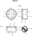
- Fig. 2 shows the cap 12 and its holder 28.
- the holder 28 is an integral part of the cap 12.
- the interior body of the hollow body 14 of the cap 12 is of cylindrical shape.
- the cuts A-A and B-B of Fig. 2 show cap 12 and its holder 28 integrally formed, wherein the perspective view of Fig. 2 shows holder 28 as a separate part. Cuts A-A and B-B of Fig. 2 show the first cap opening 16 which is partially closed by holder 28 so that only a smaller portion, referred to as holder opening 30, of the first cap opening 16 remains open and across which a heating element may extend.
- Fig. 3 shows the holder 28 formed as a separate part of cap 12, wherein the heating element 20 is mounted such that the mesh section 44 of the first mesh density extends across the holder opening 30.
- Fig. 4 shows a mesh 32 of the heating element 20.
- the mesh 32 comprises a mesh section 44 of a first mesh density and, on each of its two extremities, a second mesh section 46 of a second mesh density.
- Fig. 5 shows a mesh strip 42 from which a number of meshes 32 may be die cut.
- Fig. 6 shows a cartridge 40 according to an embodiment of the present invention.
- the cartridge 40 comprises the heater assembly 10 with a cap 12 and a heating element 20 arranged on a holder 28 of the cap 12.
- a transport material piece 26 is arranged in a holder opening 30 of the holder 28.
- a host material piece 24 is arranged in the interior space of the hollow body 14 of the cap 12.
- the cap 12 acts as a rigid housing for the transport material piece 26 and the host material piece 24.
- the cartridge 40 further comprises a liquid storage portion for storing liquid aerosol-forming substrate.
- a retainer 42 is used for retaining the components of the heater assembly 10 and for keeping the heater assembly 10 in contact with the liquid storage portion 36 via the transport material piece 26 and the host material piece 24.
- the cartridge 40 comprises a mouth piece 38 in which the liquid storage portion 36 is arranged.
Priority Applications (1)
| Application Number | Priority Date | Filing Date | Title |
|---|---|---|---|
| PL17732387T PL3487324T3 (pl) | 2016-07-25 | 2017-06-20 | Przepuszczający płyn zespół ogrzewacza z zatyczką |
Applications Claiming Priority (2)
| Application Number | Priority Date | Filing Date | Title |
|---|---|---|---|
| EP16180958 | 2016-07-25 | ||
| PCT/EP2017/065063 WO2018019477A1 (en) | 2016-07-25 | 2017-06-20 | Fluid permeable heater assembly with cap |
Publications (2)
| Publication Number | Publication Date |
|---|---|
| EP3487324A1 EP3487324A1 (en) | 2019-05-29 |
| EP3487324B1 true EP3487324B1 (en) | 2020-11-18 |
Family
ID=56550105
Family Applications (1)
| Application Number | Title | Priority Date | Filing Date |
|---|---|---|---|
| EP17732387.0A Active EP3487324B1 (en) | 2016-07-25 | 2017-06-20 | Fluid permeable heater assembly with cap |
Country Status (19)
| Country | Link |
|---|---|
| EP (1) | EP3487324B1 (ru) |
| JP (3) | JP7002532B2 (ru) |
| KR (3) | KR102527219B1 (ru) |
| CN (2) | CN109475192B (ru) |
| AR (1) | AR109143A1 (ru) |
| AU (1) | AU2017304189A1 (ru) |
| CA (1) | CA3027816A1 (ru) |
| ES (1) | ES2839773T3 (ru) |
| HU (1) | HUE052797T2 (ru) |
| IL (1) | IL263444B (ru) |
| MX (1) | MX2019000716A (ru) |
| MY (1) | MY190163A (ru) |
| PH (1) | PH12018502504A1 (ru) |
| PL (1) | PL3487324T3 (ru) |
| RU (1) | RU2731921C2 (ru) |
| SG (1) | SG11201811597WA (ru) |
| TW (1) | TW201803470A (ru) |
| UA (1) | UA125255C2 (ru) |
| WO (1) | WO2018019477A1 (ru) |
Cited By (2)
| Publication number | Priority date | Publication date | Assignee | Title |
|---|---|---|---|---|
| EP4221460A1 (en) * | 2022-01-30 | 2023-08-02 | Shenzhen Smiss Technology Co. Ltd | Heating assembly, atomizer and electronic cigarette |
| US11730199B2 (en) | 2018-06-07 | 2023-08-22 | Juul Labs, Inc. | Cartridges for vaporizer devices |
Families Citing this family (11)
| Publication number | Priority date | Publication date | Assignee | Title |
|---|---|---|---|---|
| US10327477B2 (en) | 2016-07-25 | 2019-06-25 | Altria Client Services Llc | Cartridge for an aerosol-generating system with heater protection |
| US11259370B2 (en) | 2017-12-08 | 2022-02-22 | Altria Client Services Llc | Multi-component aerosol-generating device with impact absorbing part |
| KR20210016361A (ko) | 2018-05-31 | 2021-02-15 | 필립모리스 프로덕츠 에스.에이. | 천공된 이송 물질을 구비한 히터 조립체 |
| CN113873904A (zh) * | 2019-05-06 | 2021-12-31 | 进立有限公司 | 微型蒸发器的筒体和平板加热元件的装配结构 |
| US20220295889A1 (en) * | 2019-06-25 | 2022-09-22 | Philip Morris Products S.A. | An aerosol-generating system and a cartridge for an aerosol-generating system having particulate filter |
| KR102399212B1 (ko) * | 2020-01-31 | 2022-05-17 | 주식회사 케이티앤지 | 증기화기 및 이를 포함하는 에어로졸 발생 장치 |
| WO2021258286A1 (zh) * | 2020-06-23 | 2021-12-30 | 深圳市华诚达精密工业有限公司 | 框体式发热组件、发热单元以及雾化系统 |
| KR102511597B1 (ko) * | 2020-09-07 | 2023-03-17 | 주식회사 케이티앤지 | 에어로졸 생성 장치 및 에어로졸 생성 장치에 사용되는 카트리지 |
| EP4218360A1 (en) * | 2020-09-23 | 2023-08-02 | Philip Morris Products S.A. | A heating element having increased resistance |
| KR20230133968A (ko) * | 2021-01-20 | 2023-09-19 | 썬전 화청다 프리시젼 인더스트리 컴퍼니 리미티드 | 고강도 무화 어셈블리 및 무화 장치 |
| WO2023047278A1 (en) * | 2021-09-21 | 2023-03-30 | Jt International Sa | A refilling station for a capsule or cartridge for electronic cigarettes |
Citations (12)
| Publication number | Priority date | Publication date | Assignee | Title |
|---|---|---|---|---|
| US20050086830A1 (en) | 2003-10-24 | 2005-04-28 | Zukor Kenneth S. | Processing cap assembly for isolating contents of a container |
| WO2010045371A1 (en) | 2008-10-15 | 2010-04-22 | Gilead Palo Alto, Inc. | Pyrido- and pyrimido (1, 2-a) pyrimidine compounds useful as stearoyl coa desaturase inhibitors |
| US20130213419A1 (en) | 2012-02-22 | 2013-08-22 | Altria Client Services Inc. | Electronic smoking article and improved heater element |
| US20140109921A1 (en) | 2012-09-29 | 2014-04-24 | Shenzhen Smoore Technology Limited | Electronic cigarette |
| US20140202454A1 (en) | 2011-07-27 | 2014-07-24 | Batmark Limited | Inhaler component |
| CN203986096U (zh) | 2014-04-03 | 2014-12-10 | 惠州市吉瑞科技有限公司 | 一种雾化器以及电子烟 |
| WO2015117705A2 (en) | 2014-02-10 | 2015-08-13 | Philip Morris Products S.A. | Cartridge for an aerosol-generating system |
| WO2015117701A1 (en) | 2014-02-10 | 2015-08-13 | Philip Morris Products S.A. | Fluid permeable heater assembly for an aerosol-generating system and method for assembling a fluid permeable heater for an aerosol-generating system |
| WO2015117704A1 (en) | 2014-02-10 | 2015-08-13 | Philip Morris Products S.A. | An aerosol-generating system having a heater assembly and a cartridge for an aerosol-generating system having a fluid permeable heater assembly |
| US20160007655A1 (en) | 2014-07-11 | 2016-01-14 | Shenzhen First Union Technology Co., Ltd. | Atomizer and electronic cigarette having same |
| WO2016092261A1 (en) | 2014-12-11 | 2016-06-16 | Nicoventures Holdings Limited | Aerosol provision systems |
| WO2016096497A1 (en) | 2014-12-15 | 2016-06-23 | Philip Morris Products S.A. | An aerosol-generating system using the venturi effect to deliver substrate to a heating element |
Family Cites Families (11)
| Publication number | Priority date | Publication date | Assignee | Title |
|---|---|---|---|---|
| IL291500B2 (en) | 2011-08-16 | 2024-03-01 | Juul Labs Inc | Low temperature electronic evaporation device and methods |
| GB2504076A (en) | 2012-07-16 | 2014-01-22 | Nicoventures Holdings Ltd | Electronic smoking device |
| CA2886395C (en) * | 2012-12-28 | 2020-10-27 | Philip Morris Products S.A. | Heating assembly for an aerosol generating system |
| UA119551C2 (uk) | 2014-02-10 | 2019-07-10 | Філіп Морріс Продактс С.А. | Нагрівальний вузол для системи, що генерує аерозоль |
| KR102650793B1 (ko) | 2014-02-10 | 2024-03-26 | 필립모리스 프로덕츠 에스.에이. | 유체 투과성 히터 조립체를 구비한 에어로졸 발생 시스템 |
| EP3104720A1 (en) | 2014-02-10 | 2016-12-21 | Philip Morris Products S.A. | An aerosol-generating system comprising a device and a cartridge, in which the device ensures electrical contact with the cartridge |
| US20150335070A1 (en) | 2014-05-20 | 2015-11-26 | R.J. Reynolds Tobacco Company | Electrically-powered aerosol delivery system |
| US10327475B2 (en) | 2014-12-15 | 2019-06-25 | Philip Morris Products S.A. | Continuous mode heater assembly for aerosol-generating system |
| TWI674071B (zh) | 2014-12-15 | 2019-10-11 | 瑞士商菲利浦莫里斯製品股份有限公司 | 氣溶膠產生系統及用於在電熱式氣溶膠產生系統內導引氣流的方法 |
| AR103016A1 (es) | 2014-12-15 | 2017-04-12 | Philip Morris Products Sa | Sistemas generadores de aerosol y métodos para dirigir un flujo de aire hacia dentro de un sistema generador de aerosol calentado eléctricamente |
| EP2921065A1 (en) * | 2015-03-31 | 2015-09-23 | Philip Morris Products S.a.s. | Extended heating and heating assembly for an aerosol generating system |
-
2017
- 2017-06-20 AU AU2017304189A patent/AU2017304189A1/en not_active Abandoned
- 2017-06-20 KR KR1020197001467A patent/KR102527219B1/ko active IP Right Grant
- 2017-06-20 RU RU2019104874A patent/RU2731921C2/ru active
- 2017-06-20 EP EP17732387.0A patent/EP3487324B1/en active Active
- 2017-06-20 HU HUE17732387A patent/HUE052797T2/hu unknown
- 2017-06-20 MY MYPI2018002198A patent/MY190163A/en unknown
- 2017-06-20 MX MX2019000716A patent/MX2019000716A/es unknown
- 2017-06-20 WO PCT/EP2017/065063 patent/WO2018019477A1/en unknown
- 2017-06-20 ES ES17732387T patent/ES2839773T3/es active Active
- 2017-06-20 CA CA3027816A patent/CA3027816A1/en not_active Abandoned
- 2017-06-20 CN CN201780043496.2A patent/CN109475192B/zh active Active
- 2017-06-20 JP JP2019503906A patent/JP7002532B2/ja active Active
- 2017-06-20 UA UAA201811731A patent/UA125255C2/uk unknown
- 2017-06-20 PL PL17732387T patent/PL3487324T3/pl unknown
- 2017-06-20 SG SG11201811597WA patent/SG11201811597WA/en unknown
- 2017-06-20 KR KR1020247009332A patent/KR20240042199A/ko active Search and Examination
- 2017-06-20 KR KR1020237014077A patent/KR102650939B1/ko active IP Right Grant
- 2017-06-20 IL IL263444A patent/IL263444B/en unknown
- 2017-06-20 CN CN202210636505.1A patent/CN114983033A/zh active Pending
- 2017-07-18 TW TW106123911A patent/TW201803470A/zh unknown
- 2017-07-24 AR ARP170102074A patent/AR109143A1/es unknown
-
2018
- 2018-11-27 PH PH12018502504A patent/PH12018502504A1/en unknown
-
2021
- 2021-12-27 JP JP2021212539A patent/JP2022043242A/ja active Pending
-
2023
- 2023-12-28 JP JP2023222560A patent/JP2024029154A/ja active Pending
Patent Citations (12)
| Publication number | Priority date | Publication date | Assignee | Title |
|---|---|---|---|---|
| US20050086830A1 (en) | 2003-10-24 | 2005-04-28 | Zukor Kenneth S. | Processing cap assembly for isolating contents of a container |
| WO2010045371A1 (en) | 2008-10-15 | 2010-04-22 | Gilead Palo Alto, Inc. | Pyrido- and pyrimido (1, 2-a) pyrimidine compounds useful as stearoyl coa desaturase inhibitors |
| US20140202454A1 (en) | 2011-07-27 | 2014-07-24 | Batmark Limited | Inhaler component |
| US20130213419A1 (en) | 2012-02-22 | 2013-08-22 | Altria Client Services Inc. | Electronic smoking article and improved heater element |
| US20140109921A1 (en) | 2012-09-29 | 2014-04-24 | Shenzhen Smoore Technology Limited | Electronic cigarette |
| WO2015117705A2 (en) | 2014-02-10 | 2015-08-13 | Philip Morris Products S.A. | Cartridge for an aerosol-generating system |
| WO2015117701A1 (en) | 2014-02-10 | 2015-08-13 | Philip Morris Products S.A. | Fluid permeable heater assembly for an aerosol-generating system and method for assembling a fluid permeable heater for an aerosol-generating system |
| WO2015117704A1 (en) | 2014-02-10 | 2015-08-13 | Philip Morris Products S.A. | An aerosol-generating system having a heater assembly and a cartridge for an aerosol-generating system having a fluid permeable heater assembly |
| CN203986096U (zh) | 2014-04-03 | 2014-12-10 | 惠州市吉瑞科技有限公司 | 一种雾化器以及电子烟 |
| US20160007655A1 (en) | 2014-07-11 | 2016-01-14 | Shenzhen First Union Technology Co., Ltd. | Atomizer and electronic cigarette having same |
| WO2016092261A1 (en) | 2014-12-11 | 2016-06-16 | Nicoventures Holdings Limited | Aerosol provision systems |
| WO2016096497A1 (en) | 2014-12-15 | 2016-06-23 | Philip Morris Products S.A. | An aerosol-generating system using the venturi effect to deliver substrate to a heating element |
Cited By (2)
| Publication number | Priority date | Publication date | Assignee | Title |
|---|---|---|---|---|
| US11730199B2 (en) | 2018-06-07 | 2023-08-22 | Juul Labs, Inc. | Cartridges for vaporizer devices |
| EP4221460A1 (en) * | 2022-01-30 | 2023-08-02 | Shenzhen Smiss Technology Co. Ltd | Heating assembly, atomizer and electronic cigarette |
Also Published As
| Publication number | Publication date |
|---|---|
| IL263444B (en) | 2022-08-01 |
| KR20230058560A (ko) | 2023-05-03 |
| JP7002532B2 (ja) | 2022-01-20 |
| PH12018502504A1 (en) | 2019-07-29 |
| CN109475192B (zh) | 2022-06-28 |
| KR102650939B1 (ko) | 2024-03-26 |
| AU2017304189A1 (en) | 2019-01-24 |
| WO2018019477A1 (en) | 2018-02-01 |
| ES2839773T3 (es) | 2021-07-05 |
| CA3027816A1 (en) | 2018-02-01 |
| TW201803470A (zh) | 2018-02-01 |
| RU2731921C2 (ru) | 2020-09-09 |
| RU2019104874A3 (ru) | 2020-08-25 |
| CN114983033A (zh) | 2022-09-02 |
| JP2024029154A (ja) | 2024-03-05 |
| MX2019000716A (es) | 2019-06-10 |
| EP3487324A1 (en) | 2019-05-29 |
| BR112018077417A2 (pt) | 2019-04-09 |
| IL263444A (en) | 2019-01-31 |
| SG11201811597WA (en) | 2019-02-27 |
| UA125255C2 (uk) | 2022-02-09 |
| KR20190034198A (ko) | 2019-04-01 |
| MY190163A (en) | 2022-03-31 |
| KR102527219B1 (ko) | 2023-05-02 |
| CN109475192A (zh) | 2019-03-15 |
| PL3487324T3 (pl) | 2021-05-31 |
| JP2022043242A (ja) | 2022-03-15 |
| KR20240042199A (ko) | 2024-04-01 |
| AR109143A1 (es) | 2018-10-31 |
| JP2019524114A (ja) | 2019-09-05 |
| HUE052797T2 (hu) | 2021-05-28 |
| RU2019104874A (ru) | 2020-08-25 |
Similar Documents
| Publication | Publication Date | Title |
|---|---|---|
| EP3487324B1 (en) | Fluid permeable heater assembly with cap | |
| US11933454B2 (en) | Fluid permeable heater assembly with cap | |
| EP3585190B1 (en) | Moulded mounting for an aerosol-generating element in an aerosol-generating system | |
| EP3487325B1 (en) | Cartridge for an aerosol-generating system with heater protection | |
| CA2937974C (en) | An aerosol-generating system comprising a device and a cartridge, in which the device ensures electrical contact with the cartridge | |
| EP3104724B1 (en) | An aerosol-generating system having a heater assembly and a cartridge for an aerosol-generating system having a fluid permeable heater assembly | |
| EP3487323B1 (en) | Manufacturing a fluid permeable heater assembly with cap | |
| BR112018077417B1 (pt) | Conjunto aquecedor permeável a fluido para um sistema gerador de aerossol, cartucho para um sistema gerador de aerossol e cartucho para um sistema gerador de aerossol |
Legal Events
| Date | Code | Title | Description |
|---|---|---|---|
| STAA | Information on the status of an ep patent application or granted ep patent |
Free format text: STATUS: UNKNOWN |
|
| STAA | Information on the status of an ep patent application or granted ep patent |
Free format text: STATUS: THE INTERNATIONAL PUBLICATION HAS BEEN MADE |
|
| PUAI | Public reference made under article 153(3) epc to a published international application that has entered the european phase |
Free format text: ORIGINAL CODE: 0009012 |
|
| STAA | Information on the status of an ep patent application or granted ep patent |
Free format text: STATUS: REQUEST FOR EXAMINATION WAS MADE |
|
| 17P | Request for examination filed |
Effective date: 20190201 |
|
| AK | Designated contracting states |
Kind code of ref document: A1 Designated state(s): AL AT BE BG CH CY CZ DE DK EE ES FI FR GB GR HR HU IE IS IT LI LT LU LV MC MK MT NL NO PL PT RO RS SE SI SK SM TR |
|
| AX | Request for extension of the european patent |
Extension state: BA ME |
|
| DAV | Request for validation of the european patent (deleted) | ||
| DAX | Request for extension of the european patent (deleted) | ||
| REG | Reference to a national code |
Ref country code: HK Ref legal event code: DE Ref document number: 40005076 Country of ref document: HK |
|
| GRAP | Despatch of communication of intention to grant a patent |
Free format text: ORIGINAL CODE: EPIDOSNIGR1 |
|
| STAA | Information on the status of an ep patent application or granted ep patent |
Free format text: STATUS: GRANT OF PATENT IS INTENDED |
|
| INTG | Intention to grant announced |
Effective date: 20200617 |
|
| GRAS | Grant fee paid |
Free format text: ORIGINAL CODE: EPIDOSNIGR3 |
|
| GRAA | (expected) grant |
Free format text: ORIGINAL CODE: 0009210 |
|
| STAA | Information on the status of an ep patent application or granted ep patent |
Free format text: STATUS: THE PATENT HAS BEEN GRANTED |
|
| AK | Designated contracting states |
Kind code of ref document: B1 Designated state(s): AL AT BE BG CH CY CZ DE DK EE ES FI FR GB GR HR HU IE IS IT LI LT LU LV MC MK MT NL NO PL PT RO RS SE SI SK SM TR |
|
| REG | Reference to a national code |
Ref country code: GB Ref legal event code: FG4D |
|
| REG | Reference to a national code |
Ref country code: CH Ref legal event code: EP |
|
| REG | Reference to a national code |
Ref country code: DE Ref legal event code: R096 Ref document number: 602017027779 Country of ref document: DE |
|
| REG | Reference to a national code |
Ref country code: IE Ref legal event code: FG4D |
|
| REG | Reference to a national code |
Ref country code: AT Ref legal event code: REF Ref document number: 1334775 Country of ref document: AT Kind code of ref document: T Effective date: 20201215 |
|
| REG | Reference to a national code |
Ref country code: RO Ref legal event code: EPE |
|
| REG | Reference to a national code |
Ref country code: NL Ref legal event code: FP |
|
| REG | Reference to a national code |
Ref country code: SK Ref legal event code: T3 Ref document number: E 35944 Country of ref document: SK |
|
| REG | Reference to a national code |
Ref country code: CH Ref legal event code: NV Representative=s name: VENI GMBH, CH |
|
| REG | Reference to a national code |
Ref country code: SE Ref legal event code: TRGR |
|
| REG | Reference to a national code |
Ref country code: AT Ref legal event code: MK05 Ref document number: 1334775 Country of ref document: AT Kind code of ref document: T Effective date: 20201118 |
|
| REG | Reference to a national code |
Ref country code: GR Ref legal event code: EP Ref document number: 20210400425 Country of ref document: GR Effective date: 20210416 |
|
| PG25 | Lapsed in a contracting state [announced via postgrant information from national office to epo] |
Ref country code: FI Free format text: LAPSE BECAUSE OF FAILURE TO SUBMIT A TRANSLATION OF THE DESCRIPTION OR TO PAY THE FEE WITHIN THE PRESCRIBED TIME-LIMIT Effective date: 20201118 Ref country code: NO Free format text: LAPSE BECAUSE OF FAILURE TO SUBMIT A TRANSLATION OF THE DESCRIPTION OR TO PAY THE FEE WITHIN THE PRESCRIBED TIME-LIMIT Effective date: 20210218 Ref country code: RS Free format text: LAPSE BECAUSE OF FAILURE TO SUBMIT A TRANSLATION OF THE DESCRIPTION OR TO PAY THE FEE WITHIN THE PRESCRIBED TIME-LIMIT Effective date: 20201118 Ref country code: PT Free format text: LAPSE BECAUSE OF FAILURE TO SUBMIT A TRANSLATION OF THE DESCRIPTION OR TO PAY THE FEE WITHIN THE PRESCRIBED TIME-LIMIT Effective date: 20210318 |
|
| REG | Reference to a national code |
Ref country code: HU Ref legal event code: AG4A Ref document number: E052797 Country of ref document: HU |
|
| PG25 | Lapsed in a contracting state [announced via postgrant information from national office to epo] |
Ref country code: AT Free format text: LAPSE BECAUSE OF FAILURE TO SUBMIT A TRANSLATION OF THE DESCRIPTION OR TO PAY THE FEE WITHIN THE PRESCRIBED TIME-LIMIT Effective date: 20201118 Ref country code: BG Free format text: LAPSE BECAUSE OF FAILURE TO SUBMIT A TRANSLATION OF THE DESCRIPTION OR TO PAY THE FEE WITHIN THE PRESCRIBED TIME-LIMIT Effective date: 20210218 Ref country code: LV Free format text: LAPSE BECAUSE OF FAILURE TO SUBMIT A TRANSLATION OF THE DESCRIPTION OR TO PAY THE FEE WITHIN THE PRESCRIBED TIME-LIMIT Effective date: 20201118 Ref country code: IS Free format text: LAPSE BECAUSE OF FAILURE TO SUBMIT A TRANSLATION OF THE DESCRIPTION OR TO PAY THE FEE WITHIN THE PRESCRIBED TIME-LIMIT Effective date: 20210318 |
|
| REG | Reference to a national code |
Ref country code: LT Ref legal event code: MG9D |
|
| PG25 | Lapsed in a contracting state [announced via postgrant information from national office to epo] |
Ref country code: HR Free format text: LAPSE BECAUSE OF FAILURE TO SUBMIT A TRANSLATION OF THE DESCRIPTION OR TO PAY THE FEE WITHIN THE PRESCRIBED TIME-LIMIT Effective date: 20201118 |
|
| REG | Reference to a national code |
Ref country code: ES Ref legal event code: FG2A Ref document number: 2839773 Country of ref document: ES Kind code of ref document: T3 Effective date: 20210705 |
|
| PG25 | Lapsed in a contracting state [announced via postgrant information from national office to epo] |
Ref country code: EE Free format text: LAPSE BECAUSE OF FAILURE TO SUBMIT A TRANSLATION OF THE DESCRIPTION OR TO PAY THE FEE WITHIN THE PRESCRIBED TIME-LIMIT Effective date: 20201118 Ref country code: LT Free format text: LAPSE BECAUSE OF FAILURE TO SUBMIT A TRANSLATION OF THE DESCRIPTION OR TO PAY THE FEE WITHIN THE PRESCRIBED TIME-LIMIT Effective date: 20201118 Ref country code: SM Free format text: LAPSE BECAUSE OF FAILURE TO SUBMIT A TRANSLATION OF THE DESCRIPTION OR TO PAY THE FEE WITHIN THE PRESCRIBED TIME-LIMIT Effective date: 20201118 |
|
| REG | Reference to a national code |
Ref country code: DE Ref legal event code: R026 Ref document number: 602017027779 Country of ref document: DE |
|
| PLBI | Opposition filed |
Free format text: ORIGINAL CODE: 0009260 |
|
| PG25 | Lapsed in a contracting state [announced via postgrant information from national office to epo] |
Ref country code: DK Free format text: LAPSE BECAUSE OF FAILURE TO SUBMIT A TRANSLATION OF THE DESCRIPTION OR TO PAY THE FEE WITHIN THE PRESCRIBED TIME-LIMIT Effective date: 20201118 |
|
| PLAX | Notice of opposition and request to file observation + time limit sent |
Free format text: ORIGINAL CODE: EPIDOSNOBS2 |
|
| 26 | Opposition filed |
Opponent name: NICOVENTURES TRADING LIMITED Effective date: 20210817 |
|
| PG25 | Lapsed in a contracting state [announced via postgrant information from national office to epo] |
Ref country code: AL Free format text: LAPSE BECAUSE OF FAILURE TO SUBMIT A TRANSLATION OF THE DESCRIPTION OR TO PAY THE FEE WITHIN THE PRESCRIBED TIME-LIMIT Effective date: 20201118 |
|
| PG25 | Lapsed in a contracting state [announced via postgrant information from national office to epo] |
Ref country code: SI Free format text: LAPSE BECAUSE OF FAILURE TO SUBMIT A TRANSLATION OF THE DESCRIPTION OR TO PAY THE FEE WITHIN THE PRESCRIBED TIME-LIMIT Effective date: 20201118 |
|
| PLBB | Reply of patent proprietor to notice(s) of opposition received |
Free format text: ORIGINAL CODE: EPIDOSNOBS3 |
|
| REG | Reference to a national code |
Ref country code: SE Ref legal event code: EUG |
|
| PG25 | Lapsed in a contracting state [announced via postgrant information from national office to epo] |
Ref country code: CZ Free format text: LAPSE BECAUSE OF NON-PAYMENT OF DUE FEES Effective date: 20210620 Ref country code: MC Free format text: LAPSE BECAUSE OF FAILURE TO SUBMIT A TRANSLATION OF THE DESCRIPTION OR TO PAY THE FEE WITHIN THE PRESCRIBED TIME-LIMIT Effective date: 20201118 |
|
| REG | Reference to a national code |
Ref country code: SK Ref legal event code: MM4A Ref document number: E 35944 Country of ref document: SK Effective date: 20210620 |
|
| REG | Reference to a national code |
Ref country code: BE Ref legal event code: MM Effective date: 20210630 |
|
| PG25 | Lapsed in a contracting state [announced via postgrant information from national office to epo] |
Ref country code: LU Free format text: LAPSE BECAUSE OF NON-PAYMENT OF DUE FEES Effective date: 20210620 |
|
| PG25 | Lapsed in a contracting state [announced via postgrant information from national office to epo] |
Ref country code: IE Free format text: LAPSE BECAUSE OF NON-PAYMENT OF DUE FEES Effective date: 20210620 Ref country code: HU Free format text: LAPSE BECAUSE OF NON-PAYMENT OF DUE FEES Effective date: 20210621 |
|
| PG25 | Lapsed in a contracting state [announced via postgrant information from national office to epo] |
Ref country code: IS Free format text: LAPSE BECAUSE OF FAILURE TO SUBMIT A TRANSLATION OF THE DESCRIPTION OR TO PAY THE FEE WITHIN THE PRESCRIBED TIME-LIMIT Effective date: 20210318 Ref country code: SK Free format text: LAPSE BECAUSE OF NON-PAYMENT OF DUE FEES Effective date: 20210620 Ref country code: SE Free format text: LAPSE BECAUSE OF NON-PAYMENT OF DUE FEES Effective date: 20210621 Ref country code: GR Free format text: LAPSE BECAUSE OF NON-PAYMENT OF DUE FEES Effective date: 20220105 |
|
| PG25 | Lapsed in a contracting state [announced via postgrant information from national office to epo] |
Ref country code: BE Free format text: LAPSE BECAUSE OF NON-PAYMENT OF DUE FEES Effective date: 20210630 |
|
| PG25 | Lapsed in a contracting state [announced via postgrant information from national office to epo] |
Ref country code: CY Free format text: LAPSE BECAUSE OF FAILURE TO SUBMIT A TRANSLATION OF THE DESCRIPTION OR TO PAY THE FEE WITHIN THE PRESCRIBED TIME-LIMIT Effective date: 20201118 |
|
| P01 | Opt-out of the competence of the unified patent court (upc) registered |
Effective date: 20230529 |
|
| PGFP | Annual fee paid to national office [announced via postgrant information from national office to epo] |
Ref country code: RO Payment date: 20230608 Year of fee payment: 7 Ref country code: NL Payment date: 20230620 Year of fee payment: 7 Ref country code: FR Payment date: 20230628 Year of fee payment: 7 Ref country code: DE Payment date: 20230620 Year of fee payment: 7 |
|
| PGFP | Annual fee paid to national office [announced via postgrant information from national office to epo] |
Ref country code: PL Payment date: 20230619 Year of fee payment: 7 |
|
| PGFP | Annual fee paid to national office [announced via postgrant information from national office to epo] |
Ref country code: IT Payment date: 20230621 Year of fee payment: 7 Ref country code: GB Payment date: 20230622 Year of fee payment: 7 Ref country code: ES Payment date: 20230830 Year of fee payment: 7 Ref country code: CH Payment date: 20230702 Year of fee payment: 7 |
|
| PG25 | Lapsed in a contracting state [announced via postgrant information from national office to epo] |
Ref country code: MK Free format text: LAPSE BECAUSE OF FAILURE TO SUBMIT A TRANSLATION OF THE DESCRIPTION OR TO PAY THE FEE WITHIN THE PRESCRIBED TIME-LIMIT Effective date: 20201118 |