EP3487284B1 - Verfahren und sämaschine zum säen von einzelnem saatgut an einer saatstelle - Google Patents
Verfahren und sämaschine zum säen von einzelnem saatgut an einer saatstelle Download PDFInfo
- Publication number
- EP3487284B1 EP3487284B1 EP17755272.6A EP17755272A EP3487284B1 EP 3487284 B1 EP3487284 B1 EP 3487284B1 EP 17755272 A EP17755272 A EP 17755272A EP 3487284 B1 EP3487284 B1 EP 3487284B1
- Authority
- EP
- European Patent Office
- Prior art keywords
- seed
- opening
- conveyor
- seeds
- location
- Prior art date
- Legal status (The legal status is an assumption and is not a legal conclusion. Google has not performed a legal analysis and makes no representation as to the accuracy of the status listed.)
- Active
Links
- 0 CCCCC1CCC(CC2C*(C3)CC3CCCC2)CC1 Chemical compound CCCCC1CCC(CC2C*(C3)CC3CCCC2)CC1 0.000 description 2
Images




Classifications
-
- A—HUMAN NECESSITIES
- A01—AGRICULTURE; FORESTRY; ANIMAL HUSBANDRY; HUNTING; TRAPPING; FISHING
- A01G—HORTICULTURE; CULTIVATION OF VEGETABLES, FLOWERS, RICE, FRUIT, VINES, HOPS OR SEAWEED; FORESTRY; WATERING
- A01G9/00—Cultivation in receptacles, forcing-frames or greenhouses; Edging for beds, lawn or the like
- A01G9/08—Devices for filling-up flower-pots or pots for seedlings; Devices for setting plants or seeds in pots
- A01G9/085—Devices for setting seeds in pots
-
- A—HUMAN NECESSITIES
- A01—AGRICULTURE; FORESTRY; ANIMAL HUSBANDRY; HUNTING; TRAPPING; FISHING
- A01G—HORTICULTURE; CULTIVATION OF VEGETABLES, FLOWERS, RICE, FRUIT, VINES, HOPS OR SEAWEED; FORESTRY; WATERING
- A01G9/00—Cultivation in receptacles, forcing-frames or greenhouses; Edging for beds, lawn or the like
- A01G9/08—Devices for filling-up flower-pots or pots for seedlings; Devices for setting plants or seeds in pots
-
- A—HUMAN NECESSITIES
- A01—AGRICULTURE; FORESTRY; ANIMAL HUSBANDRY; HUNTING; TRAPPING; FISHING
- A01C—PLANTING; SOWING; FERTILISING
- A01C1/00—Apparatus, or methods of use thereof, for testing or treating seed, roots, or the like, prior to sowing or planting
- A01C1/04—Arranging seed on carriers, e.g. on tapes, on cords ; Carrier compositions
- A01C2001/048—Machines
-
- B—PERFORMING OPERATIONS; TRANSPORTING
- B07—SEPARATING SOLIDS FROM SOLIDS; SORTING
- B07C—POSTAL SORTING; SORTING INDIVIDUAL ARTICLES, OR BULK MATERIAL FIT TO BE SORTED PIECE-MEAL, e.g. BY PICKING
- B07C5/00—Sorting according to a characteristic or feature of the articles or material being sorted, e.g. by control effected by devices which detect or measure such characteristic or feature; Sorting by manually actuated devices, e.g. switches
- B07C5/34—Sorting according to other particular properties
- B07C5/342—Sorting according to other particular properties according to optical properties, e.g. colour
- B07C5/3422—Sorting according to other particular properties according to optical properties, e.g. colour using video scanning devices, e.g. TV-cameras
-
- B—PERFORMING OPERATIONS; TRANSPORTING
- B07—SEPARATING SOLIDS FROM SOLIDS; SORTING
- B07C—POSTAL SORTING; SORTING INDIVIDUAL ARTICLES, OR BULK MATERIAL FIT TO BE SORTED PIECE-MEAL, e.g. BY PICKING
- B07C5/00—Sorting according to a characteristic or feature of the articles or material being sorted, e.g. by control effected by devices which detect or measure such characteristic or feature; Sorting by manually actuated devices, e.g. switches
- B07C5/34—Sorting according to other particular properties
- B07C5/342—Sorting according to other particular properties according to optical properties, e.g. colour
- B07C5/3425—Sorting according to other particular properties according to optical properties, e.g. colour of granular material, e.g. ore particles, grain
Definitions
- the present invention relates to a method for sowing an individual seed in a seed location and to a seeder therefor.
- the seed location is generally a respective compartment of a seed tray having a plurality of tray compartments, each filled with a growth substrate such as soil.
- a growth substrate such as soil.
- One seed is to be sown in each tray compartment.
- sow individual seeds in respective tray compartment of a seed tray by mechanised sowing methods.
- mechanised methods for sowing an individual seed in a tray compartment an individual seed is arranged adjacent to an opening of a tray compartment while being held by vacuum on the tip of a needle of a so-called needle seeder.
- the tip of the needle of such needle seeder is provided with an air opening against which the individual seed is held by the vacuum.
- the seed is released from the tip of the needle, generally by releasing the vacuum and blowing the seed from the tip of the needle into the tray compartment by blowing air through the air opening after releasing the vacuum.
- these known mechanised methods require that the size and shape of the air opening and of the surface around the air opening against which the seed is held, is adapted to the size and shape of the seeds to be sown.
- the latter requires changing the size and/or shape of the air opening and of the surface around the air opening when another type of seed is to be sown, for instance by exchanging the needle or drum that has an air opening having a size and shape adapted to a first type of seed, with a needle or drum having an air opening of a different size and/or shape adapted to a second type of seed.
- a known solution to these drawbacks is to pellet individual seeds.
- the size and shape of individual seeds can be changed, and thus can be optimized for accurate placement of the individual pelleted seeds on the respective openings of the needle or drum.
- different types of seeds having different shape and size can be provided with a uniform size and shape, such that a needle or a drum having air openings that are adapted to the uniform size and shape of the pelleted seeds, can be used to sow different types of seed without replacement of the needle or drum.
- WO2005/011358A1 discloses a seeding apparatus comprising a seed distribution metering means including a rotating drum with apertures on its periphery and a vacuum generator for generating a suction pressure inside the drum so that seeds are attracted to the apertures.
- An air jet releases metered seeds from the drum along a selected trajectory while unselected seeds follow another trajectory.
- US4,010,778 discloses a method and automatic machine for planting seeds in boxes which insures that uniform and consistent seed distribution will be present in each planted box.
- EP1661631A1 discloses a selector, selecting method.
- a line sensor camera inspects seed aligned in rows on a moving belt. The seed in a row determined to be of a predetermined color is sucked from said row of seed on the moving belt by a corresponding nozzle.
- One of the objects of the present invention is to address at least one of the drawbacks of the known methods for sowing an individual seed in a seed location.
- the present invention provides a method for sowing an individual seed in a seed location, according to claim 1.
- the method according to the invention does not require an air opening in the surface for holding on the seed by vacuum and for blowing the seed into the seed location, such as in known methods.
- an air opening in the surface for holding on the seed by vacuum and for blowing the seed into the seed location, such as in known methods.
- Requiring no air opening in the surface for holding on the seed by vacuum and for transporting the seed into the seed location has the advantage over the known methods that placement of the seed on the surface requires less accuracy.
- the seed is flushed into the opening.
- the seed is flushed over the surface in the direction of the opening by directing the fluid over the surface in the direction of the opening, more in particular by using positive pressure.
- the surface can be shaped independent from the size and shape of the seed, and thus it is not required to adapt the surface to the size and shape of the seeds to be sown. This allows seeds of different size and shape to be sown by means of the method according to the invention without exchanging the surface.
- the method according to the invention can be applied for sowing pelleted seed and bare seeds without exchanging the surface.
- the fluid that according to the present invention is directed over the surface in the direction of the opening for flushing the seed from the surface into the opening is a gas, a liquid, or a combination thereof, for instance a gas having dispersed therein drops of a liquid.
- the fluid is air.
- the surface is a flat surface.
- the feature that the surface is flat has the advantage of reduced influence of the surface on the seed while being arranged on the surface and while being flushed from the surface relative to a surface that is not flat, as well as reduced influence of the surface on the fluid that is directed over the surface.
- the surface is a substantially horizontal surface.
- the surface is a conveyor surface, the seed is conveyed along the opening on the conveyor surface, and the seed is flushed into the opening when the seed is adjacent to the opening.
- the features of this embodiment allow the seed to be placed on the conveyor surface at a location different from the location of the opening and subsequently convey the seed on the conveyor surface to the location of the opening in order to arrange the seed adjacent to the opening.
- the conveyor surface with arranged thereon the seed is conveyed along the opening. This provides control over the location and speed of the seed while its being conveyed from the location where it is arranged on the conveyor surface and the location of the opening.
- the seed is conveyed along the opening on the conveyor surface in a conveying direction; and the fluid is directed transverse to the conveying direction.
- the conveyor surface is a surface of a linear conveyor. More preferably the surface of a conveyor belt.
- the conveyor surface is a surface of a rotary surface, for instance a surface of a rotary table.
- the opening in which the seed is flushed is a selected one of a plurality of openings arranged along the conveyor surface, wherein each opening leads to a respective guide channel that extends to a respective seed location.
- the seed is conveyed on the conveyor surface along the plurality of openings in a conveying direction, and the plurality of openings is arranged in a row that extends parallel to the conveying direction.
- the seed that is flushed into the opening is a selected one of a plurality of seeds.
- the plurality of seeds is arranged in a row of seeds on the surface and conveyed along the opening on or over the surface in a direction parallel to the row.
- the seeds are arranged in a row of individual seeds on the surface by moving the surface with a conveying speed, and arranging a batch of seeds on a shaker conveyor that debouches on the surface, wherein the shaker conveyor is configured to channel the batch of seeds into a flow of seeds having a flow speed that is lower than the conveying speed of the surface.
- the number of seeds in the batch of seeds that is arranged on the shaker conveyor is counted.
- the method further comprises: determining a selection characteristic of each of the plurality of seeds that is arranged on the surface; and selecting the seed to be flushed into the opening at least based on the determined selection characteristic of the seed.
- a seed can be selected on the basis of one or more than one determined selection characteristic.
- Selection characteristics can include any internal or external morphological or physiological characteristic, such as size, shape, colour, chlorophyll content, water content, etc.
- the selection characteristic of each of the plurality of seeds is determined using at least one selection sensor.
- the at least one selection sensor includes a camera, and the selection characteristic is determined by analysing images of the seed on the surface obtained by means of the camera.
- the choice of selection sensor(s) is made based on the selection characteristic(s) used for the selection.
- a camera is for instance particularly suitable for determining external morphological or physiological characteristics such as size, shape, and colour of a seed. Examples of other selection sensors suitable for determining internal morphological or physiological characteristics are X-ray sensors and Terahertz sensors.
- the method comprises: determining the location of the seed on the surface, and flushing the seed from the surface into the opening when it is determined that the seed is adjacent to the opening.
- the location of the seed on the surface is determined using at least one location sensor.
- the at least one location sensor includes a camera, and the location of the seed on the surface is determined by analysing images of the seed on the surface obtained by means of the camera.
- a camera is particularly suitable for determining location of the seed on the surface.
- An example of other location sensors that may be used for determining the location of the seed on the surface includes an infrared sensor.
- the location of the seed on the surface is determined, first the seed is arranged on the surface at a first location and subsequently the surface is moved along the opening so as to arrange the seed at a second location adjacent to the opening. After being arranged on the surface and before reaching the second location, the location of the seed on the surface is determined and associated with the location of the surface relative to the second location. When it is determined that the location of the surface that is associated with the seed is at the second location the seed is flushed from the surface into the opening.
- the seed location is a tray compartment of a seed tray.
- the seeder according to the invention is defined in claim 9.
- the nozzle is in particular a positive pressure nozzle.
- the nozzle is in particular directed in the direction of the opening.
- the seeder further comprises a seed supply for arranging a seed on the surface.
- the surface is substantially flat. Furthermore, preferably, at least when arranged adjacent to the opening, the surface is substantially horizontal.
- the surface is a conveyor surface
- the conveyor surface is configured to be moved along a path
- the at least one opening is arranged adjacent to the path of the conveyor surface.
- the conveyor surface is configured to be conveyed along the opening.
- the conveyor surface is configured to be moved along the path in a conveying direction, and the nozzle is arranged for directing the fluid supplied thereto over the surface transverse to the conveying direction.
- the conveyor surface is a surface of a linear conveyor. More preferably the conveyor surface is the surface of a conveyor belt. Alternatively, the conveyor surface is a surface of a rotary surface, for instance a surface of a rotary table.
- the surface is a conveyor surface
- a plurality of openings is arranged along the path of the conveyor surface, wherein each opening leads to a respective guide channel that extends to a respective seed location.
- the conveyor surface is configured to be moved along the path in a conveying direction, and the plurality of openings is arranged in at least one row that extends parallel to the conveying direction.
- the openings are arranged along opposite edges of the conveyor surface that are parallel to the path of the conveyor surface, wherein preferably the nozzles of the selectively operable fluid supplies associated with the openings are arranged above the conveyor surface in between the opposite edges.
- the seed supply comprises: a shaker conveyor that debouches on the conveyor surface, wherein the shaker conveyor is configured to channel a batch of seeds into a flow of seeds; and a seed distributor configured for batch wise distributing seeds to the shaker conveyor.
- the shaker conveyor is configured to channel the batch of seeds into two flows of seeds debouching on opposite sides of the nozzles.
- the additional feature of this advantageous embodiment is in particular advantageous in combination with the embodiment of the seeder according to the invention wherein openings are arranged along opposite edges of the conveyor surface that are parallel to the path of the conveyor surface and wherein the nozzles of the selectively operable fluid supplies associated with the openings are arranged above the conveyor surface in between the opposite edges.
- the seed supply comprises a shake conveyor
- the seed supply comprises a seed counter arranged and configured for counting the number of seeds in the batch of seeds that is distributed to the shaker conveyor.
- the seed location is a tray compartment of a seed tray
- the seeder comprises a seed tray conveyor, preferably a linear conveyor, that is configured for arranging the tray compartment underneath an outlet of the guide channel.
- a seed 1 is arranged on a surface 3 adjacent to an opening 5 that leads to a guide channel 7 that extends to a seed location that in figure 1 is embodied by a tray compartment 9 of a seed tray.
- the tray compartment 9 holds a growth substrate 11.
- the surface 3 is a flat surface.
- the surface 3 is a substantially horizontal surface.
- the guide channel 7 is provided at its upper end with a perforated slanted guiding wall 13 on the side of the opening 5 opposite the side of the opening 5 where the surface is.
- Preferably side walls that serve as side borders of the opening 5 extend from opposite sides 13.1 , 13.2 of the slanted wall 13 towards the surface 3. In figure 1 such side walls are not shown as they would partly obstruct the view on the seed 1.
- the guide channel 7 has at its lower end an outlet 15.
- the guide channel 7 funnels towards the outlet 15.
- a nozzle 17 is arranged that is connected to a fluid source (not shown) via a selectively operable valve 19.
- the fluid is preferably air and the fluid source preferably a source of compressed air.
- FIG 2 is shown that the seed 1 is flushed from the surface 3 into the opening 5 by directing, using the nozzle 17. a fluid 21 over the surface 3 in the direction of the opening 5.
- the fluid 21 is supplied from the fluid supply to the nozzle 17 after opening the selectively operable valve 19.
- the seed 1 is flushed against the perforated slanted wall 13.
- the fluid 21 exits through the perforations in the perforated slanted wall 13, such that the fluid 21 is not directed down into the guide channel 7.
- the seed 1 is guided by means of the guide channel 7 to the tray compartment 9.
- the seed 1 is directed by means of the perforated slanted wall 13 down into the guide channel 7, where the seed 1 is guided via the funnel-shaped part to the outlet 15 that has an outlet opening 23 under which outlet opening 23 the tray compartment 9 is arranged.
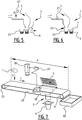
- FIGS 5 and 6 an embodiment of the method according to the invention is shown in which the general steps shown in figures 1 to 3 are used.
- Figure 5 and 6 also show an embodiment of a seeder according to the invention.
- tray compartment 9 is moved in the direction of arrow A and a second tray compartment 25 that is attached thereto is arranged underneath the outlet opening 23 of the guide channel 7. Furthermore, a second seed 27 is arranged on the surface 3 adjacent to the opening 5 as schematically indicated by arrow B. Once the second seed 27 is arranged on the surface 3 and the second tray compartment 25 is arranged underneath the outlet opening 23, the second seed 27 can be sown in the second tray compartment 25 by executing the general steps illustrated in figures 1 to 3 . The above can be repeated with a third, fourth, fifth, ect. tray compartment and seed .
- FIG. 7 an embodiment of the method and the seeder according to the invention is shown that is an advantageous further development of the embodiment illustrated by figures 5 and 6 .
- the surface 3 is a conveyor surface, in particular a surface of a conveyor belt 29.
- the conveyor belt 29 is led over two pulleys 31 , 33 and driven such that the surface thereof moves in the direction of arrow C.
- the conveyor surface 3 is moved along a path P.
- path P is arranged a camera 35 that is arranged above the surface of the conveyor belt 29 such that the surface of the conveyor belt 29 is in its view.
- opening 5 that as shown in figure 1 leads to the guide channel 7 that extends to a seed location that is embodied by a tray compartment 9 of a seed tray.
- the camera 35 is connected to a controller 37.
- the controller 37 is furthermore connected to the selectively operable valve 19.
- a receptacle 39 is arranged.
- seed 1 is placed on the conveyor surface 3 at a location near the start of path P.
- the seed 1 and the conveyor surface 3 are moved together in the direction of arrow C along the path P.
- seed 1 is thus conveyed along the camera 35.
- a second seed 27 is placed on the conveyor surface 3 as schematically illustrated by means of arrow D.
- the camera 35 periodically sends images of the surface of the conveyor belt 29 to the controller 37.
- the controller 37 is provided with a processor that is configured to analyse the images received from the camera 35.
- the processor is configured to detect the seed 1 on the images while seed 1 is conveyed along the camera 35, and to determine a selection characteristic of the seed 1 , for instance the shape of the seed 1.
- the processor is provided with selection criteria for the selection characteristic and is configured to select the seed for flushing into the opening 15 in case the determined selection characteristic meets the selection criteria. In the present case it is determined by the processor that seed 1 meets the selection criteria, and thus seed 1 is selected to be flushed into the opening 5 when seed 1 is arranged adjacent to the opening 5.
- the processor of the controller 37 is furthermore configured to determine the location of the seed 1 relative to the conveyor surface 3 based on the analyses of the images received from the camera 35 and to associate the determined location of the seed 1 relative to the conveyor surface 3 with the location of the conveyor surface 3 relative to the location of the opening 5.
- the controller 37 is connected to an angular rotation sensor 41 that is configured to sense angular rotation of pulley 33.
- the processor of the controller 37 is provided with data regarding the amount of angular rotation of the pulley 33 that is required to move a first location E on the surface of the conveyor belt 29 at a first edge 43 of the view of the camera 35 to a location F adjacent to the opening 15.
- the processor of the controller 37 furthermore is provided with data regarding the amount of angular rotation of the pulley 33 that is required to move a second location G on the surface of the conveyor belt 29 at a second edge 45 of the view of the camera 35 to a location F adjacent to the opening 15.
- the processor of the controller 37 is configured to determine the location H of the seed 1 relative to the locations E and G.
- the processor is configured to calculate based on the above referenced data on the movement of locations E and F and based on the determined location H of the seed 1 relative to the locations E and G, the amount of angular rotation of the pulley 33 that is required to move the location H of the seed 1 on the surface of the conveyor belt 29 to the location F adjacent to the opening 15.
- the processor is configured to determine based on the angular rotation of the pulley 33 sensed by means of the angular rotation sensor 41 when the location H of the seed 1 has arrived at the location F adjacent to the opening 15.
- the processor is configured to control the selectively operable valve 19 such that the valve 19 is opened and fluid 21 is supplied to nozzle 17 for directing the fluid 21 over the conveyor surface 3 in the direction of the opening 15.
- the seed 1 is flushed into the opening 15 and guided into the tray compartment 9 as schematically illustrated by means of arrow I and as described herein above under reference to figures 1 to 4 .
- the tray compartment 9 is moved in the direction of arrow A and a second tray compartment 25 that is attached thereto is arranged underneath the outlet opening 23 of the guide channel 7.
- the processor is configured to store an image of each seed that is detected together with information on whether or not the seed was selected to be flushed into an opening. Also information is advantageously stored regarding the tray compartment in which each selected seed is sown. While seed 1 is conveyed along the opening 15, the second seed 27 is conveyed along camera 35.
- the processor of the controller 37 detects the second seed 27 on the images received from the camera 35 while the second seed 27 is conveyed along the camera 35, and determines a selection characteristic of the seed 27, for instance the shape of the seed 27.
- the processor determines whether the determined selection characteristic meets the selection criteria. In the present case it is determined by the processor that second seed 27 does not meet the selection criteria, and thus second seed 27 is not selected by the processor to be flushed into the opening 5.
- the second seed 27 is conveyed along the opening 5 without being flushed into opening 5.
- the second seed 27 falls into the receptacle 39.
- a shaker conveyor 47 is arranged at the front end 49 of the conveyor belt 29.
- the shaker conveyor 47 debouches on the conveyor surface 3.
- the shaker conveyor 47 is configured to convey a batch 51 of seeds that is arranged on a shaker surface 53 thereof to the end 55 of the shaker conveyor 47 where the shaker conveyor 47 debouches on the conveyor surface 3.
- the shaker surface 53 is mounted on a row of spring elements 57 and is driven by a drive (not shown) such that a shaking movement of the shaker surface 53 is generated that is schematically illustrated by means of the double arrow J.
- the shaking movement J causes a forward movement of the seeds arranged on the shaker surface 53 parallel to the shaker surface 53 schematically illustrated by means of arrow K and the upward movement of the seeds arranged on the shaker surface 53 perpendicular to the shaker surface 53 schematically illustrated by means of arrow L.
- the upward movement L causes seeds that are arrange on top of each other to move way from each other.
- the forward movement K conveys the seeds towards the end 55 of the shaker conveyor 47.
- the shaker surface 53 tapers towards the end 55 of the shaker conveyor 47 such that the batch 51 of seeds is channelled into a flow of seeds that debouches on the conveyor surface 3 in single file.
- the shaker movement is set such that the forward movement K of the seeds that debouch on the conveyor surface 3 is lower than the speed of the conveyor belt 29 in the direction of arrow C.
- a row of individualized seeds 1, 27, 59 is arranged on the conveyor surface 3 and conveyed along the path P in the direction of arrow C along camera 35.
- a fourth seed 61 is about to be arranged on the conveyor surface.
- each seed of the row of seeds is identified by the processor of the controller 37 that is connected to camera 35.
- a selection characteristic is determined by the processor and for each seed the processor determines whether or not the seed meets the selection criteria and is selected to be flushed in the opening 5.
- four openings 5a-d are arranged along the path P.
- Each of the openings 5a-d leads to a respective guide channel 7a-d that extends to a respective seed location embodied by a respective tray compartment 9a-d.
- the processor determines that a seed that is conveyed along the camera 35 meets the selection criteria, the processor selects one of the openings 5a-d as the opening to flush the seed into. Analogous to what is described under reference to figures 9 and 10 , the processor determines the location of the seed on the conveyor surface 3 and determines when the seed is adjacent to the opening that is selected to flush the seed in. In the shown embodiment opening 5d is selected by the processor to flush seed 1 in.
- the processor controls the selectively operable valve 19d such that the valve 19d is opened and fluid is supplied to nozzle 17d for directing the fluid over the conveyor surface 3 in the direction of the opening 5d.
- the seed 1 is then flushed into the opening 5d and guided by means of guide channel 7d into the tray compartment 9d as schematically illustrated by means of anOW I.
- side walls that serve as side borders of the openings 5a, 5b, 5c, 5d preferably extend from opposite sides of each of the slanted walls 13 towards the surface 3. In figure 12 such side walls are not shown. Such side walls provide a separation between neighbouring openings 5, thereby preventing a seed to be flushed not into the selected opening but into a neighbouring opening.
- each tray compartment 9a-d is arranged under a respective guide channel 7a- 7d.
- the processor of the controller 37 selects for each of the selected seeds 1 , 27, 59, 61 a respective one of the openings 15a-d, such that one seed is sown into each one of the tray compartments 9a-d.
- the row 63 of tray compartments 9a-9d is one row of a seed tray 65 having a plurality of parallel rows 63, 67. 69 of tray compartments.
- the seed tray 65 is moved by means of a linear conveyor (not shown) on which the seed tray is arranged in the direction of arrow A, such that a next row 67 with tray compartments 25a-d is arranged under the guide channels 7a-7d, wherein each tray compartment 25a-d is arranged under a respective guide channel 7a-7d.
- a seed is sown that is selected from the continuous flow of individual seeds that is arranged on conveyor surface 3.
- the seed tray 65 is again moved by means of the linear conveyor (not shown) on which the seed tray is arranged in the direction of arrow A, such that a next row 69 with tray compartments is arranged under the guide channels 7a-7d, wherein each tray compartment of row 69 is arranged under a respective guide channel 7a-7d. Subsequently, in each tray compartment of row 69, a seed is sown that is selected from the continuous flow of individual seeds that is arranged on conveyor surface 3.
- opening 5d is selected for seed 1
- opening 5c is selected for seed 27
- opening 5b is selected for seed 59
- opening 5a is selected for seed 61.
- the next seed 71 of the continuous row of seeds that is arranged on the conveyor surface 3, which seed 71 is in figures 12 and 13 arranged on the shaker surface 53, will be located where seed 1 is located in the situation shown in figures 12 and 13 , once seeds 1, 27, 59, and 61 are flushed into the tray compartments 9a-d.
- the time that it takes for the conveyor belt 29 to convey seed 71 to the location f of the opening 5d is available for moving seed tray 65 in the direction of arrow A such that the tray compartments 25a-d of the row 67 are arranged underneath the guide channels 7a-d.
- This allows the conveyor belt 29 to be continuously driven it is noted, that it is for instance possible that the time that is required to move seed tray 65 in the direction of arrow A such that the tray compartments 25a-d of the row 67 are arranged underneath the guide channels 7a-d, is shorter than the time that it takes for the conveyor belt 29 to convey a seed from the location H of seed 1 shown in figures 12 and 13 to location F of the opening 5d.
- openings 5a-d may be selected in another sequence by the processor for subsequent seeds of the continuous row of seeds without having to stop or slow the conveyor belt 29 in order to move seed tray 65 in the direction of arrow A such that the tray compartments of a subsequent row are arranged underneath the guide channels 7a-d.
- the processor of the controller 37 does not select the seed for flushing into one of the openings and allows the seed to fall into the receptacle 39 at the end of path P.
- a first embodiment is shown of a seed distributor 73 that is configured for batch wise distributing seeds to the shaker conveyor 47.
- the seed distributor is arranged above the shaker conveyor 47 of figures 12 and 13 .
- the seed distributor 73 has a container 75 that, as schematically illustrated by means of double arrow L is selectively tiltable around tilting axis 83.
- the container 75 is selectively tiltable by means of a mechanism (not shown) that is controlled by the controller 37.
- the container 75 holds seeds 77.
- a plurality of the seeds held in the container 75 are batch wise arranged on the shaker conveyor surface 53, such that a batch 51 of seeds is arranged on the shaker conveyor 53 that, as described herein above under reference to figures 12 and 13 , is channelled into the flow of seeds that debouches on the conveyor surface 3 in single file.
- the controller 37 is connected to the seed distributor 73 and configured to selectively tilt the container 75 when a batch of seeds is to be arranged on the shaker surface 53.
- a seed counter 79 is arranged such that the seeds that fall out of the container 75 when the container 75 is tilted pass the seed counter 79.
- the seed counter 79 has an opening 81 through which the seeds pass when falling out of the container 75. Along the circumference of the opening 81 light sources and cooperating light sensors are arranged that allow for detecting a single seed that passes the opening 81.
- the seed counter 79 is configured to provide the controller 37 with data on the number of seeds that have passed the seed counter 79. On the basis of the number of seeds that have passed the seed counter 79 and on the basis of data on the number of seeds that have passed the camera 35, the controller 37 is configured to determine at least an indication of the number of seeds that is arranged on the shaker conveyor 47.
- the controller 37 is configured to control the tilting of the container 75 in order to ensure that a proper amount of seeds is arranged on the shaker conveyor 47 to enable proper execution of the sowing process. Both underfilling and overfilling of the shaker conveyor 47 may result in the shaker conveyor to stop functioning or to deliver a flow of seeds on the conveyor surface 3 with a flow velocity that is unsuitable for providing on the conveyor surface 3 a row of individualised seeds.
- the controller 37 is ad vantageously configured to tilt the container 75 and shake seeds out of the container 75 by generating an oscillating tilting motion with a relatively small angular movement around the tilting axis 83.
- the seed container 75 is in an advantageous embodiment arranged on a carrousel on which a plurality of seed containers can be arranged. This makes it possible after sowing seeds from a first container into the tray compartments of a seed tray, to sow seeds from another seed container into the tray compartments of a subsequent seed tray, by rotating the carrousel such that the other seed container is arranged above the shaker surface 53 of the shaker conveyor 47 and by subsequently tilting the other seed container in order to distribute seeds to the shaker surface 53.
- the seeds of the other seed container are of another type, and seeds of the previous type are still arranged on the shaker surface 53 or on the conveyor surface 3, the seeds of the previous type are first conveyed to the receptacle 39 at the end of path P of the conveyor 29 before the seeds of the other type are distributed to the shaker conveyor.
- a system is provided for removing seeds from the receptacle 39.
- a second embodiment is shown of a seed distributor 173 that is configured for batch wise distributing seeds to the first shaker conveyor 47.
- the seed distributor 173 has a second shaker conveyor 174 having an first end 174a arranged above the surface 53 of the first shaker conveyor 47 of figures 12 and 13 .
- the seed distributor 173 furthermore includes a container 175.
- the container 175 is selectively tillable between a first position and a second position.
- the container 175 is selectively tiltable by means of a mechanism (not shown) that is controlled by the controller 37.
- FIG 14 is shown that the container 175 has been tilted from the first position (indicated with dashes) into a second position above a second end 174b of the second shaker conveyor 174, such that all the seeds that were held in the container 175 have been arranged on the surface 176 of the second shaker conveyor 174.
- the shaker surface 176 is mounted on a row of spring elements 157 and is driven by a drive (not shown) controller by controller 37.
- the second shaker conveyor 174 is configured such that a shaking movement of the shaker surface 176, schematically illustrated by means of the double arrow N, can be generated by means of the drive.
- the controller 37 can control the drive such that the shaking movement of the shaker surface 176 is generated.
- the shaking movement N causes a forward movement of the seeds arranged on the shaker surface 176 parallel to the shaker surface 176 schematically illustrated by means of arrow O.
- the forward movement O conveys the seeds towards the first end 174a of the second shaker conveyor 174.
- the seeds fall down onto the surface 53 of the first shaker conveyor 47.
- a seed counter 79 is arranged such that the seeds that fall from the shaker surface 176 pass the seed counter 79.
- the seed counter 79 has an opening 81 through which the seeds pass.
- the seed counter 79 is configured to provide the controller 37 with data on the number of seeds that have passed the seed counter 79. On the basis of the number of seeds that have passed the seed counter 79 and on the basis of data on the number of seeds that have passed the camera 35, the controller 37 is configured to determine at least an indication of the number of seeds that is arranged on the first shaker conveyor 47.
- the controller 37 is configured to control the shaking movement of the shaker surface 176 of the second shaker conveyor 174 in order to ensure that a proper amount of seeds is arranged on the shaker surface 53 of the first shaker conveyor 47 to enable proper execution of the sowing process. Both underfilling and overfilling of the shaker conveyor 47 may result in the shaker conveyor to stop functioning or to deliver a flow of seeds on the conveyor surface 3 with a flow velocity that is unsuitable for providing on the conveyor suriace 3 a row of individualised seeds.
- the controller 37 is advantageously configured to stop the shaking movement of the shaker surface 176 before the number of seeds that is arranged on the first shaker conveyor 47 is such that overfilling occurs and to start the shaking movement of the shaker surface 176 again before underfilling occurs.
- the empty container 175 can be tilted into its first position while the second shaker conveyor 174 is operated to distribute seeds to the first shaker conveyor 47.
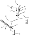
- the shaker surface 176 of the second shaker conveyor 174 can be tilted about a tilt axis 183 in the direction of arrow Q from the position shown in figures 15 and 16 into a position shown in figure 17 .
- This allows to return seeds that are arranged on the shaker surface 176 of the second shaker conveyor 174 into the empty container 175 in the direction of arrow R.
- the seeds are for instance returned into the container 175 when the sowing of seeds in a seed tray is finished and another type of seeds is to be sown in a subsequent seed tray.
- the seed container 175 is in an advantageous embodiment arranged on a carrousel on which a plurality of seed containers can be arranged. This makes it possible after sowing seeds from a first container into the tray compartments of a seed tray, to sow seeds from another seed container into the tray compartments of a subsequent seed tray. To that effect, after returning the seeds into the first container 175, the carrousel is rotated such that the other seed container is arranged at the second shaker conveyor 174. Subsequently the steps described herein above under reference to figure 15 are repeated in order to distribute seeds held in the other container to the shaker conveyor 47.
- the seed distributor 173 shown in figures 15 to 17 allows for all the seeds held in a container 175 to be arranged on the second shaker conveyor 174 before distributing seeds to the first shaker conveyor 47. This has the advantage that the distribution is less selective relative to distribution with the seed distributor 73 shown in figure 14 where seed is distributed directly from the container 75. Being less selective is in particular relevant when the method and seeder according to the invention are used to sow a representative sample of a batch of seeds.
- openings 5a, 5b, 5c, and 5d are arranged along a first longitudinal edge 85 of the conveyor belt 28, which first edge extends parallel to the path P of the conveyor belt 29. Furthermore, along the second longitudinal edge 86 opposite to the first edge 85 four additional openings 87a, 87b, 87c, 87d, are arranged opposite the openings 5a, 5b, 5c, and 5d. As shown in figure 15 , the nozzles 17a-d that are associated with the openings 5a-d are arranged above the conveyor surface in between the opposite longitudinal edges 85, 86.
- nozzles 89a-d that associated with the openings 87a-d.
- Each of the nozzles 89a-d is associated with and directed to a respective one of the openings 87a-d.
- Each of the nozzles 17a-d and 89a-d is selectively operable to direct a fluid over the conveyor surface 3 in the direction of the opening associated therewith.
- the shaker conveyor 91 is configured to channel the batch of seeds 51 arranged on the shaker surface 93 into two flows of seeds 95, 97 debouching on opposite sides of the nozzles 17a-d and 89a-d that are arranged above the conveyor surface 3 in between the longitudinal edges 85, 86.
- Each of the two flows of seeds 95, 97 that debouche on the conveyor surface 3 results, analogous to what is described under reference to figures 12 to 14 , in a continuous row of individualised seeds that is arranged on the conveyor surface 3.
- the first row is schematically illustrated by means of axis 99 and extends in between the openings 5a-d and the nozzles 17a-d associated therewith.
- the second row is schematically illustrated by means of axis 101 and extends in between the openings 87a-d and the nozzles 89a-d associated therewith. While, analogous to what is described under reference to figures 12 and 13 , the openings 5a-d lead to respective guide channels under which a row of respective tray compartments can be arranged, the openings 87a-d lead to respective guide channels under which another row of respective tray compartments can be arranged.
- two rows of tray compartments of a seed tray can be sown before having to move the seed tray to arrange a subsequent row of compartments to be sown underneath the outlet openings of the guide channels. Both rows of seeds pass the camera 35 that is arranged above the conveyor surface 3.
- the processor of the controller 37 is configures to analyse the images received from the camera 35 and to detect individual seeds of each of the rows passing the camera 35.
- a seed tray 65 is shown that is arranged underneath the conveyor belt 29 of the embodiment shown in figure 16 .
- the seed tray 65 has four rows 63, 67, 69, 103 of tray compartments, wherein in figure 16 row 103 is arranged underneath the outlet openings 23a-d that are associated with the openings 5a-d and row 69 is arranged underneath the outlet openings 105a- d that are associated with the openings 87a-d. In the tray compartments of row 63 and 67 seeds have already been sown.
- a second camera 107 is arranged above the path along which the seed tray 65 is moved in the direction of arrow A. such that each of the rows of the seed tray 65 pass underneath the second camera 107 after the tray compartments thereof have passed the outlet openings 23a-d and 105a-d of the guide channels.
- the second camera 107 is connected to the controller 37.
- the processor is configured to analyse the images received from the second camera 107.
- the processor is configured to detect in which of the tray compartments of the row passing underneath the second camera 107 have arranged a seed therein.
- the processor is furthermore configured to determine whether each of the tray compartments passing underneath the second camera 107 that according to data regarding the sowing should have a seed arranged therein, indeed has arranged a seed therein.
- the result is logged and/or the operator of the seeder is informed of the result, such that the operator can decide in case of any discrepancy how to respond.
- the operation could for instance in case of a missing seed in one of the tray compartments seed a seed in the tray compartment by hand.
- the processor 37 is configured to respond to any discrepancy by moving the seed tray 65 back in the direction of arrow S until the tray compartment that has no seed arranged therein is underneath one of the outlet openings 23a-d and 105a-d and subsequently seed a seed in that tray compartment.
- the feature of the second camera 107 can also advantageously be applied in the embodiments of the method and seeder shown in any of the figures 1 to 13 . Both embodiments of the seed distributor shown in figures 14 to 17 may be used to distribute seed to the shaker conveyor 91 of the embodiment shown in figures 18 and 19 .
- the embodiments of the method and seeder according to the invention described herein above are in particular suitable for sowing seeds in tray compartments of a seed tray, equivalent embodiments are advantageously used for sowing seeds in other seed locations.
- compartments of other single- or multi-compartment recepticles for instance compartments of a microtiter plate, may be filled with seeds by means of embodiments of the method and seeder according to the invention.
- the guide channels are advantageously replaced with guide channels that extend to another seed location.
- embodiments of the method and seeder according to the invention can be used to sow seed in the open field.
- the general steps of a method according to the invention shown in figures 1 to 3 may also be applied in combination with a stationary surface on which the seed is arranged.
- a stationary surface on which the seed is arranged By, for example, providing a second nozzle that is arranged for directing fluid supplied thereto over the surface in a direction away from the opening, the seed can be sowed in the seed location associated with the opening by directing fluid over the surface in the direction of the opening by means of the first nozzle or be conveyed to another location by directing fluid over the surface in the direction away from the opening by means of the second nozzle.
Landscapes
- Life Sciences & Earth Sciences (AREA)
- Environmental Sciences (AREA)
- Sowing (AREA)
Claims (15)
- Verfahren zum Säen eines individuellen Samens (1) an einer Samenposition, umfassend- Anordnen eines Samens auf einer Oberfläche (3) neben einer Öffnung (5), die zu einem Führungskanal (7) führt, der sich zu der Samenposition (9) erstreckt;- Spülen des Samens von der Oberfläche in die Öffnung hinein, indem ein Fluid (21) über die Oberfläche in Richtung der Öffnung gelenkt wird; und- Führen des Samens, der in die Öffnung gespült worden ist, zu einer Samenposition mittels eines Führungskanals, wobei- die Oberfläche eine Fördereroberfläche ist, dadurch gekennzeichnet, dass- der Samen entlang der Öffnung auf der Fördereroberfläche in eine Förderrichtung gefördert wird;- der Samen in die Öffnung gespült wird, wenn sich der Samen neben der Öffnung befindet; und dass- das Fluid quer zu der Förderrichtung gelenkt wird.
- Verfahren nach Anspruch 1, wobei- die Oberfläche eine im Wesentlichen flache Oberfläche ist, wobei vorzugsweise- die Oberfläche eine im Wesentlichen horizontale Oberfläche ist.
- Verfahren nach einem der Ansprüche 1 bis 2, wobei- der Samen über die Oberfläche in Richtung der Öffnung gespült wird, indem das Fluid in Richtung der Öffnung über die Oberfläche gelenkt wird.
- Verfahren nach einem der Ansprüche 1 bis 3, wobei- die Fördereroberfläche eine Oberfläche eines Förderbands ist.
- Verfahren nach einem der Ansprüche 1 bis 4, wobei- die Öffnung, in welche der Samen gespült wird, eine ausgewählte aus einer Vielzahl von Öffnungen ist, die entlang der Fördereroberfläche angeordnet sind, wobei jede Öffnung zu einem jeweiligen Führungskanal führt, der sich zu einer jeweiligen Samenposition erstreckt, wobei vorzugsweise- der Samen auf der Fördereroberfläche entlang der Vielzahl von Öffnungen in einer Förderrichtung gefördert wird; und- die Vielzahl von Öffnungen in einer Reihe angeordnet ist, die sich parallel zu der Förderrichtung erstreckt.
- Verfahren nach einem der Ansprüche 1 bis 5, wobei- der Samen, welcher in die Öffnung gespült wird, ein ausgewählter von der Vielzahl von Samen ist, wobei vorzugsweise- die Vielzahl von Samen in einer Reihe von individuellen Samen auf der Oberfläche angeordnet ist und entlang der Öffnung auf oder über der Oberfläche in einer Richtung parallel zu der Reihe gefördert wird,wobei bevorzugter die Samen in einer Reihe von individuellen Samen auf der Oberfläche angeordnet werden durch:- Bewegen der Oberfläche mit einer Fördergeschwindigkeit; und- Anordnen einer Charge von Samen auf einem Schüttelförderer (47), der auf der Oberfläche hervortritt, wobei der Schüttelförderer ausgestaltet ist, um die Charge (51) der Samen in einen Fluss von Samen mit einer Fließgeschwindigkeit zu kanalisieren, die unter der Fördergeschwindigkeit der Oberfläche liegt, am meisten bevorzugt ferner umfassend:- Zählen der Anzahl der Samen in der Charge der Samen, die auf dem Schüttelförderer angeordnet ist.
- Verfahren nach Anspruch 6, welches ferner umfasst:- Bestimmen eines Auswahlcharakteristikums von jedem von der Vielzahl der Samen, die auf der Oberfläche angeordnet sind;- Auswählen des Samens, der in die Öffnung gespült werden soll, mindestens teilweise basierend auf dem bestimmten Auswahlcharakteristikum des Samens, wobei vorzugsweise- das Auswahlcharakteristikum von jedem von der Vielzahl der Samen unter Verwendung von mindestens einem Auswahlsensor bestimmt wird, wobei bevorzugter- der mindestens eine Auswahlsensor eine Kamera (35) einschließt; und- das Auswahlcharakteristikum durch Analysieren von Bildern des Samens auf der Oberfläche bestimmt wird, die mittels der Kamera erhalten werden.
- Verfahren nach einem der Ansprüche 1 bis 7, umfassend- Bestimmen der Position des Samens auf der Oberfläche;- Spülen des Samens von der Oberfläche in die Öffnung, wenn bestimmt wird, dass sich der Samen neben der Öffnung befindet, wobei vorzugsweise- die Position des Samens auf der Oberfläche unter Verwendung von mindestens einem Positionssensor bestimmt wird, wobei bevorzugter- der mindestens eine Positionssensor eine Kamera (35) einschließt; und- die Position des Samens auf der Oberfläche durch Analysieren von Bildern des Samens auf der Oberfläche bestimmt wird, die mittels der Kamera erhalten werden, wobei am meisten bevorzugt- der Samen auf der Oberfläche in einer ersten Position angeordnet ist, und nachfolgend die Oberfläche entlang der Öffnung bewegt wird, um so den Samen an einer zweiten Position neben der Öffnung anzuordnen;- die Position des Samens auf der Oberfläche nach dem Anordnen auf der Oberfläche und vor Erreichen der zweiten Position bestimmt und der Position der Oberfläche relativ zu der zweiten Position zugeordnet wird;- der Samen von der Oberfläche in die Öffnung gespült wird, wenn bestimmt wird, dass die Position der Oberfläche, die dem Samen zugeordnet ist, an der zweiten Position ist.
- Sämaschine zum Säen eines Samens (1) an einer Samenposition, umfassend- mindestens eine Öffnung (5), die zu einem Führungskanal (7) führt, der sich zu einer Samenposition (9) erstreckt;- eine Oberfläche (3), die so ausgestaltet ist, dass sie neben der mindestens einen Öffnung anzuordnen ist; und- eine selektiv bedienbare Fluidzufuhr für jede Öffnung, wobei jede Fluidzufuhr mindestens eine Düse (17) aufweist, die so angeordnet ist, dass sie Fluid, das ihr zugeführt wird, über die Oberfläche in Richtung der Öffnung lenkt; wobei- die Oberfläche eine Fördereroberfläche ist; und- die Fördereroberfläche ausgestaltet ist, um entlang eines Pfads in einer Förderrichtung bewegt zu werden;
dadurch gekennzeichnet, dass- die mindestens eine Öffnung neben dem Pfad der Fördereröffnung angeordnet ist; und dass- die mindestens eine Düse angeordnet ist, um das Fluid, welches ihr zugeführt wird, über die Oberfläche quer zu der Förderrichtung zu lenken. - Sämaschine nach Anspruch 9, ferner umfassend:- eine Samenzufuhr (47) zum Anordnen eines Samens auf der Oberfläche.
- Sämaschinenach einem der Ansprüche 9 bis 10, wobei- die Oberfläche im Wesentlichen flach ist,
wobei vorzugsweise- die Oberfläche eine im Wesentlichen horizontale Oberfläche ist. - Sämaschinenach einem der Ansprüche 9 bis 11, wobei- die Fördereroberfläche eine Oberfläche eines Förderbands ist.
- Sämaschine nach einem der Ansprüche 9 bis 12, wobei- eine Vielzahl von Öffnungen entlang des Pfads der Fördereroberfläche angeordnet ist, wobei jede Öffnung zu einem jeweiligen Führungskanal führt, der sich zu einer jeweiligen Samenposition erstreckt, wobei vorzugsweise- die Fördereroberfläche ausgestaltet ist, um entlang des Pfads in einer Förderrichtung bewegt zu werden; und- die Vielzahl von Öffnungen in mindestens einer Reihe angeordnet ist, die sich parallel zu der Förderrichtung erstreckt, wobei bevorzugter- die Öffnungen entlang gegenüber liegenden Rändern der Förderoberfläche angeordnet sind, die parallel zu dem Pfad der Fördereroberfläche sind, wobei am meisten bevorzugt- die Düsen der selektiv bedienbaren Fluidzufuhren, die den Öffnungen zugeordnet sind, oberhalb der Fördereroberfläche zwischen den gegenüber liegenden Rändern angeordnet sind.
- Sämaschine nach einem der Ansprüche 9 bis 13, ferner umfassend eine Samenzufuhr zum Anordnen eines Samens auf der Oberfläche, wobei die Samenzufuhr umfasst:- einen Schüttelförderer (47), der auf der Fördereroberfläche hervortritt, wobei der Schüttelförderer so ausgestaltet ist, dass er eine Charge von Samen in einen Fluss von Samen kanalisiert; und- einen Samenverteiler (73), der zur chargenweisen Verteilung von Samen auf dem Schüttelförderer ausgestaltet ist, wobei vorzugsweise- der Schüttelförderer ausgestaltet ist, um die Charge von Samen in zwei Flüsse von Samen zu kanalisieren, die auf gegenüber liegenden Seiten der Düsen hervortreten,wobei die Samenzufuhr bevorzugter umfasst:- einen Samenzähler (79), der angeordnet und ausgestaltet ist, um die Anzahl der Samen in der Charge von Samen zu zählen, die an den Schüttelförderer verteilt wird.
- Sämaschinenach einem der Ansprüche 9 bis 14, wobei- die Samenposition eine Schalenzelle (9a, 9b, 9c, 9d) einer Aussaatschale (65) ist; und- die Sämaschine einen Aussaatschalenförderer umfasst, vorzugsweise einen Linearförderer, der ausgestaltet ist, um die Schalenzelle unter einem Auslass des Führungskanals anzuordnen.
Applications Claiming Priority (2)
| Application Number | Priority Date | Filing Date | Title |
|---|---|---|---|
| NL2017192A NL2017192B1 (en) | 2016-07-19 | 2016-07-19 | Method and seeder for sowing an individual seed in a seed location |
| PCT/NL2017/050486 WO2018016952A1 (en) | 2016-07-19 | 2017-07-19 | Method and seeder for sowing an individual seed in a seed location |
Publications (2)
| Publication Number | Publication Date |
|---|---|
| EP3487284A1 EP3487284A1 (de) | 2019-05-29 |
| EP3487284B1 true EP3487284B1 (de) | 2020-09-09 |
Family
ID=57530747
Family Applications (1)
| Application Number | Title | Priority Date | Filing Date |
|---|---|---|---|
| EP17755272.6A Active EP3487284B1 (de) | 2016-07-19 | 2017-07-19 | Verfahren und sämaschine zum säen von einzelnem saatgut an einer saatstelle |
Country Status (7)
| Country | Link |
|---|---|
| US (1) | US11266080B2 (de) |
| EP (1) | EP3487284B1 (de) |
| JP (1) | JP6946603B2 (de) |
| CN (1) | CN109640627B (de) |
| ES (1) | ES2824764T3 (de) |
| NL (1) | NL2017192B1 (de) |
| WO (1) | WO2018016952A1 (de) |
Families Citing this family (10)
| Publication number | Priority date | Publication date | Assignee | Title |
|---|---|---|---|---|
| CN109590240A (zh) * | 2018-10-22 | 2019-04-09 | 江苏大学 | 一种穴盘苗气吹剔除装置和方法 |
| CN110036897A (zh) * | 2019-05-30 | 2019-07-23 | 汕头市利佰纳农业科技有限公司 | 一种花生芽苗蔬菜培育摆盘设备 |
| CN110192459A (zh) * | 2019-06-21 | 2019-09-03 | 华中农业大学 | 一种勺带气力式排种器 |
| BR102019016975B1 (pt) * | 2019-08-15 | 2023-12-12 | Manoel Henrique Da Silva | Processo e equipamento de automatização de separação de grãos e de seus possíveis materiais pertinentes por identificação, classificação e quantificação dos mesmos; aplicação do processo e utilização do equipamento |
| CN110653158B (zh) * | 2019-10-31 | 2021-08-17 | 华南农业大学 | 一种自动取种方法及其取种器 |
| CN112061665B (zh) * | 2020-09-14 | 2022-03-01 | 黑龙江省农业科学院作物资源研究所 | 一种小麦取样检测用摆粒仪器 |
| CN112676188B (zh) * | 2020-12-29 | 2022-10-11 | 山西三元煤业股份有限公司 | 一种煤矸分离输送系统 |
| KR102727410B1 (ko) * | 2021-08-31 | 2024-11-07 | 강원대학교산학협력단 | 파종율 모니터링 시스템 |
| CN116830863A (zh) * | 2023-08-07 | 2023-10-03 | 贵州师范大学 | 一种行距和深度可调自动检测坏种的小型播种机 |
| CN118355764B (zh) * | 2024-05-23 | 2025-12-30 | 石河子大学 | 一种新型智能棉花播种小车 |
Citations (1)
| Publication number | Priority date | Publication date | Assignee | Title |
|---|---|---|---|---|
| AT411875B (de) * | 2002-06-19 | 2004-07-26 | Profactor Produktionsforschung | Sortieranlage |
Family Cites Families (17)
| Publication number | Priority date | Publication date | Assignee | Title |
|---|---|---|---|---|
| JPS4826160A (de) * | 1971-08-05 | 1973-04-05 | ||
| US4010778A (en) * | 1973-01-10 | 1977-03-08 | Aggen Alvin F | Automatic seed planting machine and method for planting seeds in planters |
| SE394847B (sv) * | 1975-06-05 | 1977-07-18 | Wendt K L | Sett och anordning for astadkommande av enkelradiga floden av fron |
| US4718363A (en) * | 1985-02-28 | 1988-01-12 | Williames Hi-Tech Int'l Pty Ltd. | Multi-purpose seeding machine |
| JPH05278838A (ja) * | 1992-04-04 | 1993-10-26 | Chitose Seiki Kk | 良品選別方法及びその装置 |
| JP3463079B2 (ja) * | 1994-09-30 | 2003-11-05 | ヤンマー農機株式会社 | 播種装置 |
| JP3272606B2 (ja) * | 1996-07-25 | 2002-04-08 | 三菱重工業株式会社 | ガラスカレット分別装置 |
| AU2003904353A0 (en) | 2003-08-05 | 2003-08-28 | Holly, John | Seed distribution method and apparatus |
| US7111740B2 (en) * | 2003-08-08 | 2006-09-26 | Daiichi Jitsugyo Viswill Co., Ltd. | Sorting apparatus, sorting method and alignment apparatus |
| JP3103593U (ja) * | 2004-02-25 | 2004-08-19 | 三興綜合環境株式会社 | 建設廃棄物の廃アスコン分離装置 |
| CN101663972B (zh) * | 2009-09-25 | 2011-09-07 | 沈阳农业大学 | 一种穴盘苗自动移栽机 |
| US8504204B2 (en) * | 2010-07-22 | 2013-08-06 | Cognisense Labs, Inc. | Automated positioning of an organic polarized object |
| CN102918959B (zh) * | 2012-12-04 | 2014-12-17 | 西北农林科技大学 | 一种大粒种子定向播种装置 |
| AU2014311928B2 (en) * | 2013-08-27 | 2018-01-25 | Arevo Ab | Sowing unit and uses thereof |
| CN103477900B (zh) * | 2013-09-23 | 2014-12-03 | 北京工业大学 | 一种模具花盆覆土装置 |
| CN104663302B (zh) * | 2015-02-13 | 2016-11-30 | 邢昌丰 | 一种穴盘育苗流水生产线 |
| US9661805B1 (en) * | 2015-12-29 | 2017-05-30 | Ball Horticultural Company | Seed sowing system and method of use |
-
2016
- 2016-07-19 NL NL2017192A patent/NL2017192B1/nl not_active IP Right Cessation
-
2017
- 2017-07-19 CN CN201780053877.9A patent/CN109640627B/zh active Active
- 2017-07-19 ES ES17755272T patent/ES2824764T3/es active Active
- 2017-07-19 EP EP17755272.6A patent/EP3487284B1/de active Active
- 2017-07-19 US US16/318,875 patent/US11266080B2/en active Active
- 2017-07-19 WO PCT/NL2017/050486 patent/WO2018016952A1/en not_active Ceased
- 2017-07-19 JP JP2019524110A patent/JP6946603B2/ja active Active
Patent Citations (1)
| Publication number | Priority date | Publication date | Assignee | Title |
|---|---|---|---|---|
| AT411875B (de) * | 2002-06-19 | 2004-07-26 | Profactor Produktionsforschung | Sortieranlage |
Also Published As
| Publication number | Publication date |
|---|---|
| EP3487284A1 (de) | 2019-05-29 |
| NL2017192B1 (en) | 2018-01-24 |
| ES2824764T3 (es) | 2021-05-13 |
| CN109640627B (zh) | 2022-01-25 |
| JP6946603B2 (ja) | 2021-10-06 |
| US11266080B2 (en) | 2022-03-08 |
| CN109640627A (zh) | 2019-04-16 |
| US20190141909A1 (en) | 2019-05-16 |
| JP2019521712A (ja) | 2019-08-08 |
| WO2018016952A1 (en) | 2018-01-25 |
Similar Documents
| Publication | Publication Date | Title |
|---|---|---|
| US11266080B2 (en) | Method and seeder for sowing an individual seed in a seed location | |
| US10159176B2 (en) | Crop input variety selection systems, methods, and apparatus | |
| CN107529716B (zh) | 用于播种种子的系统和方法 | |
| CA3000437C (en) | Seed level detection in a seed meter | |
| US10455760B2 (en) | Systems, methods, and apparatus for crop input variety selection | |
| US11166407B2 (en) | Method and apparatus in transplanting seedlings | |
| US9313939B2 (en) | System, method, and computer program product for automated high-throughput seed sample aliquot preparation, treatment and dispersal | |
| US9714107B2 (en) | High speed counter | |
| KR101762498B1 (ko) | 스마트 종자파종기 | |
| KR20160023262A (ko) | 육묘용 파종 시스템 | |
| SE1650709A1 (sv) | Förfarande för kalibrering av matningstakt hos en utmatningsanordning, en utmatningsanordning samt ett lantbruksredskap försett med en sådan utmatningsanordning | |
| US20230389464A1 (en) | Grain-Singulating Apparatus with Separating Device, and Seeder with Grain-Singulating Apparatus | |
| KR100491169B1 (ko) | 대립종자 정렬파종기 | |
| US540458A (en) | Feeding device for potato-planters | |
| RU2810001C2 (ru) | Автоматический посев и оценка семян | |
| NO854975L (no) | Saamaskin. | |
| JPH0889026A (ja) | 播種装置 | |
| FI102655B (fi) | Laite paakkutaimien istutuksen tehostamiseksi | |
| US3910217A (en) | Seed drilling machines | |
| KR20230032468A (ko) | 파종율 모니터링 시스템 | |
| DK171658B1 (da) | Fremgangsmåde og indretning til prøveudtagning fraudløbet af forskellige materialeforråd i blande- eller procesanlæg, hvor udløbene er anbragt over et fælles modtageområde | |
| JPH086413Y2 (ja) | 手動播種機 | |
| GB2192775A (en) | Machine |
Legal Events
| Date | Code | Title | Description |
|---|---|---|---|
| STAA | Information on the status of an ep patent application or granted ep patent |
Free format text: STATUS: UNKNOWN |
|
| STAA | Information on the status of an ep patent application or granted ep patent |
Free format text: STATUS: THE INTERNATIONAL PUBLICATION HAS BEEN MADE |
|
| PUAI | Public reference made under article 153(3) epc to a published international application that has entered the european phase |
Free format text: ORIGINAL CODE: 0009012 |
|
| STAA | Information on the status of an ep patent application or granted ep patent |
Free format text: STATUS: REQUEST FOR EXAMINATION WAS MADE |
|
| 17P | Request for examination filed |
Effective date: 20190128 |
|
| AK | Designated contracting states |
Kind code of ref document: A1 Designated state(s): AL AT BE BG CH CY CZ DE DK EE ES FI FR GB GR HR HU IE IS IT LI LT LU LV MC MK MT NL NO PL PT RO RS SE SI SK SM TR |
|
| AX | Request for extension of the european patent |
Extension state: BA ME |
|
| RAP1 | Party data changed (applicant data changed or rights of an application transferred) |
Owner name: SEQSO EXPLOITATIE B.V. |
|
| DAV | Request for validation of the european patent (deleted) | ||
| DAX | Request for extension of the european patent (deleted) | ||
| GRAP | Despatch of communication of intention to grant a patent |
Free format text: ORIGINAL CODE: EPIDOSNIGR1 |
|
| STAA | Information on the status of an ep patent application or granted ep patent |
Free format text: STATUS: GRANT OF PATENT IS INTENDED |
|
| RIC1 | Information provided on ipc code assigned before grant |
Ipc: B07C 5/342 20060101ALI20200121BHEP Ipc: A01C 1/04 20060101ALN20200121BHEP Ipc: A01G 9/08 20060101AFI20200121BHEP Ipc: G01N 1/00 20060101ALI20200121BHEP |
|
| INTG | Intention to grant announced |
Effective date: 20200217 |
|
| GRAS | Grant fee paid |
Free format text: ORIGINAL CODE: EPIDOSNIGR3 |
|
| GRAA | (expected) grant |
Free format text: ORIGINAL CODE: 0009210 |
|
| STAA | Information on the status of an ep patent application or granted ep patent |
Free format text: STATUS: THE PATENT HAS BEEN GRANTED |
|
| AK | Designated contracting states |
Kind code of ref document: B1 Designated state(s): AL AT BE BG CH CY CZ DE DK EE ES FI FR GB GR HR HU IE IS IT LI LT LU LV MC MK MT NL NO PL PT RO RS SE SI SK SM TR |
|
| REG | Reference to a national code |
Ref country code: GB Ref legal event code: FG4D |
|
| REG | Reference to a national code |
Ref country code: AT Ref legal event code: REF Ref document number: 1310404 Country of ref document: AT Kind code of ref document: T Effective date: 20200915 Ref country code: CH Ref legal event code: EP |
|
| REG | Reference to a national code |
Ref country code: IE Ref legal event code: FG4D Ref country code: NL Ref legal event code: FP |
|
| REG | Reference to a national code |
Ref country code: DE Ref legal event code: R096 Ref document number: 602017023373 Country of ref document: DE |
|
| REG | Reference to a national code |
Ref country code: LT Ref legal event code: MG4D |
|
| PG25 | Lapsed in a contracting state [announced via postgrant information from national office to epo] |
Ref country code: NO Free format text: LAPSE BECAUSE OF FAILURE TO SUBMIT A TRANSLATION OF THE DESCRIPTION OR TO PAY THE FEE WITHIN THE PRESCRIBED TIME-LIMIT Effective date: 20201209 Ref country code: BG Free format text: LAPSE BECAUSE OF FAILURE TO SUBMIT A TRANSLATION OF THE DESCRIPTION OR TO PAY THE FEE WITHIN THE PRESCRIBED TIME-LIMIT Effective date: 20201209 Ref country code: GR Free format text: LAPSE BECAUSE OF FAILURE TO SUBMIT A TRANSLATION OF THE DESCRIPTION OR TO PAY THE FEE WITHIN THE PRESCRIBED TIME-LIMIT Effective date: 20201210 Ref country code: FI Free format text: LAPSE BECAUSE OF FAILURE TO SUBMIT A TRANSLATION OF THE DESCRIPTION OR TO PAY THE FEE WITHIN THE PRESCRIBED TIME-LIMIT Effective date: 20200909 Ref country code: LT Free format text: LAPSE BECAUSE OF FAILURE TO SUBMIT A TRANSLATION OF THE DESCRIPTION OR TO PAY THE FEE WITHIN THE PRESCRIBED TIME-LIMIT Effective date: 20200909 Ref country code: HR Free format text: LAPSE BECAUSE OF FAILURE TO SUBMIT A TRANSLATION OF THE DESCRIPTION OR TO PAY THE FEE WITHIN THE PRESCRIBED TIME-LIMIT Effective date: 20200909 Ref country code: SE Free format text: LAPSE BECAUSE OF FAILURE TO SUBMIT A TRANSLATION OF THE DESCRIPTION OR TO PAY THE FEE WITHIN THE PRESCRIBED TIME-LIMIT Effective date: 20200909 |
|
| REG | Reference to a national code |
Ref country code: AT Ref legal event code: MK05 Ref document number: 1310404 Country of ref document: AT Kind code of ref document: T Effective date: 20200909 |
|
| PG25 | Lapsed in a contracting state [announced via postgrant information from national office to epo] |
Ref country code: LV Free format text: LAPSE BECAUSE OF FAILURE TO SUBMIT A TRANSLATION OF THE DESCRIPTION OR TO PAY THE FEE WITHIN THE PRESCRIBED TIME-LIMIT Effective date: 20200909 Ref country code: RS Free format text: LAPSE BECAUSE OF FAILURE TO SUBMIT A TRANSLATION OF THE DESCRIPTION OR TO PAY THE FEE WITHIN THE PRESCRIBED TIME-LIMIT Effective date: 20200909 Ref country code: PL Free format text: LAPSE BECAUSE OF FAILURE TO SUBMIT A TRANSLATION OF THE DESCRIPTION OR TO PAY THE FEE WITHIN THE PRESCRIBED TIME-LIMIT Effective date: 20200909 |
|
| PG25 | Lapsed in a contracting state [announced via postgrant information from national office to epo] |
Ref country code: RO Free format text: LAPSE BECAUSE OF FAILURE TO SUBMIT A TRANSLATION OF THE DESCRIPTION OR TO PAY THE FEE WITHIN THE PRESCRIBED TIME-LIMIT Effective date: 20200909 Ref country code: PT Free format text: LAPSE BECAUSE OF FAILURE TO SUBMIT A TRANSLATION OF THE DESCRIPTION OR TO PAY THE FEE WITHIN THE PRESCRIBED TIME-LIMIT Effective date: 20210111 Ref country code: CZ Free format text: LAPSE BECAUSE OF FAILURE TO SUBMIT A TRANSLATION OF THE DESCRIPTION OR TO PAY THE FEE WITHIN THE PRESCRIBED TIME-LIMIT Effective date: 20200909 Ref country code: EE Free format text: LAPSE BECAUSE OF FAILURE TO SUBMIT A TRANSLATION OF THE DESCRIPTION OR TO PAY THE FEE WITHIN THE PRESCRIBED TIME-LIMIT Effective date: 20200909 Ref country code: SM Free format text: LAPSE BECAUSE OF FAILURE TO SUBMIT A TRANSLATION OF THE DESCRIPTION OR TO PAY THE FEE WITHIN THE PRESCRIBED TIME-LIMIT Effective date: 20200909 |
|
| REG | Reference to a national code |
Ref country code: ES Ref legal event code: FG2A Ref document number: 2824764 Country of ref document: ES Kind code of ref document: T3 Effective date: 20210513 |
|
| PG25 | Lapsed in a contracting state [announced via postgrant information from national office to epo] |
Ref country code: IS Free format text: LAPSE BECAUSE OF FAILURE TO SUBMIT A TRANSLATION OF THE DESCRIPTION OR TO PAY THE FEE WITHIN THE PRESCRIBED TIME-LIMIT Effective date: 20210109 Ref country code: AL Free format text: LAPSE BECAUSE OF FAILURE TO SUBMIT A TRANSLATION OF THE DESCRIPTION OR TO PAY THE FEE WITHIN THE PRESCRIBED TIME-LIMIT Effective date: 20200909 Ref country code: AT Free format text: LAPSE BECAUSE OF FAILURE TO SUBMIT A TRANSLATION OF THE DESCRIPTION OR TO PAY THE FEE WITHIN THE PRESCRIBED TIME-LIMIT Effective date: 20200909 |
|
| REG | Reference to a national code |
Ref country code: DE Ref legal event code: R097 Ref document number: 602017023373 Country of ref document: DE |
|
| PG25 | Lapsed in a contracting state [announced via postgrant information from national office to epo] |
Ref country code: SK Free format text: LAPSE BECAUSE OF FAILURE TO SUBMIT A TRANSLATION OF THE DESCRIPTION OR TO PAY THE FEE WITHIN THE PRESCRIBED TIME-LIMIT Effective date: 20200909 |
|
| PLBE | No opposition filed within time limit |
Free format text: ORIGINAL CODE: 0009261 |
|
| STAA | Information on the status of an ep patent application or granted ep patent |
Free format text: STATUS: NO OPPOSITION FILED WITHIN TIME LIMIT |
|
| 26N | No opposition filed |
Effective date: 20210610 |
|
| PG25 | Lapsed in a contracting state [announced via postgrant information from national office to epo] |
Ref country code: DK Free format text: LAPSE BECAUSE OF FAILURE TO SUBMIT A TRANSLATION OF THE DESCRIPTION OR TO PAY THE FEE WITHIN THE PRESCRIBED TIME-LIMIT Effective date: 20200909 Ref country code: SI Free format text: LAPSE BECAUSE OF FAILURE TO SUBMIT A TRANSLATION OF THE DESCRIPTION OR TO PAY THE FEE WITHIN THE PRESCRIBED TIME-LIMIT Effective date: 20200909 |
|
| REG | Reference to a national code |
Ref country code: CH Ref legal event code: PL |
|
| PG25 | Lapsed in a contracting state [announced via postgrant information from national office to epo] |
Ref country code: MC Free format text: LAPSE BECAUSE OF FAILURE TO SUBMIT A TRANSLATION OF THE DESCRIPTION OR TO PAY THE FEE WITHIN THE PRESCRIBED TIME-LIMIT Effective date: 20200909 |
|
| PG25 | Lapsed in a contracting state [announced via postgrant information from national office to epo] |
Ref country code: LI Free format text: LAPSE BECAUSE OF NON-PAYMENT OF DUE FEES Effective date: 20210731 Ref country code: CH Free format text: LAPSE BECAUSE OF NON-PAYMENT OF DUE FEES Effective date: 20210731 |
|
| PG25 | Lapsed in a contracting state [announced via postgrant information from national office to epo] |
Ref country code: LU Free format text: LAPSE BECAUSE OF NON-PAYMENT OF DUE FEES Effective date: 20210719 |
|
| PG25 | Lapsed in a contracting state [announced via postgrant information from national office to epo] |
Ref country code: IE Free format text: LAPSE BECAUSE OF NON-PAYMENT OF DUE FEES Effective date: 20210719 |
|
| PG25 | Lapsed in a contracting state [announced via postgrant information from national office to epo] |
Ref country code: CY Free format text: LAPSE BECAUSE OF FAILURE TO SUBMIT A TRANSLATION OF THE DESCRIPTION OR TO PAY THE FEE WITHIN THE PRESCRIBED TIME-LIMIT Effective date: 20200909 |
|
| PG25 | Lapsed in a contracting state [announced via postgrant information from national office to epo] |
Ref country code: HU Free format text: LAPSE BECAUSE OF FAILURE TO SUBMIT A TRANSLATION OF THE DESCRIPTION OR TO PAY THE FEE WITHIN THE PRESCRIBED TIME-LIMIT; INVALID AB INITIO Effective date: 20170719 |
|
| PGFP | Annual fee paid to national office [announced via postgrant information from national office to epo] |
Ref country code: BE Payment date: 20230601 Year of fee payment: 7 |
|
| PGFP | Annual fee paid to national office [announced via postgrant information from national office to epo] |
Ref country code: GB Payment date: 20230601 Year of fee payment: 7 |
|
| PG25 | Lapsed in a contracting state [announced via postgrant information from national office to epo] |
Ref country code: MK Free format text: LAPSE BECAUSE OF FAILURE TO SUBMIT A TRANSLATION OF THE DESCRIPTION OR TO PAY THE FEE WITHIN THE PRESCRIBED TIME-LIMIT Effective date: 20200909 |
|
| PG25 | Lapsed in a contracting state [announced via postgrant information from national office to epo] |
Ref country code: MT Free format text: LAPSE BECAUSE OF FAILURE TO SUBMIT A TRANSLATION OF THE DESCRIPTION OR TO PAY THE FEE WITHIN THE PRESCRIBED TIME-LIMIT Effective date: 20200909 |
|
| GBPC | Gb: european patent ceased through non-payment of renewal fee |
Effective date: 20240719 |
|
| PG25 | Lapsed in a contracting state [announced via postgrant information from national office to epo] |
Ref country code: BE Free format text: LAPSE BECAUSE OF NON-PAYMENT OF DUE FEES Effective date: 20240731 |
|
| PG25 | Lapsed in a contracting state [announced via postgrant information from national office to epo] |
Ref country code: GB Free format text: LAPSE BECAUSE OF NON-PAYMENT OF DUE FEES Effective date: 20240719 |
|
| REG | Reference to a national code |
Ref country code: BE Ref legal event code: MM Effective date: 20240731 |
|
| PGFP | Annual fee paid to national office [announced via postgrant information from national office to epo] |
Ref country code: NL Payment date: 20250726 Year of fee payment: 9 |
|
| PGFP | Annual fee paid to national office [announced via postgrant information from national office to epo] |
Ref country code: ES Payment date: 20250801 Year of fee payment: 9 |
|
| PGFP | Annual fee paid to national office [announced via postgrant information from national office to epo] |
Ref country code: DE Payment date: 20250729 Year of fee payment: 9 |
|
| PGFP | Annual fee paid to national office [announced via postgrant information from national office to epo] |
Ref country code: IT Payment date: 20250721 Year of fee payment: 9 |
|
| REG | Reference to a national code |
Ref country code: NL Ref legal event code: PD Owner name: DEMCON SEQSO B.V.; NL Free format text: DETAILS ASSIGNMENT: CHANGE OF OWNER(S), ASSIGNMENT; FORMER OWNER NAME: SEQSO EXPLOITATIE B.V. Effective date: 20251003 |
|
| PGFP | Annual fee paid to national office [announced via postgrant information from national office to epo] |
Ref country code: FR Payment date: 20250725 Year of fee payment: 9 |
|
| REG | Reference to a national code |
Ref country code: DE Ref legal event code: R081 Ref document number: 602017023373 Country of ref document: DE Owner name: DEMCON SEQSO B.V., NL Free format text: FORMER OWNER: SEQSO EXPLOITATIE B.V., APELDOORN, NL |
|
| PG25 | Lapsed in a contracting state [announced via postgrant information from national office to epo] |
Ref country code: TR Free format text: LAPSE BECAUSE OF FAILURE TO SUBMIT A TRANSLATION OF THE DESCRIPTION OR TO PAY THE FEE WITHIN THE PRESCRIBED TIME-LIMIT Effective date: 20200909 |
|
| REG | Reference to a national code |
Ref country code: ES Ref legal event code: PC2A Owner name: DEMCON SEQSO B.V. Effective date: 20260325 |