EP3486907A1 - Vorrichtung zur bewertung der signalqualität, verfahren zur erzeugung des signalqualitätsbewertungswerts und wiedergabevorrichtung - Google Patents
Vorrichtung zur bewertung der signalqualität, verfahren zur erzeugung des signalqualitätsbewertungswerts und wiedergabevorrichtung Download PDFInfo
- Publication number
- EP3486907A1 EP3486907A1 EP17845825.3A EP17845825A EP3486907A1 EP 3486907 A1 EP3486907 A1 EP 3486907A1 EP 17845825 A EP17845825 A EP 17845825A EP 3486907 A1 EP3486907 A1 EP 3486907A1
- Authority
- EP
- European Patent Office
- Prior art keywords
- path
- maximum likelihood
- bit
- value
- error rate
- Prior art date
- Legal status (The legal status is an assumption and is not a legal conclusion. Google has not performed a legal analysis and makes no representation as to the accuracy of the status listed.)
- Granted
Links
Images





Classifications
-
- G—PHYSICS
- G11—INFORMATION STORAGE
- G11B—INFORMATION STORAGE BASED ON RELATIVE MOVEMENT BETWEEN RECORD CARRIER AND TRANSDUCER
- G11B20/00—Signal processing not specific to the method of recording or reproducing; Circuits therefor
- G11B20/10—Digital recording or reproducing
- G11B20/10009—Improvement or modification of read or write signals
- G11B20/10305—Improvement or modification of read or write signals signal quality assessment
- G11B20/10361—Improvement or modification of read or write signals signal quality assessment digital demodulation process
-
- G—PHYSICS
- G11—INFORMATION STORAGE
- G11B—INFORMATION STORAGE BASED ON RELATIVE MOVEMENT BETWEEN RECORD CARRIER AND TRANSDUCER
- G11B20/00—Signal processing not specific to the method of recording or reproducing; Circuits therefor
- G11B20/10—Digital recording or reproducing
- G11B20/10009—Improvement or modification of read or write signals
-
- G—PHYSICS
- G11—INFORMATION STORAGE
- G11B—INFORMATION STORAGE BASED ON RELATIVE MOVEMENT BETWEEN RECORD CARRIER AND TRANSDUCER
- G11B20/00—Signal processing not specific to the method of recording or reproducing; Circuits therefor
- G11B20/10—Digital recording or reproducing
- G11B20/10009—Improvement or modification of read or write signals
- G11B20/10305—Improvement or modification of read or write signals signal quality assessment
-
- G—PHYSICS
- G11—INFORMATION STORAGE
- G11B—INFORMATION STORAGE BASED ON RELATIVE MOVEMENT BETWEEN RECORD CARRIER AND TRANSDUCER
- G11B20/00—Signal processing not specific to the method of recording or reproducing; Circuits therefor
- G11B20/10—Digital recording or reproducing
- G11B20/18—Error detection or correction; Testing, e.g. of drop-outs
-
- H—ELECTRICITY
- H03—ELECTRONIC CIRCUITRY
- H03M—CODING; DECODING; CODE CONVERSION IN GENERAL
- H03M13/00—Coding, decoding or code conversion, for error detection or error correction; Coding theory basic assumptions; Coding bounds; Error probability evaluation methods; Channel models; Simulation or testing of codes
- H03M13/37—Decoding methods or techniques, not specific to the particular type of coding provided for in groups H03M13/03 - H03M13/35
- H03M13/39—Sequence estimation, i.e. using statistical methods for the reconstruction of the original codes
- H03M13/41—Sequence estimation, i.e. using statistical methods for the reconstruction of the original codes using the Viterbi algorithm or Viterbi processors
-
- H—ELECTRICITY
- H03—ELECTRONIC CIRCUITRY
- H03M—CODING; DECODING; CODE CONVERSION IN GENERAL
- H03M13/00—Coding, decoding or code conversion, for error detection or error correction; Coding theory basic assumptions; Coding bounds; Error probability evaluation methods; Channel models; Simulation or testing of codes
- H03M13/63—Joint error correction and other techniques
- H03M13/6343—Error control coding in combination with techniques for partial response channels, e.g. recording
Definitions
- the present disclosure relates to a signal quality evaluation device suitable in a case of performing decoding processing by partial response maximum likelihood (PRML) for a reproduction signal from a recording medium, or the like, for example, a signal quality evaluation value generation method, and a reproduction device including such a signal quality evaluation device and which reproduces information.
- PRML partial response maximum likelihood
- CD compact disc
- DVD digital versatile disc
- BD Blu-ray disc
- a method using a technique called partial response maximum likelihood (PRML) detection is common as a bit detection method.
- PRML partial response maximum likelihood
- PRML is a technology combining a process called partial response and a technology called maximum likelihood detection.
- the partial response refers to a process of returning an output longer than one bit to a one-bit input, in other words, a process of determining an output according to a plurality of input bits.
- a process of obtaining a reproduction signal as a signal obtained by multiplying successive four-bit information bit inputs by 1, 2, 2, and 1 in order and adding the products, which is often used in an optical disk such as a Blu-ray disc, is expressed as PR (1, 2, 2, 1).
- the maximum likelihood detection is a method of defining a distance called path metric between two signal sequences, examining a distance between an actual signal and a signal expected from a presumed bit sequence, and detecting a bit sequence in which the distance becomes shortest.
- the path metric is a distance defined as a distance obtained by adding a square of an amplitude difference between two signals at the same time over all the times.
- Viterbi detection is used for searching for a bit sequence that minimizes this distance.
- the partial response maximum likelihood detection combining the above process and method is a method of adjusting a signal obtained from bit information of a recording medium with a filter called equalizer to become a process of partial response, examining the path metric between an obtained reproduction signal and the partial response of the presumed bit sequence, and detecting a bit sequence in which the distance becomes shortest.
- Patent Documents 1, 2, 3, and 4 described below and the like disclose a signal quality evaluation method having a favorable correlation with an error rate of the PRML even at the time of high density recording of a conventional optical disk.
- amplitude of a short mark reproduction signal is extremely lowered, and not only the shortest mark but also reproduction signal amplitude having a second shortest mark are rarely obtained.
- the error patterns in the maximum likelihood decoding of PRML could be understood by units of bits or simply by one-bit shift of the shortest mark. In other words, it has been sufficient to consider only these error patterns to express the signal quality.
- an object of the present disclosure is to provide a signal evaluation technique capable of having a high correlation to an error rate, that is, high accuracy even when high density recording further progresses.
- a signal quality evaluation device includes a first arithmetic unit configured to obtain an estimated value of a path selection error rate on the basis of a distribution of a path metric difference between a maximum likelihood path of each time, the maximum likelihood path being a detection path in maximum likelihood decoding, and a second path having a second highest likelihood in a PRML decoding system to perform partial response equalization and the maximum likelihood decoding for a reproduction signal of bit information, a second arithmetic unit configured to obtain an average error bit number in erroneous detection from a bit difference number between the maximum likelihood path and the second path at a time of path selection of each time in the maximum likelihood decoding, and an evaluation value generation unit configured to obtain an estimated bit error rate from arithmetic results by the first arithmetic unit and the second arithmetic unit, and generate an evaluation value according to the estimated bit error rate.
- the path selection error rate (path merge error rate) is estimated from the distribution of the path metric difference. That is, the path selection error rate indicates the frequency at which the path metric difference becomes a negative value.
- the path selection error rate is multiplied by an average bit error number obtained from a bit difference number at the time of path merging, whereby the bit error rate is estimated.
- the evaluation value is generated from the bit error rate.
- the evaluation value is not calculated for some error patterns specified in advance, and the evaluation value covering all error patterns that are likely to occur is obtained.
- the first arithmetic unit obtains an estimated value of a path selection error rate from a normal distribution approximated to the distribution of a path metric difference.
- the distribution of the path metric difference is superposition of a very large number of error patterns having different distances and is non-normal distribution. However, a portion close to zero can be relatively favorably approximated to the normal distribution.
- the path merge error rate (that is, the appearance frequency at which the path metric difference becomes less than 0) is estimated from this approximated normal distribution.
- the second arithmetic unit obtains the average error bit number, using the bit difference number between the maximum likelihood path and the second path of a case where a value of the path metric difference between the maximum likelihood path and the second path is equal to or less than a predetermined threshold value.
- the path metric difference (path selection margin: SAM value) and the bit difference number (path selection error bit number) are instantaneous values obtained for each sample.
- the path selection margin value SAM value
- the path selection margin value can be regarded as a sample close to a detection error or a sample that has caused a detection error.
- the path selection error bit number it is conceivable that a result closer to a behavior at the time of actual detection error can be obtained by obtaining an average value for samples close to a detection error. Therefore, an average path selection error number is obtained for samples equal to or less than a certain threshold value with respect to the SAM value.
- the evaluation value generation unit generates the evaluation value obtained by converting the estimated bit error rate obtained from the arithmetic results of the first arithmetic unit and the second arithmetic units into jitter.
- a reproduction device includes a reproduction unit configured to reproduce a reproduction signal of bit information from a recording medium, a decoding unit configured to perform PRML decoding processing by partial response equalization and maximum likelihood decoding for the reproduction signal to decode binarized data, a first arithmetic unit configured to obtain an estimated value of a path selection error rate on the basis of a distribution of a path metric difference between a maximum likelihood path of each time, the maximum likelihood path being a detection path in the maximum likelihood decoding, and a second path having a second highest likelihood, a second arithmetic unit configured to obtain an average error bit number in erroneous detection from a bit difference number between the maximum likelihood path and the second path at a time of path selection of each time in the maximum likelihood decoding, and an evaluation value generation unit configured to obtain an estimated bit error rate from arithmetic results by the first arithmetic unit and the second arithmetic unit, and generate an evaluation value according to the estimated bit error rate.
- a signal quality evaluation device including the first arithmetic unit, the second arithmetic unit, and the evaluation value generation unit is mounted.
- the decoding unit performs the maximum likelihood decoding by an adaptive Viterbi detector in which a reference level used for calculation of a branch metric is variably set according to a level of the reproduction signal.
- the signal quality evaluation device including the first arithmetic unit, the second arithmetic unit, and the evaluation value generation unit is used in a case where decoding by the adaptive Viterbi detector is performed.
- a reproduction method includes a first arithmetic process of obtaining an estimated value of a path selection error rate on the basis of a distribution of a path metric difference between a maximum likelihood path of each time, the maximum likelihood path being a detection path in maximum likelihood decoding, and a second path having a second highest likelihood in a PRML decoding system to perform partial response equalization and the maximum likelihood decoding for a reproduction signal of bit information, a second arithmetic process of obtaining an average error bit number in erroneous detection from a bit difference number between the maximum likelihood path and the second path at a time of path selection of each time in the maximum likelihood decoding, and an evaluation value generation process of obtaining an estimated bit error rate from arithmetic results by the first arithmetic process and the second arithmetic process, and generating an evaluation value according to the estimated bit error rate.
- the evaluation value covering all error patterns that are likely to occur is the calculated without specifying an error pattern.
- an evaluation value serving as an index of signal evaluation capable of having a high correlation to an error rate, that is, high accuracy for a reproduction signal of high density recording is obtained.
- a reproduction device of an embodiment will be described in the following order.
- a signal quality evaluation unit 10 mounted on a reproduction device 1 is an example of a signal quality evaluation device referred to in the claims.
- Fig. 1 illustrates a configuration example of the reproduction device 1 including the signal quality evaluation device (signal quality evaluation unit 10) according to an embodiment.
- the reproduction device 1 in this case is configured to reproduce a signal from an optical disk 90 as an example of a recording medium and obtain an evaluation value d-MLSE serving as an index of quality evaluation of a reproduction signal.
- the reproduction device 1 includes, for example, an optical pickup 2 that reproduces bit information from the optical disk 90 as a removable medium and a preamplifier unit 3 that converts a signal read by the optical pickup 2 into a reproduction signal (RF signal).
- an optical pickup 2 that reproduces bit information from the optical disk 90 as a removable medium
- a preamplifier unit 3 that converts a signal read by the optical pickup 2 into a reproduction signal (RF signal).
- the reproduction device 1 includes an automatic gain control (AGC) unit 4 that processes the reproduction signal (RF signal), a waveform equalization unit 5, an A/D conversion unit 6, and a phase locked loop (PLL) unit 7.
- AGC automatic gain control
- PLL phase locked loop
- the reproduction device 1 includes a partial response (PR) equalization unit 8 and a maximum likelihood decoding unit 9 to perform PRML decoding processing, and further includes the signal quality evaluation unit 10 and an optical disk controller unit 15.
- PR partial response
- the reproduction device 1 includes a partial response (PR) equalization unit 8 and a maximum likelihood decoding unit 9 to perform PRML decoding processing, and further includes the signal quality evaluation unit 10 and an optical disk controller unit 15.
- PR partial response
- the optical disk 90 to be reproduced is, for example, a high density disk that achieves a 33.4-GB capacity equivalent to a BD or a next generation high density disk that achieves an 80-GB capacity equivalent to a BD. Note that being equivalent to a BD referred to here means that the capacity of one recording layer is 80 GB under physical conditions of a Blu-ray disc.
- an index for appropriate reproduction signal evaluation can be obtained even for a reproduction signal from a recording medium having very high recording density, in which the capacity of one recording layer is about 80 GB.
- the optical pickup 2 converges laser light to a recording layer of the optical disk 90 via an objective lens, receives reflected light, and generates a reproduction signal (RF signal) as an analog signal indicating the bit information read from the optical disk 90.
- RF signal reproduction signal
- the preamplifier unit 3 amplifies the reproduction signal with a predetermined gain and outputs the amplified reproduction signal to the AGC unit 4.
- the AGC unit 4 adjusts, by amplifying or attenuating amplitude of the reproduction signal from the preamplifier unit 3 on the basis of an output from the A/D conversion unit 6, and outputs the reproduction signal with the adjusted amplitude to the waveform equalization unit 5.
- the waveform equalization unit 5 has a low pass filter (LPF) characteristic to cut off a high frequency range of the reproduction signal and a high pass filter (HPF) characteristic to cut off a low frequency range of the reproduction signal, and shapes a waveform of the reproduction signal into a shape with necessary characteristics and outputs the reproduction signal to the A/D conversion unit 6.
- LPF low pass filter
- HPF high pass filter
- the reproduction signal output from the waveform equalization unit 5 is sampled and converted into digital data by the A/D conversion unit 6.
- the PLL unit 7 generates a reproduction clock to be synchronized with the reproduction signal after the waveform equalization by PLL processing on the basis of the output from the A/D conversion unit 6.
- the sampling in the A/D conversion unit 6 is performed at the timing of the reproduction clock generated by the PLL unit 7.
- the reproduction clock is also used in the PR equalization unit 8 and the maximum likelihood decoding unit 9 for the PRML decoding, and is further used in the signal quality evaluation unit 10 and the optical disk controller unit 15.
- the PRML decoding is performed for the reproduction signal converted into digital data by the PR equalization unit 8 and the maximum likelihood decoding unit 9, and binarized data DD as a decoding result is obtained.
- the PR equalization unit 8 equalizes a channel response to a target response such as PR (1, 2, 2, 1) or PR (1, 2, 2, 2, 1), for example. In other words, high frequency noise suppression and intentional inter-symbol interference are added to the digital reproduction signal.
- the PR equalization unit 8 sets the target response of PR (1, 2, 3, 3, 3, 2, 1), for example.
- the PR equalization unit 8 sets the target response of PR (3, 6, 9, 13, 16, 17, 16, 13, 9, 6, 3) of 11 inter-symbol interference (ISI) having a longer constraint length, for example.
- ISI inter-symbol interference
- the reproduction signal RF (EQ) to which the equalization processing has been applied by the PR equalization unit 8 is supplied to the maximum likelihood decoding unit 9.
- the maximum likelihood decoding unit 9 is configured as, for example, a Viterbi detector.
- a Viterbi detector configured by a plurality of states configured by successive bits of a predetermined length as a unit and branches represented by transitions between the states is used, and the Viterbi detector is configured to efficiently detect a desired bit sequence from among all possible bit sequences.
- two registers are prepared for each state, including a register called path metric register that stores a path metric between a partial response sequence up to the state and a signal, and a register called path memory register that stores a bit sequence flow (path memory) up to the state. Furthermore, an arithmetic unit called branch metric unit is prepared for each branch, which calculates a path metric between a partial response sequence and a signal in the bit of the branch.
- each of various bit sequences can be associated with one of paths passing through the above-described states on a one-to-one basis. Furthermore, the path metric between the partial response sequence passing through these paths and an actual signal (reproduction signal) is obtained by sequentially adding transitions between the states configuring the above-described paths, in other words, the above-described branch metrics in the branches.
- selection of a path that minimizes the above-described path metric is realized by sequentially selecting a path with a smaller path metric while comparing the magnitude between the path metrics of two or less branches that reach each state.
- selection information By transferring selection information to the path memory register, information expressing the path reaching each state in a bit sequence is stored. Since the value of the path memory register is eventually converged to a bit sequence that minimizes the path metric while being sequentially updated, a result of the convergence is output.
- the binarized data DD obtained as a decoding result by the maximum likelihood decoding unit 9 is output to the optical disk controller unit 15.
- the optical disk controller unit 15 performs decoding processing, error correction processing, and the like for the binarized data DD to demodulate reproduction data from the optical disk 90.
- the signal quality evaluation unit 10 sequentially inputs a path selection margin (SAM) and a path selection error bit number at each point of time from the maximum likelihood decoding unit 9, generates the evaluation value d-MLSE for reproduction signal quality evaluation, and outputs the evaluation value d-MLSE to the optical disk controller unit 15.
- the optical disk controller unit 15 can evaluate the reproduction signal quality with the evaluation value d-MLSE.
- bit detection method by PRML a magnitude relationship between a Euclidean distance (in other words, a path metric for a correct bit sequence) between a partial response sequence obtained from a correct bit sequence and the reproduction signal, and a Euclidean distance (in other words, a path metric for an erroneous bit sequence) between a partial response sequence obtained from an erroneous bit sequence and the reproduction signal is compared.
- the bit detection method by PRML is an algorithm to leave a shorter distance, that is, a smaller path metric value, as a more likely path, and obtain a path (maximum likelihood path) that finally survives by repeating the above operation, as a detection result.
- a surviving path is a more likely path when a difference between the path metrics of the two paths is large, and the two paths are confusing, in other words, a possibility of erroneous detection is large, when the difference is small. This point will be described with reference to Fig. 2 .
- Figs. 2A and 2B are diagrams illustrating relationships between the maximum likelihood path Pa and the second path Pb, and an actual reproduction signal (reproduction signal RF (EQ) PR-equalized by the PR equalization unit 8).
- the illustrated maximum likelihood path Pa and second path Pb can be regarded as two paths that are finally compared with the reproduction signal RF (EQ).
- the value of the path metric for the maximum likelihood path Pa is compared with the value of the path metric for the second path Pb, and the path with the smaller value is selected as the surviving path.
- the path metric is, in Fig. 2 , a sum of Euclidean distances between sampling values of the reproduction signal RF (EQ) obtained at sampling timings illustrated by the black circles and respective values obtained at corresponding sampling timings in the maximum likelihood path Pa (or the second path Pb), in other words, a sum of the branch metrics.
- the Euclidean distance between the maximum likelihood path Pa and the reproduction signal RF (EQ) is sufficiently short in the case of Fig. 2A , and in contrast, the Euclidean distance between the second path Pb and the reproduction signal RF (EQ) is sufficiently long. That is, the value of the path metric for the maximum likelihood path Pa is sufficiently small and the value of the path metric for the second path Pb is sufficiently large. Therefore, the maximum likelihood path Pa serving as a detection path in this case can be determined to be the more likely path.
- the Euclidean distance between the maximum likelihood path Pa and the reproduction signal RF (EQ) expands as compared with the case of Fig. 2A , and the Euclidean distance between the second path Pb and the reproduction signal RF (EQ) becomes short. That is, in this case, the value of the path metric for the maximum likelihood path Pa becomes larger than that in the case of Fig. 2A , and in contrast, the value of the path metric for the second path Pb becomes smaller. Therefore, the likelihood of the maximum likelihood path Pa as the detection path in this case decreases. In other words, in this case, the likelihood of the other second path Pb increases, which increases a possibility that the second path Pb is the most likely path. Therefore, there is a high possibility that the detection path as the maximum likelihood path Pa is an erroneously detected path for the path shown as the second path Pb.
- the possibility that the detection path as the maximum likelihood path Pa is wrong can be determined to be higher as the value of the path metric for the maximum likelihood path Pa becomes larger and the value of the path metric for the second path Pb becomes smaller (the difference between the path metrics becomes smaller).
- Detection accuracy (reproduction signal quality) in the case of adopting the PRML technique can be estimated as described above by obtaining the difference between the value of the path metric for the maximum likelihood path Pa and the value of the path metric for the second path Pb, that is, by obtaining the metric difference.
- SAM metric difference
- PB i ", "PA i " and “R i” represent the values of the second path Pb, the maximum likelihood path Pa, and the reproduction signal RF (EQ) at the same sampling timing, respectively.
- the metric difference (SAM) in this case is defined as a value obtained by subtracting the value of the path metric for the maximum likelihood path Pa from the value of the path metric for the second path Pb.
- a maximum value of such a metric difference is obtained when the value of the path metric for the maximum likelihood path Pa on the right side of the above expression becomes "0", in other words, when the maximum likelihood path Pa perfectly matches the reproduction signal RF (EQ).
- the metric difference (SAM) is information indicating that the detection accuracy is higher (that is, the signal quality is more favorable) as the value is larger.
- the SAM value also becomes the value of the path selection margin.
- the maximum likelihood path Pa completely matching the reproduction signal RF means that the path metric for the second path Pb in this case becomes the Euclidean distance between the maximum likelihood path Pa and the second path Pb. Therefore, the maximum value of the metric difference (SAM) as described above becomes the Euclidean distance value between the maximum likelihood path Pa and the second path Pb.
- the minimum value is "0" in a case where the value of the path metric for the maximum likelihood path Pa and the value of the path metric for the second path Pb become the same value, in other words, in a case where the reproduction signal RF (EQ) is obtained at a position exactly in the middle between the maximum likelihood path Pa and the second path Pb in the case of Fig. 2 . That is, the value "0" of the metric difference (SAM) indicates that both the maximum likelihood path and the second path are equally likely, and thus indicates that the possibility of an error is the highest.
- the metric difference is information indicating that the detection accuracy is higher as the metric difference is close to the value (maximum value) of the Euclidean distance between the maximum likelihood path Pa and the second path Pb, and in contrast, the detection accuracy is lower and the possibility of an error is higher as the metric difference is closer to "0" (minimum value).
- an error rate can be estimated by obtaining statistical information such as a variance value for the value of the metric difference as the difference between the value of the path metric for the maximum likelihood path Pa and the value of the path metric for the second path Pb, for example.
- Examples include a one-bit error in which an edge of a pattern of a bit sequence of the second path is shifted by one bit sequence with respect to a pattern of a bit sequence of the maximum likelihood path, for example, a two-bit error by disappearance of a 2T mark that is a shortest mark, for example, and the like.
- the error pattern that actually appears as an error has been almost entirely limited to the one-bit error. Therefore, the signal quality has been able to be properly evaluated by obtaining a distribution of the metric difference only for the one-bit error that is the only error pattern.
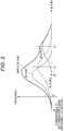
- Fig. 3 illustrates distribution examples of the metric differences (SAMs) for error patterns having different Euclidean distances from one another. Note that in Fig. 3 , the vertical axis represents the frequency of sampling and the horizontal axis represents the value of the metric difference (SAM).
- Fig. 3 for example, three error patterns PTk (k is 1 to 3) mainly contribute to actual error occurrence, and examples of distributions of the metric differences (SAMs) are illustrated.
- the distribution illustrated as SAM1 in Fig. 3 is assumed to be a distribution of the metric difference (SAM) for an error pattern PT1 corresponding to a so-called one-bit error in which a different bit number between the bit sequence of the maximum likelihood path Pa and the bit sequence of the second path Pb is one bit.
- the distribution illustrated as SAM2 can be exemplified as a distribution of the metric difference (SAM) for an error pattern PT2 corresponding to a two-bit error such as the shortest mark shift or the like
- the distribution illustrated as SAM3 can be exemplified as a distribution of the metric difference (SAM) for an error pattern PT3 corresponding to a three-bit error, for example.
- the different bit numbers are different between the maximum likelihood path Pa and the second path Pb, so that in the error patterns PT1 to PT3, the Euclidean distances between the maximum likelihood path Pa and the second path Pb are different.
- an average value of each distribution is the value of the Euclidean distance d k 2 between the maximum likelihood path Pa and the second path Pb in the error pattern PTk. That is, assuming that the distribution of the metric difference (SAM) is a Gaussian distribution as described above, the average value of the distribution should be the value of the metric difference (SAM) when the signal quality is the most favorable.
- the value of the metric difference (SAM) when the best signal quality is obtained in this way is the value of the Euclidean distance between the maximum likelihood path Pa and the second path Pb according to the formula for calculating the metric difference (SAM) according to the above [Expression 1].
- the Euclidean distance between the maximum likelihood path Pa and the second path Pb in the error pattern PT1 is defined as a Euclidean distance d 1 2
- the Euclidean distances between the maximum likelihood path Pa and the second path Pb in the error patterns PT2 and PT3 are a Euclidean distance d 2 2 and a Euclidean distance d 3 2 , respectively.
- a portion where the value of the metric difference (SAM) illustrated on the horizontal axis in Fig. 3 becomes “0" is, as can be understood from the description about the metric difference (SAM), a portion where the value of the path metric for the maximum likelihood path Pa and the value of the path metric for the second path Pb become the same value, and thus a portion where the possibility of detection error is the highest.
- a portion that exceeds (falls below) the portion where the value of the metric difference (SAM) becomes "0" indicates a portion where a detection error actually occurs, and this portion is a portion impossible to observe in PRML. That is, the value of the metric difference (SAM) becoming a negative value, exceeding "0", as described above, means that the value of the path metric for the second path Pb becomes smaller than the value of the path metric for the maximum likelihood path Pa.
- a path with the smallest value of the path metric is detected as the maximum likelihood path. Therefore, it is not possible that the value of the metric difference (SAM) becomes a negative value. Therefore, it is impossible to actually observe the portion where a detection error occurs.
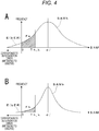
- Fig. 4A illustrates a distribution (SAMk) of the metric difference (SAM) with a certain error pattern PTk.
- the vertical axis represents the sampling frequency and the horizontal axis represents the value of the metric difference (SAM) in Fig. 4A , similarly to Fig. 3 .
- the error rate is assumed to be estimated by setting a predetermined threshold value (Th_k) for the value of the metric difference (SAM), as illustrated in Fig. 4A , and obtaining an appearance frequency (Fk) of the value of the metric difference (SAM) that falls below the predetermined threshold value Th_k.
- Such an appearance frequency Fk of the value of the metric difference (SAM) that falls below the predetermined threshold value Th_k is in a correlation with the portion (bit error rate bER) where the metric difference (SAM) ⁇ 0.
- the distribution SAMk at that time becomes a distribution in which the base relatively expands as illustrated in Fig. 4A , for example.
- the appearance frequency Fk (the area of the portion Fk in Fig. 4A ) also tends to increase. That is, the appearance frequency Fk also rises with the rise of the bit error rate bER.
- the distribution SAMk has a sharper shape, as illustrated in Fig. 4B , for example.
- the appearance frequency Fk also decreases, and therefore it is found that the value of the appearance frequency Fk decreases in response to the decrease in the bit error rate bER.
- an index correlating with the bit error rate bER is obtained by the appearance frequency Fk of the value of the metric difference (SAM) that falls below the threshold value Th_k.
- threshold value Th_k is appropriately respectively set for the distributions (SAM 1, SAM2, and SAM3) of the metric differences (SAM) of the error patterns PT1, PT2, and PT3 for which the evaluation values are calculated, and the appearance frequencies Fk of the values of the metric differences (SAM) falling below the threshold values Th_k are detected and put together, evaluation values highly correlating with nearly an actual bit error rate can be obtained.
- error patterns that are likely to occur are limited to several types, and estimated error rates obtained for respective patters are added, whereby a total error rate is estimated and the signal quality is quantified.
- Figs. 5 and 6 illustrate error patterns of PR (3, 6, 9, 13, 16, 17, 16, 13, 9, 6, 3) as 11ISI that is examined to adopt in the next generation high density disk system.
- Fig. 5 illustrates error patterns with pattern numbers 1 to 32 assigned in ascending order of the squared Euclidean distance, as various error patterns of 24-bit section. For each error pattern, a squared Euclidean distance, a Hamming distance (error bit number), and the error pattern are illustrated. Although only the pattern numbers up to 32 are illustrated here, there are also patterns after a pattern number 33.
- Fig. 6 illustrates the Hamming distance and the squared Euclidean distance of each error pattern in a range of the pattern numbers up to 500.
- the patterns are distributed in a long tail manner, for which a clear threshold value cannot be set in terms of frequency.
- the way of thinking of specifying error patterns and performing processing is stopped, and a technique coping with every error pattern and obtaining a high correlation with an actual error rate is proposed.
- the signal quality evaluation unit 10 of the present embodiment to be described below can calculate the evaluation value d-MLSE serving as an index of reproduction signal quality without specifying the error pattern.
- Fig. 7 illustrates a configuration of the signal quality evaluation unit 10.
- the signal quality evaluation unit 10 includes a distribution calculation unit 21, a merge error estimation unit 22, an average value calculation unit 23, a bit error estimation unit 24, and a conversion unit 25.
- the path selection margin (metric difference (SAM)) and the path selection error bit number are supplied from an internal calculation result of the maximum likelihood decoding unit 9 (Viterbi detector) to the signal quality evaluation unit 10.
- the path selection margin (metric difference (SAM)) as an instantaneous value is sequentially supplied from the maximum likelihood decoding unit 9 to the distribution calculation unit 21.
- the distribution calculation unit 21 obtains a distribution (histogram) of SAM values.
- the SAM value is originally the metric difference between the maximum likelihood path Pa and the second path Pb as described in [Expression 1], and many resources are required to obtain the SAM value. Therefore, the SAM value simplified by temporary determination is obtained.
- Fig. 8 illustrates an example of the maximum likelihood path Pa and the second path Pb that transition in states S00, S01, S10, and S11.
- ⁇ i, j is the path metric at a branch i at time j.
- ⁇ i, j is the state metric at a state i at the time j.
- Bi is a set of branches transitioning to the state i.
- ⁇ j min i ⁇ ki , k ⁇ B i m
- i m arg min i ⁇ i , j : Minimum state (temporary determination)
- the distribution calculation unit 21 in Fig. 7 counts the frequency of each value with respect to the input SAM value (which may be a simple SAM value) and obtains a distribution.
- Fig. 9 illustrates an example of the SAM distribution.
- the horizontal axis represents the SAM value and the vertical axis represents the appearance frequency. Note that the vertical axis is illustrated on a logarithmic scale. ⁇ is the frequency of each SAM value.
- the path selection error bit number as an instantaneous value is sequentially supplied from the maximum likelihood decoding unit 9 to the average value calculation unit 23 in the signal quality evaluation unit 10 in Fig. 7 .
- the average value calculation unit 23 calculates an average value (average error bit number ⁇ ) of the path selection error bit numbers.
- the path selection error bit number is the number of bits that becomes an error when there is a path selection error, that is, the path selection error bit number can be said to be the number of different bits between the bit sequences of the maximum likelihood path Pa and the second path Pb stored in the path memory.
- An average path memory bit different number is assumed to be the average error bit number ⁇ .
- the average error bit number ⁇ per path merge is expressed as below from a bit different number ⁇ j at the time j.
- ⁇ i, j is a path memory bit string (path selection information) at the branch i at the time j.
- N 1 () is a function to obtain the number of bits 1 in binary representation.
- the merge error estimation unit 22 in the signal quality evaluation unit 10 in Fig. 7 performs an operation to obtain an estimated value of a path selection error rate on the basis of the SAM distribution calculated by the distribution calculation unit 21.
- the merge error estimation unit 22 performs an operation to perform estimation by an error function, regarding a region in which the SAM value is close to zero in the SAM distribution as a normal distribution.
- the SAM distribution as illustrated in Fig. 9 is obtained by the distribution calculation unit 21.
- the SAM distribution is superposition of a very large number of error patterns having different distances (averages and variances) and is a non-normal distribution.
- a critical portion (the SAM value is close to zero) can be relatively favorably approximated to the normal distribution. Therefore, a small region with a small SAM value is cut out and fit in the normal distribution. This is the normal distribution curve (N[ ⁇ , ⁇ , ⁇ 2 ]) illustrated by the solid line in Fig. 9 .
- a path merge error rate (the appearance frequency of SAM ⁇ 0) is estimated from the approximated normal distribution. This error rate is estimated to be equal to the actual error rate.
- ⁇ is a ratio of the area defined by the normal distribution curve in a case of normalizing the whole area of the SAM distribution (an integral value of values of ⁇ ) to "1".
- ⁇ is an average value of the normal distribution, and ⁇ is a standard deviation.
- erfc() is a complementary error function.
- the bit error estimation unit 24 in Fig. 7 obtains an estimated bit error rate sbER as a signal quality evaluation value from the arithmetic result of the merge error estimation unit 22 and the arithmetic result of the average value calculation unit 23.
- the evaluation value d-MLSE obtained by converting the estimated bit error rate sbER into jitter is further output as the signal quality evaluation value.
- bit error estimation unit 24 and the conversion unit 25 function as an evaluation value generation unit.
- the above-described estimated path merge error rate spmER is supplied from the merge error estimation unit 22 to the bit error estimation unit 24 and the average error bit number ⁇ is supplied from the average value calculation unit 23 to the bit error estimation unit 24.
- the bit error estimation unit 24 estimates the bit error rate by multiplying the estimated path merge error rate spmER by the average error bit number ⁇ .
- the estimated bit error rate sbER obtained as described above is supplied to the conversion unit 25.
- the conversion unit 25 obtains the evaluation value d-MLSE converted into jitter from the estimated bit error rate sbER as a final signal evaluation value, as follows. d ⁇ MLSE ⁇ 1 2 2 erf c ⁇ 1 2 sbER
- the evaluation value d-MLSE obtained by the operation is supplied to the optical disk controller unit 15 in Fig. 1 .
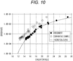
- Fig. 10 illustrates an example of experiment results.
- the experimental results are experimental results in the next generation disk of an 80-GB capacity equivalent to a BD.
- the vertical axis represents the error rate and the horizontal axis represents the evaluation value, and the theoretical curve indicates a relationship between the theoretical error rate and the evaluation value.
- ⁇ represents the value of the evaluation value d-MLSE and the error rate obtained by the method of the embodiment.
- ⁇ represents the evaluation value and the error rate in a case of the method of obtaining the evaluation value, using some specified error patterns (six types), as described above, as a comparative example.
- the estimated error rate is underestimated. That is, a measured error rate becomes higher than the evaluation value. Furthermore, the correlation deteriorates because the whole is estimated from some behavior. In other words, the variation becomes large.
- the signal quality evaluation unit 10 of the embodiment can obtain the evaluation value d-MLSE with high accuracy by a relatively simple operation.
- FIG. 7 illustrates a portion performed by hardware (H/W) and a portion performed by software (S/W) in the configuration of the signal quality evaluation unit 10.
- An operation of the path selection margin (SAM) and measurement of the distribution (histogram), and an operation of the path selection error bit number and an operation of the average value inside the maximum likelihood decoding unit 9 (Viterbi detector) require rates equivalent to a channel clock, respectively. Therefore, implementation by hardware is desirable to realize real-time processing.
- the entire signal quality evaluation unit 10 can be implemented by hardware or by software.
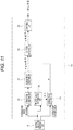
- Fig. 11 illustrates another configuration example of the signal quality evaluation unit 10. Note that the same parts as those in Fig. 7 are denoted by the same reference numerals, and description thereof is omitted.
- a threshold value determination unit 26 is included in addition to the configuration in Fig. 7 .
- the threshold value determination unit 26 inputs the path selection margin (SAM) and confirms whether or not the SAM value is equal or less than a predetermined threshold value th. Then, in a case where the SAM value is not equal to or less than the threshold value th, the threshold value determination unit 26 outputs an enable signal en to the average value calculation unit 23.
- SAM path selection margin
- the average value calculation unit 23 excludes the path selection error bit number at the timing when the enable signal en is supplied from samples for obtaining the average value.
- Fig. 9 illustrates an example of the threshold value th.
- the threshold value th may be a fixed value or a variable value.
- the value when the detection margin can be considered to be small with a value or less, the value may be set as the threshold value th.
- a deterministic value such as a minimum Euclidean distance obtained from an equalization PR class may be used.
- an adaptive value obtained while seeing the distribution of the path selection margin may be used. For example, a mode of the distribution, or the like may be used.
- the path selection margin (SAM) and the path selection error bit number are instantaneous values obtained for each sample.
- the path selection margin can be regarded as a sample close to a detection error or a sample that has caused a detection error.
- path selection error bit number As for the path selection error bit number, it is conceivable that a result closer to a behavior at the time of actual detection error can be obtained by obtaining an average value for samples close to a detection error.
- the threshold value th is set, and an average path selection error number is obtained for samples equal to or less than the threshold value th with respect to the SAM value.
- the reliability of the measurement result can be enhanced by selecting the samples in this manner. As a result, improvement of the accuracy of the final evaluation value d-MLSE can also be expected.
- Fig. 12 illustrates a configuration of the maximum likelihood decoding unit 9 in a case of using an adaptive Viterbi detector.
- the signal quality evaluation unit 10 of the present embodiment is suitable even in the case where the maximum likelihood decoding unit 9 is the adaptive Viterbi detector.
- An adaptive Viterbi detector is disclosed in Japanese Patent No. 4622632 , for example.
- the maximum likelihood decoding unit 9 in Fig. 12 includes a branch metric calculation unit (BMC) 32 that calculates a branch metric for each branch from the reproduction signal RF (EQ) from the PR equalization unit 8, a path metric updating unit (ACS) 33 that takes in the branch metrics, compares the branches, selects a path, and updates the path metric, and a path memory update unit (PMEM) 34 that updates the path memory according to the selected path information.
- BMC branch metric calculation unit
- ACS path metric updating unit
- PMEM path memory update unit
- an adaptive reference level generation circuit 35 for generating a reference level according to the level of the reproduction signal RF (EQ) is provided to realize an adaptive Viterbi detection operation.
- the branch metric calculation unit 32 calculates the branch metric corresponding to each branch on the basis of the value of the reproduction signal RF (EQ) from the PR equalization unit 8 and a value (reference level data) of each reference level set by the adaptive reference level generation circuit 35.
- the adaptive reference level generation circuit 35 generates the reference level data to be set to the branch metric calculation unit 32 on the basis of the reproduction signal RF (EQ) and the binarized data DD from the path memory update unit 34.
- the adaptive reference level generation circuit 35 in this case is provided with x low pass filters provided according to the number x of reference levels set corresponding to the PR class to be adopted. Then, the value of the reproduction signal RF (EQ) is distributed and input to the low pass filters in accordance with the pattern of the binarized data DD, and the value of the reproduction signal RF is averaged for each reference level. The result is output as the reference level data.
- the reference level data adapted to the actual reproduction signal RF can be obtained in this way, whereby an appropriate value can be obtained as the branch metric calculated by the branch metric calculation unit 32 even in a case where an ideal reproduction signal RF (EQ) expected in the PR class cannot be obtained, and the reliability of the binarized data DD can be improved.
- the signal quality evaluation unit 10 of the embodiment is used in combination with such an adaptive Viterbi detector, the internal reference level of the Viterbi detector changes according to an input signal, and as a result, the Euclidean distance at the time of detection changes.
- the change of the adaptive Viterbi is already incorporated at the time of the operation of the path selection margin (SAM) defined as the difference in metrics, and normalization with the Euclidean distance is not required in the subsequent operation. For this reason, combination with the adaptive Viterbi is possible without introducing a special operation, and an evaluation value with high accuracy can be generated with a simpler configuration.
- SAM path selection margin
- the signal quality evaluation unit 10 of the embodiment includes the merge error estimation unit 22 (first arithmetic unit) that obtains the estimated value (estimated path merge error rate spmER) of the path selection error rate on the basis of the distribution of the path metric difference between the maximum likelihood path Pa of each time, the maximum likelihood path being the detection path in the maximum likelihood decoding, and the second path Pb having the second highest likelihood in the PRML decoding system to perform partial response equalization and the maximum likelihood decoding for the reproduction signal of the bit information.
- the merge error estimation unit 22 first arithmetic unit
- the signal quality evaluation unit 10 includes the average value calculation unit 23 (second arithmetic unit) that obtains the average error bit number in erroneous detection from the bit difference number (path selection error bit number) between the maximum likelihood path Pa and the second path Pb at the time of path selection of each time in the maximum likelihood decoding. Furthermore, the signal quality evaluation unit 10 includes the evaluation value generation unit (the bit error estimation unit 24 and the conversion unit 25) that obtains the estimated bit error rate sbER from the estimated path merge error rate spmER as the arithmetic result by the merge error estimation unit 22 and the average error bit number ⁇ as the arithmetic result by the average value calculation unit 23, and generates the evaluation value d-MLSE according to the estimated bit error rate sbER.
- the evaluation value generation unit the bit error estimation unit 24 and the conversion unit 25
- the evaluation value is not calculated for some error patterns specified in advance, and the evaluation value covering all error patterns that are likely to occur is obtained. Signal evaluation with higher accuracy (having a high correlation with the actual error rate) becomes thus possible by simple operations. Since the error patterns are not particularly limited, the configuration is very effective for a reproduction system having various error patterns that are likely to occur.
- the configuration does not specify an error pattern, a pattern filter for determining an error pattern is unnecessary. Then, as measurement on processing, only the frequency counter of the distribution calculation unit 21 is required. Therefore, the configuration is not complicated. Especially, the circuit scale does not become larger as the constraint length becomes longer.
- the configuration can cope with any PR class.
- the merge error estimation unit 22 (first arithmetic unit) obtains the estimated value (estimated path merge error rate spmER) of the path selection error rate from the normal distribution approximated to the distribution of the path metric difference (see Fig. 9 ).
- the distribution of the path metric difference is superposition of a very large number of error patterns having different distances and is non-normal distribution. However, a portion close to zero can be relatively favorably approximated to the normal distribution.
- the path merge error rate (that is, the appearance frequency at which the path metric difference becomes less than 0) is estimated from this approximated normal distribution. As a result, the path merge error rate with high accuracy can be obtained by the simple operation technique.
- the average value calculation unit 23 (second arithmetic unit) obtains the average error bit number, using the bit difference number between the maximum likelihood path and the second path of the case where the value of the path metric difference between the maximum likelihood path and the second path becomes equal to or less than a predetermined threshold value.
- the path metric difference (path selection margin: SAM value) and the bit difference number (path selection error bit number) are instantaneous values obtained for each sample.
- the path selection margin value SAM value
- the path selection margin value can be regarded as a sample close to a detection error or a sample that has caused a detection error.
- the path selection error bit number it is conceivable that a result closer to a behavior at the time of actual detection error can be obtained by obtaining an average value for samples close to a detection error. Therefore, an average path selection error number is obtained for samples equal to or less than a certain threshold value th with respect to the SAM value. As a result, the accuracy of the average error bit number is improved and improvement of the accuracy of the final evaluation value can also be expected.
- the signal quality evaluation unit 10 of the embodiment generates and outputs the evaluation value d-MLSE obtained by converting the estimated bit error rate sbER into jitter.
- the estimated bit error rate sbER also has a property as the evaluation value. Therefore, the estimated bit error rate sbER may be output as the evaluation value in place of the evaluation value d-MLSE or together with the evaluation value d-MLSE.
- the reproduction device 1 (see Fig. 1 ) of the embodiment includes a reproduction unit (2, 3, 4, 5, 6) that reproduces the reproduction signal of the bit information from the optical disk 90 (recording medium) and a decoding unit (the PR equalization unit 8 and the maximum likelihood decoding unit 9) that performs the PRML decoding processing by partial response equalization and maximum likelihood decoding for the reproduction signal to decode the binarized data DD. Then, the reproduction device 1 includes the signal quality evaluation unit 10 including the merge error estimation unit 22 (first arithmetic unit), the average value calculation unit 23 (second arithmetic unit), and the bit error estimation unit 24 and the conversion unit 25 (evaluation value generation unit).
- the adaptive Viterbi detector in which the reference level used for calculation of the branch metric is set to be variable according to the level of the reproduction signal may be used.
- the change of the adaptive Viterbi is already incorporated at the time of the operation of the path selection margin (SAM) defined as the metric difference, and normalization with the Euclidean distance is not required in the subsequent operation. Therefore, combination with the adaptive Viterbi without introducing special operations is possible. Therefore, an evaluation value with high accuracy can be obtained with a simpler configuration even in a case of using the adaptive Viterbi detector.
- SAM path selection margin
- PR 3, 6, 9, 13, 16, 17, 16, 13, 9, 6, 3
- PR 3, 6, 9, 13, 16, 17, 16, 13, 9, 6, 3
- various PR classes and ISI can be adopted in the reproduction device 1 of the embodiment.
- the technology of the present disclosure can be widely applied to decoding of bit information reproduced from a recording medium and decoding of transmitted bit information.
- the recording medium is not limited to an optical disk and any recording medium is assumed.
Landscapes
- Engineering & Computer Science (AREA)
- Signal Processing (AREA)
- Physics & Mathematics (AREA)
- Probability & Statistics with Applications (AREA)
- Theoretical Computer Science (AREA)
- Signal Processing For Digital Recording And Reproducing (AREA)
- Error Detection And Correction (AREA)
Applications Claiming Priority (2)
| Application Number | Priority Date | Filing Date | Title |
|---|---|---|---|
| JP2016168028 | 2016-08-30 | ||
| PCT/JP2017/021684 WO2018042814A1 (ja) | 2016-08-30 | 2017-06-12 | 信号品質評価装置、信号品質評価値生成方法、再生装置 |
Publications (3)
| Publication Number | Publication Date |
|---|---|
| EP3486907A1 true EP3486907A1 (de) | 2019-05-22 |
| EP3486907A4 EP3486907A4 (de) | 2019-08-21 |
| EP3486907B1 EP3486907B1 (de) | 2022-05-11 |
Family
ID=61300512
Family Applications (1)
| Application Number | Title | Priority Date | Filing Date |
|---|---|---|---|
| EP17845825.3A Not-in-force EP3486907B1 (de) | 2016-08-30 | 2017-06-12 | Vorrichtung zur bewertung der signalqualität, verfahren zur erzeugung des signalqualitätsbewertungswerts und wiedergabevorrichtung |
Country Status (6)
| Country | Link |
|---|---|
| US (1) | US10490222B2 (de) |
| EP (1) | EP3486907B1 (de) |
| JP (1) | JP6918429B2 (de) |
| CN (1) | CN109643559B (de) |
| TW (1) | TWI638539B (de) |
| WO (1) | WO2018042814A1 (de) |
Families Citing this family (1)
| Publication number | Priority date | Publication date | Assignee | Title |
|---|---|---|---|---|
| WO2021153260A1 (ja) * | 2020-01-30 | 2021-08-05 | ソニーグループ株式会社 | 信号処理装置、信号処理方法、及び、プログラム |
Family Cites Families (15)
| Publication number | Priority date | Publication date | Assignee | Title |
|---|---|---|---|---|
| US6678230B2 (en) * | 2000-10-31 | 2004-01-13 | Matsushita Electric Industrial Co., Ltd. | Waveform equalizer for a reproduction signal obtained by reproducing marks and non-marks recorded on a recording medium |
| US6789225B2 (en) * | 2001-07-12 | 2004-09-07 | Sony Corporation | Bit error position estimation in data decoder |
| US20030067998A1 (en) * | 2001-07-19 | 2003-04-10 | Matsushita Electric Industrial Co., Ltd. | Method for evaluating the quality of read signal and apparatus for reading information |
| JP2004071069A (ja) * | 2002-08-07 | 2004-03-04 | Nippon Hoso Kyokai <Nhk> | 光ディスクのビット誤り率推定装置、およびビット誤り率を推定するためのコンピュータプログラム |
| JP4143489B2 (ja) * | 2003-07-09 | 2008-09-03 | キヤノン株式会社 | 情報再生装置 |
| JP4142537B2 (ja) * | 2003-09-19 | 2008-09-03 | 松下電器産業株式会社 | 光ディスク装置 |
| JP4622632B2 (ja) * | 2005-03-31 | 2011-02-02 | ソニー株式会社 | 最尤復号装置、信号評価方法、再生装置 |
| JP4750488B2 (ja) * | 2005-07-08 | 2011-08-17 | ソニー株式会社 | 評価装置、再生装置、評価方法 |
| JP5003284B2 (ja) * | 2007-05-24 | 2012-08-15 | 日本電気株式会社 | 信号品質測定装置及び情報再生装置 |
| JP4885799B2 (ja) * | 2007-06-05 | 2012-02-29 | シャープ株式会社 | 信号評価装置、信号評価方法、信号評価プログラム、およびコンピュータ読み取り可能な記録媒体 |
| JP5050805B2 (ja) * | 2007-11-22 | 2012-10-17 | 日本電気株式会社 | 信号品質測定装置、方法、及び、情報記録再生装置 |
| KR20100115699A (ko) * | 2008-02-28 | 2010-10-28 | 파나소닉 주식회사 | 신호 평가 방법 및 신호 평가 장치 |
| JP4959749B2 (ja) * | 2009-05-08 | 2012-06-27 | 株式会社日立製作所 | 記録条件の調整方法及び光ディスク装置 |
| TWI530942B (zh) * | 2012-06-04 | 2016-04-21 | Sony Corp | A signal quality evaluation apparatus, a signal quality evaluation method, and a reproduction apparatus |
| JP2015035240A (ja) * | 2013-08-08 | 2015-02-19 | 日立コンシューマエレクトロニクス株式会社 | チャネルビットワード処理器、prml復号器、光情報記録再生装置 |
-
2017
- 2017-06-12 CN CN201780050887.7A patent/CN109643559B/zh active Active
- 2017-06-12 US US16/324,206 patent/US10490222B2/en active Active
- 2017-06-12 WO PCT/JP2017/021684 patent/WO2018042814A1/ja not_active Ceased
- 2017-06-12 EP EP17845825.3A patent/EP3486907B1/de not_active Not-in-force
- 2017-06-12 JP JP2018536961A patent/JP6918429B2/ja active Active
- 2017-07-27 TW TW106125326A patent/TWI638539B/zh active
Also Published As
| Publication number | Publication date |
|---|---|
| CN109643559B (zh) | 2020-11-27 |
| JP6918429B2 (ja) | 2021-08-11 |
| US20190172489A1 (en) | 2019-06-06 |
| EP3486907A4 (de) | 2019-08-21 |
| EP3486907B1 (de) | 2022-05-11 |
| WO2018042814A1 (ja) | 2018-03-08 |
| TW201810979A (zh) | 2018-03-16 |
| CN109643559A (zh) | 2019-04-16 |
| JPWO2018042814A1 (ja) | 2019-06-24 |
| US10490222B2 (en) | 2019-11-26 |
| TWI638539B (zh) | 2018-10-11 |
Similar Documents
| Publication | Publication Date | Title |
|---|---|---|
| US20100014405A1 (en) | Method for Evaluating Quality of Read Signal And Apparatus for Reading Information | |
| JP4622632B2 (ja) | 最尤復号装置、信号評価方法、再生装置 | |
| JP4750488B2 (ja) | 評価装置、再生装置、評価方法 | |
| JP3857685B2 (ja) | 信号評価方法と情報記録再生装置と情報再生装置及び情報媒体 | |
| JP5441906B2 (ja) | 再生信号評価方法、再生信号評価装置及びこれを備えた光ディスク装置 | |
| EP3486907B1 (de) | Vorrichtung zur bewertung der signalqualität, verfahren zur erzeugung des signalqualitätsbewertungswerts und wiedergabevorrichtung | |
| JP3711140B2 (ja) | 情報記録再生装置及びその信号評価方法 | |
| EP2858070B1 (de) | Vorrichtung zur signalqualitätsbeurteilung, verfahren zur signalqualitätsbeurteilung und wiedergabevorrichtung | |
| JP2005166221A (ja) | 情報再生方法及び情報再生装置 | |
| JP2005332437A (ja) | 再生信号評価方法及び情報記録再生装置 | |
| EP2409448B1 (de) | Signalqualitätsmessvorrichtung und verfahren dafür | |
| JP3756927B2 (ja) | 情報記録再生装置及びその信号評価方法 | |
| US20050058191A1 (en) | Method and apparatus for detecting signal quality and recording medium storing program therefor | |
| JPWO2009122642A1 (ja) | 再生信号品質評価装置及び方法 |
Legal Events
| Date | Code | Title | Description |
|---|---|---|---|
| STAA | Information on the status of an ep patent application or granted ep patent |
Free format text: STATUS: THE INTERNATIONAL PUBLICATION HAS BEEN MADE |
|
| PUAI | Public reference made under article 153(3) epc to a published international application that has entered the european phase |
Free format text: ORIGINAL CODE: 0009012 |
|
| STAA | Information on the status of an ep patent application or granted ep patent |
Free format text: STATUS: REQUEST FOR EXAMINATION WAS MADE |
|
| 17P | Request for examination filed |
Effective date: 20190214 |
|
| AK | Designated contracting states |
Kind code of ref document: A1 Designated state(s): AL AT BE BG CH CY CZ DE DK EE ES FI FR GB GR HR HU IE IS IT LI LT LU LV MC MK MT NL NO PL PT RO RS SE SI SK SM TR |
|
| AX | Request for extension of the european patent |
Extension state: BA ME |
|
| REG | Reference to a national code |
Ref country code: DE Ref legal event code: R079 Ref document number: 602017057442 Country of ref document: DE Free format text: PREVIOUS MAIN CLASS: G11B0020180000 Ipc: G11B0020100000 |
|
| A4 | Supplementary search report drawn up and despatched |
Effective date: 20190719 |
|
| RIC1 | Information provided on ipc code assigned before grant |
Ipc: G11B 20/10 20060101AFI20190715BHEP |
|
| DAV | Request for validation of the european patent (deleted) | ||
| DAX | Request for extension of the european patent (deleted) | ||
| STAA | Information on the status of an ep patent application or granted ep patent |
Free format text: STATUS: EXAMINATION IS IN PROGRESS |
|
| 17Q | First examination report despatched |
Effective date: 20200217 |
|
| GRAP | Despatch of communication of intention to grant a patent |
Free format text: ORIGINAL CODE: EPIDOSNIGR1 |
|
| STAA | Information on the status of an ep patent application or granted ep patent |
Free format text: STATUS: GRANT OF PATENT IS INTENDED |
|
| INTG | Intention to grant announced |
Effective date: 20211213 |
|
| GRAS | Grant fee paid |
Free format text: ORIGINAL CODE: EPIDOSNIGR3 |
|
| GRAA | (expected) grant |
Free format text: ORIGINAL CODE: 0009210 |
|
| STAA | Information on the status of an ep patent application or granted ep patent |
Free format text: STATUS: THE PATENT HAS BEEN GRANTED |
|
| AK | Designated contracting states |
Kind code of ref document: B1 Designated state(s): AL AT BE BG CH CY CZ DE DK EE ES FI FR GB GR HR HU IE IS IT LI LT LU LV MC MK MT NL NO PL PT RO RS SE SI SK SM TR |
|
| REG | Reference to a national code |
Ref country code: GB Ref legal event code: FG4D |
|
| REG | Reference to a national code |
Ref country code: CH Ref legal event code: EP |
|
| REG | Reference to a national code |
Ref country code: AT Ref legal event code: REF Ref document number: 1492145 Country of ref document: AT Kind code of ref document: T Effective date: 20220515 |
|
| REG | Reference to a national code |
Ref country code: NL Ref legal event code: FP |
|
| REG | Reference to a national code |
Ref country code: DE Ref legal event code: R096 Ref document number: 602017057442 Country of ref document: DE |
|
| REG | Reference to a national code |
Ref country code: IE Ref legal event code: FG4D |
|
| PGFP | Annual fee paid to national office [announced via postgrant information from national office to epo] |
Ref country code: NL Payment date: 20220621 Year of fee payment: 6 Ref country code: DE Payment date: 20220531 Year of fee payment: 6 |
|
| REG | Reference to a national code |
Ref country code: LT Ref legal event code: MG9D |
|
| REG | Reference to a national code |
Ref country code: AT Ref legal event code: MK05 Ref document number: 1492145 Country of ref document: AT Kind code of ref document: T Effective date: 20220511 |
|
| PG25 | Lapsed in a contracting state [announced via postgrant information from national office to epo] |
Ref country code: SE Free format text: LAPSE BECAUSE OF FAILURE TO SUBMIT A TRANSLATION OF THE DESCRIPTION OR TO PAY THE FEE WITHIN THE PRESCRIBED TIME-LIMIT Effective date: 20220511 Ref country code: PT Free format text: LAPSE BECAUSE OF FAILURE TO SUBMIT A TRANSLATION OF THE DESCRIPTION OR TO PAY THE FEE WITHIN THE PRESCRIBED TIME-LIMIT Effective date: 20220912 Ref country code: NO Free format text: LAPSE BECAUSE OF FAILURE TO SUBMIT A TRANSLATION OF THE DESCRIPTION OR TO PAY THE FEE WITHIN THE PRESCRIBED TIME-LIMIT Effective date: 20220811 Ref country code: LT Free format text: LAPSE BECAUSE OF FAILURE TO SUBMIT A TRANSLATION OF THE DESCRIPTION OR TO PAY THE FEE WITHIN THE PRESCRIBED TIME-LIMIT Effective date: 20220511 Ref country code: HR Free format text: LAPSE BECAUSE OF FAILURE TO SUBMIT A TRANSLATION OF THE DESCRIPTION OR TO PAY THE FEE WITHIN THE PRESCRIBED TIME-LIMIT Effective date: 20220511 Ref country code: GR Free format text: LAPSE BECAUSE OF FAILURE TO SUBMIT A TRANSLATION OF THE DESCRIPTION OR TO PAY THE FEE WITHIN THE PRESCRIBED TIME-LIMIT Effective date: 20220812 Ref country code: FI Free format text: LAPSE BECAUSE OF FAILURE TO SUBMIT A TRANSLATION OF THE DESCRIPTION OR TO PAY THE FEE WITHIN THE PRESCRIBED TIME-LIMIT Effective date: 20220511 Ref country code: ES Free format text: LAPSE BECAUSE OF FAILURE TO SUBMIT A TRANSLATION OF THE DESCRIPTION OR TO PAY THE FEE WITHIN THE PRESCRIBED TIME-LIMIT Effective date: 20220511 Ref country code: BG Free format text: LAPSE BECAUSE OF FAILURE TO SUBMIT A TRANSLATION OF THE DESCRIPTION OR TO PAY THE FEE WITHIN THE PRESCRIBED TIME-LIMIT Effective date: 20220811 Ref country code: AT Free format text: LAPSE BECAUSE OF FAILURE TO SUBMIT A TRANSLATION OF THE DESCRIPTION OR TO PAY THE FEE WITHIN THE PRESCRIBED TIME-LIMIT Effective date: 20220511 |
|
| PG25 | Lapsed in a contracting state [announced via postgrant information from national office to epo] |
Ref country code: RS Free format text: LAPSE BECAUSE OF FAILURE TO SUBMIT A TRANSLATION OF THE DESCRIPTION OR TO PAY THE FEE WITHIN THE PRESCRIBED TIME-LIMIT Effective date: 20220511 Ref country code: PL Free format text: LAPSE BECAUSE OF FAILURE TO SUBMIT A TRANSLATION OF THE DESCRIPTION OR TO PAY THE FEE WITHIN THE PRESCRIBED TIME-LIMIT Effective date: 20220511 Ref country code: LV Free format text: LAPSE BECAUSE OF FAILURE TO SUBMIT A TRANSLATION OF THE DESCRIPTION OR TO PAY THE FEE WITHIN THE PRESCRIBED TIME-LIMIT Effective date: 20220511 Ref country code: IS Free format text: LAPSE BECAUSE OF FAILURE TO SUBMIT A TRANSLATION OF THE DESCRIPTION OR TO PAY THE FEE WITHIN THE PRESCRIBED TIME-LIMIT Effective date: 20220911 |
|
| PG25 | Lapsed in a contracting state [announced via postgrant information from national office to epo] |
Ref country code: SM Free format text: LAPSE BECAUSE OF FAILURE TO SUBMIT A TRANSLATION OF THE DESCRIPTION OR TO PAY THE FEE WITHIN THE PRESCRIBED TIME-LIMIT Effective date: 20220511 Ref country code: SK Free format text: LAPSE BECAUSE OF FAILURE TO SUBMIT A TRANSLATION OF THE DESCRIPTION OR TO PAY THE FEE WITHIN THE PRESCRIBED TIME-LIMIT Effective date: 20220511 Ref country code: RO Free format text: LAPSE BECAUSE OF FAILURE TO SUBMIT A TRANSLATION OF THE DESCRIPTION OR TO PAY THE FEE WITHIN THE PRESCRIBED TIME-LIMIT Effective date: 20220511 Ref country code: EE Free format text: LAPSE BECAUSE OF FAILURE TO SUBMIT A TRANSLATION OF THE DESCRIPTION OR TO PAY THE FEE WITHIN THE PRESCRIBED TIME-LIMIT Effective date: 20220511 Ref country code: DK Free format text: LAPSE BECAUSE OF FAILURE TO SUBMIT A TRANSLATION OF THE DESCRIPTION OR TO PAY THE FEE WITHIN THE PRESCRIBED TIME-LIMIT Effective date: 20220511 Ref country code: CZ Free format text: LAPSE BECAUSE OF FAILURE TO SUBMIT A TRANSLATION OF THE DESCRIPTION OR TO PAY THE FEE WITHIN THE PRESCRIBED TIME-LIMIT Effective date: 20220511 |
|
| REG | Reference to a national code |
Ref country code: CH Ref legal event code: PL |
|
| REG | Reference to a national code |
Ref country code: DE Ref legal event code: R097 Ref document number: 602017057442 Country of ref document: DE |
|
| REG | Reference to a national code |
Ref country code: BE Ref legal event code: MM Effective date: 20220630 |
|
| PG25 | Lapsed in a contracting state [announced via postgrant information from national office to epo] |
Ref country code: MC Free format text: LAPSE BECAUSE OF FAILURE TO SUBMIT A TRANSLATION OF THE DESCRIPTION OR TO PAY THE FEE WITHIN THE PRESCRIBED TIME-LIMIT Effective date: 20220511 |
|
| PLBE | No opposition filed within time limit |
Free format text: ORIGINAL CODE: 0009261 |
|
| STAA | Information on the status of an ep patent application or granted ep patent |
Free format text: STATUS: NO OPPOSITION FILED WITHIN TIME LIMIT |
|
| PG25 | Lapsed in a contracting state [announced via postgrant information from national office to epo] |
Ref country code: AL Free format text: LAPSE BECAUSE OF FAILURE TO SUBMIT A TRANSLATION OF THE DESCRIPTION OR TO PAY THE FEE WITHIN THE PRESCRIBED TIME-LIMIT Effective date: 20220511 |
|
| 26N | No opposition filed |
Effective date: 20230214 |
|
| GBPC | Gb: european patent ceased through non-payment of renewal fee |
Effective date: 20220811 |
|
| PG25 | Lapsed in a contracting state [announced via postgrant information from national office to epo] |
Ref country code: LU Free format text: LAPSE BECAUSE OF NON-PAYMENT OF DUE FEES Effective date: 20220612 Ref country code: LI Free format text: LAPSE BECAUSE OF NON-PAYMENT OF DUE FEES Effective date: 20220630 Ref country code: IE Free format text: LAPSE BECAUSE OF NON-PAYMENT OF DUE FEES Effective date: 20220612 Ref country code: FR Free format text: LAPSE BECAUSE OF NON-PAYMENT OF DUE FEES Effective date: 20220711 Ref country code: CH Free format text: LAPSE BECAUSE OF NON-PAYMENT OF DUE FEES Effective date: 20220630 |
|
| PG25 | Lapsed in a contracting state [announced via postgrant information from national office to epo] |
Ref country code: SI Free format text: LAPSE BECAUSE OF FAILURE TO SUBMIT A TRANSLATION OF THE DESCRIPTION OR TO PAY THE FEE WITHIN THE PRESCRIBED TIME-LIMIT Effective date: 20220511 Ref country code: BE Free format text: LAPSE BECAUSE OF NON-PAYMENT OF DUE FEES Effective date: 20220630 |
|
| P01 | Opt-out of the competence of the unified patent court (upc) registered |
Effective date: 20230528 |
|
| PG25 | Lapsed in a contracting state [announced via postgrant information from national office to epo] |
Ref country code: GB Free format text: LAPSE BECAUSE OF NON-PAYMENT OF DUE FEES Effective date: 20220811 |
|
| REG | Reference to a national code |
Ref country code: DE Ref legal event code: R119 Ref document number: 602017057442 Country of ref document: DE |
|
| PG25 | Lapsed in a contracting state [announced via postgrant information from national office to epo] |
Ref country code: IT Free format text: LAPSE BECAUSE OF FAILURE TO SUBMIT A TRANSLATION OF THE DESCRIPTION OR TO PAY THE FEE WITHIN THE PRESCRIBED TIME-LIMIT Effective date: 20220511 |
|
| REG | Reference to a national code |
Ref country code: NL Ref legal event code: MM Effective date: 20230701 |
|
| PG25 | Lapsed in a contracting state [announced via postgrant information from national office to epo] |
Ref country code: NL Free format text: LAPSE BECAUSE OF NON-PAYMENT OF DUE FEES Effective date: 20230701 Ref country code: HU Free format text: LAPSE BECAUSE OF FAILURE TO SUBMIT A TRANSLATION OF THE DESCRIPTION OR TO PAY THE FEE WITHIN THE PRESCRIBED TIME-LIMIT; INVALID AB INITIO Effective date: 20170612 |
|
| PG25 | Lapsed in a contracting state [announced via postgrant information from national office to epo] |
Ref country code: MK Free format text: LAPSE BECAUSE OF FAILURE TO SUBMIT A TRANSLATION OF THE DESCRIPTION OR TO PAY THE FEE WITHIN THE PRESCRIBED TIME-LIMIT Effective date: 20220511 Ref country code: DE Free format text: LAPSE BECAUSE OF NON-PAYMENT OF DUE FEES Effective date: 20240103 Ref country code: CY Free format text: LAPSE BECAUSE OF FAILURE TO SUBMIT A TRANSLATION OF THE DESCRIPTION OR TO PAY THE FEE WITHIN THE PRESCRIBED TIME-LIMIT Effective date: 20220511 |
|
| PG25 | Lapsed in a contracting state [announced via postgrant information from national office to epo] |
Ref country code: TR Free format text: LAPSE BECAUSE OF FAILURE TO SUBMIT A TRANSLATION OF THE DESCRIPTION OR TO PAY THE FEE WITHIN THE PRESCRIBED TIME-LIMIT Effective date: 20220511 |
|
| PG25 | Lapsed in a contracting state [announced via postgrant information from national office to epo] |
Ref country code: MT Free format text: LAPSE BECAUSE OF FAILURE TO SUBMIT A TRANSLATION OF THE DESCRIPTION OR TO PAY THE FEE WITHIN THE PRESCRIBED TIME-LIMIT Effective date: 20220511 |
|
| PG25 | Lapsed in a contracting state [announced via postgrant information from national office to epo] |
Ref country code: BG Free format text: LAPSE BECAUSE OF FAILURE TO SUBMIT A TRANSLATION OF THE DESCRIPTION OR TO PAY THE FEE WITHIN THE PRESCRIBED TIME-LIMIT Effective date: 20220511 |
|
| PG25 | Lapsed in a contracting state [announced via postgrant information from national office to epo] |
Ref country code: BG Free format text: LAPSE BECAUSE OF FAILURE TO SUBMIT A TRANSLATION OF THE DESCRIPTION OR TO PAY THE FEE WITHIN THE PRESCRIBED TIME-LIMIT Effective date: 20220511 |