EP3486735A1 - Second reset clock mechanism with snail cam - Google Patents
Second reset clock mechanism with snail cam Download PDFInfo
- Publication number
- EP3486735A1 EP3486735A1 EP17202604.9A EP17202604A EP3486735A1 EP 3486735 A1 EP3486735 A1 EP 3486735A1 EP 17202604 A EP17202604 A EP 17202604A EP 3486735 A1 EP3486735 A1 EP 3486735A1
- Authority
- EP
- European Patent Office
- Prior art keywords
- hammer
- cam
- seconds
- shaft
- hand
- Prior art date
- Legal status (The legal status is an assumption and is not a legal conclusion. Google has not performed a legal analysis and makes no representation as to the accuracy of the status listed.)
- Granted
Links
- 230000007246 mechanism Effects 0.000 title claims abstract description 49
- 241000237858 Gastropoda Species 0.000 title 1
- 230000002093 peripheral effect Effects 0.000 claims description 4
- 230000000694 effects Effects 0.000 description 4
- 230000008901 benefit Effects 0.000 description 3
- 238000004804 winding Methods 0.000 description 3
- 241000920340 Pion Species 0.000 description 2
- 229910000831 Steel Inorganic materials 0.000 description 2
- 239000011324 bead Substances 0.000 description 2
- 230000005540 biological transmission Effects 0.000 description 2
- 230000001627 detrimental effect Effects 0.000 description 2
- 210000004247 hand Anatomy 0.000 description 2
- 230000009191 jumping Effects 0.000 description 2
- 238000004519 manufacturing process Methods 0.000 description 2
- 239000000463 material Substances 0.000 description 2
- 229910052751 metal Inorganic materials 0.000 description 2
- 239000002184 metal Substances 0.000 description 2
- 229920001343 polytetrafluoroethylene Polymers 0.000 description 2
- 239000004810 polytetrafluoroethylene Substances 0.000 description 2
- 235000020004 porter Nutrition 0.000 description 2
- 239000010959 steel Substances 0.000 description 2
- OKTJSMMVPCPJKN-UHFFFAOYSA-N Carbon Chemical compound [C] OKTJSMMVPCPJKN-UHFFFAOYSA-N 0.000 description 1
- 241000238366 Cephalopoda Species 0.000 description 1
- 241001415961 Gaviidae Species 0.000 description 1
- 241001481166 Nautilus Species 0.000 description 1
- 229920006362 Teflon® Polymers 0.000 description 1
- 229910052799 carbon Inorganic materials 0.000 description 1
- 210000000078 claw Anatomy 0.000 description 1
- 239000002131 composite material Substances 0.000 description 1
- 125000004122 cyclic group Chemical group 0.000 description 1
- 238000006073 displacement reaction Methods 0.000 description 1
- 239000000835 fiber Substances 0.000 description 1
- 239000010437 gem Substances 0.000 description 1
- 229910001751 gemstone Inorganic materials 0.000 description 1
- 230000007774 longterm Effects 0.000 description 1
- 239000011159 matrix material Substances 0.000 description 1
- 230000010355 oscillation Effects 0.000 description 1
- 230000008447 perception Effects 0.000 description 1
- 239000004033 plastic Substances 0.000 description 1
- BASFCYQUMIYNBI-UHFFFAOYSA-N platinum Chemical group [Pt] BASFCYQUMIYNBI-UHFFFAOYSA-N 0.000 description 1
- 229920000642 polymer Polymers 0.000 description 1
- -1 polytetrafluoroethylene Polymers 0.000 description 1
- 239000010453 quartz Substances 0.000 description 1
- 230000000284 resting effect Effects 0.000 description 1
- 239000010979 ruby Substances 0.000 description 1
- 229910001750 ruby Inorganic materials 0.000 description 1
- VYPSYNLAJGMNEJ-UHFFFAOYSA-N silicon dioxide Inorganic materials O=[Si]=O VYPSYNLAJGMNEJ-UHFFFAOYSA-N 0.000 description 1
- 229920002994 synthetic fiber Polymers 0.000 description 1
- 210000000707 wrist Anatomy 0.000 description 1
Images


Classifications
-
- G—PHYSICS
- G04—HOROLOGY
- G04F—TIME-INTERVAL MEASURING
- G04F7/00—Apparatus for measuring unknown time intervals by non-electric means
- G04F7/04—Apparatus for measuring unknown time intervals by non-electric means using a mechanical oscillator
- G04F7/08—Watches or clocks with stop devices, e.g. chronograph
- G04F7/0804—Watches or clocks with stop devices, e.g. chronograph with reset mechanisms
-
- G—PHYSICS
- G04—HOROLOGY
- G04B—MECHANICALLY-DRIVEN CLOCKS OR WATCHES; MECHANICAL PARTS OF CLOCKS OR WATCHES IN GENERAL; TIME PIECES USING THE POSITION OF THE SUN, MOON OR STARS
- G04B27/00—Mechanical devices for setting the time indicating means
- G04B27/001—Internal gear therefor, e.g. for setting the second hand or for setting several clockworks
-
- G—PHYSICS
- G04—HOROLOGY
- G04F—TIME-INTERVAL MEASURING
- G04F7/00—Apparatus for measuring unknown time intervals by non-electric means
- G04F7/04—Apparatus for measuring unknown time intervals by non-electric means using a mechanical oscillator
- G04F7/08—Watches or clocks with stop devices, e.g. chronograph
- G04F7/0804—Watches or clocks with stop devices, e.g. chronograph with reset mechanisms
- G04F7/0809—Watches or clocks with stop devices, e.g. chronograph with reset mechanisms with single hammers, i.e. one hammer acts on each counter
Definitions
- the invention relates to the field of watchmaking. It concerns, more precisely, a watch mechanism for resetting the second and a watch equipped with such a mechanism.
- the cam usually has a heart shape, which is why it is called simply "heart”, as it appears in the reference manual of IT. Reymondin et al, "Theorie d'horlogerie”, Federation of Technical Schools, 2015 edition, p.238 .
- the hammer is a complex piece with several cam followers that strike several respective cams, integral with the hour hand, the minute hand, the second hand (and, more occasionally, a tenth needle).
- the cam follower is usually formed by one end of the hammer in the shape of a horse shoe, which comes, end of stroke (angular or linear), against a double boss formed on the heart to maintain in a stable position corresponding to the reset of the second hand.
- the position of the second hand during the reset is, in most cases, rather random and lacks precision. This is particularly detrimental in the case of a jumping needle, which is supposed to be every second in a precise angular position (each angular position being spaced from the next 6 °).
- the momentum acquired by the heart during its rotation causes it not to be immediately blocked at the end of the race by the support of the end of the hammer in the seconds tree, but remains, before s immobilize, animated by damped oscillations which impede the perception of precision expected by an informed user.
- a first objective is to propose a mechanism for resetting the second which provides a precise position of the second hand, exactly opposite a predetermined graduation of the dial (typically a twelve-hour index).
- a third objective is to propose a mechanism for resetting the second architecture simpler (and therefore less cumbersome, lighter and easier to manufacture) than the known mechanisms.
- the mechanism remains efficient while being quite simple, light and compact.
- the second hand can find a precise position next to a graduation.
- the watch may be equipped with a dial provided with a graduation including a twelve-hour index with which the needle is substantially aligned when in angular end position.
- This watch 1 comprises a caseband 2, which may be made of metal (eg steel), or of a synthetic material (eg in a composite material comprising a fiber-filled polymer matrix, typically of carbon).
- a caseband 2 which may be made of metal (eg steel), or of a synthetic material (eg in a composite material comprising a fiber-filled polymer matrix, typically of carbon).
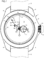
- the watch 1 may include, for wearing on the wrist, a bracelet 3 (in dotted line on the FIG.1 ) which is fixed on the middle part 2 between horns 4 formed projecting thereon.
- the middle part 2 is circular in outline, but this form is not limiting. In particular, this contour could be rectangular (eg square).
- the middle 2 defines an interior space.
- the watch 1 comprises, to close this interior space, an ice and a bottom (not shown), fixed on either side of the middle part 2.
- the watch 1 is equipped with a dial 6 provided with a scale 7.
- the graduation 7 includes indexes 8 for each hour and intermediate indexes 9 for each minute. Intermediate indexes 9 minutes are preferably smaller than the indexes 8 hours.
- the hour indexes 8 are not figurative. However, alternatively, the indexes 8 of the hours could be figurative, and be in the form of numbers (eg Roman, Arabic, Gothic, Greek). Be that as it may, the graduation includes a 12-hour index, indicating midnight and noon for hours, and indicating the zero of minutes and seconds.
- the watch 1 comprises a watch movement (hereinafter simply called “movement”), which comprises a plate intended to be housed in the middle part 2 being fixed thereto, e.g. by means of screws. Platinum forms a support for various mechanisms such as cog, exhaust, transmission, timer, winding (non exhaustive list).
- movement a watch movement
- Platinum forms a support for various mechanisms such as cog, exhaust, transmission, timer, winding (non exhaustive list).
- the movement comprises a timer wheel 11, which includes an hour wheel and a minute wheel (not shown) and a wheel 12 seconds.
- the mobile 11 timer is rotated about an axis A1.
- the mobile 11 timer is rotated by a motor device (not shown). It is preferable that the energy source is a mainspring associated with a balance spring regulator. Nevertheless, that the energy source is a battery associated with a quartz regulator would not be outside the scope of the present invention.
- the watch 1 comprises an hour hand and a minute hand (not shown), respectively for displaying the hours and minutes.
- the watch 1 further comprises a second hand 15 (also called “second hand” or simply “second hand”), coupled to the wheel 12 seconds.
- a second hand 15 also called “second hand” or simply “second hand”
- the second hand 12 is rotated, by the mobile 11 timer, about an axis A2 around which it performs a complete revolution in one minute.
- the second hand 15 is a large second hand in the center, its axis A2 of rotation coinciding with the central axis of the dial 6.
- the second hand 15 has a distal end 16 which travels, during the rotation of the needle 15, the dial 6 passing successively to the right of each index 8, 9 of the graduation 7.
- the second hand 15 is mounted (eg driven) on a second shaft 17 which extends along the axis A2.
- the shaft 17 seconds comprises an upper section 18, on which is mounted the second needle 15, and a lower section 19.
- a pinion 20 which meshes the wheel 12 seconds. More specifically, as illustrated on the FIG.3 , the pinion 20 is mounted on the lower section 19 of the shaft 17 seconds.
- the lower section 19 of the second shaft 17 is provided with one or more larger diameter bead (s) 21 on which the pinion 20 is fitted. This results in a decrease in the interface between the second shaft 17 and the pinion 20.
- the shaft 17 seconds and the pinion 20 are integral in rotation as the shaft 17 seconds is not subjected to any driving torque (or resistant) applied independently of the pinion 20.
- the watch 1 is equipped with a watchmaking mechanism 22 for resetting the second.
- the second hand 15 is detached from the mobile 11 timer and reset to the right of the index of twelve hours (that is to say zero) when a time reset is initiated by the wearer, in particular by pulling on the crown 14.
- the mechanism 22 for resetting the second comprises a cam 23 integral in rotation with the second shaft 17 and whose peripheral edge forms a path 24 of cam.
- the cam 23 is an insert mounted tight (typically by driving) on the shaft 17 seconds.
- the cam 23 is fitted on the upper section 18 of the shaft 17 seconds. Its height position is fixed by a flange 25 formed on the shaft 17 seconds at the junction between the upper section 18 and the lower section 19, and against which is wedged the cam 23.
- the cam 23 is in the form of a spiral: the cam path 24 extends spirally about the axis A2 (that is to say around the shaft 17 seconds) from an end 26 internal (near axis A2), to an outer end 27 (away from the axis A2).
- the cam path 24 is smooth, without asperity.
- the inner end 26 and the outer end 27 are interconnected by an abutment surface 28 which extends substantially radially with respect to the seconds shaft.
- an abutment surface 28 which extends substantially radially with respect to the seconds shaft.
- the cam 23 is advantageously a metal part, e.g. in steel. It is preferably perforated, to be light and to have a low moment of inertia.
- the cam follower 30 is eg. in the form of a lug which protrudes at one end 31 free of the hammer, away from the axis A3 hammer.
- the cam follower 30 is advantageously made of a material with a low coefficient of friction, e.g. in a plastic material (in particular polytetrafluoroethylene, also known under the names PTFE and Teflon®), or in a gemstone (especially ruby).
- the follower 30 of cam is advantageously fixed rigidly (of releasably) on the hammer 29.
- the hammer 29 and the cam follower 30 may form a one-piece member, formed from a single machined piece.
- the hammer 29 In normal operation of the watch 1, the hammer 29 is in its disengaged position. In this case, the second hand 15 is integral with the second shaft 17, pinion 20 meshes the wheel 12 seconds.
- the angular end position of the second hand (zero position) is determined by the abutment of the cam follower against the abutment surface 28. In this position, illustrated on the FIG.7 (And more particularly in the middle medallion in the middle down), the rotation of the cam 23 (and thus of the second shaft 17 and the seconds hand 15) is stopped.
- the support of the cam follower on the cam path 24 is provided by a lever effect exerted on the hammer 29, which tends to rotate it (here clockwise) about the hammer axis A3.
- the mechanism 22 comprises a hammer spring 32.
- This hammer spring 32 is provided with a fixed head 33 and an elastic blade 34 which urges the hammer 29 towards its engaged position.
- the hammer 29 carries a projecting primary pin 35, against which the blade 34 of the spring is in permanent support.
- the leverage exerted on the hammer 29 by the elastic blade 34 of the hammer spring 32 via the primary pin 35 is illustrated by the black arrow at the top on the FIG.5 .
- the induced rotation of the hammer 29 is indicated by the black arrow in the middle of the FIG.5 .
- This rotation brings the cam follower 30 into contact with the cam path 24. Since the cam and smooth path 24, and the cam follower 30 has a low coefficient of friction, it can freely slide on the cam path 24.
- the cam 23, the hammer 29 and the hammer spring 32 are configured so that, irrespective of the angular position of the cam 23, the torque induced thereon by the cam follower 30 is always greater than the threshold beyond of which a sliding occurs at the interface between the shaft 17 seconds and the pinion 20.
- the actuator 36 is in the form of a rod mounted in translation (but it could be mounted in rotation).
- the hammer 29 carries a secondary pin 37 protruding against which a shoulder 38 formed on the actuator 36 is supported in position restraint of it.
- This shoulder 38 is e.g. defined by a claw 39 formed projecting at one end of the actuator 36.
- the movement of the actuator 36 is controlled by the crown, and more precisely by the crown 14.
- the crown 14 places the actuator 36 in the retaining position, which maintains the hammer 29 in the disengaged position and allows the rotation of the shaft 17 of seconds (and with it of the second hand 15) induced by the mobile 11 timer.
- the latter places the actuator 36 in the release position (horizontal black arrow, top left on the FIG.5 ), which allows the hammer spring 32 to exert its leverage on the hammer 29 to apply the cam follower 30 to the cam path 24.
- the mechanism 22 for resetting the second comprises a system 40 with a non-return ratchet which only allows the rotation of the cam 23 in one direction (the direction time in the example shown).
- the ratchet system 40 comprises a toothed wheel 41 mounted coaxially with the shaft 17 of seconds, and a pawl 42 carried by the cam 23 and which drives the toothed wheel 41.
- the toothed wheel 41 is rotatably connected to the pinion 20, as the case may be (as illustrated on FIG. FIG.2 ) via a doll 43 driven on the pinion 20.
- the doll 43 is integrated in a transmission wheel 44 meshing eg. a ringing mobile (not shown).
- the toothed wheel 41 is Breguet type tooth, that is to say that the teeth are triangular and asymmetrical.
- the toothed wheel 41 comprises sixty teeth, which each index, via the pawl 42, a determined position of the seconds hand (which is then called "jumping") corresponding to each of the sixty seconds contained in a minute.
- the positions of the second hand are separated from each other by an angle of 6 °.
- the pawl 42 is biased toward the toothed wheel 41 by means of a spring blade 45 also carried by the cam 23.
- the shaft 17 of the seconds (and with it the second hand 15) is rotationally fixed to the pinion 20, which, engaged by the mobile 11 timer, drives it in rotation about the axis A2.
- the seconds hand 15 acts as a second hand and provides the wearer with an indication of seconds elapsed in the current minute.
- the second hand 15 is then in its end position stroke, and is substantially at the right of the index twelve twelve hours on the scale 7 of the dial 6.
- the pawl 42 is positioned between two successive teeth of the toothed wheel 41, and thus blocks any bounce of the needle when it reaches the end of the race, for the benefit of the accuracy of the reset.
- the second hand 15, at the end of the race is not exactly at the right of the index twelve twelve hours.
- the axis A3 of hammer is defined by a shaft 46 provided with an eccentric 47.
- the rotation of the eccentric 47 causes the hammer 29 to be debated by adjusting the angular end position of the second hand 15 (as suggested by the various positions outlined in dotted line on the FIG.8 ).
- the rotation of eccentric 47 is e.g. performed by a manual action, typically by means of a screwdriver.
- a manual action typically by means of a screwdriver.
- an end of the eccentric 47 is shaped as a recess 48 (eg a slot) for a screwdriver.
- a recess 48 eg a slot
- the mechanism 22 for resetting seconds that has just been described has the following advantages.
- the present mechanism 22 is of simpler architecture.
- the hammer 29, in particular, is of less complex shape.
- the absence of heel, and the presence of the cam follower 30 which, at the end of the stroke, merely abuts against the abutment surface 28, avoids the rebounds of the second hand 15, in favor of the reliability of the mechanism 22 .
- the rebounds are also prevented by the ratchet system 40, which provides unidirectional rotation of the second hand during its reset.
- this mechanism 22 is lightweight, compact, and easy to manufacture.
Abstract
L'invention concerne un mécanisme (22) horloger de remise à zéro de la seconde, qui comprend :
- Un arbre (17) des secondes ;
- Une aiguille (15) trotteuse ;
- Une came (23) formant un chemin (24) de came en colimaçon qui s'étend en spirale autour de l'arbre (17) des secondes depuis une extrémité (26) interne jusqu'à une extrémité (27) externe reliées entre elles par une surface (28) de butée radiale ;
- Un marteau (29) portant un suiveur (30) de came, monté en rotation autour d'un axe (A3) de marteau entre une position débrayée dans laquelle le suiveur (30) de came est écarté du chemin (24) de came, et une position embrayée dans laquelle le suiveur (30) de came est en appui sur le chemin (24) de came ;
- un système à cliquet anti-retour comprenant une roue (41) dentée et un cliquet (42) qui attaque la roue (41) dentée.

- A tree (17) seconds;
- A needle (15) second hand;
- A cam (23) forming a spiral cam path (24) which spirals around the second shaft (17) from an inner end (26) to an outer end (27) connected between they by a surface (28) of radial abutment;
- A hammer (29) carrying a cam follower (30) rotatably mounted about a hammer axis (A3) between a disengaged position in which the cam follower (30) is moved away from the cam path (24). and an engaged position in which the cam follower (30) bears on the cam path (24);
- A non-return ratchet system comprising a toothed wheel (41) and a ratchet (42) which engages the toothed wheel (41).
Description
L'invention a trait au domaine de l'horlogerie. Elle concerne, plus précisément, un mécanisme horloger de remise à zéro de la seconde ainsi qu'une montre équipée d'un tel mécanisme.The invention relates to the field of watchmaking. It concerns, more precisely, a watch mechanism for resetting the second and a watch equipped with such a mechanism.
On peut trouver un mécanisme de remise à zéro de la seconde :
- dans la plupart des montres à chronographe,
- et dans certaines montres pourvues d'une aiguille trotteuse (également appelée aiguille des secondes, ou plus simplement trotteuse) et dont le réglage de l'heure est accompagné d'une remise à zéro automatique de la trotteuse.
- in most chronograph watches,
- and in some watches provided with a second-hand hand (also called seconds hand, or more simply second hand) and whose time setting is accompanied by an automatic reset of the second hand.
Classiquement, un tel mécanisme comprend (outre l'aiguille trotteuse et son arbre des secondes) :
- une came solidaire en rotation de l'arbre des secondes et dont un bord périphérique forme un chemin de came ;
- un marteau portant un suiveur de came, ce marteau étant monté en rotation autour d'un axe de marteau entre une position débrayée dans laquelle le suiveur de came est écarté du chemin de came, et une position embrayée dans laquelle le suiveur de came est en appui sur le chemin de came pour produire un couple moteur sur l'arbre des secondes.
- a cam integral in rotation with the seconds shaft and a peripheral edge of which forms a cam path;
- a hammer carrying a cam follower, which hammer is rotatably mounted about a hammer axis between a disengaged position in which the cam follower is moved away from the cam path, and an engaged position in which the cam follower is in press on the cam path to produce a motor torque on the seconds shaft.
La came présente ordinairement une forme de coeur, raison pour laquelle on l'appelle simplement « coeur », comme il apparaît dans le manuel de référence de
Dans les chronographes, le marteau est une pièce complexe pourvue de plusieurs suiveurs de cames qui viennent frapper simultanément plusieurs cames respectives, solidaires de l'aiguille des heures, de l'aiguille des minutes, de l'aiguille des secondes (et, plus occasionnellement, d'une aiguille des dixièmes).In chronographs, the hammer is a complex piece with several cam followers that strike several respective cams, integral with the hour hand, the minute hand, the second hand (and, more occasionally, a tenth needle).
Dans les montres à remise à zéro automatique de la trotteuse, comme celle décrite dans le brevet européen
Dans tous les cas, le suiveur de came est ordinairement formé par une extrémité du marteau en forme de sabot de cheval, qui vient, en fin de course (angulaire ou linéaire), s'appliquer contre un bossage double formé sur le coeur pour en assurer le maintien dans une position stable correspondant à la remise à zéro de la trotteuse.In all cases, the cam follower is usually formed by one end of the hammer in the shape of a horse shoe, which comes, end of stroke (angular or linear), against a double boss formed on the heart to maintain in a stable position corresponding to the reset of the second hand.
Ce type de mécanisme, très largement répandu, souffre cependant de plusieurs inconvénients.This type of mechanism, very widespread, however, suffers from several disadvantages.
Premièrement, la position de la trotteuse lors de la remise à zéro est, le plus souvent, assez aléatoire et manque de précision. Cela est particulièrement préjudiciable dans le cas d'une aiguille sautante, qui est supposée se trouver à chaque seconde dans une position angulaire bien précise (chaque position angulaire étant écartée de la suivante de 6°).First, the position of the second hand during the reset is, in most cases, rather random and lacks precision. This is particularly detrimental in the case of a jumping needle, which is supposed to be every second in a precise angular position (each angular position being spaced from the next 6 °).
Deuxièmement, compte tenu de la géométrie respective du coeur et du marteau, les efforts de frottement à leur interface ne sont pas constants. Il en résulte une usure non uniforme de ces pièces, préjudiciable à long terme sur la fiabilité du mécanisme.Secondly, given the respective geometry of the core and the hammer, the friction forces at their interface are not constant. This results in non-uniform wear of these parts, detrimental to the long-term reliability of the mechanism.
Troisièmement, dans certaines positions angulaires du coeur, le marteau frotte sur elle par une arête vive, comme illustré sur la FIG.11.29 du manuel précité, ce qui accroît la concentration de contraintes, l'usure et la fatigue mécanique de ces pièces.Third, in certain angular positions of the core, the hammer rubs on it by a sharp edge, as illustrated in FIG.11.29 of the aforementioned manual, which increases the stress concentration, wear and mechanical fatigue of these parts.
Quatrièmement, l'élan acquis par le coeur lors de sa rotation fait qu'il ne se trouve pas immédiatement bloqué en fin de course par l'appui de l'extrémité du marteau dans l'arbre des secondes, mais demeure, avant de s'immobiliser, animé d'oscillations amorties qui nuisent à la perception de précision attendue par un utilisateur averti.Fourthly, the momentum acquired by the heart during its rotation causes it not to be immediately blocked at the end of the race by the support of the end of the hammer in the seconds tree, but remains, before s immobilize, animated by damped oscillations which impede the perception of precision expected by an informed user.
Cinquièmement, la complexité des mécanismes connus les rend lourds et de fabrication fastidieuse.Fifth, the complexity of known mechanisms makes them cumbersome and time-consuming.
Un premier objectif est de proposer un mécanisme de remise à zéro de la seconde qui procure une position précise de la trotteuse, exactement en regard d'une graduation prédéterminée du cadran (typiquement un index de douze heures).A first objective is to propose a mechanism for resetting the second which provides a precise position of the second hand, exactly opposite a predetermined graduation of the dial (typically a twelve-hour index).
Un deuxième objectif ayant une plus grande fiabilité, et par conséquent une plus grande longévité.A second objective with greater reliability, and therefore longer life.
Un troisième objectif est de proposer un mécanisme de remise à zéro de la seconde d'architecture plus simple (et donc moins encombrante, plus légère et de fabrication plus facile) que les mécanismes connus.A third objective is to propose a mechanism for resetting the second architecture simpler (and therefore less cumbersome, lighter and easier to manufacture) than the known mechanisms.
Pour atteindre tout ou partie des objectifs précités, il est proposé, en premier lieu, un mécanisme horloger de remise à zéro de la seconde, qui comprend :
- un arbre des secondes ;
- une aiguille trotteuse solidaire en rotation de l'arbre des secondes ;
- une came solidaire en rotation de l'arbre des secondes et dont un bord périphérique forme un chemin de came ;
- un marteau pourvu d'un suiveur de came, ce marteau étant monté en rotation autour d'un axe de marteau entre une position débrayée dans laquelle le suiveur de came est écarté du chemin de came, et une position embrayée dans laquelle le suiveur de came est en appui sur le chemin de came pour produire un couple moteur sur l'arbre des secondes ; ce mécanisme étant remarquable :
- en ce que la came se présente sous forme d'un colimaçon, le chemin de came s'étendant en spirale autour de l'arbre des secondes depuis une extrémité interne jusqu'à une extrémité externe reliées entre elles par une surface de butée qui s'étend sensiblement radialement par rapport à l'arbre des secondes et contre laquelle vient buter le suiveur de came dans une position angulaire de fin de course de l'aiguille trotteuse ;
- en ce qu'il comprend un système à cliquet anti-retour comprenant une roue dentée montée sur l'arbre des secondes, et un cliquet porté par la came et qui attaque la roue dentée.
- a tree of seconds;
- a second hand running in rotation with the seconds tree;
- a cam integral in rotation with the seconds shaft and a peripheral edge of which forms a cam path;
- a hammer provided with a cam follower, which hammer is rotatably mounted about a hammer axis between a disengaged position in which the cam follower is moved away from the cam path, and an engaged position in which the cam follower is in support on the cam path to produce a motor torque on the seconds shaft; this mechanism being remarkable:
- in that the cam is in the form of a spiral, the cam path spiraling around the seconds shaft from an inner end to an outer end interconnected by an abutment surface which 'extends substantially radially with respect to the seconds shaft and against which abuts the cam follower in an angular end position of the second hand;
- in that it comprises a non-return ratchet system comprising a toothed wheel mounted on the seconds shaft, and a pawl carried by the cam and which drives the toothed wheel.
Grâce à cette architecture, le mécanisme demeure efficace tout en étant assez simple, léger et peu encombrant. Lors de la remise à zéro, l'aiguille des secondes peut retrouver une position précise en regard d'une graduation.Thanks to this architecture, the mechanism remains efficient while being quite simple, light and compact. When resetting, the second hand can find a precise position next to a graduation.
Diverses caractéristiques supplémentaires peuvent être prévues, seules ou en combinaison. Ainsi, par exemple :
- le mécanisme peut comprendre un ressort de marteau pourvu d'une tête fixe et d'une lame élastique qui sollicite le marteau vers sa position embrayée.
- le marteau peut porter un pion primaire en saillie, contre lequel la lame du ressort est en appui permanent.
- le mécanisme peut comprendre un actionneur monté mobile entre une position de retenue dans laquelle il place le marteau dans sa position débrayée, et une position de libération dans laquelle il permet au marteau d'occuper sa position embrayée.
- le marteau peut porter un pion secondaire en saillie, contre lequel un épaulement formé sur l'actionneur est en appui en position de retenue de celui-ci.
- le mécanisme peut comprendre un système à cliquet anti-retour qui n'autorise la rotation de la came que dans un sens.
- le système à cliquet peut comprendre une roue dentée montée de manière coaxiale à l'arbre des secondes, et un cliquet porté par la came et qui attaque la roue dentée.
- l'axe de marteau peut être pourvu d'un excentrique dont la rotation fait débattre le marteau en ajustant la position angulaire de fin de course de l'aiguille trotteuse.
- the mechanism may comprise a hammer spring provided with a fixed head and an elastic blade which urges the hammer towards its engaged position.
- the hammer may carry a projecting primary pin, against which the leaf spring is in permanent support.
- the mechanism may comprise an actuator movably mounted between a retaining position in which it places the hammer in its disengaged position, and a release position in which it allows the hammer to occupy its engaged position.
- the hammer may carry a secondary projection pin, against which a shoulder formed on the actuator is supported in the retaining position thereof.
- the mechanism may comprise a non-return ratchet system which allows rotation of the cam only in one direction.
- the ratchet system may comprise a gear wheel mounted coaxially with the second shaft, and a pawl carried by the cam and engaging the gear wheel.
- the hammer axle may be provided with an eccentric whose rotation causes the hammer to be debated by adjusting the angular end position of the second hand.
Il est proposé, en deuxième lieu, une montre équipée d'un tel mécanisme.It is proposed, secondly, a watch equipped with such a mechanism.
Selon un mode préféré de réalisation, la montre peut être équipée d'un cadran muni d'une graduation incluant un index de douze heures avec laquelle l'aiguille est sensiblement alignée lorsqu'elle est en position angulaire de fin de course.According to a preferred embodiment, the watch may be equipped with a dial provided with a graduation including a twelve-hour index with which the needle is substantially aligned when in angular end position.
D'autres objets et avantages de l'invention apparaîtront à la lumière de la description d'un mode de réalisation, faite ci-après en référence aux dessins annexés dans lesquels :
- la
FIG.1 est une vue en plan d'une montre équipée d'un mécanisme de remise à zéro de la seconde ; - la
FIG.2 est une vue de détail en perspective du mécanisme de remise à zéro de la seconde ; - la
FIG.3 est une vue de détail en coupe du mécanisme de remise à zéro, selon le plan de coupe III-III de laFIG.1 ; - les
FIG.4 ,FIG.5 ,FIG.6 ,FIG.7 etFIG.8 sont des vues de détail en plan, à plus grande échelle, du mécanisme de remise à zéro de la seconde et illustrant diverses phases de son fonctionnement.
- the
FIG.1 is a plan view of a watch equipped with a reset mechanism of the second; - the
FIG.2 is a detailed perspective view of the reset mechanism of the second; - the
FIG.3 is a sectional detail view of the reset mechanism, according to the sectional plane III-III of theFIG.1 ; - the
FIG.4 ,FIG.5 ,FIG.6 ,FIG.7 andFIG.8 are enlarged plan views of the reset mechanism of the second and illustrate various phases of its operation.
Sur la
La montre 1 peut comprendre, pour le port au poignet, un bracelet 3 (en trait mixte sur la
Dans l'exemple illustré, la carrure 2 est à contour circulaire, mais cette forme n'est pas limitative. En particulier, ce contour pourrait être rectangulaire (par ex. carré).In the example shown, the
La carrure 2 définit un espace 5 intérieur. La montre 1 comprend, pour fermer cet espace 5 intérieur, une glace et un fond (non représentés), fixés de part et d'autre de la carrure 2.The middle 2 defines an interior space. The
La montre 1 est équipée d'un cadran 6 muni d'une graduation 7. Selon un mode de réalisation illustré sur les dessins, et plus particulièrement sur la
Dans l'exemple illustré, les index 8 des heures ne sont pas figuratifs. Cependant, en variante, les index 8 des heures pourraient être figuratifs, et se présenter sous forme de chiffres (par ex. romains, arabes, gothiques, grecs). Quoiqu'il en soit, la graduation comprend un index 10 des douze heures, indiquant minuit et midi pour les heures, et indiquant le zéro des minutes et des secondes.In the example shown, the
La montre 1 comporte un mouvement d'horlogerie (ci-après simplement dénommé « mouvement »), qui comprend une platine destinée à venir se loger dans la carrure 2 en étant fixée à celle-ci, par ex. au moyen de vis. La platine forme un support pour divers mécanismes tels que rouage, échappement, transmission, minuterie, remontoir (liste non exhaustive).The
Le mouvement comprend un mobile 11 de minuterie, qui inclut une roue des heures et une roue des minutes (non représentée) ainsi qu'une roue 12 des secondes. Le mobile 11 de minuterie est monté en rotation autour d'un axe A1.The movement comprises a
Le mobile 11 de minuterie est entraîné en rotation par un dispositif moteur (non représenté). Il est préférable que la source d'énergie soit un ressort de barillet associé à un régulateur à balancier spiral. Néanmoins, que la source d'énergie soit une pile associée à un régulateur à quartz ne sortirait pas du cadre de la présente invention.The mobile 11 timer is rotated by a motor device (not shown). It is preferable that the energy source is a mainspring associated with a balance spring regulator. Nevertheless, that the energy source is a battery associated with a quartz regulator would not be outside the scope of the present invention.
La montre 1 comprend une aiguille des heures et une aiguille des minutes (non représentées), respectivement pour l'affichage des heures et des minutes.The
La montre est équipée d'un mécanisme 13 de remise à l'heure, qui inclut un remontoir couplé aux aiguilles des heures et des minutes. Ce remontoir comprend notamment une couronne 14 accessible pour le porteur sur un côté de la carrure 2. La couronne 14 est mobile entre :
- une position rentrée, illustrée en trait plein sur la
FIG.1 et dans laquelle la couronne 14 est désaccouplée des aiguilles des heures et des minutes, qui demeurent entraînées en rotation par le mobile 11 de minuterie, et - une position sortie, illustrée en pointillés sur la
FIG.1 et dans laquelle la couronne 14 est accouplée aux aiguilles pour permettre la remise à l'heure.
- a retracted position, illustrated in solid lines on the
FIG.1 and wherein thering 14 is uncoupled from the hour and minute hands, which remain rotated by thetimer wheel 11, and - an exit position, illustrated in dotted lines on the
FIG.1 and wherein thering 14 is coupled to the needles to allow the time setting.
Comme illustré, la montre 1 comprend en outre une aiguille 15 des secondes (également appelée « aiguille trotteuse » ou plus simplement « trotteuse »), couplée à la roue 12 des secondes.As illustrated, the
L'aiguille 12 des secondes est entraînée en rotation, par le mobile 11 de minuterie, autour d'un axe A2 autour duquel elle effectue une révolution complète en une minute. Dans l'exemple illustré, l'aiguille 15 des secondes est une grande trotteuse au centre, son axe A2 de rotation étant confondu avec l'axe central du cadran 6.The
L'aiguille 15 des secondes présente une extrémité 16 distale qui parcourt, lors de la rotation de l'aiguille 15, le cadran 6 en passant successivement au droit de chaque index 8, 9 de la graduation 7.The
L'aiguille 15 des secondes est montée (en étant par ex. chassée) sur un arbre 17 des secondes qui s'étend selon l'axe A2. Comme on le voit sur la
Sur l'arbre 17 des secondes est monté un pignon 20 qui engrène la roue 12 des secondes. Plus précisément, comme illustré sur la
Comme on le voit sur la
De la sorte, l'arbre 17 des secondes et le pignon 20 sont solidaires en rotation tant que l'arbre 17 des secondes n'est soumis à aucun couple moteur (ou résistant) appliqué indépendamment du pignon 20.In this way, the
Dès lors, en revanche, qu'un couple moteur (ou résistant) dépassant un seuil prédéterminé est appliqué à l'arbre 17 des secondes indépendamment du pignon 20, l'arbre 17 des secondes peut tourner librement par rapport au pignon 20, qui demeure fixe car engrenant le mobile 11 de minuterie. Dans ce cas, il se produit un glissement à l'interface entre l'arbre 17 des secondes et le pignon 20.Therefore, on the other hand, that a driving torque (or resistant) exceeding a predetermined threshold is applied to the
La montre 1 est équipée d'un mécanisme 22 horloger de remise à zéro de la seconde. Par ce mécanisme 22, l'aiguille 15 des secondes est désolidarisée du mobile 11 de minuterie et remise au droit de l'index 10 des douze heures (c'est-à-dire à zéro) lorsqu'une remise à l'heure est initiée par le porteur, notamment par traction sur la couronne 14.The
Outre l'arbre 17 des secondes et l'aiguille 15 des secondes déjà évoqués, le mécanisme 22 de remise à zéro de la seconde comprend une came 23 solidaire en rotation de l'arbre 17 des secondes et dont un bord périphérique forme un chemin 24 de came.In addition to the
Selon un mode préféré de réalisation illustré sur les dessins, et notamment sur la
Dans l'exemple illustré sur la
Comme on le voit bien sur les
L'extrémité 26 interne et l'extrémité 27 externe sont reliées entre elles par une surface 28 de butée qui s'étend sensiblement radialement par rapport à l'arbre des secondes. Lorsque vu de face (c'est-à-dire suivant l'axe A2), le contour de la came 23 est ainsi similaire au contour de la coquille d'un céphalopode marin de l'espèce nautilus.The
La came 23 est avantageusement une pièce métallique, par ex. en acier. Elle est de préférence ajourée, afin d'être légère et de présenter un faible moment d'inertie.The
Le mécanisme 22 de remise à zéro de la seconde comprend, par ailleurs, un marteau 29 pourvu d'un suiveur 30 de came. Ce marteau 29 est monté en rotation autour d'un axe A3 de marteau entre :
- une position débrayée (
FIG.4 ,FIG.8 ) dans laquelle le suiveur 30 de came est écarté du chemin de came, et - une position embrayée (
FIG.5 ,FIG.6 ,FIG.7 ) dans laquelle le suiveur 30 de came est en appui sur le chemin 24 de came pour produire un couple moteur sur l'arbre 17 des secondes.
- a disengaged position (
FIG.4 ,FIG.8 ) in which thecam follower 30 is moved away from the cam path, and - a clutched position (
FIG.5 ,FIG.6 ,FIG.7 ) in which thecam follower 30 is resting on thecam path 24 to produce a motor torque on thesecond shaft 17.
Le suiveur 30 de came se présente par ex. sous forme d'un ergot qui fait saillie à une extrémité 31 libre du marteau, à distance de l'axe A3 de marteau. Le suiveur 30 de came est avantageusement réalisé dans un matériau à faible coefficient de frottement, par ex. dans une matière plastique (notamment en polytétrafluoroéthylène, également connu sous les dénominations PTFE et Téflon®), ou dans une pierre précieuse (notamment en rubis). Le suiveur 30 de came est avantageusement fixé rigidement (de manière indémontable) sur le marteau 29. Alternativement, le marteau 29 et le suiveur 30 de came peuvent former un élément monobloc, formée à partir d'une pièce unique usinée.The
En fonctionnement normal de la montre 1, le marteau 29 est dans sa position débrayée. Dans ce cas, l'aiguille 15 des secondes est solidaire, avec l'arbre 17 des secondes, du pignon 20 qu'engrène la roue 12 des secondes.In normal operation of the
Lorsqu'une remise à l'heure est initiée par l'utilisateur, typiquement par traction sur la couronne 14, le marteau 29 est déplacé vers sa position embrayée pour entraîner en rotation, via le suiveur 30 de came en appui sur le chemin 24 de came, l'arbre 17 des secondes (et avec lui l'aiguille 15 des secondes) - ce indépendamment du pignon 20 - jusqu'à amener l'aiguille 15 des secondes dans une position angulaire de fin de course où elle se trouve sensiblement au droit de l'index 10 des douze heures (remise à zéro).When a time reset is initiated by the user, typically by pulling on the
La position angulaire de fin de course de l'aiguille 15 des secondes (position à zéro) est déterminée par la venue en butée du suiveur 30 de came contre la surface 28 de butée. Dans cette position, illustrée sur la
L'appui du suiveur 30 de came sur le chemin 24 de came est procuré par un effet de levier exercé sur le marteau 29, qui tend à le faire pivoter (ici dans le sens horaire) autour de l'axe A3 de marteau.The support of the cam follower on the
A cet effet, le mécanisme 22 comprend un ressort 32 de marteau. Ce ressort 32 de marteau est pourvu d'une tête 33 fixe et d'une lame 34 élastique qui sollicite le marteau 29 vers sa position embrayée.For this purpose, the
Selon un mode de réalisation, le marteau 29 porte un pion 35 primaire en saillie, contre lequel la lame 34 du ressort est en appui permanent. L'effet de levier exercé sur le marteau 29 par la lame 34 élastique du ressort 32 de marteau via le pion 35 primaire est illustré par la flèche noire en haut sur la
La rotation induite du marteau 29 est indiquée par la flèche noire au milieu de la
L'effet de levier appliqué par le ressort 32 de marteau sur le marteau 29 se poursuivant, le suiveur 30 de came glisse sur la surface 24 de came en exerçant sur elle (et donc sur la came 23) un effort non concourant avec l'axe A3 des secondes, d'où il résulte un couple moteur induit sur la came 23 (et donc sur l'arbre 17 des secondes).As the lever effect applied by the
La came 23, le marteau 29 et le ressort 32 de marteau sont configurés pour que, quelle que soit la position angulaire de la came 23, le couple induit sur celle-ci par le suiveur 30 de came soit toujours supérieur au seuil au-delà duquel se produit un glissement à l'interface entre l'arbre 17 des secondes et le pignon 20.The
Il en résulte que l'arbre 17 des secondes, et avec lui l'aiguille 15 des secondes, est entraîné en rotation autour de l'axe A2, comme illustré par la flèche noire en bas à droite sur la
Selon un mode de réalisation illustré sur les dessins, le mécanisme 22 de remise à zéro de la seconde comprend un actionneur 36 monté mobile entre :
- une position de retenue dans laquelle l'actionneur 36
place le marteau 29 dans sa position débrayée (FIG.4 ,FIG.8 ), et - une position de libération dans laquelle l'actionneur 36 permet au marteau 29 d'occuper sa position embrayée (
FIG.5 ,FIG.6 ,FIG.7 ).
- a holding position in which the
actuator 36 places thehammer 29 in its disengaged position (FIG.4 ,FIG.8 ), and - a release position in which the
actuator 36 allows thehammer 29 to occupy its engaged position (FIG.5 ,FIG.6 ,FIG.7 ).
Dans l'exemple illustré, l'actionneur 36 se présente sous forme d'une tige montée en translation (mais elle pourrait être montée en rotation).In the illustrated example, the
Le marteau 29 porte quant à lui un pion 37 secondaire en saillie, contre lequel un épaulement 38 formé sur l'actionneur 36 est en appui en position de retenue de celui-ci. Cet épaulement 38 est par ex. défini par une griffe 39 formée en saillie à une extrémité de l'actionneur 36.The
Le mouvement de l'actionneur 36 est commandé par le remontoir, et plus précisément par la couronne 14. Ainsi, en position rentrée de la couronne 14, celle-ci place l'actionneur 36 en position de retenue, ce qui maintient le marteau 29 en position débrayée et permet la rotation de l'arbre 17 des secondes (et avec lui de l'aiguille 15 des secondes) induite par le mobile 11 de minuterie.The movement of the
En revanche, en position sortie de la couronne 14, celle-ci place l'actionneur 36 en position de libération (flèche noire horizontale, en haut à gauche sur la
Selon un mode préféré de réalisation illustré notamment sur la
Le système 40 à cliquet comprend une roue 41 dentée montée de manière coaxiale à l'arbre 17 des secondes, et un cliquet 42 porté par la came 23 et qui attaque la roue 41 dentée.The
Plus précisément, la roue 41 dentée est solidaire en rotation du pignon 20, le cas échéant (comme illustré sur la
Selon un mode préféré de réalisation, la roue 41 dentée est à denture de type Breguet, c'est-à-dire que les dents sont triangulaires et asymétriques. Dans l'exemple illustré, la roue 41 dentée comprend soixante dents, qui indexent chacune, via le cliquet 42, une position déterminée de l'aiguille 15 des secondes (qui est alors dite « sautante ») correspondant à chacune des soixante secondes contenues dans une minute. En d'autres termes, les positions de l'aiguille 15 des secondes sont séparées les unes des autres d'un angle de 6°.According to a preferred embodiment, the
Dans l'exemple illustré sur la
Le fonctionnement du mécanisme 22 de remise à zéro de la seconde est le suivant.The operation of the
En position rentrée de la couronne 14, celle-ci maintient l'actionneur 36 en position de retenue, ce qui maintient le marteau 29 (et le suiveur 30 de came) en position débrayée, à l'écart de la came 23.In the retracted position of the
L'arbre 17 des secondes (et avec lui l'aiguille 15 des secondes) est solidaire en rotation du pignon 20, qui, engrené par le mobile 11 de minuterie, l'entraîne en rotation autour de l'axe A2. Dans ces conditions, l'aiguille 15 des secondes joue son rôle de trotteuse et fournit au porteur l'indication des secondes écoulées dans la minute en cours.The
En position sortie de la couronne 14, celle-ci place l'actionneur 36 en position de libération, ce qui permet au marteau 29 de se déplacer, sous l'effet de levier procuré par le ressort 32 de marteau, vers sa position embrayée, dans laquelle le suiveur 30 de came est en appui glissant contre le chemin 24 de came.In the output position of the
L'appui glissant du suiveur 30 de came contre le chemin 24 de came induit, comme expliqué ci-dessus, la rotation de la came 23, et avec elle de l'arbre 17 des secondes (qui glisse à son interface avec le pignon 20, lequel demeure fixe en rotation autour de l'axe A2 en demeurant engrené par le mobile 11 de minuterie).The sliding support of the
La rotation de la came 23 (dans le sens horaire) et de l'aiguille 15 des secondes, qui lui est solidaire, se poursuit jusqu'à ce que le suiveur 30 de came vienne s'appliquer contre la surface 28 de butée, ce qui stoppe la rotation de la came 23 (et donc de l'arbre 17 des secondes et de l'aiguille 15 des secondes). L'aiguille 15 des secondes est alors dans sa position de fin de course, et se trouve sensiblement au droit de l'index 10 des douze heures sur la graduation 7 du cadran 6. Le cliquet 42 vient se positionner entre deux dents successives de la roue 41 dentée, et bloque ainsi tout rebond de l'aiguille lorsqu'elle parvient en fin de course, au bénéfice de la précision de la remise à zéro.The rotation of the cam 23 (in the clockwise direction) and the
Il se peut que l'aiguille 15 des secondes, en fin de course, ne soit pas exactement au droit de l'index 10 des douze heures.It may be that the
Pour permettre un réglage fin de la position de fin de course de l'aiguille 15 des secondes, et garantir que dans cette position l'aiguille 15 des secondes se trouve exactement au droit de l'index des douze heures, l'axe A3 de marteau est défini par un arbre 46 pourvu d'un excentrique 47.To allow a fine adjustment of the end position of the
La rotation de l'excentrique 47 fait débattre le marteau 29 en ajustant la position angulaire de fin de course de l'aiguille 15 des secondes (comme le suggèrent les différentes positions esquissées en pointillés sur la
La rotation de l'excentrique 47 est par ex. effectuée par une action manuelle, typiquement au moyen d'un tournevis. A cet effet, comme illustré notamment sur la
Dès lors que la couronne 14 est replacée dans sa position rentrée, l'actionneur 37 est replacé dans sa position de retenue (
Il en résulte que la rotation du pignon 20, engrené par le mobile 11 de minuterie (et plus précisément par la roue 12 des secondes) entraîne en rotation l'arbre 17 des secondes, et avec lui l'aiguille 15 des secondes dans le mouvement cyclique ordinaire.As a result, the rotation of the
Le mécanisme 22 de remise à zéro des secondes qui vient d'être décrit présente les avantages suivants.The
Premièrement, en comparaison des mécanismes à coeur connus, le présent mécanisme 22 est d'architecture plus simple. Le marteau 29, en particulier, est de forme moins complexe. L'absence de talon, et la présence du suiveur 30 de came qui, en fin de course, vient simplement buter contre la surface 28 de butée, évite les rebonds de l'aiguille 15 des secondes, au bénéfice de la fiabilité du mécanisme 22.First, in comparison with known heart mechanisms, the
Comme déjà évoqué, les rebonds sont également empêchés par le système 40 à cliquet, qui assure le caractère unidirectionnel de la rotation de l'aiguille 15 des secondes lors de sa remise à zéro.As already mentioned, the rebounds are also prevented by the
Etant plus simple, ce mécanisme 22 est léger, peu encombrant, et de fabrication facile.Being simpler, this
Il en résulte notamment une plus grande fiabilité, et par conséquent une plus grande longévité du mécanisme 22 (et donc de la montre 1).This results in particular greater reliability, and therefore a longer life of the mechanism 22 (and therefore the watch 1).
Claims (10)
Priority Applications (4)
| Application Number | Priority Date | Filing Date | Title |
|---|---|---|---|
| EP17202604.9A EP3486735B1 (en) | 2017-11-20 | 2017-11-20 | Second reset clock mechanism with snail cam |
| US16/178,034 US11163266B2 (en) | 2017-11-20 | 2018-11-01 | Timepiece mechanism for returning the seconds hand to zero with a snail cam |
| JP2018211116A JP6609020B2 (en) | 2017-11-20 | 2018-11-09 | A timer mechanism that zeroes the second hand with a vortex cam |
| CN201811375293.6A CN109814365B (en) | 2017-11-20 | 2018-11-19 | Clock mechanism for zeroing second hand using spiral cam |
Applications Claiming Priority (1)
| Application Number | Priority Date | Filing Date | Title |
|---|---|---|---|
| EP17202604.9A EP3486735B1 (en) | 2017-11-20 | 2017-11-20 | Second reset clock mechanism with snail cam |
Publications (2)
| Publication Number | Publication Date |
|---|---|
| EP3486735A1 true EP3486735A1 (en) | 2019-05-22 |
| EP3486735B1 EP3486735B1 (en) | 2020-09-30 |
Family
ID=60409232
Family Applications (1)
| Application Number | Title | Priority Date | Filing Date |
|---|---|---|---|
| EP17202604.9A Active EP3486735B1 (en) | 2017-11-20 | 2017-11-20 | Second reset clock mechanism with snail cam |
Country Status (4)
| Country | Link |
|---|---|
| US (1) | US11163266B2 (en) |
| EP (1) | EP3486735B1 (en) |
| JP (1) | JP6609020B2 (en) |
| CN (1) | CN109814365B (en) |
Families Citing this family (1)
| Publication number | Priority date | Publication date | Assignee | Title |
|---|---|---|---|---|
| EP3985447A1 (en) * | 2020-10-19 | 2022-04-20 | Glashütter Uhrenbetrieb GmbH | Adjustable lever of a tourbillon mechanism and a method of adjustment |
Citations (4)
| Publication number | Priority date | Publication date | Assignee | Title |
|---|---|---|---|---|
| US377896A (en) * | 1888-02-14 | better | ||
| EP2224294A1 (en) | 2009-02-27 | 2010-09-01 | Glashütter Uhrenbetrieb GmbH | Mechanism for setting the minute hand of a timepiece with automatic return-to-zero of the seconds hand |
| WO2014079736A1 (en) * | 2012-11-22 | 2014-05-30 | Eterna Ag Uhrenfabrik | Minute hand of a timepiece, in particular of a chronograph |
| EP3112956A1 (en) * | 2015-07-01 | 2017-01-04 | Richemont International S.A. | Retrograde chronograph mechanism with rattrapante hand |
Family Cites Families (26)
| Publication number | Priority date | Publication date | Assignee | Title |
|---|---|---|---|---|
| US2322257A (en) * | 1940-05-27 | 1943-06-22 | Stuart John Frederick William | Clock |
| CH544957A (en) * | 1970-03-26 | 1974-01-15 | Mingard Marcel | Oscillating rotary indicator timepiece |
| CH676309B5 (en) * | 1989-03-30 | 1991-07-15 | Phare Jean D Eve Sa Le | |
| JP4296019B2 (en) * | 2003-03-27 | 2009-07-15 | セイコーインスツル株式会社 | Chronograph watch with nulling structure |
| US7961560B2 (en) * | 2005-01-24 | 2011-06-14 | Seiko Epson Corporation | Display device for timepiece, movement, and timepiece |
| EP1777598B1 (en) * | 2005-10-21 | 2012-02-15 | Rolex Sa | Timepiece with a mechanism to measure adjustable predetermined times |
| EP1840677B1 (en) * | 2006-03-28 | 2011-10-26 | Chopard Manufacture SA | Return-to-zero of the seconds hand in a timepiece |
| CH698826B1 (en) * | 2006-03-29 | 2009-11-13 | Girard Perregaux Sa | Movement for a timepiece with retrograde. |
| CH698827B1 (en) * | 2006-08-15 | 2009-11-13 | Chopard Manufacture Sa | Device reset for a timepiece. |
| EP2113817B1 (en) * | 2007-02-22 | 2018-12-26 | ETA SA Manufacture Horlogère Suisse | Chronograph |
| JP6567806B2 (en) * | 2013-05-31 | 2019-08-28 | ロレックス・ソシエテ・アノニムRolex Sa | Clock mechanism for storing and displaying time information |
| EP2824521A3 (en) * | 2013-07-12 | 2016-06-01 | Rolex Sa | Clockwork mechanism, clock movement and timepiece |
| EP2824517A3 (en) * | 2013-07-12 | 2016-06-01 | Rolex Sa | Clockwork mechanism, clock movement and timepiece |
| US9526495B2 (en) * | 2014-06-06 | 2016-12-27 | Ethicon Endo-Surgery, Llc | Articulation control for surgical instruments |
| EP3009893B1 (en) * | 2014-10-13 | 2017-11-29 | Montres Breguet SA | Differential perpetual calendar |
| EP3026506B1 (en) * | 2014-11-26 | 2019-01-16 | The Swatch Group Management Services AG | Timer with speed selector |
| EP3101486B1 (en) * | 2015-06-02 | 2018-10-03 | ETA SA Manufacture Horlogère Suisse | Heart of timepiece or chronograph |
| CH712219A2 (en) * | 2016-03-15 | 2017-09-15 | Chanel Sa Genève | Mechanism for watch movement with retrograde and jumping display. |
| CH712217A2 (en) * | 2016-03-15 | 2017-09-15 | Chanel Sa Genève | Watch movement comprising a retrograde display and a ring of jumping hours. |
| EP3640747A1 (en) * | 2016-07-15 | 2020-04-22 | Montres Breguet S.A. | Running time equation mechanism controlled by a differential device |
| EP3324245A1 (en) * | 2016-11-17 | 2018-05-23 | Nogerah SA | Instantaneous drive system and chronograph mechanism provided with such a system |
| EP3410231B1 (en) * | 2017-05-29 | 2021-06-30 | Montres Breguet S.A. | Clock mechanism |
| EP3410232B1 (en) * | 2017-05-29 | 2021-07-21 | Montres Breguet S.A. | Clock mechanism |
| EP3540524B1 (en) * | 2018-03-13 | 2022-02-16 | Montres Breguet S.A. | Governed jumping display mechanism in a timepiece |
| EP3637197B1 (en) * | 2018-10-12 | 2021-05-19 | Blancpain SA | Adjusting device for a timepiece retrograde display |
| EP3845975B1 (en) * | 2019-12-31 | 2024-03-13 | Omega SA | Safety device and ringing mechanism |
-
2017
- 2017-11-20 EP EP17202604.9A patent/EP3486735B1/en active Active
-
2018
- 2018-11-01 US US16/178,034 patent/US11163266B2/en active Active
- 2018-11-09 JP JP2018211116A patent/JP6609020B2/en active Active
- 2018-11-19 CN CN201811375293.6A patent/CN109814365B/en active Active
Patent Citations (4)
| Publication number | Priority date | Publication date | Assignee | Title |
|---|---|---|---|---|
| US377896A (en) * | 1888-02-14 | better | ||
| EP2224294A1 (en) | 2009-02-27 | 2010-09-01 | Glashütter Uhrenbetrieb GmbH | Mechanism for setting the minute hand of a timepiece with automatic return-to-zero of the seconds hand |
| WO2014079736A1 (en) * | 2012-11-22 | 2014-05-30 | Eterna Ag Uhrenfabrik | Minute hand of a timepiece, in particular of a chronograph |
| EP3112956A1 (en) * | 2015-07-01 | 2017-01-04 | Richemont International S.A. | Retrograde chronograph mechanism with rattrapante hand |
Also Published As
| Publication number | Publication date |
|---|---|
| JP6609020B2 (en) | 2019-11-20 |
| US20190155221A1 (en) | 2019-05-23 |
| JP2019095439A (en) | 2019-06-20 |
| CN109814365B (en) | 2020-12-01 |
| CN109814365A (en) | 2019-05-28 |
| US11163266B2 (en) | 2021-11-02 |
| EP3486735B1 (en) | 2020-09-30 |
Similar Documents
| Publication | Publication Date | Title |
|---|---|---|
| EP3483663B1 (en) | Drive device for clock calendar system | |
| EP2073076A1 (en) | Alarm clock control mechanism | |
| EP3059643A1 (en) | Chronograph mechanism | |
| EP2799938A1 (en) | Instant jumping mechanism | |
| EP3584643B1 (en) | Instantaneous command device for date display of timepieces | |
| EP3502795B1 (en) | Repetition mechanism with tensioned chain | |
| EP3486735B1 (en) | Second reset clock mechanism with snail cam | |
| CH714357A2 (en) | Watchmaking mechanism for resetting the second spiral cam. | |
| CH712222A2 (en) | Date indicator drive wheel, calendar mechanism, movement and timepiece. | |
| EP2096504B1 (en) | Mechanism for displaying dead seconds | |
| EP3056947A1 (en) | Device for actuating a crown in a timepiece and corresponding method | |
| EP1459138B1 (en) | Timepiece having a non-circular movement provided with a chronograph | |
| WO2013104803A1 (en) | Clockwork movement mechanism for controlling a barrel | |
| EP2477080B1 (en) | Timepiece showing the time zone corresponding to a selected time | |
| EP2615505A1 (en) | Mechanism for indicating on request information for a timepiece movement | |
| EP3258324B1 (en) | Animation mechanism | |
| CH707439B1 (en) | Anti-retrograde display mechanism for a timepiece. | |
| CH370015A (en) | Winding and time-setting mechanism for watch movement | |
| EP1353244B1 (en) | Timepiece with oblong shaped case | |
| EP4310603A1 (en) | Timepiece movement | |
| CH714615A2 (en) | Mechanism for transmitting an arming force, movement and mechanical timepiece. | |
| EP3783444A1 (en) | Timepiece mechanism comprising a locking device | |
| EP2990879B1 (en) | Clockwork | |
| CH716150B1 (en) | Watchmaker's mechanism for blocking a jumping mobile and movement for a chronograph watch including it. | |
| CH717217A2 (en) | Balance adjustment mechanism capable of restarting the operation of the balance, movement and timepiece comprising it. |
Legal Events
| Date | Code | Title | Description |
|---|---|---|---|
| PUAI | Public reference made under article 153(3) epc to a published international application that has entered the european phase |
Free format text: ORIGINAL CODE: 0009012 |
|
| STAA | Information on the status of an ep patent application or granted ep patent |
Free format text: STATUS: THE APPLICATION HAS BEEN PUBLISHED |
|
| AK | Designated contracting states |
Kind code of ref document: A1 Designated state(s): AL AT BE BG CH CY CZ DE DK EE ES FI FR GB GR HR HU IE IS IT LI LT LU LV MC MK MT NL NO PL PT RO RS SE SI SK SM TR |
|
| AX | Request for extension of the european patent |
Extension state: BA ME |
|
| STAA | Information on the status of an ep patent application or granted ep patent |
Free format text: STATUS: REQUEST FOR EXAMINATION WAS MADE |
|
| 17P | Request for examination filed |
Effective date: 20191122 |
|
| RBV | Designated contracting states (corrected) |
Designated state(s): AL AT BE BG CH CY CZ DE DK EE ES FI FR GB GR HR HU IE IS IT LI LT LU LV MC MK MT NL NO PL PT RO RS SE SI SK SM TR |
|
| GRAP | Despatch of communication of intention to grant a patent |
Free format text: ORIGINAL CODE: EPIDOSNIGR1 |
|
| STAA | Information on the status of an ep patent application or granted ep patent |
Free format text: STATUS: GRANT OF PATENT IS INTENDED |
|
| INTG | Intention to grant announced |
Effective date: 20200429 |
|
| GRAS | Grant fee paid |
Free format text: ORIGINAL CODE: EPIDOSNIGR3 |
|
| GRAA | (expected) grant |
Free format text: ORIGINAL CODE: 0009210 |
|
| STAA | Information on the status of an ep patent application or granted ep patent |
Free format text: STATUS: THE PATENT HAS BEEN GRANTED |
|
| AK | Designated contracting states |
Kind code of ref document: B1 Designated state(s): AL AT BE BG CH CY CZ DE DK EE ES FI FR GB GR HR HU IE IS IT LI LT LU LV MC MK MT NL NO PL PT RO RS SE SI SK SM TR |
|
| REG | Reference to a national code |
Ref country code: CH Ref legal event code: EP Ref country code: GB Ref legal event code: FG4D Free format text: NOT ENGLISH |
|
| REG | Reference to a national code |
Ref country code: AT Ref legal event code: REF Ref document number: 1319446 Country of ref document: AT Kind code of ref document: T Effective date: 20201015 |
|
| REG | Reference to a national code |
Ref country code: DE Ref legal event code: R096 Ref document number: 602017024521 Country of ref document: DE |
|
| REG | Reference to a national code |
Ref country code: IE Ref legal event code: FG4D Free format text: LANGUAGE OF EP DOCUMENT: FRENCH |
|
| REG | Reference to a national code |
Ref country code: CH Ref legal event code: NV Representative=s name: ICB INGENIEURS CONSEILS EN BREVETS SA, CH |
|
| PG25 | Lapsed in a contracting state [announced via postgrant information from national office to epo] |
Ref country code: FI Free format text: LAPSE BECAUSE OF FAILURE TO SUBMIT A TRANSLATION OF THE DESCRIPTION OR TO PAY THE FEE WITHIN THE PRESCRIBED TIME-LIMIT Effective date: 20200930 Ref country code: BG Free format text: LAPSE BECAUSE OF FAILURE TO SUBMIT A TRANSLATION OF THE DESCRIPTION OR TO PAY THE FEE WITHIN THE PRESCRIBED TIME-LIMIT Effective date: 20201230 Ref country code: GR Free format text: LAPSE BECAUSE OF FAILURE TO SUBMIT A TRANSLATION OF THE DESCRIPTION OR TO PAY THE FEE WITHIN THE PRESCRIBED TIME-LIMIT Effective date: 20201231 Ref country code: NO Free format text: LAPSE BECAUSE OF FAILURE TO SUBMIT A TRANSLATION OF THE DESCRIPTION OR TO PAY THE FEE WITHIN THE PRESCRIBED TIME-LIMIT Effective date: 20201230 Ref country code: HR Free format text: LAPSE BECAUSE OF FAILURE TO SUBMIT A TRANSLATION OF THE DESCRIPTION OR TO PAY THE FEE WITHIN THE PRESCRIBED TIME-LIMIT Effective date: 20200930 Ref country code: SE Free format text: LAPSE BECAUSE OF FAILURE TO SUBMIT A TRANSLATION OF THE DESCRIPTION OR TO PAY THE FEE WITHIN THE PRESCRIBED TIME-LIMIT Effective date: 20200930 |
|
| REG | Reference to a national code |
Ref country code: AT Ref legal event code: MK05 Ref document number: 1319446 Country of ref document: AT Kind code of ref document: T Effective date: 20200930 |
|
| PG25 | Lapsed in a contracting state [announced via postgrant information from national office to epo] |
Ref country code: LV Free format text: LAPSE BECAUSE OF FAILURE TO SUBMIT A TRANSLATION OF THE DESCRIPTION OR TO PAY THE FEE WITHIN THE PRESCRIBED TIME-LIMIT Effective date: 20200930 Ref country code: RS Free format text: LAPSE BECAUSE OF FAILURE TO SUBMIT A TRANSLATION OF THE DESCRIPTION OR TO PAY THE FEE WITHIN THE PRESCRIBED TIME-LIMIT Effective date: 20200930 |
|
| REG | Reference to a national code |
Ref country code: NL Ref legal event code: MP Effective date: 20200930 |
|
| REG | Reference to a national code |
Ref country code: LT Ref legal event code: MG4D |
|
| PG25 | Lapsed in a contracting state [announced via postgrant information from national office to epo] |
Ref country code: EE Free format text: LAPSE BECAUSE OF FAILURE TO SUBMIT A TRANSLATION OF THE DESCRIPTION OR TO PAY THE FEE WITHIN THE PRESCRIBED TIME-LIMIT Effective date: 20200930 Ref country code: SM Free format text: LAPSE BECAUSE OF FAILURE TO SUBMIT A TRANSLATION OF THE DESCRIPTION OR TO PAY THE FEE WITHIN THE PRESCRIBED TIME-LIMIT Effective date: 20200930 Ref country code: CZ Free format text: LAPSE BECAUSE OF FAILURE TO SUBMIT A TRANSLATION OF THE DESCRIPTION OR TO PAY THE FEE WITHIN THE PRESCRIBED TIME-LIMIT Effective date: 20200930 Ref country code: RO Free format text: LAPSE BECAUSE OF FAILURE TO SUBMIT A TRANSLATION OF THE DESCRIPTION OR TO PAY THE FEE WITHIN THE PRESCRIBED TIME-LIMIT Effective date: 20200930 Ref country code: PT Free format text: LAPSE BECAUSE OF FAILURE TO SUBMIT A TRANSLATION OF THE DESCRIPTION OR TO PAY THE FEE WITHIN THE PRESCRIBED TIME-LIMIT Effective date: 20210201 Ref country code: LT Free format text: LAPSE BECAUSE OF FAILURE TO SUBMIT A TRANSLATION OF THE DESCRIPTION OR TO PAY THE FEE WITHIN THE PRESCRIBED TIME-LIMIT Effective date: 20200930 |
|
| PG25 | Lapsed in a contracting state [announced via postgrant information from national office to epo] |
Ref country code: ES Free format text: LAPSE BECAUSE OF FAILURE TO SUBMIT A TRANSLATION OF THE DESCRIPTION OR TO PAY THE FEE WITHIN THE PRESCRIBED TIME-LIMIT Effective date: 20200930 Ref country code: AT Free format text: LAPSE BECAUSE OF FAILURE TO SUBMIT A TRANSLATION OF THE DESCRIPTION OR TO PAY THE FEE WITHIN THE PRESCRIBED TIME-LIMIT Effective date: 20200930 Ref country code: AL Free format text: LAPSE BECAUSE OF FAILURE TO SUBMIT A TRANSLATION OF THE DESCRIPTION OR TO PAY THE FEE WITHIN THE PRESCRIBED TIME-LIMIT Effective date: 20200930 Ref country code: PL Free format text: LAPSE BECAUSE OF FAILURE TO SUBMIT A TRANSLATION OF THE DESCRIPTION OR TO PAY THE FEE WITHIN THE PRESCRIBED TIME-LIMIT Effective date: 20200930 Ref country code: IS Free format text: LAPSE BECAUSE OF FAILURE TO SUBMIT A TRANSLATION OF THE DESCRIPTION OR TO PAY THE FEE WITHIN THE PRESCRIBED TIME-LIMIT Effective date: 20210130 |
|
| PG25 | Lapsed in a contracting state [announced via postgrant information from national office to epo] |
Ref country code: MC Free format text: LAPSE BECAUSE OF FAILURE TO SUBMIT A TRANSLATION OF THE DESCRIPTION OR TO PAY THE FEE WITHIN THE PRESCRIBED TIME-LIMIT Effective date: 20200930 Ref country code: NL Free format text: LAPSE BECAUSE OF FAILURE TO SUBMIT A TRANSLATION OF THE DESCRIPTION OR TO PAY THE FEE WITHIN THE PRESCRIBED TIME-LIMIT Effective date: 20200930 Ref country code: SK Free format text: LAPSE BECAUSE OF FAILURE TO SUBMIT A TRANSLATION OF THE DESCRIPTION OR TO PAY THE FEE WITHIN THE PRESCRIBED TIME-LIMIT Effective date: 20200930 |
|
| REG | Reference to a national code |
Ref country code: DE Ref legal event code: R097 Ref document number: 602017024521 Country of ref document: DE |
|
| PG25 | Lapsed in a contracting state [announced via postgrant information from national office to epo] |
Ref country code: LU Free format text: LAPSE BECAUSE OF NON-PAYMENT OF DUE FEES Effective date: 20201120 |
|
| PLBE | No opposition filed within time limit |
Free format text: ORIGINAL CODE: 0009261 |
|
| STAA | Information on the status of an ep patent application or granted ep patent |
Free format text: STATUS: NO OPPOSITION FILED WITHIN TIME LIMIT |
|
| REG | Reference to a national code |
Ref country code: BE Ref legal event code: MM Effective date: 20201130 |
|
| PG25 | Lapsed in a contracting state [announced via postgrant information from national office to epo] |
Ref country code: DK Free format text: LAPSE BECAUSE OF FAILURE TO SUBMIT A TRANSLATION OF THE DESCRIPTION OR TO PAY THE FEE WITHIN THE PRESCRIBED TIME-LIMIT Effective date: 20200930 |
|
| 26N | No opposition filed |
Effective date: 20210701 |
|
| PG25 | Lapsed in a contracting state [announced via postgrant information from national office to epo] |
Ref country code: IT Free format text: LAPSE BECAUSE OF FAILURE TO SUBMIT A TRANSLATION OF THE DESCRIPTION OR TO PAY THE FEE WITHIN THE PRESCRIBED TIME-LIMIT Effective date: 20200930 Ref country code: IE Free format text: LAPSE BECAUSE OF NON-PAYMENT OF DUE FEES Effective date: 20201120 |
|
| PG25 | Lapsed in a contracting state [announced via postgrant information from national office to epo] |
Ref country code: SI Free format text: LAPSE BECAUSE OF FAILURE TO SUBMIT A TRANSLATION OF THE DESCRIPTION OR TO PAY THE FEE WITHIN THE PRESCRIBED TIME-LIMIT Effective date: 20200930 |
|
| PG25 | Lapsed in a contracting state [announced via postgrant information from national office to epo] |
Ref country code: IS Free format text: LAPSE BECAUSE OF FAILURE TO SUBMIT A TRANSLATION OF THE DESCRIPTION OR TO PAY THE FEE WITHIN THE PRESCRIBED TIME-LIMIT Effective date: 20210130 Ref country code: TR Free format text: LAPSE BECAUSE OF FAILURE TO SUBMIT A TRANSLATION OF THE DESCRIPTION OR TO PAY THE FEE WITHIN THE PRESCRIBED TIME-LIMIT Effective date: 20200930 Ref country code: MT Free format text: LAPSE BECAUSE OF FAILURE TO SUBMIT A TRANSLATION OF THE DESCRIPTION OR TO PAY THE FEE WITHIN THE PRESCRIBED TIME-LIMIT Effective date: 20200930 Ref country code: CY Free format text: LAPSE BECAUSE OF FAILURE TO SUBMIT A TRANSLATION OF THE DESCRIPTION OR TO PAY THE FEE WITHIN THE PRESCRIBED TIME-LIMIT Effective date: 20200930 |
|
| PG25 | Lapsed in a contracting state [announced via postgrant information from national office to epo] |
Ref country code: MK Free format text: LAPSE BECAUSE OF FAILURE TO SUBMIT A TRANSLATION OF THE DESCRIPTION OR TO PAY THE FEE WITHIN THE PRESCRIBED TIME-LIMIT Effective date: 20200930 |
|
| PG25 | Lapsed in a contracting state [announced via postgrant information from national office to epo] |
Ref country code: BE Free format text: LAPSE BECAUSE OF NON-PAYMENT OF DUE FEES Effective date: 20201130 |
|
| P01 | Opt-out of the competence of the unified patent court (upc) registered |
Effective date: 20230611 |
|
| PGFP | Annual fee paid to national office [announced via postgrant information from national office to epo] |
Ref country code: GB Payment date: 20231019 Year of fee payment: 7 |
|
| PGFP | Annual fee paid to national office [announced via postgrant information from national office to epo] |
Ref country code: FR Payment date: 20231019 Year of fee payment: 7 Ref country code: DE Payment date: 20231019 Year of fee payment: 7 Ref country code: CH Payment date: 20231201 Year of fee payment: 7 |