EP3486670B1 - Mas-nmr-rotorsystem mit verbesserter raumnutzung - Google Patents
Mas-nmr-rotorsystem mit verbesserter raumnutzung Download PDFInfo
- Publication number
- EP3486670B1 EP3486670B1 EP18206513.6A EP18206513A EP3486670B1 EP 3486670 B1 EP3486670 B1 EP 3486670B1 EP 18206513 A EP18206513 A EP 18206513A EP 3486670 B1 EP3486670 B1 EP 3486670B1
- Authority
- EP
- European Patent Office
- Prior art keywords
- rotor
- stator
- bearing
- radius
- rotor system
- Prior art date
- Legal status (The legal status is an assumption and is not a legal conclusion. Google has not performed a legal analysis and makes no representation as to the accuracy of the status listed.)
- Active
Links
Images


Classifications
-
- G—PHYSICS
- G01—MEASURING; TESTING
- G01R—MEASURING ELECTRIC VARIABLES; MEASURING MAGNETIC VARIABLES
- G01R33/00—Arrangements or instruments for measuring magnetic variables
- G01R33/20—Arrangements or instruments for measuring magnetic variables involving magnetic resonance
- G01R33/28—Details of apparatus provided for in groups G01R33/44 - G01R33/64
- G01R33/30—Sample handling arrangements, e.g. sample cells, spinning mechanisms
- G01R33/307—Sample handling arrangements, e.g. sample cells, spinning mechanisms specially adapted for moving the sample relative to the MR system, e.g. spinning mechanisms, flow cells or means for positioning the sample inside a spectrometer
-
- G—PHYSICS
- G01—MEASURING; TESTING
- G01R—MEASURING ELECTRIC VARIABLES; MEASURING MAGNETIC VARIABLES
- G01R33/00—Arrangements or instruments for measuring magnetic variables
- G01R33/20—Arrangements or instruments for measuring magnetic variables involving magnetic resonance
- G01R33/44—Arrangements or instruments for measuring magnetic variables involving magnetic resonance using nuclear magnetic resonance [NMR]
- G01R33/46—NMR spectroscopy
Definitions
- Such a rotor system is, for example, from US 2016/0334478 A1 known.
- the substance to be measured is exposed to a strong, static magnetic field, which leads to the alignment of nuclear spins in the substance to be measured.
- HF high frequency
- the substance to be measured is typically filled into an essentially cylindrical sample tube, called a rotor, and placed in a stator.
- the rotor is set in rotation relative to the stator, the rotor floating in the stator; suitable gas flows are used for this.
- an RF coil arrangement is provided which surrounds the stator.
- the rotor and the RF coil arrangement are in the same environment at room temperature.
- the RF coil arrangement can be cooled.
- the HF coil arrangement should be provided with insulation, for example vacuum insulation.
- Such an insulation increases the radial distance between the rotor or the measuring substance and the HF coil arrangement, i.e. the HF coil arrangement must be selected with a larger diameter, of which only a smaller proportion is filled with sample substance.
- the HF coil arrangement must be axially isolated from the stator, which in the case of radially expanded radial bearing parts on the stator side leads to a shortening of the coil length and thus a reduction in the measurement volume with the same measurement sample volume.
- the performance losses due to the geometric disadvantages would largely cancel out or even exceed the gain that can be achieved by reducing the noise due to the lowered temperature of the RF coil arrangement.
- such an insulation is very difficult to retrofit in a MAS-NMR probe head.
- a rotor system with two radial bearings of the same radii and a conical bottom bearing that is blown at an angle is from the U.S. 7,196,521 known.
- From the U.S. 4,275,350 and the U.S. 4,806,868 are rotor systems with a radial bearing and a conical drive known.
- the U.S. 4,739,270 describes a rotor system with two radial bearings of the same radii, and with a narrowing at the end as a marker for spinning detection.
- 5,508,615 show rotor systems, the rotor having end-side constrictions on which a drive acts; it is supported by two radial bearings on the same, large diameter.
- the rotor In the U.S. 6,054,857 there is a drive via narrowed end caps.
- the rotor In the U.S. 6,803,764 the rotor has a constriction at one end, on which the drive acts; the bearing is carried out by means of two radial bearings on the same, large diameter and by means of a floor bearing.
- NMR-MAS probe head has become known in which a rotor is held with two radial bearings that are designed with the same radius. Cold helium gas flows through a chamber between the radial bearings, in which a central part of the rotor and an RF coil are arranged; Nitrogen gas is used to drive the rotor on a rotor tip and on the radial bearings.
- the invention is based on the object of providing a MAS-NMR rotor system with which an RF coil arrangement can move radially particularly close to a measurement substance in the rotor and the MAS-NMR rotor system can easily move into and out of the RF coil arrangement is executable.
- a rotor system of the type mentioned at the beginning which thereby is characterized in that the second radial bearing is formed at an end portion of the rotor which has a smaller radius than the circular cylindrical portion or which decreases away from the circular cylindrical portion, so that R2 ⁇ R1 and furthermore r2 ⁇ r1, and that the third bearing surface on an end of the end section facing away from the circular cylindrical section, so that R3 R2 continues to apply.
- the rotor in the area of the end section where the second radial bearing is formed, the rotor is narrowed relative to the circular cylindrical section, corresponding to R2 ⁇ R1.
- This provides a radial space for the formation of the stator-side part of the second radial bearing.
- the second radial bearing on the stator side can be made narrower than the first radial bearing, according to r2 ⁇ r1.
- the MAS-NMR rotor system according to the invention comprising rotor and stator, can then be made radially narrower at one end (front, in the area of the second pneumatic radial bearing) than at the other end (rear, in the area of the first pneumatic radial bearing).
- the front end of the rotor system i.e. with the front end section and parts of the circular cylindrical section
- the rear end i.e. with the front end section and parts of the circular cylindrical section
- an HF coil arrangement (an HF coil system) into which the stator and the rotor are inserted in the axial direction can move very close to the rotor or the substance to be measured.
- the usable volume for substance to be measured inside the RF coil arrangement is not determined by the radial width of the first pneumatic radial bearing acting on the cylindrical section, but only by the radial width of the second radial bearing located on the radially smaller end section pneumatic radial bearing (or by the circular cylindrical section itself, this should have a larger radial width). Overall, a very compact structure of the rotor system is possible.
- the stator can be handled (e.g. pushed in or pulled out) without having to remove the RF coil arrangement from its probe head (also called probe head arrangement).
- An insulation for example a vacuum insulation, for the HF coil arrangement can be set up very easily by means of or with the participation of the MAS-NMR rotor system, in particular with an inner wall extending essentially in the axial direction with a constant inner radius. In individual cases, such an insulation is easy to set up afterwards and can be used particularly well with the rotor system according to the invention.
- a part of the stator for example a covering element
- a reduction of the radius R2 in the end section compared to the radius R1 in the circular cylindrical section along the axial direction can take place continuously or continuously in sections or also with one or more steps. Furthermore, the transition from the circular cylindrical section to the end section can take place continuously or with one step.
- the second bearing surface can run parallel to the axis of rotation, or also with a cone angle to the axis of rotation; the second radial bearing (and also the first radial bearing) holds the rotor in position in the radial direction.
- the radius R i of the bearing surfaces relates to the position in the center with respect to the associated nozzle outlet openings; in the case of several nozzle outlet openings at different axial positions the radius of the bearing surfaces relates to a mean axial position of the nozzle outlet openings. The same applies to the radii r i .
- a preferred embodiment of the rotor system according to the invention provides that the end section is at least partially in the form of a circular cylinder. This enables a particularly simple structure on the stator side.
- the radial bearing function of the second radial bearing and the axial bearing function of the axial bearing can be set separately from one another when the second radial bearing is positioned in the circular cylindrical area of the end section.
- the end section can be completely circular-cylindrical, with a (right-angled) step at the transition to the circular-cylindrical section.
- the end section has a frustoconical part (area) towards the circular cylindrical section and a circular cylindrical part (area) towards the axial bearing.
- the end section is at least partially frustoconical.
- the end section can in particular be completely frustoconical. If the second radial bearing is formed in the frustoconical area of the end section, the second radial bearing can contribute to the axial bearing function in addition to the axial bearing.
- the introduction of the rotor into the stator can be facilitated by the frustoconical profile of the rotor acting as a guide.
- the tendency of the rotor to break at a conical transition under loads during operation is reduced compared to a right-angled step, for example in the case of a completely circular-cylindrical end section.
- the end section at least partially running at an angle ⁇ with respect to the axis of rotation, with 15 ° ⁇ 45 °.
- This angular range for a frustoconical end section (or a frustoconical part of the end section) has proven itself in practice, in particular in order to achieve a sufficient radial bearing function.
- stator encloses the third bearing surface and at least an adjoining part of the end section, preferably the entire end section, in a cup-shaped manner, with air outlet openings being provided in the stator in the area of the third bearing surface and / or the end section.
- the end section extends over 1/4 of the length of the rotor or less and / or extends over at least 1/20 of the length of the rotor. If the rotor has a closure cap or a cap attachment, these belong to this when determining the length of the rotor.
- the circular cylindrical section is correspondingly long, and the volume available for the substance to be measured can be selected to be very large.
- By extending the end section to at least 1/20 of the length good mechanical stability and, in particular, a high speed can be achieved.
- the rotor has an opening at an end facing away from the third bearing surface for filling the rotor with measurement substance, and the rotor has a cap which closes the opening of the rotor.
- the rotor can be filled with substance to be measured through the opening and easily closed by the cap (which is usually made of plastic). Because the cap is provided at the rear end (facing away from the third bearing surface), the cap can use the comparatively large radius R1, which simplifies the design and insertion of the cap.
- a cap for closing the rotor can also be provided in the area of the third bearing surface, or the rotor can also be, for example, melted shut (whereby a cap is not needed for closing).
- counter-structures for a pneumatic drive of the rotor are formed on the cap.
- the counter-structures for a pneumatic drive are particularly easy to introduce into the cap; the cap has a double function (lock and drive).
- the pneumatic drive typically takes place via a gas flow that can be adjusted separately from the pneumatic bearings, with its own gas outlet openings (nozzles).
- an outer radius R4 of the cap essentially corresponds to the radius R1. This contributes to a compact construction. It is also advantageous if the outer radius R4 ⁇ R1. In this embodiment, the transfer of momentum to the wings or baffle surfaces can be maximized, since a higher differential speed between the baffle surfaces and the flow speed of the drive gas can be achieved.
- a further development is also advantageous in which the circular cylindrical section extends from the end section to the opening. As a result, if the volume for the substance to be measured is high, it can be brought closer to the RF coil arrangement.
- the rotor is designed to be closed in the area of the third bearing surface.
- the shape of the rotor in this area can be specified simply and precisely, which makes it easier to set the (especially axial) bearing forces.
- This is particularly advantageous in order to ensure the orthogonality of the axial bearing surface in relation to the axis of rotation.
- the third bearing surface can also be formed on a cap attachment which is attached to the front end of the rotor; this cap attachment can also contain impact or wing surfaces or helical grooves for a pneumatic drive.
- an (alternative or further) opening and an (alternative or further) cap, in which the axial bearing surface is integrated, can also be provided at this end.
- This (alternative or additional) cap can also contain impact or wing surfaces or helical grooves for a pneumatic drive.
- R5 ⁇ R2 is preferred.
- the thrust bearing typically applies a holding force (i.e. pulls the rotor at the front end towards the stator), while the counter bearing typically applies a counterforce (i.e. pushes the rotor at the rear end away from the stator) to support the thrust bearing, especially when the
- the outer radius R3 should be quite small, especially if R3 ⁇ 3 ⁇ 4 * R1 or even R3 ⁇ 1 ⁇ 2 * R1.
- the holding force can already be too low at R3 ⁇ R1 to hold the rotor in its complete operating range in the stator.
- the stator can be pushed into the RF coil arrangement in the axial direction or pulled out of the RF coil arrangement without the RF coil arrangement having to be removed from the probe head arrangement
- the measurement substance contained can be brought radially very close to the RF coil arrangement.
- the front section typically has a length LV, with LV ⁇ 0.5 * LS, or also LV ⁇ 1.0 * LS, with LS: length of the HF coil arrangement (in the case of several nested coil sections, based on an innermost coil section).
- the stator typically protrudes into the RF coil arrangement up to immediately in front of the first radial bearing.
- ADV AD2; in this way an optimal use of space can usually be achieved.
- ADV ⁇ AD2 can also be provided, for example if you want to set up a distance between the RF coil arrangement and the enveloping element during operation and the enveloping element does not encompass the second bearing base;
- the envelope element can be glued or soldered in connection with the second bearing base, or both can be manufactured together from one piece.
- ADV> AD2 can also be provided, in particular if the enveloping element engages around the second bearing base.
- An embodiment of the probe head arrangement according to the invention is particularly preferred in which the enveloping element is designed to be gas-tight.
- the envelope element can help to guide gas flows on the rotor, or also to set up gas chambers that are separate from one another in order to set up conditions optimized for MAS-NMR measurements.
- the rotor can be tempered independently of the HF coil arrangement; for example, the rotor or the substance to be measured can be cooled.
- the volume in the stator and the Gases that can come into contact with the dangerous measuring substances are separated from the rest of the laboratory and the probe head and, in particular, are sucked off.
- this embodiment provides that the HF coil arrangement is arranged in an evacuated space which is also delimited by the envelope element, and / or the HF coil arrangement is cooled to a cryogenic temperature T, in particular with T 100 K, preferably T ⁇ 40 K or even T ⁇ 20 K.
- T cryogenic temperature
- the envelope element then not only serves as a structural component that connects the bearing bases to one another to make the stator manageable as a whole, but also (in the inserted state) as a partition to the evacuated space .
- a particularly compact construction can be achieved in the radial direction.
- the scope of the present invention also includes the use of a rotor system according to the invention, described above, or a probe head arrangement according to the invention, described above, for measuring a substance to be measured, which is filled into the rotor, in an MAS-NMR experiment, the rotor being arranged in the stator and the rotor rotates around the axis of rotation, preferably at a frequency of at least 1 kHz and particularly preferably at a frequency of at least 10 kHz.
- the rotor and the stator of the MAS-NMR rotor system can simply be introduced along the axis of rotation, and the measurement substance can be brought radially close to the RF coil arrangement.
- the NMR experiment can then be measured with a high signal-to-noise ratio.
- a gas flow at the first radial bearing and a gas flow at the second radial bearing are selected, in particular selected differently, so that approximately the same bearing rigidity is obtained for both radial bearings. Thereby, a very stable high-speed rotation can be established.
- Different gas flow at the two radial bearings can be achieved, for example, by different bearing nozzle diameters and / or nozzle lengths and / or gap dimensions, i.e.
- the properties can also be adapted for groove-compensated or porous bearing surfaces by varying the number / volume of grooves or porosity / pore size.
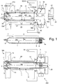
- Fig. 1 shows a first embodiment of a MAS-NMR rotor system 100 according to the invention, comprising a rotor 1, in which a measurement substance is arranged in solid or semi-solid form (such as a powder or gel), and a stator 2.
- a measurement substance is arranged in solid or semi-solid form (such as a powder or gel)
- a stator 2 (together with parts of a stator holder 32), in Fig. 1 Middle of rotor 1 and in Fig. 1
- the entire MAS-NMR rotor system 100 with rotor 1 and stator 2 (together with parts of the stator holder 32) is shown below.
- the MAS-NMR rotor system 100 and the stator holder 32 are part of a probe head arrangement 200 according to the invention.
- the stator 2 comprises a first pneumatic radial bearing 3, a second pneumatic radial bearing 4 and a pneumatic axial bearing 5.
- the rotor 1 is rotatably mounted within the stator 2 about an axis of rotation RA.
- the rotor 1 comprises a circular cylindrical section 6 and an end section 7, which is the in Fig. 1 the left (front), closed end of the rotor 1 forms.
- the end section 7 runs here in the shape of a truncated cone and tapers towards the left-hand end; a cone angle ⁇ of the end section 7 with respect to the axis of rotation RA is approx. 30 ° here; generally 10 ° to 45 ° are preferred.
- an opening 8 is formed which is closed with a cap 9, so that measurement substance filled into the rotor 1 is not lost during an NMR experiment.
- Counter-structures 9a for example baffles (only indicated schematically), through which the rotation of the rotor 1 about the axis of rotation RA can be effected with a suitable gas flow of a pneumatic drive 22, are formed on the cap 9.
- the outer radius R4 of the cap 9 corresponds approximately to the radius R1 of the rotor 1 in the circular cylindrical section 6.
- the circular cylindrical section 6 has the (outer) radius R1 and forms a first bearing surface 10 for the first pneumatic radial bearing 3.
- Stator-side nozzle outlet openings 11 (at the inner end of the nozzle outlet bore) of the first radial bearing 3 are arranged on a radius r1 with respect to the axis of rotation RA.
- the second pneumatic radial bearing 4 has nozzle outlet openings 12 at a radius r2.
- the second radial bearing 4 not only supports the rotor 1 radially in the area of the front end, but can also contribute to holding the rotor 1 axially if the flow conditions are appropriately designed.
- the rotor 1 At the left-hand (front) axial end of the rotor 1, the rotor 1 forms a third bearing surface 14 which, together with a nozzle outlet opening 15, forms the pneumatic axial bearing 5.
- the stator-side parts of the second radial bearing 4 and the axial bearing 5 surround the third bearing surface 14 and here also the rest of the end section 7 in the shape of a cup Radial bearing 4, depending on the design, but also, at least in part, from the first radial bearing 3 and additionally possibly existing temperature control air to the outside. This serves to avoid or minimize a counter pressure which would counteract the holding force of the axial bearing 5.
- the end section 7 extends here over approximately 6.5% of the entire length of the rotor 1 (including the cap 9); generally preferred are 5% to 25%.
- stator-side parts of the second radial bearing 4 and of the pneumatic axial bearing 5 are arranged such that they extend radially approximately as far as the radius R1 of the circular cylindrical section 6.
- r2 ⁇ R1 applies here.
- stator-side parts of the first radial bearing 3 occupy a space beyond R1.
- the stator 2 preferably forms a unitary component, as in FIG Fig. 1 can be seen (but it is also possible to form the stator 2 with parts that are separate from one another).
- the stator 2 has a covering element 16, which has a first bearing base 17, in which the stator-side part of the first radial bearing 3 is formed, and a second bearing base 18, in which the stator-side part of the second radial bearing 4 (and here also the stator-side part of the pneumatic Axial bearing 5) is formed, connects to each other mechanically.
- the enveloping element 16 has a front section 19, which adjoins the second bearing base 18 and has a (largest) outer diameter ADV, and here a rear section 20, with a (largest) outer diameter ADH, which adjoins the first bearing element 17 connects.
- the (largest) outside diameter of the first bearing base 17 is AD1
- the (largest) outside diameter of the second bearing base 18 is AD2.
- the stator 2 of the MAS-NMR rotor system 100 protrudes with the second bearing base 18 and the front section 19 of the casing element 16 through an RF coil arrangement 21 which has a smallest inner diameter IDS.
- the front section 19 has an axial length LV which here is slightly greater than the axial length LS of the HF coil arrangement 21.
- the HF coil arrangement is designed here as a self-supporting wire coil (without a coil carrier).
- the rotor 1 or the substance to be measured can move radially very close to the HF coil arrangement 21.
- AD1> IDS so that the first radial bearing 3 can be designed with a large radius r1 of the nozzle outlet openings 11, and AD1> IDS can also be set up in order to improve the (rear) radial bearing of the rotor 1.
- stator 2 For maintenance purposes it is easily possible to pull the stator 2 axially out of the HF coil arrangement 21 (here to the right) and after a repair (or replacement, if necessary) push it back into the HF coil arrangement 21 (here to the left), without removing the RF coil arrangement 21 from the MAS-NMR probe head arrangement 200.
- a counter bearing 35 can be provided, which pushes the rotor 1 onto the axial bearing 5 at the end here on the cap side, for example with a gas flow through a nozzle outlet opening 36.
- the counter-bearing 35 can be formed in a foldable or displaceable stator part which can be folded away or pushed away for a stator change or can be mounted, for example screwed on, each time the rotor is changed (not shown in detail).
- the counter bearing 35 is integrated into a closure cover 37, with which the stator 2 is closed when the rotor 1 is inserted; the closure cover 37 here also has air outlet openings 34a.
- the stator 2 is mounted in a stator holder 32 which forms a stator bearing 41 for the stator 2, into which the stator 2 can be inserted and removed axially (parallel to the axis of rotation RA); is shown in Fig. 1 above and below the introduced state.
- the stator bearing 41 here comprises a front part 41a which, in the embodiment shown, engages around the second bearing base 18 and forms a radial delimitation 32a for any radial movement of the stator 2.
- the stator bearing 41 here comprises a rear part 41b which, in the embodiments shown, engages around the first bearing base 17 and likewise forms a radial delimitation 32a.
- the rear part 41b also forms an axial stop 32b for the stator 2, against which a shoulder 42 of the first bearing base 17 rests.
- the HF coil arrangement 21 is arranged between the parts 41a, 41b of the stator bearing 41, radially directly adjacent to the casing element 16, and is fastened in a manner not shown in the MAS-NMR probe head arrangement 200, for example on the stator holder 32 (but not on stator 2).
- seals (sealing rings) 30, 31 are arranged, here O-rings elastic material such as rubber. These press here circumferentially on the outer sides of the second bearing base 18 and the first bearing base 17.
- an evacuated space 33 which is also delimited radially on the inside by the enveloping element 16, is sealed.
- the contained HF coil arrangement 21 can be tempered with good thermal insulation, in particular to a cryogenic temperature of, for example, 20 K.
- the seals 31, 30 function in the embodiment of FIG Fig. 1 as stationary (ie immovable in the stator holder 32) securing parts 61, which at the same time have the function of elastic elements 44, which radially brace the inserted stator 2 and thereby fix the stator 2 axially in a frictional connection, insofar as this is necessary in normal operation with regard to the expected forces is required. With greater force, however, the stator 2 can be pulled out axially (here to the right), for example for maintenance, without further mechanisms having to be loosened. It should be noted that when the stator 2 is reinserted into the stator holder 32 at the seals 31, 30, a certain force (mechanical resistance) must be overcome.
- a gas power supply 38 is also connected to the stator 2, here to the first bearing base 17.
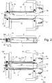
- FIG. 11 shows a second embodiment of a MAS-NMR rotor system 100 according to the invention, which largely corresponds to the embodiment of FIG Fig. 1 so that only the essential differences are shown here.
- the stator 2 (with parts of a stator holder 32) is shown at the top, the rotor 1 in the middle, and the MAS-NMR rotor system 100 with rotor 1 and stator 2 at the bottom.
- the MAS-NMR rotor system 100 and the stator holder 32 are part of a probe head assembly 200 for the invention.
- the rotor 1 has an end section 7 which is designed in the form of a circular cylinder in a front part 7a and is conical (frustoconical) in a rear part 7b, which leads to the circular cylindrical section 6.
- the end section 7 forms the second bearing surface 13 of the second pneumatic radial bearing 4 opposite the nozzle outlet openings 12 in the area of the circular cylindrical front part 7a.
- the radius R2 of the second bearing surface 13 is equal to the radius R3 of the third bearing surface 14 of the pneumatic axial bearing 5, opposite the nozzle outlet opening 15.
- Both R2 and R3 are significantly smaller than the radius R1 of the first bearing surface 10 opposite the nozzle outlet openings 11 of the first radial bearing 3
- Part of the end section 7 is formed here by a cap attachment 39 of the rotor 1.
- Counter-structures 39a for example baffles, are formed on the cap attachment 39 for a drive gas flow of a drive 22 with which the rotor 1 can be set in rotation about the axis of rotation RA.
- the nozzle outlet openings 12 of the second radial bearing 4 are at a radius r2 significantly smaller than the radius r1 of the nozzle outlet openings 11 of the first radial bearing 3, and also significantly smaller than the (outer) radius R1 of the cylindrical section 6, so that here too a very compact design is achievable, which can easily be pushed axially from the side into an RF coil arrangement 21.
- the RF coil arrangement 21 is formed here with a tubular coil carrier 21a, on which the conductor elements 21b of the RF coil arrangement 21 are arranged on the outside.
- the stator 2 has temperature control gas nozzles 51, with which a desired temperature can be set in the stator 2 around the rotor 1, and thus also in the rotor 1.
- the measurement substance can be moderately cooled in the rotor 1 in order to prevent the denaturation of proteins during an NMR measurement, for example at approx. 0 ° C.
- compressed gas nozzles 52 are provided here, with which the pressure on a baffle surface 53 of the rotor 1, formed here on the cap 9, can be adjusted in order to secure the axial position of the rotor 1 during the rotation about the axis of rotation RA.
- an equal or greater gas flow can be used on the second radial bearing 4 than on the first radial bearing 3 in order to achieve approximately the same radial bearing rigidity.
- the second radial bearing 4 can be subjected to a higher pressure than the first radial bearing.
- a counter bearing can also be provided in this embodiment (not shown, but see Fig. 1 and Fig. 3 ).
- a removable securing part 43 is provided which engages behind the stator 2 on the first bearing base 17.
- the detachable securing part 43 is shown in a securing position screwed to the stator holder 32, see the screws 45.
- the securing part 43 presses with elastic elements 44, here springs or alternatively elastomer elements, from behind against the stator 2, causing it to be attached to the stator 2 axial stop 32b is fixed adjacent.
- the stator 2 is therefore elastically braced against the axial stop 32b.
- the screws 45 can be loosened and the securing part 43 (including springs) can be removed.
- the removable securing part 43 also includes a gas power supply 38 here.
- the cladding tube 16 here does not have a rear section that would be further radially than a front section 19, so here the front section 19 (which can be inserted into the RF coil arrangement) extends over the entire length of the cladding tube 16.
- FIG. 3 shows a third embodiment of an inventive MAS-NMR rotor system 100, which largely corresponds to the embodiment of FIG Fig. 1 so that only the essential differences are shown here.
- the stator 2 is again shown, but in a state only partially pushed into the stator holder 32 in the insertion direction ER, with the securing part 50 not yet mounted.
- the rotor 1 is shown in the middle, and the entire MAS-NMR rotor system at the bottom 100 with rotor 1 and stator 2.
- the MAS-NMR rotor system 100 and the stator holder 32 are part of a probe head arrangement 200 for the invention.
- the rotor 1 again has an end section 7 with a circular cylindrical front part 7a and a conical rear part 7b (cf. Fig. 2 ), but without using a cap attachment at the front end.
- the pneumatic drive 22 engages a cap 9 at the rear end of the rotor 1.
- the cladding tube 16 here does not have a rear section which would be further radially than a front section 19, so the front section 19 (which can be inserted into the RF coil arrangement 21) extends here over the entire length of the cladding tube 16.
- the securing part 50 serves to hold the stator 2 in the stator bearing 41 in an axially fully retracted state (with respect to the insertion direction ER or along the axis of rotation RA) (cf. Fig. 3 below, with shoulder 42 and axial stop 32b resting against one another) so that the stator 2 cannot move axially during a measurement.
- the securing part 50 has lugs 50a which can be inserted into grooves 17a on the first bearing base 17.
- the securing part 50 can be screwed to the stator holder 32 by means of screws 45, cf. Fig. 3 below for the screwed-in state.
- the stator 2 is clamped in the radial direction RR.
- a further securing of the stator 2 in the axial direction in the stator bearing 41 is thereby also achieved by frictional connection, beyond the effect of the seals or sealing rings 30, 31.
- the lugs 50a also engage behind the first bearing base 17 in the grooves 17a with respect to the axial direction, as a result of which additional securing occurs.
- the securing part 50 here also contains the gas flow supply 38, the seals 17b sealing off the supply gas flow.
- a counter-bearing 35 is set up in the closure cover 37 in that the outflow of the drive air from the drive 22 is limited, so that a counterpressure is built up which pushes the rotor 1 onto the axial bearing 5.
- an adjustable gas flow limitation device here a variable diaphragm 55, is provided in a gas outlet channel 54.
- Fig. 4 shows, in a schematic sectional view, an embodiment of a probe head arrangement 200 according to the invention, in which an MAS-NMR rotor system 100 according to the invention has been installed, as in FIG Fig. 3 shown.
- the probe head arrangement 200 comprises a stator 2 in which a rotor 1 is mounted rotatably about an axis of rotation RA; the rotor 1 is in Fig. 4 has just been changed and is therefore only partially pushed axially into the stator 2.
- the rear end of the rotor 1 is closed with a cap 9.
- the stator 2 has two bearing bases 17, 18 which are mechanically connected via the casing element 16.
- the probe head arrangement 200 has an RF coil arrangement 21, the smallest inner diameter IDS of the RF coil arrangement 21 being greater than the (largest) outer diameter AD2 of the second bearing base 18 and the (largest) outer diameter ADV in a front section 19 of the enveloping element 16 (which here encompasses the entire length of the enveloping element 16).
- the stator 2 can be guided through the RF coil arrangement 21 during assembly or for maintenance purposes with the fuse component 50 removed.
- the stator 2 In the inserted (pushed in) state, the stator 2 is held in a stator holder 32, which for this purpose forms a stator bearing.
- the bearing is designed in such a way that the axis of rotation RA is aligned at the magic angle of 54.7 ° with respect to a magnetic field B 0 running vertically here.
- the radially outwardly gas-tight stator 2 with gas-tight enveloping element 16 is sealed here in the area of the bearing bases 17, 18 with the seals 30, 31 relative to the stator holder 32, so that the stator 2 or the enveloping element 16 also delimits a space 33; the space 33 is here also delimited by the stator holder 32 and further walls not shown in detail.
- a vacuum is set up here in order to thermally isolate the HF coil arrangement 21.
- a cryogenic temperature for example 77 K, corresponding to liquid nitrogen at normal pressure or, when cooling, for example with liquid or gaseous helium, also lower temperatures, in particular 40 K, 20 K or even in the range around 4.2 K, corresponding to liquid helium at normal pressure
- the measurement substance 40 in the rotor 1 remains at a temperature close to room temperature or at a temperature in the range from -250 ° C to + 1000 ° C, in particular from -50 ° C to + 150 ° C and particularly preferably in a temperature range from 0 ° C to + 50 ° C.
- the rotor 1 rotates in the stator 2 around the axis of rotation RA, typically at a frequency of 10 kHz or more, in particular at speeds in the range from 1 kHz to vs / (2 ⁇ R1), where vs is the speed of sound of the gas surrounding the rotor 1 at present Pressure / temperature conditions is, and the RF coil arrangement 21 radiates RF pulses into the measurement substance 40 in the rotor 1 and / or receives RF signals from the measurement substance 40.
- the strong static magnetic field B 0 acts (with vertical orientation in Fig. 4 ) on the substance 40 to be measured.
- All gas flows are preferably led out at the two ends of the axially removable stator 2 so that it can be easily collected and returned. This is particularly advantageous for low-temperature MAS in order not to lose it into the room air when operating with He gas.
- the gas is preferably transferred directly to a dewar so that it does not heat up unnecessarily and an encapsulated gas circuit becomes possible, which only has to compensate (after-cool) the line losses and the friction in the rotor system 100.
- the after-cooling is preferably carried out with heat exchangers and compression of the gas at room temperature (not shown in detail).
Landscapes
- Physics & Mathematics (AREA)
- Condensed Matter Physics & Semiconductors (AREA)
- General Physics & Mathematics (AREA)
- Spectroscopy & Molecular Physics (AREA)
- High Energy & Nuclear Physics (AREA)
- Magnetic Bearings And Hydrostatic Bearings (AREA)
- Connection Of Motors, Electrical Generators, Mechanical Devices, And The Like (AREA)
Applications Claiming Priority (1)
| Application Number | Priority Date | Filing Date | Title |
|---|---|---|---|
| DE102017220709.4A DE102017220709B4 (de) | 2017-11-20 | 2017-11-20 | MAS-NMR-Rotorsystem mit verbesserter Raumnutzung |
Publications (2)
| Publication Number | Publication Date |
|---|---|
| EP3486670A1 EP3486670A1 (de) | 2019-05-22 |
| EP3486670B1 true EP3486670B1 (de) | 2021-09-01 |
Family
ID=64331783
Family Applications (1)
| Application Number | Title | Priority Date | Filing Date |
|---|---|---|---|
| EP18206513.6A Active EP3486670B1 (de) | 2017-11-20 | 2018-11-15 | Mas-nmr-rotorsystem mit verbesserter raumnutzung |
Country Status (5)
| Country | Link |
|---|---|
| US (1) | US10830845B2 (https=) |
| EP (1) | EP3486670B1 (https=) |
| JP (1) | JP6687708B2 (https=) |
| CN (1) | CN109814052B (https=) |
| DE (1) | DE102017220709B4 (https=) |
Families Citing this family (3)
| Publication number | Priority date | Publication date | Assignee | Title |
|---|---|---|---|---|
| DE102017220709B4 (de) * | 2017-11-20 | 2019-05-29 | Bruker Biospin Ag | MAS-NMR-Rotorsystem mit verbesserter Raumnutzung |
| CN117169795B (zh) * | 2023-11-02 | 2024-02-27 | 中国科学院精密测量科学与技术创新研究院 | 一种多通道分布式原位在场固体核磁共振加热装置及方法 |
| CN120824094B (zh) * | 2025-09-19 | 2026-02-03 | 岩超聚能(上海)科技有限公司 | 仿星器磁体 |
Family Cites Families (49)
| Publication number | Priority date | Publication date | Assignee | Title |
|---|---|---|---|---|
| US4275350A (en) | 1979-05-29 | 1981-06-23 | Varian Associates, Inc. | Sample spinning mechanism for NMR probes |
| US4446430A (en) * | 1981-08-31 | 1984-05-01 | Monsanto Company | Sample spinner for nuclear magnetic resonance spectrometer |
| US4456882A (en) * | 1982-01-04 | 1984-06-26 | University Of South Carolina | High speed cylindrical nuclear magnetic resonance (NMR) sample spinner |
| US4511841A (en) * | 1982-06-17 | 1985-04-16 | Chemagnetics, Inc. | Method and apparatus for high speed magic angle spinning |
| JPS6136613A (ja) | 1984-07-26 | 1986-02-21 | Babcock Hitachi Kk | ス−トブロワ制御装置 |
| US4739270A (en) | 1986-06-03 | 1988-04-19 | Varian Associates, Inc. | High speed spinner for NMR spectrometer |
| US4806868A (en) | 1987-11-13 | 1989-02-21 | Varian Associates, Inc. | NMR spinner speed control |
| US4940942A (en) * | 1989-04-14 | 1990-07-10 | Bartuska Victor J | Method and apparatus for conducting variable-temperature solid state magnetic resonance spectroscopy |
| US5202633A (en) * | 1990-11-01 | 1993-04-13 | Doty Scientific, Inc. | High temperature nmr sample spinner |
| US5508615A (en) | 1991-02-25 | 1996-04-16 | Doty; F. David | Supersonic sample spinner |
| US5325059A (en) | 1992-03-26 | 1994-06-28 | Doty Scientific Inc. | DOR NMR sample spinner |
| US5289130A (en) * | 1992-07-31 | 1994-02-22 | Doty Scientific Inc. | NMR sample rotor cooling technique |
| JPH0814618A (ja) | 1994-06-27 | 1996-01-19 | Matsushita Seiko Co Ltd | レンジフード |
| JP3817747B2 (ja) | 1994-08-31 | 2006-09-06 | カシオ計算機株式会社 | 書体情報設定装置 |
| DE4442742C1 (de) * | 1994-12-01 | 1996-05-23 | Bruker Analytische Messtechnik | Probenkopf für die Kernresonanz-Spektroskopie |
| US5644235A (en) * | 1995-06-07 | 1997-07-01 | Varian Associates, Inc. | Use of audio signals for monitoring sample spinning speeds in nuclear magnetic spectrometers |
| AU725539B2 (en) * | 1996-12-23 | 2000-10-12 | Doty Scientific, Inc. | Thermal buffering of cross-coils in high-power NMR decoupling |
| US6054857A (en) | 1997-03-18 | 2000-04-25 | Doty Scientific, Inc. | NMR MAS sealing sample cells and methods |
| AU6564098A (en) * | 1997-03-20 | 1998-10-12 | F. David Doty | Hr mas nmr coils with magic angle capacitors |
| US6653832B2 (en) | 2001-03-09 | 2003-11-25 | Battelle Memorial Institute | Method for high resolution magnetic resonance analysis using magic angle technique |
| JP2003177172A (ja) | 2001-10-03 | 2003-06-27 | Jeol Ltd | 固体nmr測定用高速スピナー |
| US7081753B2 (en) * | 2004-07-26 | 2006-07-25 | Varian, Inc. | Multiple tuned scroll coil |
| US7170292B2 (en) * | 2004-10-20 | 2007-01-30 | Doty Scientific, Inc. | NMR MAS inflow bernoulli bearing |
| WO2006085261A2 (en) * | 2005-02-10 | 2006-08-17 | Doty Scientific, Inc. | Nmr cryomas probe for high-field wide-bore magnets |
| US7196521B2 (en) | 2005-03-29 | 2007-03-27 | Doty Scientific, Inc. | NMR MAS electret spin rate detection |
| DE102005039087B3 (de) * | 2005-08-04 | 2007-03-29 | Bruker Biospin Gmbh | Probenkopf für Kernresonanzmessungen |
| WO2008070430A1 (en) * | 2006-12-08 | 2008-06-12 | Doty Scientific, Inc. | Improved nmr cryomas probe for high-field wide-bore magnets |
| US7541807B2 (en) | 2007-07-19 | 2009-06-02 | Varian, Inc. | Rotor drive apparatus and methods utilizing center-fed radial-outflow gas |
| US8212565B2 (en) * | 2009-10-29 | 2012-07-03 | Bruker Biospin Corporation | NMR MAS rotor assembly with porous ceramic bearings |
| WO2012035162A2 (en) * | 2010-09-16 | 2012-03-22 | Ago Samoson | Nmr probeheads and methods with multi-functional sample rotation |
| JP6019515B2 (ja) * | 2012-05-15 | 2016-11-02 | 日本電子株式会社 | Nmr用試料管およびnmr装置 |
| US9062904B2 (en) * | 2012-10-23 | 2015-06-23 | Doty Scientific, Inc. | Stabilizing control of a saturated cold gas stream |
| US9366736B2 (en) * | 2012-12-13 | 2016-06-14 | Battelle Memorial Institute | Sealed magic angle spinning nuclear magnetic resonance probe and process for spectroscopy of hazardous samples |
| DE102013201110B3 (de) * | 2013-01-24 | 2014-04-10 | Bruker Biospin Gmbh | NMR-MAS-Probenkopf mit integrierter Transportleitung für einen MAS-Rotor |
| CN103176153B (zh) | 2013-03-05 | 2015-08-26 | 杨晓冬 | 高分辨率核磁共振分析装置 |
| WO2014194408A1 (en) | 2013-06-03 | 2014-12-11 | Nanalysis Corp. | Magnet assemblies |
| DE102013215782B4 (de) * | 2013-08-09 | 2018-09-27 | Bruker Biospin Gmbh | Mikrowellenkoppler zur Optimierung eines NMR-Probenkopfes für MAS-DNP |
| DE102014201076B3 (de) * | 2014-01-22 | 2015-03-05 | Bruker Biospin Ag | Transportbehälter für einen NMR MAS-Rotor |
| DE102015208850B4 (de) * | 2015-05-13 | 2018-12-20 | Bruker Biospin Gmbh | MAS-Stator mit Absaugvorrichtung |
| DE202015105448U1 (de) | 2015-10-14 | 2017-01-17 | Bruker Biospin Gmbh | Turbinenkappe, zugehöriger NMR-MAS-Rotor und zugehöriger NMR-MAS-Stator, insbesondere mit einem 0,7 mm Rotor-Röhrchen |
| DE102015222935B3 (de) * | 2015-11-20 | 2017-03-09 | Bruker Biospin Ag | Winkelverstellbarer Messkopf einer NMR-MAS-Apparatur |
| FR3046678B1 (fr) * | 2016-01-12 | 2018-02-16 | Commissariat A L'energie Atomique Et Aux Energies Alternatives | Systeme de canalisation de fluide d'un systeme rmn et procede de fonctionnement d'un tel systeme. |
| DE102016202943B3 (de) | 2016-02-25 | 2017-05-18 | Bruker Biospin Ag | Messkopf einer NMR-MAS-Apparatur mit Vorrichtung zur Bestimmung des Winkels zwischen MAS-Rotor und statischem Magnetfeld |
| DE102016207998B3 (de) * | 2016-05-10 | 2017-09-21 | Bruker Biospin Gmbh | MAS-Stator eines NMR-Probenkopfes mit optimierter Mikrowelleneinstrahlung |
| DE102016212018A1 (de) * | 2016-07-01 | 2018-01-04 | Bruker Biospin Ag | HF-Spulenanordnung |
| DE102016218772A1 (de) * | 2016-09-28 | 2018-03-29 | Bruker Biospin Gmbh | Verbesserte Temperierung eines NMR-MAS-Rotors |
| DE102017220709B4 (de) * | 2017-11-20 | 2019-05-29 | Bruker Biospin Ag | MAS-NMR-Rotorsystem mit verbesserter Raumnutzung |
| DE102017220707B4 (de) * | 2017-11-20 | 2019-05-29 | Bruker Biospin Ag | MAS-NMR-Probenkopfanordnung mit auswechselbarem Stator |
| DE102018204913B3 (de) * | 2018-03-29 | 2019-03-07 | Bruker Biospin Gmbh | NMR-MAS-Probenkopf mit optimiertem MAS-DNP-Spulenklotz für schnelle Probenrotation |
-
2017
- 2017-11-20 DE DE102017220709.4A patent/DE102017220709B4/de not_active Expired - Fee Related
-
2018
- 2018-11-15 EP EP18206513.6A patent/EP3486670B1/de active Active
- 2018-11-16 JP JP2018215648A patent/JP6687708B2/ja active Active
- 2018-11-19 US US16/194,907 patent/US10830845B2/en active Active
- 2018-11-20 CN CN201811379550.3A patent/CN109814052B/zh active Active
Also Published As
| Publication number | Publication date |
|---|---|
| CN109814052A (zh) | 2019-05-28 |
| CN109814052B (zh) | 2020-06-16 |
| JP6687708B2 (ja) | 2020-04-28 |
| US10830845B2 (en) | 2020-11-10 |
| DE102017220709B4 (de) | 2019-05-29 |
| JP2019109227A (ja) | 2019-07-04 |
| DE102017220709A1 (de) | 2019-05-23 |
| US20190154771A1 (en) | 2019-05-23 |
| EP3486670A1 (de) | 2019-05-22 |
Similar Documents
| Publication | Publication Date | Title |
|---|---|---|
| EP3486670B1 (de) | Mas-nmr-rotorsystem mit verbesserter raumnutzung | |
| EP2388609B1 (de) | Temperiereinrichtung für ein NMR-Probenröhrchen | |
| DE102008054152B3 (de) | NMR-MAS-Probenkopf mit integrierter Transportleitung für einen MAS-Rotor | |
| DE102013201110B3 (de) | NMR-MAS-Probenkopf mit integrierter Transportleitung für einen MAS-Rotor | |
| EP3301467B1 (de) | Verbesserte temperierung eines nmr-mas-rotors | |
| DE3839046C2 (https=) | ||
| EP3093679B1 (de) | Mas-stator mit absaugvorrichtung | |
| EP3171191B1 (de) | Winkelverstellbarer messkopf einer nmr-mas-apparatur | |
| EP3696559B1 (de) | Mas-probenkopf mit thermisch isolierter probenkammer | |
| EP3486671B1 (de) | Mas-nmr-probenkopfanordnung mit auswechselbarem stator | |
| EP1126269B1 (de) | Vorrichtung zur dynamischen mechanischen Analyse von Proben | |
| DE102005039087B3 (de) | Probenkopf für Kernresonanzmessungen | |
| EP3881088B1 (de) | Temperierung für ein nmr-probenröhrchen | |
| WO2012052261A2 (de) | Supraleitende elektrische maschine mit einer verbindungseinrichtung zum axialen dehnungsausgleich eines wicklungsträgers | |
| EP3889630B1 (de) | Magnetisch-kompensierter nmr-rotor und verfahren zur auslegung und herstellung | |
| EP3953724B1 (de) | Nmr-messanordnung mit kalter bohrung des kryostaten | |
| EP1681576B1 (de) | Kryostatanordnung | |
| DE3332739A1 (de) | Immersions-kryofixation mit nachfolgender rotation des objekts | |
| EP3543680B1 (de) | Vorrichtung und verfahren zur thermischen lagerung von proben | |
| DE102023202880B3 (de) | Verwendung Funktionsspezifischer Gase in einer MAS-Mikrogasturbine für die Festkörper NMR | |
| DE102025109424B3 (de) | NMR-Probenkopf mit Temperiervorrichtung aus thermisch gut leitfähigem Material | |
| DE1900434B2 (de) | Temperaturwechselpruefgeraet zur untersuchung von kernbrennstoffelementen | |
| EP1970920A1 (de) | Horizontale Magnetanordnung mit radialem Zugang | |
| DE4039332A1 (de) | Nmr-magnetsystem mit supraleitender spule in einem unterkuehlten heliumbad auf atmosphaerendruck | |
| DD267328A1 (de) | Anordnung zum einsatz von glasampullen als probenbehaelter fuer die schnelle probenrotation in der kernmagnetischen resonanz |
Legal Events
| Date | Code | Title | Description |
|---|---|---|---|
| PUAI | Public reference made under article 153(3) epc to a published international application that has entered the european phase |
Free format text: ORIGINAL CODE: 0009012 |
|
| STAA | Information on the status of an ep patent application or granted ep patent |
Free format text: STATUS: THE APPLICATION HAS BEEN PUBLISHED |
|
| AK | Designated contracting states |
Kind code of ref document: A1 Designated state(s): AL AT BE BG CH CY CZ DE DK EE ES FI FR GB GR HR HU IE IS IT LI LT LU LV MC MK MT NL NO PL PT RO RS SE SI SK SM TR |
|
| AX | Request for extension of the european patent |
Extension state: BA ME |
|
| RAP1 | Party data changed (applicant data changed or rights of an application transferred) |
Owner name: BRUKER SWITZERLAND AG |
|
| STAA | Information on the status of an ep patent application or granted ep patent |
Free format text: STATUS: REQUEST FOR EXAMINATION WAS MADE |
|
| 17P | Request for examination filed |
Effective date: 20191122 |
|
| RBV | Designated contracting states (corrected) |
Designated state(s): AL AT BE BG CH CY CZ DE DK EE ES FI FR GB GR HR HU IE IS IT LI LT LU LV MC MK MT NL NO PL PT RO RS SE SI SK SM TR |
|
| RIC1 | Information provided on ipc code assigned before grant |
Ipc: G01R 33/30 20060101AFI20210311BHEP |
|
| GRAP | Despatch of communication of intention to grant a patent |
Free format text: ORIGINAL CODE: EPIDOSNIGR1 |
|
| STAA | Information on the status of an ep patent application or granted ep patent |
Free format text: STATUS: GRANT OF PATENT IS INTENDED |
|
| INTG | Intention to grant announced |
Effective date: 20210517 |
|
| GRAS | Grant fee paid |
Free format text: ORIGINAL CODE: EPIDOSNIGR3 |
|
| GRAA | (expected) grant |
Free format text: ORIGINAL CODE: 0009210 |
|
| STAA | Information on the status of an ep patent application or granted ep patent |
Free format text: STATUS: THE PATENT HAS BEEN GRANTED |
|
| AK | Designated contracting states |
Kind code of ref document: B1 Designated state(s): AL AT BE BG CH CY CZ DE DK EE ES FI FR GB GR HR HU IE IS IT LI LT LU LV MC MK MT NL NO PL PT RO RS SE SI SK SM TR |
|
| REG | Reference to a national code |
Ref country code: GB Ref legal event code: FG4D Free format text: NOT ENGLISH |
|
| REG | Reference to a national code |
Ref country code: CH Ref legal event code: EP Ref country code: AT Ref legal event code: REF Ref document number: 1426779 Country of ref document: AT Kind code of ref document: T Effective date: 20210915 |
|
| REG | Reference to a national code |
Ref country code: DE Ref legal event code: R096 Ref document number: 502018006810 Country of ref document: DE |
|
| REG | Reference to a national code |
Ref country code: IE Ref legal event code: FG4D Free format text: LANGUAGE OF EP DOCUMENT: GERMAN |
|
| REG | Reference to a national code |
Ref country code: LT Ref legal event code: MG9D |
|
| REG | Reference to a national code |
Ref country code: NL Ref legal event code: MP Effective date: 20210901 |
|
| PG25 | Lapsed in a contracting state [announced via postgrant information from national office to epo] |
Ref country code: HR Free format text: LAPSE BECAUSE OF FAILURE TO SUBMIT A TRANSLATION OF THE DESCRIPTION OR TO PAY THE FEE WITHIN THE PRESCRIBED TIME-LIMIT Effective date: 20210901 Ref country code: ES Free format text: LAPSE BECAUSE OF FAILURE TO SUBMIT A TRANSLATION OF THE DESCRIPTION OR TO PAY THE FEE WITHIN THE PRESCRIBED TIME-LIMIT Effective date: 20210901 Ref country code: FI Free format text: LAPSE BECAUSE OF FAILURE TO SUBMIT A TRANSLATION OF THE DESCRIPTION OR TO PAY THE FEE WITHIN THE PRESCRIBED TIME-LIMIT Effective date: 20210901 Ref country code: RS Free format text: LAPSE BECAUSE OF FAILURE TO SUBMIT A TRANSLATION OF THE DESCRIPTION OR TO PAY THE FEE WITHIN THE PRESCRIBED TIME-LIMIT Effective date: 20210901 Ref country code: SE Free format text: LAPSE BECAUSE OF FAILURE TO SUBMIT A TRANSLATION OF THE DESCRIPTION OR TO PAY THE FEE WITHIN THE PRESCRIBED TIME-LIMIT Effective date: 20210901 Ref country code: NO Free format text: LAPSE BECAUSE OF FAILURE TO SUBMIT A TRANSLATION OF THE DESCRIPTION OR TO PAY THE FEE WITHIN THE PRESCRIBED TIME-LIMIT Effective date: 20211201 Ref country code: BG Free format text: LAPSE BECAUSE OF FAILURE TO SUBMIT A TRANSLATION OF THE DESCRIPTION OR TO PAY THE FEE WITHIN THE PRESCRIBED TIME-LIMIT Effective date: 20211201 Ref country code: LT Free format text: LAPSE BECAUSE OF FAILURE TO SUBMIT A TRANSLATION OF THE DESCRIPTION OR TO PAY THE FEE WITHIN THE PRESCRIBED TIME-LIMIT Effective date: 20210901 |
|
| PG25 | Lapsed in a contracting state [announced via postgrant information from national office to epo] |
Ref country code: PL Free format text: LAPSE BECAUSE OF FAILURE TO SUBMIT A TRANSLATION OF THE DESCRIPTION OR TO PAY THE FEE WITHIN THE PRESCRIBED TIME-LIMIT Effective date: 20210901 Ref country code: LV Free format text: LAPSE BECAUSE OF FAILURE TO SUBMIT A TRANSLATION OF THE DESCRIPTION OR TO PAY THE FEE WITHIN THE PRESCRIBED TIME-LIMIT Effective date: 20210901 Ref country code: GR Free format text: LAPSE BECAUSE OF FAILURE TO SUBMIT A TRANSLATION OF THE DESCRIPTION OR TO PAY THE FEE WITHIN THE PRESCRIBED TIME-LIMIT Effective date: 20211202 |
|
| PG25 | Lapsed in a contracting state [announced via postgrant information from national office to epo] |
Ref country code: IS Free format text: LAPSE BECAUSE OF FAILURE TO SUBMIT A TRANSLATION OF THE DESCRIPTION OR TO PAY THE FEE WITHIN THE PRESCRIBED TIME-LIMIT Effective date: 20220101 Ref country code: SM Free format text: LAPSE BECAUSE OF FAILURE TO SUBMIT A TRANSLATION OF THE DESCRIPTION OR TO PAY THE FEE WITHIN THE PRESCRIBED TIME-LIMIT Effective date: 20210901 Ref country code: SK Free format text: LAPSE BECAUSE OF FAILURE TO SUBMIT A TRANSLATION OF THE DESCRIPTION OR TO PAY THE FEE WITHIN THE PRESCRIBED TIME-LIMIT Effective date: 20210901 Ref country code: RO Free format text: LAPSE BECAUSE OF FAILURE TO SUBMIT A TRANSLATION OF THE DESCRIPTION OR TO PAY THE FEE WITHIN THE PRESCRIBED TIME-LIMIT Effective date: 20210901 Ref country code: PT Free format text: LAPSE BECAUSE OF FAILURE TO SUBMIT A TRANSLATION OF THE DESCRIPTION OR TO PAY THE FEE WITHIN THE PRESCRIBED TIME-LIMIT Effective date: 20220103 Ref country code: NL Free format text: LAPSE BECAUSE OF FAILURE TO SUBMIT A TRANSLATION OF THE DESCRIPTION OR TO PAY THE FEE WITHIN THE PRESCRIBED TIME-LIMIT Effective date: 20210901 Ref country code: EE Free format text: LAPSE BECAUSE OF FAILURE TO SUBMIT A TRANSLATION OF THE DESCRIPTION OR TO PAY THE FEE WITHIN THE PRESCRIBED TIME-LIMIT Effective date: 20210901 Ref country code: CZ Free format text: LAPSE BECAUSE OF FAILURE TO SUBMIT A TRANSLATION OF THE DESCRIPTION OR TO PAY THE FEE WITHIN THE PRESCRIBED TIME-LIMIT Effective date: 20210901 Ref country code: AL Free format text: LAPSE BECAUSE OF FAILURE TO SUBMIT A TRANSLATION OF THE DESCRIPTION OR TO PAY THE FEE WITHIN THE PRESCRIBED TIME-LIMIT Effective date: 20210901 |
|
| REG | Reference to a national code |
Ref country code: DE Ref legal event code: R097 Ref document number: 502018006810 Country of ref document: DE |
|
| PG25 | Lapsed in a contracting state [announced via postgrant information from national office to epo] |
Ref country code: MC Free format text: LAPSE BECAUSE OF FAILURE TO SUBMIT A TRANSLATION OF THE DESCRIPTION OR TO PAY THE FEE WITHIN THE PRESCRIBED TIME-LIMIT Effective date: 20210901 |
|
| PLBE | No opposition filed within time limit |
Free format text: ORIGINAL CODE: 0009261 |
|
| STAA | Information on the status of an ep patent application or granted ep patent |
Free format text: STATUS: NO OPPOSITION FILED WITHIN TIME LIMIT |
|
| PG25 | Lapsed in a contracting state [announced via postgrant information from national office to epo] |
Ref country code: LU Free format text: LAPSE BECAUSE OF NON-PAYMENT OF DUE FEES Effective date: 20211115 Ref country code: IT Free format text: LAPSE BECAUSE OF FAILURE TO SUBMIT A TRANSLATION OF THE DESCRIPTION OR TO PAY THE FEE WITHIN THE PRESCRIBED TIME-LIMIT Effective date: 20210901 Ref country code: DK Free format text: LAPSE BECAUSE OF FAILURE TO SUBMIT A TRANSLATION OF THE DESCRIPTION OR TO PAY THE FEE WITHIN THE PRESCRIBED TIME-LIMIT Effective date: 20210901 Ref country code: BE Free format text: LAPSE BECAUSE OF NON-PAYMENT OF DUE FEES Effective date: 20211130 |
|
| REG | Reference to a national code |
Ref country code: BE Ref legal event code: MM Effective date: 20211130 |
|
| 26N | No opposition filed |
Effective date: 20220602 |
|
| PG25 | Lapsed in a contracting state [announced via postgrant information from national office to epo] |
Ref country code: SI Free format text: LAPSE BECAUSE OF FAILURE TO SUBMIT A TRANSLATION OF THE DESCRIPTION OR TO PAY THE FEE WITHIN THE PRESCRIBED TIME-LIMIT Effective date: 20210901 |
|
| PG25 | Lapsed in a contracting state [announced via postgrant information from national office to epo] |
Ref country code: IE Free format text: LAPSE BECAUSE OF NON-PAYMENT OF DUE FEES Effective date: 20211115 |
|
| PG25 | Lapsed in a contracting state [announced via postgrant information from national office to epo] |
Ref country code: CY Free format text: LAPSE BECAUSE OF FAILURE TO SUBMIT A TRANSLATION OF THE DESCRIPTION OR TO PAY THE FEE WITHIN THE PRESCRIBED TIME-LIMIT Effective date: 20210901 |
|
| PG25 | Lapsed in a contracting state [announced via postgrant information from national office to epo] |
Ref country code: HU Free format text: LAPSE BECAUSE OF FAILURE TO SUBMIT A TRANSLATION OF THE DESCRIPTION OR TO PAY THE FEE WITHIN THE PRESCRIBED TIME-LIMIT; INVALID AB INITIO Effective date: 20181115 |
|
| P01 | Opt-out of the competence of the unified patent court (upc) registered |
Effective date: 20231221 |
|
| PG25 | Lapsed in a contracting state [announced via postgrant information from national office to epo] |
Ref country code: MK Free format text: LAPSE BECAUSE OF FAILURE TO SUBMIT A TRANSLATION OF THE DESCRIPTION OR TO PAY THE FEE WITHIN THE PRESCRIBED TIME-LIMIT Effective date: 20210901 |
|
| PG25 | Lapsed in a contracting state [announced via postgrant information from national office to epo] |
Ref country code: MT Free format text: LAPSE BECAUSE OF FAILURE TO SUBMIT A TRANSLATION OF THE DESCRIPTION OR TO PAY THE FEE WITHIN THE PRESCRIBED TIME-LIMIT Effective date: 20210901 |
|
| REG | Reference to a national code |
Ref country code: AT Ref legal event code: MM01 Ref document number: 1426779 Country of ref document: AT Kind code of ref document: T Effective date: 20231115 |
|
| PG25 | Lapsed in a contracting state [announced via postgrant information from national office to epo] |
Ref country code: AT Free format text: LAPSE BECAUSE OF NON-PAYMENT OF DUE FEES Effective date: 20231115 |
|
| PG25 | Lapsed in a contracting state [announced via postgrant information from national office to epo] |
Ref country code: AT Free format text: LAPSE BECAUSE OF NON-PAYMENT OF DUE FEES Effective date: 20231115 |
|
| REG | Reference to a national code |
Ref country code: CH Ref legal event code: U11 Free format text: ST27 STATUS EVENT CODE: U-0-0-U10-U11 (AS PROVIDED BY THE NATIONAL OFFICE) Effective date: 20251201 |
|
| PG25 | Lapsed in a contracting state [announced via postgrant information from national office to epo] |
Ref country code: TR Free format text: LAPSE BECAUSE OF FAILURE TO SUBMIT A TRANSLATION OF THE DESCRIPTION OR TO PAY THE FEE WITHIN THE PRESCRIBED TIME-LIMIT Effective date: 20210901 |
|
| PGFP | Annual fee paid to national office [announced via postgrant information from national office to epo] |
Ref country code: DE Payment date: 20251118 Year of fee payment: 8 |
|
| PGFP | Annual fee paid to national office [announced via postgrant information from national office to epo] |
Ref country code: GB Payment date: 20251120 Year of fee payment: 8 |
|
| PGFP | Annual fee paid to national office [announced via postgrant information from national office to epo] |
Ref country code: FR Payment date: 20251120 Year of fee payment: 8 |
|
| PGFP | Annual fee paid to national office [announced via postgrant information from national office to epo] |
Ref country code: CH Payment date: 20251201 Year of fee payment: 8 |
|
| PGFP | Annual fee paid to national office [announced via postgrant information from national office to epo] |
Ref country code: AT Payment date: 20260410 Year of fee payment: 5 |