EP3486670B1 - Mas-nmr rotor system with improved space utilization - Google Patents
Mas-nmr rotor system with improved space utilization Download PDFInfo
- Publication number
- EP3486670B1 EP3486670B1 EP18206513.6A EP18206513A EP3486670B1 EP 3486670 B1 EP3486670 B1 EP 3486670B1 EP 18206513 A EP18206513 A EP 18206513A EP 3486670 B1 EP3486670 B1 EP 3486670B1
- Authority
- EP
- European Patent Office
- Prior art keywords
- rotor
- stator
- bearing
- radius
- rotor system
- Prior art date
- Legal status (The legal status is an assumption and is not a legal conclusion. Google has not performed a legal analysis and makes no representation as to the accuracy of the status listed.)
- Active
Links
- 239000000126 substance Substances 0.000 claims description 42
- 239000000523 sample Substances 0.000 claims description 34
- 238000005004 MAS NMR spectroscopy Methods 0.000 claims description 32
- 238000005259 measurement Methods 0.000 claims description 27
- 230000007423 decrease Effects 0.000 claims description 2
- 238000002474 experimental method Methods 0.000 claims description 2
- 230000001678 irradiating effect Effects 0.000 claims 1
- 239000007789 gas Substances 0.000 description 38
- 238000009413 insulation Methods 0.000 description 10
- 238000005481 NMR spectroscopy Methods 0.000 description 6
- 238000013461 design Methods 0.000 description 6
- 238000011161 development Methods 0.000 description 5
- 230000018109 developmental process Effects 0.000 description 5
- 238000003860 storage Methods 0.000 description 5
- 238000005253 cladding Methods 0.000 description 4
- 238000001816 cooling Methods 0.000 description 4
- 238000003780 insertion Methods 0.000 description 4
- 230000037431 insertion Effects 0.000 description 4
- 238000012423 maintenance Methods 0.000 description 4
- 238000007789 sealing Methods 0.000 description 4
- 239000007787 solid Substances 0.000 description 4
- IJGRMHOSHXDMSA-UHFFFAOYSA-N Atomic nitrogen Chemical compound N#N IJGRMHOSHXDMSA-UHFFFAOYSA-N 0.000 description 3
- 238000010276 construction Methods 0.000 description 3
- 239000001307 helium Substances 0.000 description 3
- 229910052734 helium Inorganic materials 0.000 description 3
- SWQJXJOGLNCZEY-UHFFFAOYSA-N helium atom Chemical compound [He] SWQJXJOGLNCZEY-UHFFFAOYSA-N 0.000 description 3
- 230000003993 interaction Effects 0.000 description 3
- 239000007788 liquid Substances 0.000 description 3
- 230000003068 static effect Effects 0.000 description 3
- 230000007704 transition Effects 0.000 description 3
- 238000012565 NMR experiment Methods 0.000 description 2
- 230000004323 axial length Effects 0.000 description 2
- 229920001971 elastomer Polymers 0.000 description 2
- 239000000203 mixture Substances 0.000 description 2
- 238000000655 nuclear magnetic resonance spectrum Methods 0.000 description 2
- 230000009467 reduction Effects 0.000 description 2
- 240000003517 Elaeocarpus dentatus Species 0.000 description 1
- 238000004458 analytical method Methods 0.000 description 1
- 230000015572 biosynthetic process Effects 0.000 description 1
- 238000007664 blowing Methods 0.000 description 1
- 230000000711 cancerogenic effect Effects 0.000 description 1
- 231100000315 carcinogenic Toxicity 0.000 description 1
- 230000008859 change Effects 0.000 description 1
- 239000003638 chemical reducing agent Substances 0.000 description 1
- 230000006835 compression Effects 0.000 description 1
- 238000007906 compression Methods 0.000 description 1
- 239000004020 conductor Substances 0.000 description 1
- 238000004925 denaturation Methods 0.000 description 1
- 230000036425 denaturation Effects 0.000 description 1
- 238000001514 detection method Methods 0.000 description 1
- 229910001873 dinitrogen Inorganic materials 0.000 description 1
- 230000000694 effects Effects 0.000 description 1
- 239000013013 elastic material Substances 0.000 description 1
- 239000000806 elastomer Substances 0.000 description 1
- 239000002360 explosive Substances 0.000 description 1
- 238000007667 floating Methods 0.000 description 1
- 239000003550 marker Substances 0.000 description 1
- 230000007246 mechanism Effects 0.000 description 1
- 238000000034 method Methods 0.000 description 1
- 229910052757 nitrogen Inorganic materials 0.000 description 1
- 210000001331 nose Anatomy 0.000 description 1
- 238000005192 partition Methods 0.000 description 1
- 239000011148 porous material Substances 0.000 description 1
- 239000000843 powder Substances 0.000 description 1
- 238000003825 pressing Methods 0.000 description 1
- 102000004169 proteins and genes Human genes 0.000 description 1
- 108090000623 proteins and genes Proteins 0.000 description 1
- 230000002285 radioactive effect Effects 0.000 description 1
- 230000008439 repair process Effects 0.000 description 1
- 230000000284 resting effect Effects 0.000 description 1
- 238000004904 shortening Methods 0.000 description 1
- 238000004611 spectroscopical analysis Methods 0.000 description 1
- 238000009987 spinning Methods 0.000 description 1
- 231100000331 toxic Toxicity 0.000 description 1
- 230000002588 toxic effect Effects 0.000 description 1
- 238000012546 transfer Methods 0.000 description 1
Images


Classifications
-
- G—PHYSICS
- G01—MEASURING; TESTING
- G01R—MEASURING ELECTRIC VARIABLES; MEASURING MAGNETIC VARIABLES
- G01R33/00—Arrangements or instruments for measuring magnetic variables
- G01R33/20—Arrangements or instruments for measuring magnetic variables involving magnetic resonance
- G01R33/28—Details of apparatus provided for in groups G01R33/44 - G01R33/64
- G01R33/30—Sample handling arrangements, e.g. sample cells, spinning mechanisms
- G01R33/307—Sample handling arrangements, e.g. sample cells, spinning mechanisms specially adapted for moving the sample relative to the MR system, e.g. spinning mechanisms, flow cells or means for positioning the sample inside a spectrometer
-
- G—PHYSICS
- G01—MEASURING; TESTING
- G01R—MEASURING ELECTRIC VARIABLES; MEASURING MAGNETIC VARIABLES
- G01R33/00—Arrangements or instruments for measuring magnetic variables
- G01R33/20—Arrangements or instruments for measuring magnetic variables involving magnetic resonance
- G01R33/44—Arrangements or instruments for measuring magnetic variables involving magnetic resonance using nuclear magnetic resonance [NMR]
- G01R33/46—NMR spectroscopy
Definitions
- Such a rotor system is, for example, from US 2016/0334478 A1 known.
- the substance to be measured is exposed to a strong, static magnetic field, which leads to the alignment of nuclear spins in the substance to be measured.
- HF high frequency
- the substance to be measured is typically filled into an essentially cylindrical sample tube, called a rotor, and placed in a stator.
- the rotor is set in rotation relative to the stator, the rotor floating in the stator; suitable gas flows are used for this.
- an RF coil arrangement is provided which surrounds the stator.
- the rotor and the RF coil arrangement are in the same environment at room temperature.
- the RF coil arrangement can be cooled.
- the HF coil arrangement should be provided with insulation, for example vacuum insulation.
- Such an insulation increases the radial distance between the rotor or the measuring substance and the HF coil arrangement, i.e. the HF coil arrangement must be selected with a larger diameter, of which only a smaller proportion is filled with sample substance.
- the HF coil arrangement must be axially isolated from the stator, which in the case of radially expanded radial bearing parts on the stator side leads to a shortening of the coil length and thus a reduction in the measurement volume with the same measurement sample volume.
- the performance losses due to the geometric disadvantages would largely cancel out or even exceed the gain that can be achieved by reducing the noise due to the lowered temperature of the RF coil arrangement.
- such an insulation is very difficult to retrofit in a MAS-NMR probe head.
- a rotor system with two radial bearings of the same radii and a conical bottom bearing that is blown at an angle is from the U.S. 7,196,521 known.
- From the U.S. 4,275,350 and the U.S. 4,806,868 are rotor systems with a radial bearing and a conical drive known.
- the U.S. 4,739,270 describes a rotor system with two radial bearings of the same radii, and with a narrowing at the end as a marker for spinning detection.
- 5,508,615 show rotor systems, the rotor having end-side constrictions on which a drive acts; it is supported by two radial bearings on the same, large diameter.
- the rotor In the U.S. 6,054,857 there is a drive via narrowed end caps.
- the rotor In the U.S. 6,803,764 the rotor has a constriction at one end, on which the drive acts; the bearing is carried out by means of two radial bearings on the same, large diameter and by means of a floor bearing.
- NMR-MAS probe head has become known in which a rotor is held with two radial bearings that are designed with the same radius. Cold helium gas flows through a chamber between the radial bearings, in which a central part of the rotor and an RF coil are arranged; Nitrogen gas is used to drive the rotor on a rotor tip and on the radial bearings.
- the invention is based on the object of providing a MAS-NMR rotor system with which an RF coil arrangement can move radially particularly close to a measurement substance in the rotor and the MAS-NMR rotor system can easily move into and out of the RF coil arrangement is executable.
- a rotor system of the type mentioned at the beginning which thereby is characterized in that the second radial bearing is formed at an end portion of the rotor which has a smaller radius than the circular cylindrical portion or which decreases away from the circular cylindrical portion, so that R2 ⁇ R1 and furthermore r2 ⁇ r1, and that the third bearing surface on an end of the end section facing away from the circular cylindrical section, so that R3 R2 continues to apply.
- the rotor in the area of the end section where the second radial bearing is formed, the rotor is narrowed relative to the circular cylindrical section, corresponding to R2 ⁇ R1.
- This provides a radial space for the formation of the stator-side part of the second radial bearing.
- the second radial bearing on the stator side can be made narrower than the first radial bearing, according to r2 ⁇ r1.
- the MAS-NMR rotor system according to the invention comprising rotor and stator, can then be made radially narrower at one end (front, in the area of the second pneumatic radial bearing) than at the other end (rear, in the area of the first pneumatic radial bearing).
- the front end of the rotor system i.e. with the front end section and parts of the circular cylindrical section
- the rear end i.e. with the front end section and parts of the circular cylindrical section
- an HF coil arrangement (an HF coil system) into which the stator and the rotor are inserted in the axial direction can move very close to the rotor or the substance to be measured.
- the usable volume for substance to be measured inside the RF coil arrangement is not determined by the radial width of the first pneumatic radial bearing acting on the cylindrical section, but only by the radial width of the second radial bearing located on the radially smaller end section pneumatic radial bearing (or by the circular cylindrical section itself, this should have a larger radial width). Overall, a very compact structure of the rotor system is possible.
- the stator can be handled (e.g. pushed in or pulled out) without having to remove the RF coil arrangement from its probe head (also called probe head arrangement).
- An insulation for example a vacuum insulation, for the HF coil arrangement can be set up very easily by means of or with the participation of the MAS-NMR rotor system, in particular with an inner wall extending essentially in the axial direction with a constant inner radius. In individual cases, such an insulation is easy to set up afterwards and can be used particularly well with the rotor system according to the invention.
- a part of the stator for example a covering element
- a reduction of the radius R2 in the end section compared to the radius R1 in the circular cylindrical section along the axial direction can take place continuously or continuously in sections or also with one or more steps. Furthermore, the transition from the circular cylindrical section to the end section can take place continuously or with one step.
- the second bearing surface can run parallel to the axis of rotation, or also with a cone angle to the axis of rotation; the second radial bearing (and also the first radial bearing) holds the rotor in position in the radial direction.
- the radius R i of the bearing surfaces relates to the position in the center with respect to the associated nozzle outlet openings; in the case of several nozzle outlet openings at different axial positions the radius of the bearing surfaces relates to a mean axial position of the nozzle outlet openings. The same applies to the radii r i .
- a preferred embodiment of the rotor system according to the invention provides that the end section is at least partially in the form of a circular cylinder. This enables a particularly simple structure on the stator side.
- the radial bearing function of the second radial bearing and the axial bearing function of the axial bearing can be set separately from one another when the second radial bearing is positioned in the circular cylindrical area of the end section.
- the end section can be completely circular-cylindrical, with a (right-angled) step at the transition to the circular-cylindrical section.
- the end section has a frustoconical part (area) towards the circular cylindrical section and a circular cylindrical part (area) towards the axial bearing.
- the end section is at least partially frustoconical.
- the end section can in particular be completely frustoconical. If the second radial bearing is formed in the frustoconical area of the end section, the second radial bearing can contribute to the axial bearing function in addition to the axial bearing.
- the introduction of the rotor into the stator can be facilitated by the frustoconical profile of the rotor acting as a guide.
- the tendency of the rotor to break at a conical transition under loads during operation is reduced compared to a right-angled step, for example in the case of a completely circular-cylindrical end section.
- the end section at least partially running at an angle ⁇ with respect to the axis of rotation, with 15 ° ⁇ 45 °.
- This angular range for a frustoconical end section (or a frustoconical part of the end section) has proven itself in practice, in particular in order to achieve a sufficient radial bearing function.
- stator encloses the third bearing surface and at least an adjoining part of the end section, preferably the entire end section, in a cup-shaped manner, with air outlet openings being provided in the stator in the area of the third bearing surface and / or the end section.
- the end section extends over 1/4 of the length of the rotor or less and / or extends over at least 1/20 of the length of the rotor. If the rotor has a closure cap or a cap attachment, these belong to this when determining the length of the rotor.
- the circular cylindrical section is correspondingly long, and the volume available for the substance to be measured can be selected to be very large.
- By extending the end section to at least 1/20 of the length good mechanical stability and, in particular, a high speed can be achieved.
- the rotor has an opening at an end facing away from the third bearing surface for filling the rotor with measurement substance, and the rotor has a cap which closes the opening of the rotor.
- the rotor can be filled with substance to be measured through the opening and easily closed by the cap (which is usually made of plastic). Because the cap is provided at the rear end (facing away from the third bearing surface), the cap can use the comparatively large radius R1, which simplifies the design and insertion of the cap.
- a cap for closing the rotor can also be provided in the area of the third bearing surface, or the rotor can also be, for example, melted shut (whereby a cap is not needed for closing).
- counter-structures for a pneumatic drive of the rotor are formed on the cap.
- the counter-structures for a pneumatic drive are particularly easy to introduce into the cap; the cap has a double function (lock and drive).
- the pneumatic drive typically takes place via a gas flow that can be adjusted separately from the pneumatic bearings, with its own gas outlet openings (nozzles).
- an outer radius R4 of the cap essentially corresponds to the radius R1. This contributes to a compact construction. It is also advantageous if the outer radius R4 ⁇ R1. In this embodiment, the transfer of momentum to the wings or baffle surfaces can be maximized, since a higher differential speed between the baffle surfaces and the flow speed of the drive gas can be achieved.
- a further development is also advantageous in which the circular cylindrical section extends from the end section to the opening. As a result, if the volume for the substance to be measured is high, it can be brought closer to the RF coil arrangement.
- the rotor is designed to be closed in the area of the third bearing surface.
- the shape of the rotor in this area can be specified simply and precisely, which makes it easier to set the (especially axial) bearing forces.
- This is particularly advantageous in order to ensure the orthogonality of the axial bearing surface in relation to the axis of rotation.
- the third bearing surface can also be formed on a cap attachment which is attached to the front end of the rotor; this cap attachment can also contain impact or wing surfaces or helical grooves for a pneumatic drive.
- an (alternative or further) opening and an (alternative or further) cap, in which the axial bearing surface is integrated, can also be provided at this end.
- This (alternative or additional) cap can also contain impact or wing surfaces or helical grooves for a pneumatic drive.
- R5 ⁇ R2 is preferred.
- the thrust bearing typically applies a holding force (i.e. pulls the rotor at the front end towards the stator), while the counter bearing typically applies a counterforce (i.e. pushes the rotor at the rear end away from the stator) to support the thrust bearing, especially when the
- the outer radius R3 should be quite small, especially if R3 ⁇ 3 ⁇ 4 * R1 or even R3 ⁇ 1 ⁇ 2 * R1.
- the holding force can already be too low at R3 ⁇ R1 to hold the rotor in its complete operating range in the stator.
- the stator can be pushed into the RF coil arrangement in the axial direction or pulled out of the RF coil arrangement without the RF coil arrangement having to be removed from the probe head arrangement
- the measurement substance contained can be brought radially very close to the RF coil arrangement.
- the front section typically has a length LV, with LV ⁇ 0.5 * LS, or also LV ⁇ 1.0 * LS, with LS: length of the HF coil arrangement (in the case of several nested coil sections, based on an innermost coil section).
- the stator typically protrudes into the RF coil arrangement up to immediately in front of the first radial bearing.
- ADV AD2; in this way an optimal use of space can usually be achieved.
- ADV ⁇ AD2 can also be provided, for example if you want to set up a distance between the RF coil arrangement and the enveloping element during operation and the enveloping element does not encompass the second bearing base;
- the envelope element can be glued or soldered in connection with the second bearing base, or both can be manufactured together from one piece.
- ADV> AD2 can also be provided, in particular if the enveloping element engages around the second bearing base.
- An embodiment of the probe head arrangement according to the invention is particularly preferred in which the enveloping element is designed to be gas-tight.
- the envelope element can help to guide gas flows on the rotor, or also to set up gas chambers that are separate from one another in order to set up conditions optimized for MAS-NMR measurements.
- the rotor can be tempered independently of the HF coil arrangement; for example, the rotor or the substance to be measured can be cooled.
- the volume in the stator and the Gases that can come into contact with the dangerous measuring substances are separated from the rest of the laboratory and the probe head and, in particular, are sucked off.
- this embodiment provides that the HF coil arrangement is arranged in an evacuated space which is also delimited by the envelope element, and / or the HF coil arrangement is cooled to a cryogenic temperature T, in particular with T 100 K, preferably T ⁇ 40 K or even T ⁇ 20 K.
- T cryogenic temperature
- the envelope element then not only serves as a structural component that connects the bearing bases to one another to make the stator manageable as a whole, but also (in the inserted state) as a partition to the evacuated space .
- a particularly compact construction can be achieved in the radial direction.
- the scope of the present invention also includes the use of a rotor system according to the invention, described above, or a probe head arrangement according to the invention, described above, for measuring a substance to be measured, which is filled into the rotor, in an MAS-NMR experiment, the rotor being arranged in the stator and the rotor rotates around the axis of rotation, preferably at a frequency of at least 1 kHz and particularly preferably at a frequency of at least 10 kHz.
- the rotor and the stator of the MAS-NMR rotor system can simply be introduced along the axis of rotation, and the measurement substance can be brought radially close to the RF coil arrangement.
- the NMR experiment can then be measured with a high signal-to-noise ratio.
- a gas flow at the first radial bearing and a gas flow at the second radial bearing are selected, in particular selected differently, so that approximately the same bearing rigidity is obtained for both radial bearings. Thereby, a very stable high-speed rotation can be established.
- Different gas flow at the two radial bearings can be achieved, for example, by different bearing nozzle diameters and / or nozzle lengths and / or gap dimensions, i.e.
- the properties can also be adapted for groove-compensated or porous bearing surfaces by varying the number / volume of grooves or porosity / pore size.
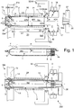
- Fig. 1 shows a first embodiment of a MAS-NMR rotor system 100 according to the invention, comprising a rotor 1, in which a measurement substance is arranged in solid or semi-solid form (such as a powder or gel), and a stator 2.
- a measurement substance is arranged in solid or semi-solid form (such as a powder or gel)
- a stator 2 (together with parts of a stator holder 32), in Fig. 1 Middle of rotor 1 and in Fig. 1
- the entire MAS-NMR rotor system 100 with rotor 1 and stator 2 (together with parts of the stator holder 32) is shown below.
- the MAS-NMR rotor system 100 and the stator holder 32 are part of a probe head arrangement 200 according to the invention.
- the stator 2 comprises a first pneumatic radial bearing 3, a second pneumatic radial bearing 4 and a pneumatic axial bearing 5.
- the rotor 1 is rotatably mounted within the stator 2 about an axis of rotation RA.
- the rotor 1 comprises a circular cylindrical section 6 and an end section 7, which is the in Fig. 1 the left (front), closed end of the rotor 1 forms.
- the end section 7 runs here in the shape of a truncated cone and tapers towards the left-hand end; a cone angle ⁇ of the end section 7 with respect to the axis of rotation RA is approx. 30 ° here; generally 10 ° to 45 ° are preferred.
- an opening 8 is formed which is closed with a cap 9, so that measurement substance filled into the rotor 1 is not lost during an NMR experiment.
- Counter-structures 9a for example baffles (only indicated schematically), through which the rotation of the rotor 1 about the axis of rotation RA can be effected with a suitable gas flow of a pneumatic drive 22, are formed on the cap 9.
- the outer radius R4 of the cap 9 corresponds approximately to the radius R1 of the rotor 1 in the circular cylindrical section 6.
- the circular cylindrical section 6 has the (outer) radius R1 and forms a first bearing surface 10 for the first pneumatic radial bearing 3.
- Stator-side nozzle outlet openings 11 (at the inner end of the nozzle outlet bore) of the first radial bearing 3 are arranged on a radius r1 with respect to the axis of rotation RA.
- the second pneumatic radial bearing 4 has nozzle outlet openings 12 at a radius r2.
- the second radial bearing 4 not only supports the rotor 1 radially in the area of the front end, but can also contribute to holding the rotor 1 axially if the flow conditions are appropriately designed.
- the rotor 1 At the left-hand (front) axial end of the rotor 1, the rotor 1 forms a third bearing surface 14 which, together with a nozzle outlet opening 15, forms the pneumatic axial bearing 5.
- the stator-side parts of the second radial bearing 4 and the axial bearing 5 surround the third bearing surface 14 and here also the rest of the end section 7 in the shape of a cup Radial bearing 4, depending on the design, but also, at least in part, from the first radial bearing 3 and additionally possibly existing temperature control air to the outside. This serves to avoid or minimize a counter pressure which would counteract the holding force of the axial bearing 5.
- the end section 7 extends here over approximately 6.5% of the entire length of the rotor 1 (including the cap 9); generally preferred are 5% to 25%.
- stator-side parts of the second radial bearing 4 and of the pneumatic axial bearing 5 are arranged such that they extend radially approximately as far as the radius R1 of the circular cylindrical section 6.
- r2 ⁇ R1 applies here.
- stator-side parts of the first radial bearing 3 occupy a space beyond R1.
- the stator 2 preferably forms a unitary component, as in FIG Fig. 1 can be seen (but it is also possible to form the stator 2 with parts that are separate from one another).
- the stator 2 has a covering element 16, which has a first bearing base 17, in which the stator-side part of the first radial bearing 3 is formed, and a second bearing base 18, in which the stator-side part of the second radial bearing 4 (and here also the stator-side part of the pneumatic Axial bearing 5) is formed, connects to each other mechanically.
- the enveloping element 16 has a front section 19, which adjoins the second bearing base 18 and has a (largest) outer diameter ADV, and here a rear section 20, with a (largest) outer diameter ADH, which adjoins the first bearing element 17 connects.
- the (largest) outside diameter of the first bearing base 17 is AD1
- the (largest) outside diameter of the second bearing base 18 is AD2.
- the stator 2 of the MAS-NMR rotor system 100 protrudes with the second bearing base 18 and the front section 19 of the casing element 16 through an RF coil arrangement 21 which has a smallest inner diameter IDS.
- the front section 19 has an axial length LV which here is slightly greater than the axial length LS of the HF coil arrangement 21.
- the HF coil arrangement is designed here as a self-supporting wire coil (without a coil carrier).
- the rotor 1 or the substance to be measured can move radially very close to the HF coil arrangement 21.
- AD1> IDS so that the first radial bearing 3 can be designed with a large radius r1 of the nozzle outlet openings 11, and AD1> IDS can also be set up in order to improve the (rear) radial bearing of the rotor 1.
- stator 2 For maintenance purposes it is easily possible to pull the stator 2 axially out of the HF coil arrangement 21 (here to the right) and after a repair (or replacement, if necessary) push it back into the HF coil arrangement 21 (here to the left), without removing the RF coil arrangement 21 from the MAS-NMR probe head arrangement 200.
- a counter bearing 35 can be provided, which pushes the rotor 1 onto the axial bearing 5 at the end here on the cap side, for example with a gas flow through a nozzle outlet opening 36.
- the counter-bearing 35 can be formed in a foldable or displaceable stator part which can be folded away or pushed away for a stator change or can be mounted, for example screwed on, each time the rotor is changed (not shown in detail).
- the counter bearing 35 is integrated into a closure cover 37, with which the stator 2 is closed when the rotor 1 is inserted; the closure cover 37 here also has air outlet openings 34a.
- the stator 2 is mounted in a stator holder 32 which forms a stator bearing 41 for the stator 2, into which the stator 2 can be inserted and removed axially (parallel to the axis of rotation RA); is shown in Fig. 1 above and below the introduced state.
- the stator bearing 41 here comprises a front part 41a which, in the embodiment shown, engages around the second bearing base 18 and forms a radial delimitation 32a for any radial movement of the stator 2.
- the stator bearing 41 here comprises a rear part 41b which, in the embodiments shown, engages around the first bearing base 17 and likewise forms a radial delimitation 32a.
- the rear part 41b also forms an axial stop 32b for the stator 2, against which a shoulder 42 of the first bearing base 17 rests.
- the HF coil arrangement 21 is arranged between the parts 41a, 41b of the stator bearing 41, radially directly adjacent to the casing element 16, and is fastened in a manner not shown in the MAS-NMR probe head arrangement 200, for example on the stator holder 32 (but not on stator 2).
- seals (sealing rings) 30, 31 are arranged, here O-rings elastic material such as rubber. These press here circumferentially on the outer sides of the second bearing base 18 and the first bearing base 17.
- an evacuated space 33 which is also delimited radially on the inside by the enveloping element 16, is sealed.
- the contained HF coil arrangement 21 can be tempered with good thermal insulation, in particular to a cryogenic temperature of, for example, 20 K.
- the seals 31, 30 function in the embodiment of FIG Fig. 1 as stationary (ie immovable in the stator holder 32) securing parts 61, which at the same time have the function of elastic elements 44, which radially brace the inserted stator 2 and thereby fix the stator 2 axially in a frictional connection, insofar as this is necessary in normal operation with regard to the expected forces is required. With greater force, however, the stator 2 can be pulled out axially (here to the right), for example for maintenance, without further mechanisms having to be loosened. It should be noted that when the stator 2 is reinserted into the stator holder 32 at the seals 31, 30, a certain force (mechanical resistance) must be overcome.
- a gas power supply 38 is also connected to the stator 2, here to the first bearing base 17.
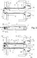
- FIG. 11 shows a second embodiment of a MAS-NMR rotor system 100 according to the invention, which largely corresponds to the embodiment of FIG Fig. 1 so that only the essential differences are shown here.
- the stator 2 (with parts of a stator holder 32) is shown at the top, the rotor 1 in the middle, and the MAS-NMR rotor system 100 with rotor 1 and stator 2 at the bottom.
- the MAS-NMR rotor system 100 and the stator holder 32 are part of a probe head assembly 200 for the invention.
- the rotor 1 has an end section 7 which is designed in the form of a circular cylinder in a front part 7a and is conical (frustoconical) in a rear part 7b, which leads to the circular cylindrical section 6.
- the end section 7 forms the second bearing surface 13 of the second pneumatic radial bearing 4 opposite the nozzle outlet openings 12 in the area of the circular cylindrical front part 7a.
- the radius R2 of the second bearing surface 13 is equal to the radius R3 of the third bearing surface 14 of the pneumatic axial bearing 5, opposite the nozzle outlet opening 15.
- Both R2 and R3 are significantly smaller than the radius R1 of the first bearing surface 10 opposite the nozzle outlet openings 11 of the first radial bearing 3
- Part of the end section 7 is formed here by a cap attachment 39 of the rotor 1.
- Counter-structures 39a for example baffles, are formed on the cap attachment 39 for a drive gas flow of a drive 22 with which the rotor 1 can be set in rotation about the axis of rotation RA.
- the nozzle outlet openings 12 of the second radial bearing 4 are at a radius r2 significantly smaller than the radius r1 of the nozzle outlet openings 11 of the first radial bearing 3, and also significantly smaller than the (outer) radius R1 of the cylindrical section 6, so that here too a very compact design is achievable, which can easily be pushed axially from the side into an RF coil arrangement 21.
- the RF coil arrangement 21 is formed here with a tubular coil carrier 21a, on which the conductor elements 21b of the RF coil arrangement 21 are arranged on the outside.
- the stator 2 has temperature control gas nozzles 51, with which a desired temperature can be set in the stator 2 around the rotor 1, and thus also in the rotor 1.
- the measurement substance can be moderately cooled in the rotor 1 in order to prevent the denaturation of proteins during an NMR measurement, for example at approx. 0 ° C.
- compressed gas nozzles 52 are provided here, with which the pressure on a baffle surface 53 of the rotor 1, formed here on the cap 9, can be adjusted in order to secure the axial position of the rotor 1 during the rotation about the axis of rotation RA.
- an equal or greater gas flow can be used on the second radial bearing 4 than on the first radial bearing 3 in order to achieve approximately the same radial bearing rigidity.
- the second radial bearing 4 can be subjected to a higher pressure than the first radial bearing.
- a counter bearing can also be provided in this embodiment (not shown, but see Fig. 1 and Fig. 3 ).
- a removable securing part 43 is provided which engages behind the stator 2 on the first bearing base 17.
- the detachable securing part 43 is shown in a securing position screwed to the stator holder 32, see the screws 45.
- the securing part 43 presses with elastic elements 44, here springs or alternatively elastomer elements, from behind against the stator 2, causing it to be attached to the stator 2 axial stop 32b is fixed adjacent.
- the stator 2 is therefore elastically braced against the axial stop 32b.
- the screws 45 can be loosened and the securing part 43 (including springs) can be removed.
- the removable securing part 43 also includes a gas power supply 38 here.
- the cladding tube 16 here does not have a rear section that would be further radially than a front section 19, so here the front section 19 (which can be inserted into the RF coil arrangement) extends over the entire length of the cladding tube 16.
- FIG. 3 shows a third embodiment of an inventive MAS-NMR rotor system 100, which largely corresponds to the embodiment of FIG Fig. 1 so that only the essential differences are shown here.
- the stator 2 is again shown, but in a state only partially pushed into the stator holder 32 in the insertion direction ER, with the securing part 50 not yet mounted.
- the rotor 1 is shown in the middle, and the entire MAS-NMR rotor system at the bottom 100 with rotor 1 and stator 2.
- the MAS-NMR rotor system 100 and the stator holder 32 are part of a probe head arrangement 200 for the invention.
- the rotor 1 again has an end section 7 with a circular cylindrical front part 7a and a conical rear part 7b (cf. Fig. 2 ), but without using a cap attachment at the front end.
- the pneumatic drive 22 engages a cap 9 at the rear end of the rotor 1.
- the cladding tube 16 here does not have a rear section which would be further radially than a front section 19, so the front section 19 (which can be inserted into the RF coil arrangement 21) extends here over the entire length of the cladding tube 16.
- the securing part 50 serves to hold the stator 2 in the stator bearing 41 in an axially fully retracted state (with respect to the insertion direction ER or along the axis of rotation RA) (cf. Fig. 3 below, with shoulder 42 and axial stop 32b resting against one another) so that the stator 2 cannot move axially during a measurement.
- the securing part 50 has lugs 50a which can be inserted into grooves 17a on the first bearing base 17.
- the securing part 50 can be screwed to the stator holder 32 by means of screws 45, cf. Fig. 3 below for the screwed-in state.
- the stator 2 is clamped in the radial direction RR.
- a further securing of the stator 2 in the axial direction in the stator bearing 41 is thereby also achieved by frictional connection, beyond the effect of the seals or sealing rings 30, 31.
- the lugs 50a also engage behind the first bearing base 17 in the grooves 17a with respect to the axial direction, as a result of which additional securing occurs.
- the securing part 50 here also contains the gas flow supply 38, the seals 17b sealing off the supply gas flow.
- a counter-bearing 35 is set up in the closure cover 37 in that the outflow of the drive air from the drive 22 is limited, so that a counterpressure is built up which pushes the rotor 1 onto the axial bearing 5.
- an adjustable gas flow limitation device here a variable diaphragm 55, is provided in a gas outlet channel 54.
- Fig. 4 shows, in a schematic sectional view, an embodiment of a probe head arrangement 200 according to the invention, in which an MAS-NMR rotor system 100 according to the invention has been installed, as in FIG Fig. 3 shown.
- the probe head arrangement 200 comprises a stator 2 in which a rotor 1 is mounted rotatably about an axis of rotation RA; the rotor 1 is in Fig. 4 has just been changed and is therefore only partially pushed axially into the stator 2.
- the rear end of the rotor 1 is closed with a cap 9.
- the stator 2 has two bearing bases 17, 18 which are mechanically connected via the casing element 16.
- the probe head arrangement 200 has an RF coil arrangement 21, the smallest inner diameter IDS of the RF coil arrangement 21 being greater than the (largest) outer diameter AD2 of the second bearing base 18 and the (largest) outer diameter ADV in a front section 19 of the enveloping element 16 (which here encompasses the entire length of the enveloping element 16).
- the stator 2 can be guided through the RF coil arrangement 21 during assembly or for maintenance purposes with the fuse component 50 removed.
- the stator 2 In the inserted (pushed in) state, the stator 2 is held in a stator holder 32, which for this purpose forms a stator bearing.
- the bearing is designed in such a way that the axis of rotation RA is aligned at the magic angle of 54.7 ° with respect to a magnetic field B 0 running vertically here.
- the radially outwardly gas-tight stator 2 with gas-tight enveloping element 16 is sealed here in the area of the bearing bases 17, 18 with the seals 30, 31 relative to the stator holder 32, so that the stator 2 or the enveloping element 16 also delimits a space 33; the space 33 is here also delimited by the stator holder 32 and further walls not shown in detail.
- a vacuum is set up here in order to thermally isolate the HF coil arrangement 21.
- a cryogenic temperature for example 77 K, corresponding to liquid nitrogen at normal pressure or, when cooling, for example with liquid or gaseous helium, also lower temperatures, in particular 40 K, 20 K or even in the range around 4.2 K, corresponding to liquid helium at normal pressure
- the measurement substance 40 in the rotor 1 remains at a temperature close to room temperature or at a temperature in the range from -250 ° C to + 1000 ° C, in particular from -50 ° C to + 150 ° C and particularly preferably in a temperature range from 0 ° C to + 50 ° C.
- the rotor 1 rotates in the stator 2 around the axis of rotation RA, typically at a frequency of 10 kHz or more, in particular at speeds in the range from 1 kHz to vs / (2 ⁇ R1), where vs is the speed of sound of the gas surrounding the rotor 1 at present Pressure / temperature conditions is, and the RF coil arrangement 21 radiates RF pulses into the measurement substance 40 in the rotor 1 and / or receives RF signals from the measurement substance 40.
- the strong static magnetic field B 0 acts (with vertical orientation in Fig. 4 ) on the substance 40 to be measured.
- All gas flows are preferably led out at the two ends of the axially removable stator 2 so that it can be easily collected and returned. This is particularly advantageous for low-temperature MAS in order not to lose it into the room air when operating with He gas.
- the gas is preferably transferred directly to a dewar so that it does not heat up unnecessarily and an encapsulated gas circuit becomes possible, which only has to compensate (after-cool) the line losses and the friction in the rotor system 100.
- the after-cooling is preferably carried out with heat exchangers and compression of the gas at room temperature (not shown in detail).
Landscapes
- Physics & Mathematics (AREA)
- Condensed Matter Physics & Semiconductors (AREA)
- General Physics & Mathematics (AREA)
- Spectroscopy & Molecular Physics (AREA)
- High Energy & Nuclear Physics (AREA)
- Magnetic Bearings And Hydrostatic Bearings (AREA)
- Connection Of Motors, Electrical Generators, Mechanical Devices, And The Like (AREA)
Description
Die Erfindung betrifft ein MAS-NMR-Rotorsystem, umfassend einen Rotor zur Aufnahme einer Messsubstanz und einen Stator zur Lagerung des Rotors drehbar um eine Rotationsachse,
- mit einem ersten pneumatischen Radiallager, umfassend erste Düsenaustrittsöffnungen im Stator bei einem Radius r1 und eine erste Lagerfläche an einem kreiszylinderförmigen Abschnitt des Rotors bei einem Radius R1,
- mit einem zweiten pneumatischen Radiallager, umfassend zweite Düsenaustrittsöffnungen im Stator bei einem Radius r2 und eine zweite Lagerfläche am Rotor bei einem Radius R2, gemessen gegenüber den zweiten Düsenaustrittsöffnungen im Stator,
- und mit einem pneumatischen Axiallager, umfassend wenigstens eine Düsenaustrittsöffnung im Stator und eine dritte Lagerfläche an einem axialen Ende des Rotors, wobei die dritte Lagerfläche orthogonal zur Rotationsachse verläuft und einen Außenradius R3 aufweist.
- with a first pneumatic radial bearing, comprising first nozzle outlet openings in the stator at a radius r1 and a first bearing surface on a circular cylindrical section of the rotor at a radius R1,
- with a second pneumatic radial bearing, comprising second nozzle outlet openings in the stator at a radius r2 and a second bearing surface on the rotor at a radius R2, measured opposite the second nozzle outlet openings in the stator,
- and with a pneumatic axial bearing, comprising at least one nozzle outlet opening in the stator and a third bearing surface at one axial end of the rotor, the third bearing surface running orthogonally to the axis of rotation and having an outer radius R3.
Ein solches Rotorsystem ist beispielsweise aus der
Kernspinresonanz(=NMR, nuclear magnetic resonance)-Spektroskopie ist ein leistungsfähiges Verfahren der instrumentellen Analytik, mit der die chemische Zusammensetzung von Messsubstanzen (Proben) untersucht werden kann.Nuclear magnetic resonance (= NMR) spectroscopy is a powerful method of instrumental analysis with which the chemical composition of substances to be measured (samples) can be examined.
Dabei wird die Messsubstanz einem starken, statischen Magnetfeld ausgesetzt, wodurch es zur Ausrichtung von Kernspins in der Messsubstanz kommt. Nach Einstrahlung von HF(=Hochfrequenz)-Pulsen werden von der Messsubstanz ausgehende HF-Signale aufgenommen und zur Bestimmung der chemischen Zusammensetzung ausgewertet.The substance to be measured is exposed to a strong, static magnetic field, which leads to the alignment of nuclear spins in the substance to be measured. After the irradiation of HF (= high frequency) pulses, HF signals emanating from the substance to be measured are recorded and evaluated to determine the chemical composition.
Bei der NMR-Spektroskopie von Festkörperproben kommt es zu einer erheblichen Linienverbreiterung in gemessenen NMR-Spektren aufgrund von anisotropen Wechselwirkungen zwischen Kernen in der Probe. Für Festkörperproben ist es bekannt, die Messsubstanz während der NMR-Messung unter dem so genannten "Magischen Winkel" von ca. 54,7° gegen die Richtung des statischen Magnetfelds zu rotieren. Dadurch kann eine Linienverbreiterung durch dipolare Wechselwirkungen, Quadrupolwechselwirkungen und den anisotropen Teil der chemischen Verschiebung reduziert bzw. bei ausreichend hohen Rotationsfrequenzen ausgelöscht werden.In the case of NMR spectroscopy of solid samples, there is a considerable broadening of the lines in the measured NMR spectra due to anisotropic interactions between nuclei in the sample. For solid samples it is known to rotate the measurement substance during the NMR measurement at the so-called "magic angle" of approx. 54.7 ° against the direction of the static magnetic field. As a result, line broadening due to dipolar interactions, quadrupole interactions and the anisotropic part of the chemical shift can be reduced or canceled at sufficiently high rotation frequencies.
Die Messsubstanz wird hierfür typischerweise in ein im Wesentlichen zylindrisches Probenröhrchen, genannt Rotor, gefüllt und in einen Stator verbracht. Der Rotor wird relativ zum Stator in Rotation versetzt, wobei der Rotor im Stator schwebt; hierfür werden geeignete Gasströme eingesetzt. Um HF-Pulse in die Messsubstanz einzustrahlen und/oder HF-Signale aus der Messsubstanz zu empfangen, ist eine HF-Spulenanordnung vorgesehen, die den Stator umgibt.For this purpose, the substance to be measured is typically filled into an essentially cylindrical sample tube, called a rotor, and placed in a stator. The rotor is set in rotation relative to the stator, the rotor floating in the stator; suitable gas flows are used for this. In order to radiate RF pulses into the measurement substance and / or to receive RF signals from the measurement substance, an RF coil arrangement is provided which surrounds the stator.
Aus der
Bei diesem NMR-MAS-Probenkopf befinden sich der Rotor und die HF-Spulenanordnung in der gleichen Umgebung bei Raumtemperatur. Um das Signal zu Rauschverhältnis der NMR-Messung zu verbessern, kann die HF-Spulenanordnung gekühlt werden. Um eine effiziente Kühlung zu erreichen, sollte dafür die HF-Spulenanordnung mit einer Isolation, etwa einer Vakuumisolation, versehen werden. Ein ähnlicher Aufbau ist bei der Messung von Messproben bei sehr hohen Temperaturen von Vorteil, bei denen der Messraum z.B. durch eine Vakuumisolation von der HF-Spulenanordnung thermisch getrennt werden kann.In this NMR-MAS probe head, the rotor and the RF coil arrangement are in the same environment at room temperature. In order to improve the signal-to-noise ratio of the NMR measurement, the RF coil arrangement can be cooled. In order to achieve efficient cooling, the HF coil arrangement should be provided with insulation, for example vacuum insulation. A similar setup is advantageous when measuring samples at very high temperatures, at which the measuring room can be thermally separated from the HF coil arrangement, e.g. by vacuum insulation.
Eine solche Isolation vergrößert aber den radialen Abstand zwischen dem Rotor bzw. der Messsubstanz und der HF-Spulenanordnung, d.h. die HF-Spulenanordnung muss mit einem größeren Durchmesser gewählt werden, von dem nur noch ein kleinerer Anteil mit Probensubstanz gefüllt ist. Weiterhin muss die HF-Spulenanordnung axial gegenüber dem Stator isoliert werden, was im Falle von radial ausgedehnten statorseitigen Radiallagerteilen zur Verkürzung der Spulenlänge und somit Reduktion des Messvolumens bei gleichem Messprobenvolumen führt. Bei einer dergestalteten Ausführung würden die Performance-Verluste aufgrund der geometrischen Nachteile den erzielbaren Gewinn durch die Reduktion des Rauschens aufgrund der gesenkten Temperatur der HF-Spulenanordnung weitestgehend aufheben oder sogar übersteigen. Zudem ist eine solche Isolation nur sehr schwer nachträglich in einem MAS-NMR-Probenkopf zu installieren.Such an insulation increases the radial distance between the rotor or the measuring substance and the HF coil arrangement, i.e. the HF coil arrangement must be selected with a larger diameter, of which only a smaller proportion is filled with sample substance. Furthermore, the HF coil arrangement must be axially isolated from the stator, which in the case of radially expanded radial bearing parts on the stator side leads to a shortening of the coil length and thus a reduction in the measurement volume with the same measurement sample volume. In such an embodiment, the performance losses due to the geometric disadvantages would largely cancel out or even exceed the gain that can be achieved by reducing the noise due to the lowered temperature of the RF coil arrangement. In addition, such an insulation is very difficult to retrofit in a MAS-NMR probe head.
Ein Rotorsystem mit zwei Radiallagern gleicher Radien und einem konusförmigen Bodenlager, das schräg angeblasen wird, ist aus der
Aus
Der Erfindung liegt die Aufgabe zugrunde, ein MAS-NMR-Rotorsystem zur Verfügung zu stellen, mit dem eine HF-Spulenanordnung radial besonders nahe an eine Messsubstanz im Rotor heranrücken kann und die MAS-NMR-Rotorensystem leicht in die HF-Spulenanordnung ein- und ausführbar ist.The invention is based on the object of providing a MAS-NMR rotor system with which an RF coil arrangement can move radially particularly close to a measurement substance in the rotor and the MAS-NMR rotor system can easily move into and out of the RF coil arrangement is executable.
Diese Aufgabe wird auf überraschend einfache und wirkungsvolle Weise gelöst durch ein Rotorsystem der eingangs genannten Art, das dadurch gekennzeichnet ist, dass das zweite Radiallager an einem Endabschnitt des Rotors ausgebildet ist, der einen gegenüber dem kreiszylinderförmigen Abschnitt kleineren oder weg vom kreiszylindrischen Abschnitt sich verkleinernden Radius aufweist, so dass gilt R2 < R1 und weiterhin r2 < r1, und dass die dritte Lagerfläche an einem dem kreiszylinderförmigen Abschnitt abgewandten Ende des Endabschnitts ausgebildet ist, so dass weiterhin gilt R3 ≤ R2.This object is achieved in a surprisingly simple and effective way by a rotor system of the type mentioned at the beginning, which thereby is characterized in that the second radial bearing is formed at an end portion of the rotor which has a smaller radius than the circular cylindrical portion or which decreases away from the circular cylindrical portion, so that R2 <R1 and furthermore r2 <r1, and that the third bearing surface on an end of the end section facing away from the circular cylindrical section, so that R3 R2 continues to apply.
Gemäß der Erfindung ist vorgesehen, dass im Bereich des Endabschnitts, wo das zweite Radiallager ausgebildet ist, der Rotor gegenüber dem kreiszylindrischen Abschnitt verengt ist, entsprechend R2 < R1. Dadurch wird ein radialer Raum für die Ausbildung des statorseitigen Teils des zweiten Radiallagers zur Verfügung gestellt. Entsprechend kann das zweite Radiallager statorseitig enger ausgebildet werden als das erste Radiallager, gemäß r2 < r1.According to the invention it is provided that in the area of the end section where the second radial bearing is formed, the rotor is narrowed relative to the circular cylindrical section, corresponding to R2 <R1. This provides a radial space for the formation of the stator-side part of the second radial bearing. Correspondingly, the second radial bearing on the stator side can be made narrower than the first radial bearing, according to r2 <r1.
Das erfindungsgemäße MAS-NMR-Rotorsystem, umfassend Rotor und Stator, kann dann einenends (vorne, im Bereich des zweiten pneumatischen Radiallagers) radial enger ausgebildet werden als anderenends (hinten, im Bereich des ersten pneumatischen Radiallagers). Dadurch kann das Rotorsystem gut mit dem vorderen Ende (also mit dem vorderen Endabschnitt und Teilen des kreiszylinderförmigen Abschnitts) in einen radial begrenzten Raum eingeführt werden, in welchen das hintere Ende (mit dem ersten pneumatischen Radiallager) nicht mehr hineinpassen würde.The MAS-NMR rotor system according to the invention, comprising rotor and stator, can then be made radially narrower at one end (front, in the area of the second pneumatic radial bearing) than at the other end (rear, in the area of the first pneumatic radial bearing). As a result, the front end of the rotor system (i.e. with the front end section and parts of the circular cylindrical section) can be inserted into a radially limited space into which the rear end (with the first pneumatic radial bearing) would no longer fit.
Durch die erfindungsgemäße Geometrie kann eine HF-Spulenanordnung (ein HF-Spulensystem), in das der Stator und der Rotor in axialer Richtung eingeführt werden, sehr nahe an den Rotor bzw. die Messsubstanz heranrücken. Das nutzbare Volumen für Messsubstanz im Inneren der HF-Spulenanordnung wird nicht durch die radiale Breite des am zylindrischen Abschnitt wirkenden ersten pneumatischen Radiallagers, sondern nur durch die radiale Breite des am radial kleineren Endabschnitt angeordneten zweiten pneumatischen Radiallagers (oder durch den kreiszylinderförmigen Abschnitt selbst, sollte dieser eine größere radiale Breite aufweisen) bestimmt. Insgesamt ist ein sehr kompakter Aufbau des Rotorsystems möglich.Due to the geometry according to the invention, an HF coil arrangement (an HF coil system) into which the stator and the rotor are inserted in the axial direction can move very close to the rotor or the substance to be measured. The usable volume for substance to be measured inside the RF coil arrangement is not determined by the radial width of the first pneumatic radial bearing acting on the cylindrical section, but only by the radial width of the second radial bearing located on the radially smaller end section pneumatic radial bearing (or by the circular cylindrical section itself, this should have a larger radial width). Overall, a very compact structure of the rotor system is possible.
Wenn das Rotorsystem axial in eine HF-Spulenanordnung eingeführt wird, ist ein Austausch (evtl. auch eine Nachrüstung) des Rotorsystems in diese HF-Spulenanordnung im Allgemeinen sehr leicht möglich. Der Stator kann insbesondere gehandhabt (etwa eingeschoben oder herausgezogen) werden, ohne die HF-Spulenanordnung aus ihrem Probenkopf (auch genannt Probenkopfanordnung) entfernen zu müssen. Eine Isolation, etwa eine Vakuumisolation, für die HF-Spulenanordnung ist mittels oder unter Beteiligung des MAS-NMR-Rotorsystems sehr einfach einzurichten, insbesondere mit einer sich im Wesentlichen in axialer Richtung mit konstantem Innenradius erstreckenden Innenwand. Eine solche Isolation ist in Einzelfällen auch nachträglich leicht einzurichten, und besonders gut mit dem erfindungsgemäßen Rotorsystem nutzbar. Insbesondere kann ein Teil des Stators (etwa ein Hüllelement) als radial innenliegender Teil bzw. Wand einer Isolation einer HF-Spulenanordnung genutzt werden (mehr dazu unten).If the rotor system is introduced axially into an HF coil arrangement, it is generally very easy to exchange (possibly also retrofit) the rotor system in this HF coil arrangement. In particular, the stator can be handled (e.g. pushed in or pulled out) without having to remove the RF coil arrangement from its probe head (also called probe head arrangement). An insulation, for example a vacuum insulation, for the HF coil arrangement can be set up very easily by means of or with the participation of the MAS-NMR rotor system, in particular with an inner wall extending essentially in the axial direction with a constant inner radius. In individual cases, such an insulation is easy to set up afterwards and can be used particularly well with the rotor system according to the invention. In particular, a part of the stator (for example a covering element) can be used as a radially inner part or wall of an insulation of an HF coil arrangement (more on this below).
Eine Verkleinerung des Radius R2 im Endabschnitt gegenüber dem Radius R1 im kreiszylinderförmigen Abschnitt entlang der axialen Richtung kann kontinuierlich oder abschnittsweise kontinuierlich oder auch mit einer oder mehreren Stufen erfolgen. Weiterhin kann der Übergang vom kreiszylindrischen Abschnitt zum Endabschnitt kontinuierlich oder auch mit einer Stufe erfolgen. Man beachte, dass die zweite Lagerfläche parallel zur Rotationsachse verlaufen kann, oder auch mit einem Konuswinkel zur Rotationsachse; das zweite Radiallager (und auch das erste Radiallager) hält den Rotor in radialer Richtung in Position. Der Radius Ri der Lagerflächen bezieht sich auf die Position mittig bezüglich der zugehörigen Düsenaustrittsöffnungen; im Falle von mehreren Düsenaustrittsöffnungen an verschiedenen axialen Positionen bezieht sich der Radius der Lagerflächen auf einen mittlere axiale Position der Düsenaustrittsöffnungen. Entsprechendes gilt für die Radien ri.A reduction of the radius R2 in the end section compared to the radius R1 in the circular cylindrical section along the axial direction can take place continuously or continuously in sections or also with one or more steps. Furthermore, the transition from the circular cylindrical section to the end section can take place continuously or with one step. Note that the second bearing surface can run parallel to the axis of rotation, or also with a cone angle to the axis of rotation; the second radial bearing (and also the first radial bearing) holds the rotor in position in the radial direction. The radius R i of the bearing surfaces relates to the position in the center with respect to the associated nozzle outlet openings; in the case of several nozzle outlet openings at different axial positions the radius of the bearing surfaces relates to a mean axial position of the nozzle outlet openings. The same applies to the radii r i .
Eine bevorzugte Ausführungsform des erfindungsgemäßen Rotorsystems sieht vor, dass der Endabschnitt zumindest teilweise kreiszylinderförmig ausgebildet ist. Dies ermöglicht statorseitig einen besonders einfachen Aufbau. Zudem können die radiale Lagerfunktion des zweiten Radiallagers und die axiale Lagerfunktion des Axiallagers voneinander getrennt eingestellt werden, wenn das zweite Radiallager im kreiszylinderförmigen Bereich des Endabschnitts eingereichtet ist. Der Endabschnitt kann vollständig kreiszylinderförmig ausgebildet sein, mit einer (rechtwinkligen) Stufe am Übergang zum kreiszylinderförmigen Abschnitt. Bei einer vorteilhaften Bauform weist der Endabschnitt einen kegelstumfförmigen Teil (Bereich) zum kreiszylinderförmgen Anbschnitt hin und einen kreiszylinderflörmigen Teil (Bereich) zum Axiallager hin auf.A preferred embodiment of the rotor system according to the invention provides that the end section is at least partially in the form of a circular cylinder. This enables a particularly simple structure on the stator side. In addition, the radial bearing function of the second radial bearing and the axial bearing function of the axial bearing can be set separately from one another when the second radial bearing is positioned in the circular cylindrical area of the end section. The end section can be completely circular-cylindrical, with a (right-angled) step at the transition to the circular-cylindrical section. In an advantageous design, the end section has a frustoconical part (area) towards the circular cylindrical section and a circular cylindrical part (area) towards the axial bearing.
Bei einer anderen Ausführungsform ist der Endabschnitt zumindest teilweise kegelstumpfförmig ausgebildet. Dies ermöglicht einen einfachen und großvolumigen Aufbau des Rotors. Der Endabschnitt kann insbesondere vollständig kegelstumpfförmig ausgebildet sein. Wenn das zweite Radiallager im kegelstumpfförmigen Bereich des Endabschnitts ausgebildet ist, kann das zweite Radiallager zusätzlich zum Axiallager zur axialen Lagerfunktion beitragen. Zudem kann das Einführen des Rotors in den Stator durch den als Führung wirkenden kegelstumpfförmigen Verlauf des Rotors erleichtert werden. Weiterhin wird die Bruchtendenz des Rotors an einem konischen Übergang bei Belastungen im Betrieb gegenüber einer rechtwinkligen Stufe, etwa bei einem vollständig kreiszylinderförmigem Endabschnitt, reduziert.In another embodiment, the end section is at least partially frustoconical. This enables a simple and large-volume construction of the rotor. The end section can in particular be completely frustoconical. If the second radial bearing is formed in the frustoconical area of the end section, the second radial bearing can contribute to the axial bearing function in addition to the axial bearing. In addition, the introduction of the rotor into the stator can be facilitated by the frustoconical profile of the rotor acting as a guide. Furthermore, the tendency of the rotor to break at a conical transition under loads during operation is reduced compared to a right-angled step, for example in the case of a completely circular-cylindrical end section.
Bevorzugt ist eine Weiterbildung dieser Ausführungsform, wobei der Endabschnitt zumindest teilweise unter einem Winkel α gegenüber der Rotationsachse verläuft, mit 15° ≤ α ≤ 45°. Dieser Winkelbereich für einen kegelstumpfförmigen Endabschnitt (oder einem kegelstumpfförmigen Teil des Endabschnitts) ist in der Praxis bewährt, insbesondere um eine ausreichende radiale Lagerfunktion zu erzielen.A further development of this embodiment is preferred, the end section at least partially running at an angle α with respect to the axis of rotation, with 15 °
Eine andere, vorteilhafte Ausführungsform sieht vor, dass der Stator die dritte Lagerfläche und zumindest einen angrenzenden Teil des Endabschnitts, bevorzugt den gesamten Endabschnitt, becherförmig umschließt, wobei im Bereich der dritten Lagerfläche und/oder des Endabschnittes Luftaustrittsöffnungen im Stator vorgesehen sind. Dadurch lässt sich der Gasstrom (insbesondere für die radiale und axiale Lagerfunktion) besonders gut kontrollieren, und auch hohe Drehzahlen des Rotors können eingestellt und sicher beherrscht werden.Another advantageous embodiment provides that the stator encloses the third bearing surface and at least an adjoining part of the end section, preferably the entire end section, in a cup-shaped manner, with air outlet openings being provided in the stator in the area of the third bearing surface and / or the end section. As a result, the gas flow (in particular for the radial and axial bearing function) can be controlled particularly well, and high speeds of the rotor can also be set and safely controlled.
Bei einer bevorzugten Ausführungsform ist vorgesehen, dass der Endabschnitt sich über 1/4 der Länge des Rotors oder weniger erstreckt und/oder sich mindestens über 1/20 der Länge des Rotors erstreckt. Falls der Rotor eine Verschlusskappe oder auch einen Kappenaufsatz aufweist, gehören diese bei der Bestimmung der Länge des Rotors zu diesem dazu. Durch eine Ausdehnung des Endabschnitts auf 1/4 der Länge des Rotors oder weniger ist der kreiszylinderförmige Abschnitt entsprechend lang, und das für Messsubstanz zur Verfügung stehende Volumen kann sehr groß gewählt werden. Durch eine Ausdehnung des Endabschnitts auf wenigstens 1/20 der Länge kann eine gute mechanische Stabilität und insbesondere eine hohe Drehzahl erreicht werden.In a preferred embodiment it is provided that the end section extends over 1/4 of the length of the rotor or less and / or extends over at least 1/20 of the length of the rotor. If the rotor has a closure cap or a cap attachment, these belong to this when determining the length of the rotor. By extending the end section to 1/4 the length of the rotor or less, the circular cylindrical section is correspondingly long, and the volume available for the substance to be measured can be selected to be very large. By extending the end section to at least 1/20 of the length, good mechanical stability and, in particular, a high speed can be achieved.
Bevorzugt ist auch eine Ausführungsform, bei der der Rotor an einem der dritten Lagerfläche abgewandten Ende eine Öffnung zur Befüllung des Rotors mit Messsubstanz aufweist, und der Rotor eine Kappe aufweist, die die Öffnung des Rotors verschließt. Durch die Öffnung kann der Rotor mit Messsubstanz befüllt werden, und durch die Kappe (die meist aus einem Kunststoff besteht) leicht verschlossen werden. Dadurch, dass die Kappe am hinteren (der dritten Lagerfläche abgewandten) Ende vorgesehen ist, kann die Kappe den vergleichsweise großen Radius R1 nutzen, was die Auslegung und das Einführen der Kappe erleichtert. Man beachte, dass alternativ auch eine Kappe zum Verschließen des Rotors im Bereich der dritten Lagerfläche vorgesehen sein kann, oder auch der Rotor beispielsweise zugeschmolzen sein kann (wodurch eine Kappe zum Verschließen nicht gebraucht wird).An embodiment is also preferred in which the rotor has an opening at an end facing away from the third bearing surface for filling the rotor with measurement substance, and the rotor has a cap which closes the opening of the rotor. The rotor can be filled with substance to be measured through the opening and easily closed by the cap (which is usually made of plastic). Because the cap is provided at the rear end (facing away from the third bearing surface), the cap can use the comparatively large radius R1, which simplifies the design and insertion of the cap. It should be noted that alternatively a cap for closing the rotor can also be provided in the area of the third bearing surface, or the rotor can also be, for example, melted shut (whereby a cap is not needed for closing).
Bei einer bevorzugten Weiterbildung dieser Ausführungsform sind an der Kappe Gegenstrukturen, insbesondere Prallflächen oder Flügelflächen oder schneckenförmige Rillen, für einen pneumatischen Antrieb des Rotors ausgebildet. In die Kappe sind die Gegenstrukturen für einen pneumatischen Antrieb besonders einfach einzubringen; die Kappe nimmt eine Doppelfunktion (Verschluss und Antrieb) war. Der pneumatische Antrieb erfolgt typischerweise über einen von den pneumatischen Lagern separat einstellbaren Gasstrom, mit eigenen Gasaustrittsöffnungen (Düsen).In a preferred further development of this embodiment, counter-structures, in particular baffle surfaces or wing surfaces or helical grooves, for a pneumatic drive of the rotor are formed on the cap. The counter-structures for a pneumatic drive are particularly easy to introduce into the cap; the cap has a double function (lock and drive). The pneumatic drive typically takes place via a gas flow that can be adjusted separately from the pneumatic bearings, with its own gas outlet openings (nozzles).
Bevorzugt ist auch eine Weiterbildung, bei der ein Außenradius R4 der Kappe im Wesentlichen dem Radius R1 entspricht. Dies trägt zu einem kompakten Bau bei. Weiterhin ist es vorteilhaft, wenn der Außenradius R4 < R1 ist. Bei dieser Ausführungsform kann der Impulsübertrag auf Flügel oder Prallflächen maximiert werden, da eine höhere Differenzgeschwindigkeit zwischen den Prallflächen und der Strömungsgeschwindigkeit des Antriebsgases erreicht werden kann.A further development is also preferred in which an outer radius R4 of the cap essentially corresponds to the radius R1. This contributes to a compact construction. It is also advantageous if the outer radius R4 <R1. In this embodiment, the transfer of momentum to the wings or baffle surfaces can be maximized, since a higher differential speed between the baffle surfaces and the flow speed of the drive gas can be achieved.
Vorteilhaft ist zudem eine Weiterbildung, bei der der kreiszylindrische Abschnitt sich vom Endabschnitt bis zur Öffnung erstreckt. Dadurch kann bei hohem Volumen für die Messsubstanz ein nahes Heranrücken an die HF-Spulenanordnung eingerichtet werden.A further development is also advantageous in which the circular cylindrical section extends from the end section to the opening. As a result, if the volume for the substance to be measured is high, it can be brought closer to the RF coil arrangement.
Vorteilhaft ist auch eine Ausführungsform, bei der der Rotor im Bereich der dritten Lagerfläche geschlossen ausgebildet ist. Dadurch ist die Form des Rotors in diesem Bereich einfach und genau vorgebbar, was die Einstellung der (vor allem axialen) Lagerkräfte erleichtert. Insbesondere ist dies von Vorteil, um die Orthogonalität der axialen Lagerfläche in Bezug auf die Rotationsachse sicherzustellen. Falls gewünscht, kann die dritte Lagerfläche auch an einem Kappenaufsatz ausgebildet sein, der am vorderen Ende des Rotors befestigt wird; dieser Kappenaufsatz kann auch Prall- oder Flügelflächen bzw. schneckenförmige Rillen für einen pneumatischen Antrieb enthalten. Alternativ kann an diesem Ende auch eine (alternative oder weitere) Öffnung und eine (alternative oder weitere) Kappe vorgesehen sein, in der die axiale Lagerfläche integriert ist. Diese (alternative oder weitere) Kappe kann auch Prall- oder Flügelflächen bzw. schneckenförmigen Rillen für einen pneumatischen Antrieb enthalten. Für eine Kappe oder einen Kappenaufsatz mit Außenradius R5 gilt bevorzugt R5≤R2.An embodiment is also advantageous in which the rotor is designed to be closed in the area of the third bearing surface. As a result, the shape of the rotor in this area can be specified simply and precisely, which makes it easier to set the (especially axial) bearing forces. This is particularly advantageous in order to ensure the orthogonality of the axial bearing surface in relation to the axis of rotation. If desired, the third bearing surface can also be formed on a cap attachment which is attached to the front end of the rotor; this cap attachment can also contain impact or wing surfaces or helical grooves for a pneumatic drive. Alternatively, an (alternative or further) opening and an (alternative or further) cap, in which the axial bearing surface is integrated, can also be provided at this end. This (alternative or additional) cap can also contain impact or wing surfaces or helical grooves for a pneumatic drive. For a cap or a cap attachment with an outer radius of R5, R5≤R2 is preferred.
Besonders bevorzugt ist auch eine Ausführungsform, die vorsieht, dass das Rotorsystem weiterhin ein Gegenlager aufweist, das dem Axiallager gegenüber liegt. Das Gegenlager kann beispielsweise ausgebildet sein
- als pneumatisches Axiallager, insbesondere mit wenigstens einer Düsenaustrittsöffnung im Stator und mit einer vierten Lagerfläche an einem axialen Ende des Rotors, die orthogonal zur Rotationsachse verläuft,
- als pneumatisches Konuslager,
- als Lager auf Basis eines passiven Gegendruckaufbaus, insbesondere mit einem Stopfen oder einer Blende,
- als Lager auf Basis eines aktiven Gegendruckaufbaus, insbesondere mit einem beweglichen Stopfen, variabler Blende oder mit Luftanblasen ohne Lagerfläche.
- as a pneumatic axial bearing, in particular with at least one nozzle outlet opening in the stator and with a fourth bearing surface at one axial end of the rotor, which runs orthogonally to the axis of rotation,
- as a pneumatic cone bearing,
- as a bearing on the basis of a passive counterpressure build-up, in particular with a stopper or a diaphragm,
- as a bearing based on an active counterpressure build-up, in particular with a movable stopper, variable diaphragm or with air blowing without a bearing surface.
Man beachte, dass das Axiallager typischerweise eine Haltekraft aufbringt (also den Rotor am vorderen Ende zum Stator zieht), während das Gegenlager typischerweise eine Gegenkraft aufbringt (also den Rotor am hinteren Ende vom Stator wegdrückt), um das Axiallager zu unterstützen, insbesondere wenn der Außenradius R3 recht klein sein sollte, insbesondere falls R3 ≤ ¾ * R1 oder sogar R3 ≤ ½*R1. Für kleine R1 kann die Haltekraft auch schon bei R3 ≤ R1 zu gering sein, um den Rotor in seinem kompletten Betriebsbereich im Stator zu halten.Note that the thrust bearing typically applies a holding force (i.e. pulls the rotor at the front end towards the stator), while the counter bearing typically applies a counterforce (i.e. pushes the rotor at the rear end away from the stator) to support the thrust bearing, especially when the The outer radius R3 should be quite small, especially if R3 ≤ ¾ * R1 or even R3 ≤ ½ * R1. For small R1, the holding force can already be too low at R3 ≤ R1 to hold the rotor in its complete operating range in the stator.
In den Rahmen der vorliegenden Erfindung fällt auch eine Probenkopfanordnung umfassend ein erfindungsgemäßes, oben beschriebenes Rotorsystem sowie eine HF-Spulenanordnung zum Einstrahlen von HF-Pulsen in die Messsubstanz im Rotor und/oder zum Empfangen von HF-Signalen aus der Messsubstanz im Rotor,
- wobei der Stator eine erste Lagerbasis umfassend einen statorseitigen Teil des ersten Radiallagers, ein Hüllelement und eine zweite Lagerbasis umfassend einen statorseitigen Teil des zweiten Radiallagers aufweist,
- wobei das Hüllelement die erste Lagerbasis und die zweite Lagerbasis miteinander verbindet,
- wobei das Hüllelement einen vorderen Abschnitt aufweist, der sich an die zweite Lagerbasis anschließt und einen größten Außendurchmesser ADV aufweist,
- und die zweite Lagerbasis einen größten Außendurchmesser AD2 aufweist,
- und der Stator im Bereich des ersten Radiallagers einen größten Außendurchmesser AD1 aufweist,
- und wobei die HF-Spulenanordnung einen kleinsten Innendurchmesser IDS aufweist,
- mit AD1 > IDS und ADV < IDS und AD2 < IDS.
- wherein the stator has a first bearing base comprising a stator-side part of the first radial bearing, a shell element and a second bearing base comprising a stator-side part of the second radial bearing,
- wherein the envelope element connects the first bearing base and the second bearing base to one another,
- wherein the enveloping element has a front section which adjoins the second bearing base and has a largest outer diameter ADV,
- and the second bearing base has a largest outer diameter AD2,
- and the stator has a largest outer diameter AD1 in the area of the first radial bearing,
- and wherein the RF coil arrangement has a smallest inner diameter IDS,
- with AD1> IDS and ADV <IDS and AD2 <IDS.
Der Stator kann bei der Montage der Probenkopfanordnung oder für Wartungszwecke in axialer Richtung in die HF-Spulenanordnung hineingeschoben oder aus der HF-Spulenanordnung herausgezogen werden, ohne dass die HF-Spulenanordnung aus der Probenkopfanordnung ausgebaut werden müsste, und wobei der größte Teil des Rotors bzw. der enthaltenen Messsubstanz radial sehr nahe an die HF-Spulenanordnung gebracht werden kann. Der vordere Abschnitt hat typischerweise eine Länge LV, mit LV ≥ 0,5 * LS, oder auch LV ≥ 1,0*LS, mit LS: Länge der HF-Spulenanordnung (im Falle mehrerer geschachtelter Teilspulen bezogen auf eine innerste Teilspule). Typischerweise ragt der Stator bis unmittelbar vor das erste Radiallager in die HF-Spulenanordnung hinein. Typischerweise gilt ADV = AD2; hierdurch kann meist eine optimale Raumausnutzung erreicht werden. Es kann jedoch auch ADV < AD2 vorgesehen sein, etwa wenn man im Betrieb Abstand zwischen der HF-Spulenanordnung und dem Hüllelement einrichten möchte und das Hüllelement nicht die zweite Lagerbasis umgreift; insbesondere kann dafür das Hüllelement im Anschluss an die zweite Lagerbasis verklebt oder verlötet sein oder beide zusammen aus einem Stück gefertigt werden. Weiterhin kann auch ADV > AD2 vorgesehen sein, insbesondere wenn das Hüllelement die zweite Lagerbasis umgreift.During the assembly of the probe head arrangement or for maintenance purposes, the stator can be pushed into the RF coil arrangement in the axial direction or pulled out of the RF coil arrangement without the RF coil arrangement having to be removed from the probe head arrangement The measurement substance contained can be brought radially very close to the RF coil arrangement. The front section typically has a length LV, with LV ≥ 0.5 * LS, or also LV ≥ 1.0 * LS, with LS: length of the HF coil arrangement (in the case of several nested coil sections, based on an innermost coil section). The stator typically protrudes into the RF coil arrangement up to immediately in front of the first radial bearing. Typically, ADV = AD2; in this way an optimal use of space can usually be achieved. However, ADV <AD2 can also be provided, for example if you want to set up a distance between the RF coil arrangement and the enveloping element during operation and the enveloping element does not encompass the second bearing base; In particular, for this purpose, the envelope element can be glued or soldered in connection with the second bearing base, or both can be manufactured together from one piece. Furthermore, ADV> AD2 can also be provided, in particular if the enveloping element engages around the second bearing base.
Besonders bevorzugt ist eine Ausführungsform der erfindungsgemäßen Probenkopfanordnung, bei der das Hüllelement gasdicht ausgebildet ist. Dadurch kann das Hüllelement dazu beitragen, Gasströme am Rotor zu leiten, oder auch voneinander separate Gasräume einzurichten, um für MAS-NMR-Messungen optimierte Bedingungen einzurichten. Insbesondere kann der Rotor unabhängig von der HF-Spulenanordnung temperiert werden; beispielsweise kann der Rotor bzw. die Messsubstanz gekühlt werden. Außerdem können für Messungen mit gefährlichen Messsubstanzen das Volumen im Stator und die Gase, die in Kontakt mit den gefährlichen Messsubstanzen kommen können, vom restlichen Labor und dem Probenkopf separiert werden und insbesondere abgesaugt werden.An embodiment of the probe head arrangement according to the invention is particularly preferred in which the enveloping element is designed to be gas-tight. As a result, the envelope element can help to guide gas flows on the rotor, or also to set up gas chambers that are separate from one another in order to set up conditions optimized for MAS-NMR measurements. In particular, the rotor can be tempered independently of the HF coil arrangement; for example, the rotor or the substance to be measured can be cooled. In addition, the volume in the stator and the Gases that can come into contact with the dangerous measuring substances are separated from the rest of the laboratory and the probe head and, in particular, are sucked off.
Bevorzugt ist eine Weiterbildung dieser Ausführungsform, die vorsieht, dass die HF-Spulenanordnung in einem evakuierten Raum angeordnet ist, der durch das Hüllelement mit begrenzt wird, und/oder die HF-Spulenanordnung auf eine kryogene Temperatur T gekühlt ist, insbesondere mit T ≤ 100 K, bevorzugt T ≤ 40 K oder sogar T ≤ 20 K. Das Hüllelement dient dann nicht nur als Strukturbauteil, das die Lagerbasen miteinander verbindet, um den Stator als Ganzes handhabbar zu machen, sondern (im eingeführten Zustand) auch als Trennwand zum evakuierten Raum. Dadurch kann in radialer Richtung ein besonders kompakter Bau erreicht werden. Durch die Kühlung der HF-Spulenanordnung kann das Signal zu Rausch-Verhältnis im aufgenommenen NMR-Spektrum verbessert werden.A further development of this embodiment is preferred, which provides that the HF coil arrangement is arranged in an evacuated space which is also delimited by the envelope element, and / or the HF coil arrangement is cooled to a cryogenic temperature T, in particular with T 100 K, preferably T ≤ 40 K or even T ≤ 20 K. The envelope element then not only serves as a structural component that connects the bearing bases to one another to make the stator manageable as a whole, but also (in the inserted state) as a partition to the evacuated space . As a result, a particularly compact construction can be achieved in the radial direction. By cooling the RF coil arrangement, the signal-to-noise ratio in the recorded NMR spectrum can be improved.
In den Rahmen der vorliegenden Erfindung fällt schließlich auch eine Verwendung eines erfindungsgemäßen, oben beschriebenen Rotorsystems oder einer erfindungsgemäßen, oben beschriebenen Probenkopfanordnung zur Vermessung einer Messsubstanz, die in den Rotor eingefüllt ist, in einem MAS-NMR-Experiment, wobei der Rotor im Stator angeordnet ist und der Rotor um die Rotationsachse rotiert, bevorzugt mit einer Frequenz von wenigstens 1 kHz und besonders bevorzugt mit einer Frequenz von wenigstens 10 kHz. Der Rotor und der Stator des MAS-NMR-Rotorsystems können einfach entlang der Rotationsachse eingeführt werden, und die Messsubstanz kann radial nahe an die HF-Spulenanordnung gebracht werden. Das NMR-Experiment kann dann mit hohem Signal zu Rausch Verhältnis gemessen werden.Finally, the scope of the present invention also includes the use of a rotor system according to the invention, described above, or a probe head arrangement according to the invention, described above, for measuring a substance to be measured, which is filled into the rotor, in an MAS-NMR experiment, the rotor being arranged in the stator and the rotor rotates around the axis of rotation, preferably at a frequency of at least 1 kHz and particularly preferably at a frequency of at least 10 kHz. The rotor and the stator of the MAS-NMR rotor system can simply be introduced along the axis of rotation, and the measurement substance can be brought radially close to the RF coil arrangement. The NMR experiment can then be measured with a high signal-to-noise ratio.
Bei einer bevorzugten Variante der erfindungsgemäßen Verwendung sind ein Gasfluss am ersten Radiallager und ein Gasfluss am zweiten Radiallager so gewählt, insbesondere unterschiedlich gewählt, so dass eine näherungsweise gleiche Lagersteifigkeit beider Radiallager erhalten wird. Dadurch kann eine sehr stabile Rotation mit hoher Drehzahl eingerichtet werden. Unterschiedlicher Gasfluss an den beiden Radiallagern kann beispielsweise durch verschiedene Lagerdüsendurchmesser und/oder Düsenlängen und/oder Spaltmaße, i.e. (r1 - R1)/2 ≠ (r2 - R2)/2, oder unterschiedliche Lagerdüsenanzahl bei gleichem Gasdruck, oder bei gleichen Lagerdüsendurchmessern und/oder Düsenlängen und/oder Spaltmaßen und gleicher Lagerdüsenanzahl durch unterschiedlichen Gasdruck an den beiden Radiallagern eingerichtet werden, oder auch durch eine Kombination dieser Varianten. Unterschiedlicher Gasdruck an den beiden Lagern kann entweder durch Beaufschlagung aus verschiedenen Quellen oder durch Einstellen mittels Druckminderern erreicht werden. Äquivalent können auch für rillenkompensierte oder poröse Lagerflächen die Eigenschaften durch Variation von Anzahl/Volumen der Rillen bzw. Porosität/Porengrösse angepasst werden.In a preferred variant of the use according to the invention, a gas flow at the first radial bearing and a gas flow at the second radial bearing are selected, in particular selected differently, so that approximately the same bearing rigidity is obtained for both radial bearings. Thereby, a very stable high-speed rotation can be established. Different gas flow at the two radial bearings can be achieved, for example, by different bearing nozzle diameters and / or nozzle lengths and / or gap dimensions, i.e. (r1 - R1) / 2 ≠ (r2 - R2) / 2, or different number of bearing nozzles with the same gas pressure, or with the same bearing nozzle diameters and / or nozzle lengths and / or gap dimensions and the same number of bearing nozzles by different gas pressures on the two radial bearings, or also through a combination of these variants. Different gas pressures at the two bearings can be achieved either by applying pressure from different sources or by adjusting them using pressure reducers. Equivalently, the properties can also be adapted for groove-compensated or porous bearing surfaces by varying the number / volume of grooves or porosity / pore size.
Weitere Vorteile der Erfindung ergeben sich aus der Beschreibung und der Zeichnung. Ebenso können die vorstehend genannten und die noch weiter ausgeführten Merkmale erfindungsgemäß jeweils einzeln für sich oder zu mehreren in beliebigen Kombinationen Verwendung finden. Die gezeigten und beschriebenen Ausführungsformen sind nicht als abschließende Aufzählung zu verstehen, sondern haben vielmehr beispielhaften Charakter für die Schilderung der Erfindung.Further advantages of the invention emerge from the description and the drawing. The features mentioned above and below can also be used according to the invention individually or collectively in any combination. The embodiments shown and described are not to be understood as an exhaustive list, but rather have an exemplary character for describing the invention.
Die Erfindung ist in der Zeichnung dargestellt und wird anhand von Ausführungsbeispielen näher erläutert. Es zeigen:
- Fig. 1
- einen schematischen Querschnitt einer ersten Ausführungsform eines erfindungsgemäßen MAS-NMR-Rotorsystems, mit kegelstumpfförmigem vorderen Endabschnitt. Der Stator umfasst ein Hüllelement, ein Axiallager, zwei Radiallager und ein Gegenlager. Der Antrieb ist auf der dem Axiallager entgegengesetzten Seite ausgebildet. Die hier dargestellte Ausführungsform beinhaltet eine Fixierung des Stators im Stator-Halter über O-Ringe, jedoch darüber hinaus keine weitere Axialsicherung. Darüberhinaus ist eine HF-Spulenanordnung bestehend aus einer Drahtspule dargestellt;
- Fig. 2
- einen schematischen Querschnitt einer zweiten Ausführungsform eines erfindungsgemäßen MAS-NMR-Rotorsystems, mit größtenteils kreiszylinderförmigem vorderen Endabschnitt. Der Stator umfasst ein Hüllelement, ein Axiallager, zwei Radiallager und einen Antrieb, der im Bereich des vorderen Endabschnittes ausgebildet ist. Die hier dargestellte Ausführungsform beinhaltet eine Axialsicherung des Stators im Stator-Halter mittels Federkraft. Darüberhinaus ist eine HF-Spulenanordnung umfassend einen Spulenträger mit aufgebrachter HF-Spule dargestellt;
- Fig. 3
- einen schematischen Querschnitt einer dritten Ausführungsform eines erfindungsgemäßen MAS-NMR-Rotorsystems, mit größtenteils kreiszylinderförmigem vorderen Endabschnitt. Der Stator umfasst ein Hüllelement, ein Axiallager, zwei Radiallager und einen Antrieb, der im hinteren Bereich des Rotors gegenüber dem Axiallager ausgebildet ist und eine Flussbegrenzung der Turbinenabluft zur Erhöhung der Haltekraft des Rotors im Stator aufweist. Die hier dargestellte Ausführungsform beinhaltet eine Axialsicherung des Stators im Statorhalter mittels der Gasanschlüsse für Lager und Antrieb;
- Fig. 4
- einen schematischen Querschnitt durch eine Ausführungsform einer erfindungsgemäßen Probenkopfanordnung, bei der der Stator in festem Winkel in Bezug auf die Probenkopfanordnung angebracht ist.
- Fig. 1
- a schematic cross section of a first embodiment of a MAS-NMR rotor system according to the invention, with a frustoconical front end section. The stator comprises a shell element, an axial bearing, two radial bearings and a counter bearing. The drive is formed on the side opposite the axial bearing. The embodiment shown here includes a fixation of the stator in the stator holder by means of O-rings, but no further axial securing. In addition, an RF coil arrangement consisting of a wire coil is shown;
- Fig. 2
- a schematic cross section of a second embodiment of a MAS-NMR rotor system according to the invention, with a largely circular cylindrical front end section. The stator comprises a casing element, an axial bearing, two radial bearings and a drive which is formed in the area of the front end section. The embodiment shown here includes an axial securing of the stator in the stator holder by means of spring force. Furthermore, an RF coil arrangement is shown comprising a coil carrier with an applied RF coil;
- Fig. 3
- a schematic cross section of a third embodiment of a MAS-NMR rotor system according to the invention, with a largely circular cylindrical front end section. The stator comprises a casing element, an axial bearing, two radial bearings and a drive, which is formed in the rear area of the rotor opposite the axial bearing and has a flow restriction of the turbine exhaust air to increase the holding force of the rotor in the stator. The embodiment shown here includes an axial securing of the stator in the stator holder by means of the gas connections for bearings and drive;
- Fig. 4
- a schematic cross section through an embodiment of a probe head arrangement according to the invention, in which the stator is attached at a fixed angle with respect to the probe head arrangement.
Der Stator 2 umfasst ein erstes pneumatisches Radiallager 3, ein zweites pneumatisches Radiallager 4 und ein pneumatisches Axiallager 5. Der Rotor 1 ist innerhalb des Stators 2 um eine Rotationsachse RA drehbar gelagert.The
Der Rotor 1 umfasst einen kreiszylinderförmigen Abschnitt 6 und einen Endabschnitt 7, der das in
Der kreiszylinderförmige Abschnitt 6 weist den (äußeren) Radius R1 auf und bildet eine erste Lagerfläche 10 für das erste pneumatische Radiallager 3 aus.The circular
Statorseitige Düsenaustrittsöffnungen 11 (am inneren Ende der Düsenaustrittsbohrung) des ersten Radiallagers 3 sind auf einem Radius r1 bezüglich der Rotationsachse RA angeordnet.Stator-side nozzle outlet openings 11 (at the inner end of the nozzle outlet bore) of the first
Das zweite pneumatische Radiallager 4 verfügt über Düsenaustrittsöffnungen 12 bei einem Radus r2. Der Radius r2 ist deutlich kleiner als r1, hier mit ca. r2 = 0,65*r1. Der Radius R2 auf dem Endabschnitt 7 gegenüber den Düsenaustrittsöffnungen 12, wo eine zweite Lagerfläche 13 ausgebildet wird, beträgt deutlich weniger als R1, hier mit ca. R2 = 0,65*R1. Das zweite Radiallager 4 leistet hier nicht nur die radiale Lagerung des Rotors 1 im Bereich des vorderen Endes, sondern kann bei entsprechender Auslegung der Strömungsverhältnisse auch zum axialen Halten des Rotors 1 beitragen.The second pneumatic
Am linksseitigen (vorderen) axialen Ende des Rotors 1 bildet der Rotor 1 eine dritte Lagerfläche 14 aus, die zusammen mit einer Düsenaustrittsöffnung 15 das pneumatische Axiallager 5 ausbildet. Die dritte Lagerfläche 14 liegt senkrecht zur Rotationsachse RA und weist einen Außenradius R3 auf, der wiederum deutlich kleiner ist als R1, hier mit ca. R3 = 0,5*R1.At the left-hand (front) axial end of the
Die statorseitigen Teile des zweiten Radiallagers 4 und des Axiallagers 5 umschließen becherförmig die dritte Lagerfläche 14 und hier auch den übrigen Endabschnitt 7. Zusätzlich zu den Düsenaustrittsöffnungen 12, 15 sind auch Abluftaustrittsöffnungen 34 im Stator 2 vorgesehen, um die Abluft vom Axiallager 5, vom zweiten Radiallager 4, je nach Ausführung aber auch, zumindest zu Teilen, vom ersten Radiallager 3 und zusätzlich eventuell vorhandene Temperierluft nach außen zu leiten. Dies dient dazu, einen Gegendruck zu vermeiden oder zu minimieren, der der Haltekraft des Axiallagers 5 entgegenwirken würde. Der Endabschnitt 7 erstreckt sich hier über ca. 6,5% der gesamten Länge des Rotors 1 (einschließlich Kappe 9); allgemein bevorzugt sind 5% bis 25%.The stator-side parts of the second
In der in
Bevorzugt bildet der Stator 2 ein einheitliches Bauteil, wie in
Der Stator 2 des MAS-NMR-Rotorsystems 100 durchragt mit der zweiten Lagerbasis 18 und dem vorderen Abschnitt 19 des Hüllelements 16 eine HF-Spulenanordnung 21, die einen kleinsten Innendurchmesser IDS aufweist. Der vordere Abschnitt 19 weist eine axiale Länge LV auf, die hier geringfügig größer ist als die axiale Länge LS der HF-Spulenanordnung 21. Die HF-Spulenanordnung ist hier als eine selbsttragende Drahtspule (ohne Spulenträger) ausgebildet.The
Das MAS-NMR-Rotorsystem 100 wurde hier bis an den hinteren Abschnitt 20 axial (hier von der rechten Seite) in die HF-Spulenanordnung 21 hineingeschoben. Dafür ist eingerichtet, dass AD2 < IDS ist und auch ADV < IDS ist, wobei hier auch ADV = AD2 ist. Der Rotor 1 bzw. die enthaltene Messsubstanz kann radial sehr nahe an die HF-Spulenanordnung 21 heranrücken. Hingegen ist AD1 > IDS, so dass das erste Radiallager 3 mit einem großen Radius r1 der Düsenaustrittsöffnungen 11 ausgebildet sein kann, und auch AD1 > IDS eingerichtet werden kann, um die (hintere) radiale Lagerung des Rotors 1 zu verbessern. Für Wartungszwecke ist es ohne weiteres möglich, den Stator 2 aus der HF-Spulenanordnung 21 (hier nach rechts) axial herauszuziehen und nach einer Reparatur (oder einem Austausch, falls nötig) wieder in die HF-Spulenanordnung 21 hineinzuschieben (hier nach links), ohne die HF-Spulenanordnung 21 aus der MAS-NMR-Probenkopfanordnung 200 auszubauen.The MAS-
Falls das Axiallager 5, ggf. zusammen mit dem Halte-Beitrag des zweiten Radiallagers 4, nicht ausreicht, um den Rotor 1 im Rotationsbetrieb in axialer Richtung in Position zu halten, kann (wie in
Der Stator 2 ist in einer Stator-Halterung 32 gelagert, die für den Stator 2 ein Stator-Lager 41 ausbildet, in das der Stator 2 axial (parallel zur Rotationsachse RA) ein- und ausgeführt werden kann; gezeigt ist in
In den Teilen 41a, 41b des Stator-Lagers 41 sind Nuten vorgesehen, in denen Dichtungen (Dichtungsringe) 30, 31 angeordnet sind, hier O-Ringe aus elastischem Material, etwa Gummi. Diese drücken hier umlaufend auf die Außenseiten der zweiten Lagerbasis 18 und der ersten Lagerbasis 17. Dadurch wird ein evakuierter Raum 33, der radial innen durch das Hüllelement 16 mitbegrenzt wird, abgedichtet. In diesem evakuierten Raum 33 kann die enthaltene HF-Spulenanordnung 21 bei guter thermischer Isolation temperiert werden, insbesondere auf eine kryogene Temperatur von beispielsweise 20 K.In the
Die Dichtungen 31, 30 fungieren in der Ausführungsform von
Am Stator 2, hier an der ersten Lagerbasis 17, ist zudem eine Gasstromversorgung 38 angeschlossen.A
Die
In der gezeigten Ausführungsform weist der Rotor 1 einen Endabschnitt 7 auf, der in einem vorderen Teil 7a kreiszylinderförmig ausgebildet ist und in einem hinteren Teil 7b, der zum kreiszylinderförmigen Abschnitt 6 führt, konisch (kegelstumpfförmig) ausgebildet ist. Der Endabschnitt 7 bildet die zweite Lagerfläche 13 des zweiten pneumatischen Radiallagers 4 gegenüber den Düsenaustrittsöffnungen 12 im Bereich des kreiszylinderförmigen vorderen Teils 7a aus. Der Radius R2 der zweiten Lagerfläche 13 ist gleich dem Radius R3 der dritten Lagerfläche 14 des pneumatischen Axiallagers 5, gegenüber der Düsenaustrittsöffnung 15. Sowohl R2 als auch R3 sind deutlich kleiner als der Radius R1 der ersten Lagerfläche 10 gegenüber den Düsenaustrittsöffnungen 11 des ersten Radiallagers 3. Ein Teil des Endabschnitts 7 wird hier durch einen Kappenaufsatz 39 des Rotors 1 ausgebildet. Am Kappenaufsatz 39 sind Gegenstrukturen 39a, etwa Prallflächen, für einen Antriebsgasstrom eines Antriebs 22 ausgebildet, mit dem der Rotor 1 in Rotation um die Rotationsachse RA versetzt werden kann.In the embodiment shown, the
Die Düsenaustrittsöffnungen 12 des zweiten Radiallagers 4 liegen bei einem Radius r2 deutlich kleiner als der Radius r1 der Düsenaustrittsöffnungen 11 des ersten Radiallagers 3, und auch deutlich kleiner als der (äußere) Radius R1 des zylinderförmigen Abschnitts 6, so dass auch hier eine sehr kompakte Bauform erreichbar ist, die sich leicht in eine HF-Spulenanordnung 21 axial von der Seite einschieben lässt. Die HF-Spulenanordnung 21 ist hier mit einem rohrförmigen Spulenträger 21a ausgebildet, auf dem die Leiterelemente 21b der HF-Spulenanordnung 21 außenseitig angeordnet sind.The
In der gezeigten Ausführungsform weist der Stator 2 Temperiergasdüsen 51 auf, mit denen im Stator 2 um den Rotor 1 herum, und dadurch auch im Rotor 1, eine gewünschte Temperatur einstellbar ist. Beispielsweise kann eine moderate Kühlung von Messsubstanz im Rotor 1 vorgenommen werden, um ein Denaturieren von Proteinen während einer NMR-Messung zu verhindern, beispielsweise bei ca. 0°C. Weiterhin sind hier Druckgasdüsen 52 vorgesehen, mit denen der Druck an einer Prallfläche 53 des Rotors 1, hier an der Kappe 9 ausgebildet, eingestellt werden kann, um die axiale Position des Rotors 1 während der Rotation um die Rotationsachse RA zu sichern.In the embodiment shown, the
Bei dieser Ausführungsform kann ein gleich großer oder größerer Gasstrom am zweiten Radiallager 4 eingesetzt als am ersten Radiallager 3, um eine näherungsweise gleiche Radiallagersteifigkeit zu erreichen. Insbesondere kann das zweite Radiallager 4 mit einem höheren Druck beaufschlagt werden als das erste Radiallager. Falls erforderlich, kann auch bei dieser Ausführungsform ein Gegenlager vorgesehen sein (nicht dargestellt, vgl. aber
In der Ausführungsform von
Man beachte, dass das abnehmbare Sicherungsteil 43 hier auch eine Gasstromversorgung 38 beinhaltet.Note that the removable securing
Das Hüllrohr 16 weist hier keinen hinteren Abschnitt auf, der gegenüber einem vorderen Abschnitt 19 radial weiter wäre, insofern erstreckt sich hier der vordere (in die HF-Spulenanordnung einführbare) Abschnitt 19 über die gesamte Länge des Hüllrohrs 16.The
Die
Bei dieser Bauform weist der Rotor 1 wiederum einen Endabschnitt 7 mit einem kreiszylinderförmigen vorderen Teil 7a und einem konischen hinteren Teil 7b auf (vgl.
Das (hier mehrere separate Komponenten umfassende) Sicherungsteil 50 dient dazu, den Stator 2 im Statorlager 41 in einem axial (bezüglich Einführrichtung ER bzw. entlang der Rotationsachse RA) ganz eingefahrenen Zustand (vgl.
Das Sicherungsteil 50 weist Nasen 50a auf, die in Nuten 17a an der ersten Lagerbasis 17 einführbar sind. Im eingeführten Zustand der Nasen 50a kann das Sicherungsteil 50 mittels Schrauben 45 an der Stator-Halterung 32 angeschraubt werden, vgl.
Das Sicherungsteil 50 beinhaltet hier auch die Gasstromversorgung 38, wobei die Dichtungen 17b den Versorgungsgasstrom abdichten.The securing
Im Verschlussdeckel 37 ist hier ein Gegenlager 35 eingerichtet, indem der Abfluss der Antriebsluft des Antriebs 22 begrenzt wird, so dass ein Gegendruck aufgebaut wird, der den Rotor 1 auf das Axiallager 5 zu schiebt. In einem Gasauslasskanal 54 ist dafür eine verstellbare Gasstrom-Begrenzungseinrichtung, hier eine variable Blende 55, vorgesehen.A counter-bearing 35 is set up in the
Die Probenkopfanordnung 200 umfasst einen Stator 2, in welchem ein Rotor 1 drehbar um eine Rotationsachse RA gelagert ist; der Rotor 1 wird in
Die Probenkopfanordnung 200 weist eine HF-Spulenanordnung 21 auf, wobei der kleinste Innendurchmesser IDS der HF-Spulenanordnung 21 größer als der (größte) Außendurchmesser AD2 der zweiten Lagerbasis 18 und der (größte) Außendurchmesser ADV in einem vorderen Abschnitt 19 des Hüllelements 16 (der hier die ganze Länge des Hüllelements 16 umfasst). Dadurch kann der Stator 2 bei der Montage oder zu Wartungszwecken bei entferntem Sicherungsbauteil 50 durch die HF-Spulenanordnung 21 hindurch geführt werden. Im eingeführten (eingeschobenen) Zustand wird der Stator 2 in einer Stator-Halterung 32 gehalten, die dafür ein Stator-Lager ausbildet. Die Lagerung ist so ausgebildet, dass die Rotationsachse RA unter dem magischen Winkel von 54,7° gegenüber einem hier vertikal verlaufenden Magnetfeld B0 ausgerichtet ist.The
Der nach radial außen gasdichte Stator 2 mit gasdichtem Hüllelement 16 ist hier im Bereich der Lagerbasen 17, 18 mit den Dichtungen 30, 31 gegenüber der Stator-Halterung 32 abgedichtet, so dass das der Stator 2 bzw. das Hüllelement 16 einen Raum 33 mitbegrenzt; der Raum 33 wird hier auch durch die Stator-Halterung 32 und weitere, nicht näher dargestellte Wände begrenzt. In dem Raum 33, der auch die HF-Spulenanordnung 21 enthält, ist hier ein Vakuum eingerichtet, um die HF-Spulenanordnung 21 thermisch zu isolieren. Dadurch ist es möglich, während einer MAS-NMR-Messung die HF-Spulenanordnung 21 auf eine kryogene Temperatur (beispielsweise 77 K, entsprechend flüssigem Stickstoff bei Normaldruck oder bei Kühlung z.B. mit flüssigem oder gasförmigem Helium auch tiefere Temperaturen, insbesondere ≤ 40 K, ≤ 20 K oder sogar im Bereich um 4,2 K, entsprechend flüssigem Helium bei Normaldruck) zu kühlen, während die Messsubstanz 40 im Rotor 1 auf einer Temperatur in der Nähe der Raumtemperatur bleibt bzw. auf eine Temperatur im Bereich von -250 °C bis + 1000 °C, insbesondere von -50°C bis + 150°C und besonders bevorzugt in einem Temperaturbereich von 0°C bis + 50°C temperiert werden kann.The radially outwardly gas-
Während der Messung rotiert der Rotor 1 im Stator 2 um die Rotationsachse RA, typischerweise mit einer Frequenz von 10 kHz oder mehr, insbesondere mit Drehzahlen im Bereich 1 kHz bis vs/(2π R1), wobei vs die Schallgeschwindigkeit des den Rotor 1 umgebenden Gases bei vorliegenden Druck/Temperaturbedingungen ist, und die HF-Spulenanordnung 21 strahlt HF-Pulse in die Messsubstanz 40 im Rotor 1 ein und/oder empfängt HF-Signale aus der Messsubstanz 40. Das starke statische Magnetfeld B0 wirkt dabei (mit vertikaler Ausrichtung in
Bevorzugt werden alle Gasströme an den beiden Enden des axial herausnehmbaren Stators 2 herausgeleitet, so dass es leicht gesammelt und rückgeführt werden kann. Dies ist insbesondere für Tieftemperatur-MAS vorteilhaft, um bei Betrieb mit He-Gas dieses nicht in die Raumluft zu verlieren. Bevorzugt wird das Gas unmittelbar in einen Dewar überführt, sodass es sich nicht unnötig aufwärmt und ein gekapselter Gaskreislauf möglich wird, der lediglich die Leitungsverluste und die Reibung im Rotorsystem 100 ausgleichen (nachkühlen) muss. Das Nachkühlen erfolgt bevorzugt mit Wärmetauschern und Kompression des Gases bei Raumtemperatur (nicht näher dargestellt).All gas flows are preferably led out at the two ends of the axially
Ebenso ist es von Vorteil, die Gasströme an beiden Enden des Stators 2 zu sammeln, für den Fall der Verwendung der MAS-NMR-Probenkopfanordnung 200 mit toxischen, kanzerogenen, explosiven, radioaktiven oder biogefährlichen Messproben.It is also advantageous to collect the gas flows at both ends of the
- 11
- Rotorrotor
- 22
- Statorstator
- 33
- erstes pneumatisches Radiallagerfirst pneumatic radial bearing
- 44th
- zweites pneumatisches Radiallagersecond pneumatic radial bearing
- 55
- pneumatisches Axiallagerpneumatic axial bearing
- 66th
- kreiszylinderförmiger Abschnittcircular cylindrical section
- 77th
- EndabschnittEnd section
- 7a7a
- vorderer Teil (Endabschnitt)front part (end section)
- 7b7b
- hinterer Teil (Endabschnitt)rear part (end section)
- 88th
- Öffnungopening
- 99
- Kappecap
- 9a9a
- GegenstrukturenCounter structures
- 1010
- erste Lagerflächefirst storage area
- 1111
- Düsenaustrittsöffnungen (erstes Radiallager)Nozzle outlet openings (first radial bearing)
- 1212th
- Düsenaustrittsöffnungen (zweites Radiallager)Nozzle outlet openings (second radial bearing)
- 1313th
- zweite Lagerflächesecond storage area
- 1414th
- dritte Lagerflächethird storage area
- 1515th
- Düsenaustrittsöffnungen (Axiallager)Nozzle outlet openings (axial bearing)
- 1616
- HüllelementEnvelope element
- 1717th
- erste Lagerbasisfirst warehouse base
- 17a17a
- NutenGrooves
- 17b17b
- DichtungenSeals
- 1818th
- zweite Lagerbasissecond warehouse base
- 1919th
- vorderer Abschnittfront section
- 2020th
- hinterer Abschnittrear section
- 2121
- HF-SpulenanordnungRF coil assembly
- 21a21a
- SpulenträgerBobbin
- 21b21b
- LeiterelementeLadder elements
- 2222nd
- pneumatischer Antriebpneumatic drive
- 30, 3130, 31
- DichtungenSeals
- 3232
- Stator-HalterungStator bracket
- 32a32a
- radiale Begrenzungradial limitation
- 32b32b
- axialer Anschlagaxial stop
- 3333
- evakuierter Raumevacuated room
- 3434
- LuftauslassöffnungenAir outlet openings
- 34a34a
- Luftauslassöffnungen (Gegenlager)Air outlet openings (counter bearing)
- 3535
- GegenlagerCounter bearing
- 3636
- Düsenaustrittsöffnungen (Gegenlager)Nozzle outlet openings (counter bearing)
- 3737
- VerschlussdeckelSealing cap
- 3838
- GasstromversorgungGas power supply
- 3939
- KappenaufsatzCap attachment
- 39a39a
- GegenstrukturenCounter structures
- 4040
- MesssubstanzMeasurement substance
- 4141
- Stator-LagerStator bearings
- 41 a41 a
- vorderer Teil (Stator-Lager)front part (stator bearing)
- 41b41b
- hinterer Teil (Stator-Lager)rear part (stator bearing)
- 4242
- Schultershoulder
- 4343
- axial hintergreifendes Sicherungsteilaxially engaging locking part
- 4444
- elastisches Elementelastic element
- 4545
- Schraubescrew
- 5050
- bewegliches Sicherungsteilmovable safety part
- 50a50a
- NasenNoses
- 5252
- DruckgasdüsenCompressed gas nozzles
- 5353
- PrallflächeBaffle
- 5454
- GasauslasskanalGas outlet duct
- 5555
- variable Blendevariable aperture
- 6161
- stationäres Sicherungsteilstationary safety part
- 100100
- MAS-NMR-RotorsystemMAS-NMR rotor system
- 200200
- ProbenkopfanordnungProbe head assembly
- AD1AD1
- Außendurchmesser (erste Lagerbasis)Outside diameter (first bearing base)
- AD2AD2
- Außendurchmesser (zweite Lagerbasis)Outer diameter (second bearing base)
- ADVADV
- Außendurchmesser vorderer AbschnittOutside diameter front section
- ADHADH
- Außendurchmesser hinterer AbschnittRear section outer diameter
- ERHE
- EinführrichtungDirection of insertion
- IDSIDS
- kleinster Innendurchmesser (HF-Spulenanordnung)smallest inner diameter (HF coil arrangement)
- R1R1
- Radius (erste Lagerfläche)Radius (first storage area)
- R2R2
- Radius (zweite Lagerfläche)Radius (second storage area)
- R3R3
- Außenradius (dritte Lagerfläche)Outer radius (third bearing surface)
- R4R4
- Radius (Kappe)Radius (cap)
- R5R5
- Radius (Kappenaufsatz)Radius (cap attachment)
- r1r1
- Radius (Düsenaustrittsöffnungen erstes Radiallager)Radius (nozzle outlet openings first radial bearing)
- r2r2
- Radius (Düsenaustrittsöffnungen zweites Radiallager)Radius (nozzle outlet openings second radial bearing)
- RARA
- RotationsachseAxis of rotation
- RRRR
- radiale Richtungradial direction
Claims (17)
- A MAS-NMR rotor system (100), comprising a rotor (1) for accommodating a measurement substance (40) and a stator (2) for mounting of the rotor (1) so as to be rotatable about a rotation axis (RA),having a first pneumatic radial bearing (3), comprising first nozzle outlet openings (11) in the stator (2) at a radius r1 and a first bearing surface (10) on a circular cylindrically-shaped section (6) of the rotor (1) at a radius R1, having a second pneumatic radial bearing (4), comprising second nozzle outlet openings (12) in the stator (2) at a radius r2 and a second bearing surface (13) on the rotor (1) at a radius R2, measured opposite to the second nozzle outlet openings (12) in the stator (2),and having a pneumatic axial bearing (5), comprising at least one nozzle outlet opening (15) in the stator (2) and a third bearing surface (14) on an axial end of the rotor (1), wherein the third bearing surface (14) runs orthogonally to the rotation axis (RA) and has an outer radius R3,characterized in thatthe second radial bearing (4) is formed on an end section (7) of the rotor (1) which, as compared to the circular cylindrically-shaped section (6), has a smaller radius or a radius that decreases away from the circular cylindrically-shaped section (6), so that R2 < R1 applies and also r2 < r1,and that the third bearing surface (14) is formed on an end of the end section (7) that faces away from the circular cylindrically-shaped section (6), so that R3 ≤ R2 also applies.
- The rotor system (100) according to Claim 1, characterized in that the end section (7) is at least partially circularly cylindrical in shape.
- The rotor system (100) according to Claim 1 or 2, characterized in that the end section (7) is at least partially truncated conical in shape.
- The rotor system (100) according to Claim 3, characterized in that the end section (7) runs at least partially at an angle α relative to the rotation axis (RA), where 15° ≤ α ≤ 45°.
- The rotor system (100) according to one of the preceding claims, characterized in that the stator (2) encompasses the third bearing surface (15) and at least an adjoining portion of the end section (7), preferably the entire end section (7), in a cupular manner, wherein air outlet openings (34) are provided in the stator (2) in the area of the third bearing surface (14) and/or of the end section (7).
- The rotor system (100) according to one of the preceding claims, characterized in that the end section (7) extends over % of the length of the rotor (1) or less and/or extends at least over 1/20 of the length of the rotor (1).
- The rotor system (100) according to one of the preceding claims, characterized in that the rotor (1) includes an opening (8) at an end that faces away from the third bearing surface (14) for filling the rotor (1) with measurement substance (40), and that the rotor (1) includes a cap (9), which seals the opening (8) of the rotor (1).
- The rotor system (100) according to Claim 7, characterized in that counter structures (9a), in particular impact surfaces or wing surfaces or spiral grooves, are formed on the cap (9) for a pneumatic drive (22) of the rotor (1).
- The rotor system (100) according to Claim 7 or 8, characterized in that an outer radius R4 of the cap (9) corresponds essentially to the radius R1.
- The rotor system (100) according to one of Claims 7 through 9, characterized in that the circular cylindrically-shaped section (7) extends from the end section (7) to the opening (8).
- The rotor system (100) according to one of the preceding claims, characterized in that the rotor (1) is closed in the area of the third bearing surface (14).
- The rotor system (100) according to one of the preceding claims, characterized in that the rotor system (100) further includes a counter bearing (35), which lies opposite the axial bearing (5).
- A probe head assembly (200), comprising a rotor system (100) according to one of the preceding claims, as well as a RF coil arrangement (21) for irradiating RF pulses into the measurement substance in the rotor (1) and/or for receiving RF signals from the measurement substance (40) in the rotor (1), wherein the stator (2) includes a first bearing base (17), comprising a portion of the first radial bearing (3) on the stator side, a sheath element (16) and a second bearing base (18), comprising a portion of the second radial bearing (4) on the stator side,wherein the sheath element (16) connects the first bearing base (17) and the second bearing base (18) to one another,wherein the sheath element (16) includes a front section (19), which connects to the second bearing base (18) and has a maximum outer diameter ADV, and the second bearing base (18) has a maximum outer diameter AD2, and the stator (2) has a maximum outer diameter AD1 in the area of the first radial bearing (3),and wherein the RF coil arrangement (21) has a minimum inner diameter IDS, where AD1 > IDS and ADV < IDS and AD2 < IDS.
- The probe head assembly (200) according to Claim 13, characterized in that the sheath element (16) is gas-tight.
- The probe head assembly (200) according to Claim 14, characterized in that the RF coil arrangement (21) is cooled to a cryogenic temperature T, in particular where T ≤ 100 K, preferably T ≤ 40 K, and/or that the probe head assembly comprises an evacuated space, in which the RF coil arrangement (21) is arranged and which is co-delimited by the sheath element (16).
- Use of a rotor system (100) according to one of the Claims 1 through 12 or a probe head assembly (200) according to one of Claims 13 through 15 for measuring a measurement substance (40), which is introduced into the rotor (1), in a MAS-NMR experiment, wherein the rotor (1) is situated in the stator (2) and the rotor (1) rotates about the rotation axis (RA), preferably at a frequency of at least 1 kHz and particularly preferably at a frequency of at least 10 kHz.
- Use according to Claim 16, characterized in that a gas flow on the first radial bearing (3) and a gas flow on the second radial bearing (4) are selected, in particular, variously selected, so that an approximately equal bearing stiffness of both radial bearings (3, 4) is achieved.
Applications Claiming Priority (1)
| Application Number | Priority Date | Filing Date | Title |
|---|---|---|---|
| DE102017220709.4A DE102017220709B4 (en) | 2017-11-20 | 2017-11-20 | MAS NMR rotor system with improved space utilization |
Publications (2)
| Publication Number | Publication Date |
|---|---|
| EP3486670A1 EP3486670A1 (en) | 2019-05-22 |
| EP3486670B1 true EP3486670B1 (en) | 2021-09-01 |
Family
ID=64331783
Family Applications (1)
| Application Number | Title | Priority Date | Filing Date |
|---|---|---|---|
| EP18206513.6A Active EP3486670B1 (en) | 2017-11-20 | 2018-11-15 | Mas-nmr rotor system with improved space utilization |
Country Status (5)
| Country | Link |
|---|---|
| US (1) | US10830845B2 (en) |
| EP (1) | EP3486670B1 (en) |
| JP (1) | JP6687708B2 (en) |
| CN (1) | CN109814052B (en) |
| DE (1) | DE102017220709B4 (en) |
Families Citing this family (2)
| Publication number | Priority date | Publication date | Assignee | Title |
|---|---|---|---|---|
| DE102017220709B4 (en) * | 2017-11-20 | 2019-05-29 | Bruker Biospin Ag | MAS NMR rotor system with improved space utilization |
| CN117169795B (en) * | 2023-11-02 | 2024-02-27 | 中国科学院精密测量科学与技术创新研究院 | Multichannel distributed in-situ solid nuclear magnetic resonance heating device and method |
Family Cites Families (49)
| Publication number | Priority date | Publication date | Assignee | Title |
|---|---|---|---|---|
| US4275350A (en) | 1979-05-29 | 1981-06-23 | Varian Associates, Inc. | Sample spinning mechanism for NMR probes |
| US4446430A (en) | 1981-08-31 | 1984-05-01 | Monsanto Company | Sample spinner for nuclear magnetic resonance spectrometer |
| US4456882A (en) * | 1982-01-04 | 1984-06-26 | University Of South Carolina | High speed cylindrical nuclear magnetic resonance (NMR) sample spinner |
| US4511841A (en) * | 1982-06-17 | 1985-04-16 | Chemagnetics, Inc. | Method and apparatus for high speed magic angle spinning |
| JPS6136613A (en) | 1984-07-26 | 1986-02-21 | Babcock Hitachi Kk | Soot blower controlling device |
| US4739270A (en) | 1986-06-03 | 1988-04-19 | Varian Associates, Inc. | High speed spinner for NMR spectrometer |
| US4806868A (en) | 1987-11-13 | 1989-02-21 | Varian Associates, Inc. | NMR spinner speed control |
| US4940942A (en) * | 1989-04-14 | 1990-07-10 | Bartuska Victor J | Method and apparatus for conducting variable-temperature solid state magnetic resonance spectroscopy |
| US5202633A (en) * | 1990-11-01 | 1993-04-13 | Doty Scientific, Inc. | High temperature nmr sample spinner |
| WO1992015023A1 (en) | 1991-02-25 | 1992-09-03 | Doty Scientific, Inc. | Supersonic sample spinner |
| US5325059A (en) | 1992-03-26 | 1994-06-28 | Doty Scientific Inc. | DOR NMR sample spinner |
| US5289130A (en) * | 1992-07-31 | 1994-02-22 | Doty Scientific Inc. | NMR sample rotor cooling technique |
| JPH0814618A (en) | 1994-06-27 | 1996-01-19 | Matsushita Seiko Co Ltd | Range hood |
| JP3817747B2 (en) | 1994-08-31 | 2006-09-06 | カシオ計算機株式会社 | Typeface information setting device |
| DE4442742C1 (en) * | 1994-12-01 | 1996-05-23 | Bruker Analytische Messtechnik | Probe head for nuclear magnetic resonance spectroscopy |
| US5644235A (en) * | 1995-06-07 | 1997-07-01 | Varian Associates, Inc. | Use of audio signals for monitoring sample spinning speeds in nuclear magnetic spectrometers |
| WO1998030917A1 (en) * | 1996-12-23 | 1998-07-16 | Doty Scientific, Inc. | Thermal buffering of cross-coils in high-power nmr decoupling |
| US6054857A (en) | 1997-03-18 | 2000-04-25 | Doty Scientific, Inc. | NMR MAS sealing sample cells and methods |
| AU6564098A (en) * | 1997-03-20 | 1998-10-12 | F. David Doty | Hr mas nmr coils with magic angle capacitors |
| US6653832B2 (en) | 2001-03-09 | 2003-11-25 | Battelle Memorial Institute | Method for high resolution magnetic resonance analysis using magic angle technique |
| JP2003177172A (en) | 2001-10-03 | 2003-06-27 | Jeol Ltd | High-speed sample spinner for solid nmr spectroscopy |
| US7081753B2 (en) * | 2004-07-26 | 2006-07-25 | Varian, Inc. | Multiple tuned scroll coil |
| US7170292B2 (en) * | 2004-10-20 | 2007-01-30 | Doty Scientific, Inc. | NMR MAS inflow bernoulli bearing |
| US7282919B2 (en) * | 2005-02-10 | 2007-10-16 | Doty Scientific, Inc. | NMR CryoMAS probe for high-field wide-bore magnets |
| US7196521B2 (en) | 2005-03-29 | 2007-03-27 | Doty Scientific, Inc. | NMR MAS electret spin rate detection |
| DE102005039087B3 (en) * | 2005-08-04 | 2007-03-29 | Bruker Biospin Gmbh | Probe for nuclear magnetic resonance measurements |
| CA2672798A1 (en) * | 2006-12-08 | 2008-06-12 | Doty Scientific, Inc. | Improved nmr cryomas probe for high-field wide-bore magnets |
| US7541807B2 (en) * | 2007-07-19 | 2009-06-02 | Varian, Inc. | Rotor drive apparatus and methods utilizing center-fed radial-outflow gas |
| US8212565B2 (en) * | 2009-10-29 | 2012-07-03 | Bruker Biospin Corporation | NMR MAS rotor assembly with porous ceramic bearings |
| WO2012035162A2 (en) * | 2010-09-16 | 2012-03-22 | Ago Samoson | Nmr probeheads and methods with multi-functional sample rotation |
| JP6019515B2 (en) * | 2012-05-15 | 2016-11-02 | 日本電子株式会社 | NMR sample tube and NMR apparatus |
| US9062904B2 (en) * | 2012-10-23 | 2015-06-23 | Doty Scientific, Inc. | Stabilizing control of a saturated cold gas stream |
| US9366736B2 (en) * | 2012-12-13 | 2016-06-14 | Battelle Memorial Institute | Sealed magic angle spinning nuclear magnetic resonance probe and process for spectroscopy of hazardous samples |
| DE102013201110B3 (en) * | 2013-01-24 | 2014-04-10 | Bruker Biospin Gmbh | NMR MAS probe head with integrated transport line for a MAS rotor |
| CN103176153B (en) | 2013-03-05 | 2015-08-26 | 杨晓冬 | High resolution nuclear magnetic resonance analytical equipment |
| US9952294B2 (en) | 2013-06-03 | 2018-04-24 | Nanalysis Corp. | Lattice configurations of polyhedral component magnets |
| DE102013215782B4 (en) * | 2013-08-09 | 2018-09-27 | Bruker Biospin Gmbh | Microwave coupler for optimization of an NMR probe head for MAS-DNP |
| DE102014201076B3 (en) * | 2014-01-22 | 2015-03-05 | Bruker Biospin Ag | Transport container for an NMR MAS rotor |
| DE102015208850B4 (en) * | 2015-05-13 | 2018-12-20 | Bruker Biospin Gmbh | MAS stator with suction device |
| DE202015105448U1 (en) * | 2015-10-14 | 2017-01-17 | Bruker Biospin Gmbh | Turbine cap, associated NMR-MAS rotor and associated NMR-MAS stator, in particular with a 0.7 mm rotor tube |
| DE102015222935B3 (en) * | 2015-11-20 | 2017-03-09 | Bruker Biospin Ag | Angle-adjustable measuring head of an NMR MAS apparatus |
| FR3046678B1 (en) * | 2016-01-12 | 2018-02-16 | Commissariat A L'energie Atomique Et Aux Energies Alternatives | SYSTEM FOR FLUID CHANNELING OF AN NMR SYSTEM AND METHOD FOR OPERATING SUCH A SYSTEM |
| DE102016202943B3 (en) * | 2016-02-25 | 2017-05-18 | Bruker Biospin Ag | Measuring head of an NMR MAS apparatus with device for determining the angle between MAS rotor and static magnetic field |
| DE102016207998B3 (en) * | 2016-05-10 | 2017-09-21 | Bruker Biospin Gmbh | MAS stator of an NMR probe head with optimized microwave radiation |
| DE102016212018A1 (en) * | 2016-07-01 | 2018-01-04 | Bruker Biospin Ag | RF coil assembly |
| DE102016218772A1 (en) * | 2016-09-28 | 2018-03-29 | Bruker Biospin Gmbh | Improved tempering of an NMR MAS rotor |
| DE102017220709B4 (en) * | 2017-11-20 | 2019-05-29 | Bruker Biospin Ag | MAS NMR rotor system with improved space utilization |
| DE102017220707B4 (en) * | 2017-11-20 | 2019-05-29 | Bruker Biospin Ag | MAS NMR probe head assembly with replaceable stator |
| DE102018204913B3 (en) * | 2018-03-29 | 2019-03-07 | Bruker Biospin Gmbh | NMR-MAS probe head with optimized MAS-DNP coil pad for fast sample rotation |
-
2017
- 2017-11-20 DE DE102017220709.4A patent/DE102017220709B4/en not_active Expired - Fee Related
-
2018
- 2018-11-15 EP EP18206513.6A patent/EP3486670B1/en active Active
- 2018-11-16 JP JP2018215648A patent/JP6687708B2/en active Active
- 2018-11-19 US US16/194,907 patent/US10830845B2/en active Active
- 2018-11-20 CN CN201811379550.3A patent/CN109814052B/en active Active
Also Published As
| Publication number | Publication date |
|---|---|
| EP3486670A1 (en) | 2019-05-22 |
| DE102017220709B4 (en) | 2019-05-29 |
| CN109814052A (en) | 2019-05-28 |
| DE102017220709A1 (en) | 2019-05-23 |
| JP2019109227A (en) | 2019-07-04 |
| US10830845B2 (en) | 2020-11-10 |
| CN109814052B (en) | 2020-06-16 |
| JP6687708B2 (en) | 2020-04-28 |
| US20190154771A1 (en) | 2019-05-23 |
Similar Documents
| Publication | Publication Date | Title |
|---|---|---|
| EP2388609B1 (en) | Tempering device for an NMR sample tube | |
| EP3486670B1 (en) | Mas-nmr rotor system with improved space utilization | |
| DE102008054152B3 (en) | NMR MAS probe head with integrated transport line for a MAS rotor | |
| DE102013201110B3 (en) | NMR MAS probe head with integrated transport line for a MAS rotor | |
| DE102005039087B3 (en) | Probe for nuclear magnetic resonance measurements | |
| EP3171191B1 (en) | Variable angle measuring head of an nmr mas apparatus | |
| EP3696559B1 (en) | Mas sample head with thermally insulated sample chamber | |
| EP3301467B1 (en) | Improved regulation of the temperature of an nmr-mas rotor | |
| EP3093679B1 (en) | Mas stator with suction device | |
| EP3486671B1 (en) | Mas-nmr sample head arrangement with replaceable stator | |
| WO1991018300A1 (en) | Nuclear resonance spectrometer and method for measuring nuclear resonance | |
| EP1126269B1 (en) | Device for dynamic mechanical sample analysis | |
| EP1681576B1 (en) | Cryostat configuration | |
| EP3953724B1 (en) | Nmr measuring assembly with cold bore of the cryostat | |
| WO2012052261A2 (en) | Superconducting electrical machine having a connection device for axial expansion compensation of a winding former | |
| EP3531155B1 (en) | Nmr sample head with a supporting section (backbone) in shield tube | |
| EP3889630B1 (en) | Magnetic-compensated nmr rotor and method of design and manufacture | |
| DE3332739A1 (en) | IMMERSION CRYOFIXATION WITH FOLLOWING ROTATION OF THE OBJECT | |
| DE102023202880B3 (en) | Use of function-specific gases in a MAS micro gas turbine for solid-state NMR | |
| EP3543680B1 (en) | Device and method for the thermal storage of samples | |
| DE1900434B2 (en) | TEMPERATURE CHANGE TESTER FOR THE EXAMINATION OF NUCLEAR FUEL ELEMENTS | |
| WO2021073983A1 (en) | Controlling the temperature of an nmr sample tube | |
| EP1970920A1 (en) | Horizontal magnet assembly with radial access | |
| DE4039332A1 (en) | NMR magnet with superconducting coil in supercooled helium bath - is kept at atmospheric presure and with temp. of supercooled helium in first cyrostat chamber less than 4.2 k with cryostat having at least one further chamber |
Legal Events
| Date | Code | Title | Description |
|---|---|---|---|
| PUAI | Public reference made under article 153(3) epc to a published international application that has entered the european phase |
Free format text: ORIGINAL CODE: 0009012 |
|
| STAA | Information on the status of an ep patent application or granted ep patent |
Free format text: STATUS: THE APPLICATION HAS BEEN PUBLISHED |
|
| AK | Designated contracting states |
Kind code of ref document: A1 Designated state(s): AL AT BE BG CH CY CZ DE DK EE ES FI FR GB GR HR HU IE IS IT LI LT LU LV MC MK MT NL NO PL PT RO RS SE SI SK SM TR |
|
| AX | Request for extension of the european patent |
Extension state: BA ME |
|
| RAP1 | Party data changed (applicant data changed or rights of an application transferred) |
Owner name: BRUKER SWITZERLAND AG |
|
| STAA | Information on the status of an ep patent application or granted ep patent |
Free format text: STATUS: REQUEST FOR EXAMINATION WAS MADE |
|
| 17P | Request for examination filed |
Effective date: 20191122 |
|
| RBV | Designated contracting states (corrected) |
Designated state(s): AL AT BE BG CH CY CZ DE DK EE ES FI FR GB GR HR HU IE IS IT LI LT LU LV MC MK MT NL NO PL PT RO RS SE SI SK SM TR |
|
| RIC1 | Information provided on ipc code assigned before grant |
Ipc: G01R 33/30 20060101AFI20210311BHEP |
|
| GRAP | Despatch of communication of intention to grant a patent |
Free format text: ORIGINAL CODE: EPIDOSNIGR1 |
|
| STAA | Information on the status of an ep patent application or granted ep patent |
Free format text: STATUS: GRANT OF PATENT IS INTENDED |
|
| INTG | Intention to grant announced |
Effective date: 20210517 |
|
| GRAS | Grant fee paid |
Free format text: ORIGINAL CODE: EPIDOSNIGR3 |
|
| GRAA | (expected) grant |
Free format text: ORIGINAL CODE: 0009210 |
|
| STAA | Information on the status of an ep patent application or granted ep patent |
Free format text: STATUS: THE PATENT HAS BEEN GRANTED |
|
| AK | Designated contracting states |
Kind code of ref document: B1 Designated state(s): AL AT BE BG CH CY CZ DE DK EE ES FI FR GB GR HR HU IE IS IT LI LT LU LV MC MK MT NL NO PL PT RO RS SE SI SK SM TR |
|
| REG | Reference to a national code |
Ref country code: GB Ref legal event code: FG4D Free format text: NOT ENGLISH |
|
| REG | Reference to a national code |
Ref country code: CH Ref legal event code: EP Ref country code: AT Ref legal event code: REF Ref document number: 1426779 Country of ref document: AT Kind code of ref document: T Effective date: 20210915 |
|
| REG | Reference to a national code |
Ref country code: DE Ref legal event code: R096 Ref document number: 502018006810 Country of ref document: DE |
|
| REG | Reference to a national code |
Ref country code: IE Ref legal event code: FG4D Free format text: LANGUAGE OF EP DOCUMENT: GERMAN |
|
| REG | Reference to a national code |
Ref country code: LT Ref legal event code: MG9D |
|
| REG | Reference to a national code |
Ref country code: NL Ref legal event code: MP Effective date: 20210901 |
|
| PG25 | Lapsed in a contracting state [announced via postgrant information from national office to epo] |
Ref country code: HR Free format text: LAPSE BECAUSE OF FAILURE TO SUBMIT A TRANSLATION OF THE DESCRIPTION OR TO PAY THE FEE WITHIN THE PRESCRIBED TIME-LIMIT Effective date: 20210901 Ref country code: ES Free format text: LAPSE BECAUSE OF FAILURE TO SUBMIT A TRANSLATION OF THE DESCRIPTION OR TO PAY THE FEE WITHIN THE PRESCRIBED TIME-LIMIT Effective date: 20210901 Ref country code: FI Free format text: LAPSE BECAUSE OF FAILURE TO SUBMIT A TRANSLATION OF THE DESCRIPTION OR TO PAY THE FEE WITHIN THE PRESCRIBED TIME-LIMIT Effective date: 20210901 Ref country code: RS Free format text: LAPSE BECAUSE OF FAILURE TO SUBMIT A TRANSLATION OF THE DESCRIPTION OR TO PAY THE FEE WITHIN THE PRESCRIBED TIME-LIMIT Effective date: 20210901 Ref country code: SE Free format text: LAPSE BECAUSE OF FAILURE TO SUBMIT A TRANSLATION OF THE DESCRIPTION OR TO PAY THE FEE WITHIN THE PRESCRIBED TIME-LIMIT Effective date: 20210901 Ref country code: NO Free format text: LAPSE BECAUSE OF FAILURE TO SUBMIT A TRANSLATION OF THE DESCRIPTION OR TO PAY THE FEE WITHIN THE PRESCRIBED TIME-LIMIT Effective date: 20211201 Ref country code: BG Free format text: LAPSE BECAUSE OF FAILURE TO SUBMIT A TRANSLATION OF THE DESCRIPTION OR TO PAY THE FEE WITHIN THE PRESCRIBED TIME-LIMIT Effective date: 20211201 Ref country code: LT Free format text: LAPSE BECAUSE OF FAILURE TO SUBMIT A TRANSLATION OF THE DESCRIPTION OR TO PAY THE FEE WITHIN THE PRESCRIBED TIME-LIMIT Effective date: 20210901 |
|
| PG25 | Lapsed in a contracting state [announced via postgrant information from national office to epo] |
Ref country code: PL Free format text: LAPSE BECAUSE OF FAILURE TO SUBMIT A TRANSLATION OF THE DESCRIPTION OR TO PAY THE FEE WITHIN THE PRESCRIBED TIME-LIMIT Effective date: 20210901 Ref country code: LV Free format text: LAPSE BECAUSE OF FAILURE TO SUBMIT A TRANSLATION OF THE DESCRIPTION OR TO PAY THE FEE WITHIN THE PRESCRIBED TIME-LIMIT Effective date: 20210901 Ref country code: GR Free format text: LAPSE BECAUSE OF FAILURE TO SUBMIT A TRANSLATION OF THE DESCRIPTION OR TO PAY THE FEE WITHIN THE PRESCRIBED TIME-LIMIT Effective date: 20211202 |
|
| PG25 | Lapsed in a contracting state [announced via postgrant information from national office to epo] |
Ref country code: IS Free format text: LAPSE BECAUSE OF FAILURE TO SUBMIT A TRANSLATION OF THE DESCRIPTION OR TO PAY THE FEE WITHIN THE PRESCRIBED TIME-LIMIT Effective date: 20220101 Ref country code: SM Free format text: LAPSE BECAUSE OF FAILURE TO SUBMIT A TRANSLATION OF THE DESCRIPTION OR TO PAY THE FEE WITHIN THE PRESCRIBED TIME-LIMIT Effective date: 20210901 Ref country code: SK Free format text: LAPSE BECAUSE OF FAILURE TO SUBMIT A TRANSLATION OF THE DESCRIPTION OR TO PAY THE FEE WITHIN THE PRESCRIBED TIME-LIMIT Effective date: 20210901 Ref country code: RO Free format text: LAPSE BECAUSE OF FAILURE TO SUBMIT A TRANSLATION OF THE DESCRIPTION OR TO PAY THE FEE WITHIN THE PRESCRIBED TIME-LIMIT Effective date: 20210901 Ref country code: PT Free format text: LAPSE BECAUSE OF FAILURE TO SUBMIT A TRANSLATION OF THE DESCRIPTION OR TO PAY THE FEE WITHIN THE PRESCRIBED TIME-LIMIT Effective date: 20220103 Ref country code: NL Free format text: LAPSE BECAUSE OF FAILURE TO SUBMIT A TRANSLATION OF THE DESCRIPTION OR TO PAY THE FEE WITHIN THE PRESCRIBED TIME-LIMIT Effective date: 20210901 Ref country code: EE Free format text: LAPSE BECAUSE OF FAILURE TO SUBMIT A TRANSLATION OF THE DESCRIPTION OR TO PAY THE FEE WITHIN THE PRESCRIBED TIME-LIMIT Effective date: 20210901 Ref country code: CZ Free format text: LAPSE BECAUSE OF FAILURE TO SUBMIT A TRANSLATION OF THE DESCRIPTION OR TO PAY THE FEE WITHIN THE PRESCRIBED TIME-LIMIT Effective date: 20210901 Ref country code: AL Free format text: LAPSE BECAUSE OF FAILURE TO SUBMIT A TRANSLATION OF THE DESCRIPTION OR TO PAY THE FEE WITHIN THE PRESCRIBED TIME-LIMIT Effective date: 20210901 |
|
| REG | Reference to a national code |
Ref country code: DE Ref legal event code: R097 Ref document number: 502018006810 Country of ref document: DE |
|
| PG25 | Lapsed in a contracting state [announced via postgrant information from national office to epo] |
Ref country code: MC Free format text: LAPSE BECAUSE OF FAILURE TO SUBMIT A TRANSLATION OF THE DESCRIPTION OR TO PAY THE FEE WITHIN THE PRESCRIBED TIME-LIMIT Effective date: 20210901 |
|
| PLBE | No opposition filed within time limit |
Free format text: ORIGINAL CODE: 0009261 |
|
| STAA | Information on the status of an ep patent application or granted ep patent |
Free format text: STATUS: NO OPPOSITION FILED WITHIN TIME LIMIT |
|
| PG25 | Lapsed in a contracting state [announced via postgrant information from national office to epo] |
Ref country code: LU Free format text: LAPSE BECAUSE OF NON-PAYMENT OF DUE FEES Effective date: 20211115 Ref country code: IT Free format text: LAPSE BECAUSE OF FAILURE TO SUBMIT A TRANSLATION OF THE DESCRIPTION OR TO PAY THE FEE WITHIN THE PRESCRIBED TIME-LIMIT Effective date: 20210901 Ref country code: DK Free format text: LAPSE BECAUSE OF FAILURE TO SUBMIT A TRANSLATION OF THE DESCRIPTION OR TO PAY THE FEE WITHIN THE PRESCRIBED TIME-LIMIT Effective date: 20210901 Ref country code: BE Free format text: LAPSE BECAUSE OF NON-PAYMENT OF DUE FEES Effective date: 20211130 |
|
| REG | Reference to a national code |
Ref country code: BE Ref legal event code: MM Effective date: 20211130 |
|
| 26N | No opposition filed |
Effective date: 20220602 |
|
| PG25 | Lapsed in a contracting state [announced via postgrant information from national office to epo] |
Ref country code: SI Free format text: LAPSE BECAUSE OF FAILURE TO SUBMIT A TRANSLATION OF THE DESCRIPTION OR TO PAY THE FEE WITHIN THE PRESCRIBED TIME-LIMIT Effective date: 20210901 |
|
| PG25 | Lapsed in a contracting state [announced via postgrant information from national office to epo] |
Ref country code: IE Free format text: LAPSE BECAUSE OF NON-PAYMENT OF DUE FEES Effective date: 20211115 |
|
| PG25 | Lapsed in a contracting state [announced via postgrant information from national office to epo] |
Ref country code: CY Free format text: LAPSE BECAUSE OF FAILURE TO SUBMIT A TRANSLATION OF THE DESCRIPTION OR TO PAY THE FEE WITHIN THE PRESCRIBED TIME-LIMIT Effective date: 20210901 |
|
| PG25 | Lapsed in a contracting state [announced via postgrant information from national office to epo] |
Ref country code: HU Free format text: LAPSE BECAUSE OF FAILURE TO SUBMIT A TRANSLATION OF THE DESCRIPTION OR TO PAY THE FEE WITHIN THE PRESCRIBED TIME-LIMIT; INVALID AB INITIO Effective date: 20181115 |
|
| PGFP | Annual fee paid to national office [announced via postgrant information from national office to epo] |
Ref country code: GB Payment date: 20231123 Year of fee payment: 6 |
|
| P01 | Opt-out of the competence of the unified patent court (upc) registered |
Effective date: 20231221 |
|
| PGFP | Annual fee paid to national office [announced via postgrant information from national office to epo] |
Ref country code: FR Payment date: 20231122 Year of fee payment: 6 Ref country code: DE Payment date: 20231120 Year of fee payment: 6 Ref country code: CH Payment date: 20231202 Year of fee payment: 6 |
|
| PG25 | Lapsed in a contracting state [announced via postgrant information from national office to epo] |
Ref country code: MK Free format text: LAPSE BECAUSE OF FAILURE TO SUBMIT A TRANSLATION OF THE DESCRIPTION OR TO PAY THE FEE WITHIN THE PRESCRIBED TIME-LIMIT Effective date: 20210901 |