EP3486447A1 - Piston, en particulier pour un moteur à combustion interne à gaz diesel hpdi - Google Patents
Piston, en particulier pour un moteur à combustion interne à gaz diesel hpdi Download PDFInfo
- Publication number
- EP3486447A1 EP3486447A1 EP18195591.5A EP18195591A EP3486447A1 EP 3486447 A1 EP3486447 A1 EP 3486447A1 EP 18195591 A EP18195591 A EP 18195591A EP 3486447 A1 EP3486447 A1 EP 3486447A1
- Authority
- EP
- European Patent Office
- Prior art keywords
- piston
- central axis
- recess
- crown surface
- radially
- Prior art date
- Legal status (The legal status is an assumption and is not a legal conclusion. Google has not performed a legal analysis and makes no representation as to the accuracy of the status listed.)
- Granted
Links
- 238000002485 combustion reaction Methods 0.000 title claims abstract description 55
- 230000007704 transition Effects 0.000 claims description 42
- 239000000446 fuel Substances 0.000 description 28
- 239000007789 gas Substances 0.000 description 17
- MWUXSHHQAYIFBG-UHFFFAOYSA-N Nitric oxide Chemical compound O=[N] MWUXSHHQAYIFBG-UHFFFAOYSA-N 0.000 description 15
- 239000002283 diesel fuel Substances 0.000 description 12
- 230000015572 biosynthetic process Effects 0.000 description 8
- 229930195733 hydrocarbon Natural products 0.000 description 7
- 150000002430 hydrocarbons Chemical class 0.000 description 7
- 239000004215 Carbon black (E152) Substances 0.000 description 6
- 239000000203 mixture Substances 0.000 description 6
- 238000000034 method Methods 0.000 description 3
- 230000008569 process Effects 0.000 description 3
- 238000000926 separation method Methods 0.000 description 3
- 239000004071 soot Substances 0.000 description 3
- UGFAIRIUMAVXCW-UHFFFAOYSA-N Carbon monoxide Chemical compound [O+]#[C-] UGFAIRIUMAVXCW-UHFFFAOYSA-N 0.000 description 2
- 229910002091 carbon monoxide Inorganic materials 0.000 description 2
- 238000009841 combustion method Methods 0.000 description 2
- 230000000694 effects Effects 0.000 description 2
- 238000002347 injection Methods 0.000 description 2
- 239000007924 injection Substances 0.000 description 2
- 239000003949 liquefied natural gas Substances 0.000 description 2
- 230000002411 adverse Effects 0.000 description 1
- QVGXLLKOCUKJST-UHFFFAOYSA-N atomic oxygen Chemical compound [O] QVGXLLKOCUKJST-UHFFFAOYSA-N 0.000 description 1
- 238000006243 chemical reaction Methods 0.000 description 1
- 230000007812 deficiency Effects 0.000 description 1
- 230000001419 dependent effect Effects 0.000 description 1
- 238000011161 development Methods 0.000 description 1
- 230000018109 developmental process Effects 0.000 description 1
- 238000009792 diffusion process Methods 0.000 description 1
- 238000010304 firing Methods 0.000 description 1
- 239000000463 material Substances 0.000 description 1
- 238000012986 modification Methods 0.000 description 1
- 230000004048 modification Effects 0.000 description 1
- 239000001301 oxygen Substances 0.000 description 1
- 229910052760 oxygen Inorganic materials 0.000 description 1
- 230000009467 reduction Effects 0.000 description 1
- 230000002269 spontaneous effect Effects 0.000 description 1
Images


Classifications
-
- F—MECHANICAL ENGINEERING; LIGHTING; HEATING; WEAPONS; BLASTING
- F02—COMBUSTION ENGINES; HOT-GAS OR COMBUSTION-PRODUCT ENGINE PLANTS
- F02F—CYLINDERS, PISTONS OR CASINGS, FOR COMBUSTION ENGINES; ARRANGEMENTS OF SEALINGS IN COMBUSTION ENGINES
- F02F3/00—Pistons
- F02F3/26—Pistons having combustion chamber in piston head
-
- F—MECHANICAL ENGINEERING; LIGHTING; HEATING; WEAPONS; BLASTING
- F02—COMBUSTION ENGINES; HOT-GAS OR COMBUSTION-PRODUCT ENGINE PLANTS
- F02B—INTERNAL-COMBUSTION PISTON ENGINES; COMBUSTION ENGINES IN GENERAL
- F02B23/00—Other engines characterised by special shape or construction of combustion chambers to improve operation
- F02B23/02—Other engines characterised by special shape or construction of combustion chambers to improve operation with compression ignition
- F02B23/06—Other engines characterised by special shape or construction of combustion chambers to improve operation with compression ignition the combustion space being arranged in working piston
- F02B23/0645—Details related to the fuel injector or the fuel spray
- F02B23/0648—Means or methods to improve the spray dispersion, evaporation or ignition
- F02B23/0651—Means or methods to improve the spray dispersion, evaporation or ignition the fuel spray impinging on reflecting surfaces or being specially guided throughout the combustion space
-
- F—MECHANICAL ENGINEERING; LIGHTING; HEATING; WEAPONS; BLASTING
- F02—COMBUSTION ENGINES; HOT-GAS OR COMBUSTION-PRODUCT ENGINE PLANTS
- F02B—INTERNAL-COMBUSTION PISTON ENGINES; COMBUSTION ENGINES IN GENERAL
- F02B23/00—Other engines characterised by special shape or construction of combustion chambers to improve operation
- F02B23/02—Other engines characterised by special shape or construction of combustion chambers to improve operation with compression ignition
- F02B23/06—Other engines characterised by special shape or construction of combustion chambers to improve operation with compression ignition the combustion space being arranged in working piston
- F02B23/0672—Omega-piston bowl, i.e. the combustion space having a central projection pointing towards the cylinder head and the surrounding wall being inclined towards the cylinder center axis
-
- F—MECHANICAL ENGINEERING; LIGHTING; HEATING; WEAPONS; BLASTING
- F02—COMBUSTION ENGINES; HOT-GAS OR COMBUSTION-PRODUCT ENGINE PLANTS
- F02B—INTERNAL-COMBUSTION PISTON ENGINES; COMBUSTION ENGINES IN GENERAL
- F02B43/00—Engines characterised by operating on gaseous fuels; Plants including such engines
-
- F—MECHANICAL ENGINEERING; LIGHTING; HEATING; WEAPONS; BLASTING
- F02—COMBUSTION ENGINES; HOT-GAS OR COMBUSTION-PRODUCT ENGINE PLANTS
- F02B—INTERNAL-COMBUSTION PISTON ENGINES; COMBUSTION ENGINES IN GENERAL
- F02B7/00—Engines characterised by the fuel-air charge being ignited by compression ignition of an additional fuel
- F02B7/06—Engines characterised by the fuel-air charge being ignited by compression ignition of an additional fuel the fuel in the charge being gaseous
-
- Y—GENERAL TAGGING OF NEW TECHNOLOGICAL DEVELOPMENTS; GENERAL TAGGING OF CROSS-SECTIONAL TECHNOLOGIES SPANNING OVER SEVERAL SECTIONS OF THE IPC; TECHNICAL SUBJECTS COVERED BY FORMER USPC CROSS-REFERENCE ART COLLECTIONS [XRACs] AND DIGESTS
- Y02—TECHNOLOGIES OR APPLICATIONS FOR MITIGATION OR ADAPTATION AGAINST CLIMATE CHANGE
- Y02T—CLIMATE CHANGE MITIGATION TECHNOLOGIES RELATED TO TRANSPORTATION
- Y02T10/00—Road transport of goods or passengers
- Y02T10/10—Internal combustion engine [ICE] based vehicles
- Y02T10/12—Improving ICE efficiencies
-
- Y—GENERAL TAGGING OF NEW TECHNOLOGICAL DEVELOPMENTS; GENERAL TAGGING OF CROSS-SECTIONAL TECHNOLOGIES SPANNING OVER SEVERAL SECTIONS OF THE IPC; TECHNICAL SUBJECTS COVERED BY FORMER USPC CROSS-REFERENCE ART COLLECTIONS [XRACs] AND DIGESTS
- Y02—TECHNOLOGIES OR APPLICATIONS FOR MITIGATION OR ADAPTATION AGAINST CLIMATE CHANGE
- Y02T—CLIMATE CHANGE MITIGATION TECHNOLOGIES RELATED TO TRANSPORTATION
- Y02T10/00—Road transport of goods or passengers
- Y02T10/10—Internal combustion engine [ICE] based vehicles
- Y02T10/30—Use of alternative fuels, e.g. biofuels
Definitions
- the invention relates to a piston for an internal combustion engine, in particular an HPDI diesel gas internal combustion engine, and an internal combustion engine with the piston.
- HPDI diesel gas engines gaseous fuel is used to drive and diesel fuel is used to ignite the gaseous fuel, with the gaseous fuel and diesel fuel being injected under high pressure directly into the combustion chamber (s).
- HPDI diesel gas engines have the potential to improve engine efficiency and lower exhaust emissions compared to pure diesel engines.
- Specially adapted piston geometries are developed. So far, however, especially in the commercial vehicle sector, no or hardly specially adapted piston geometries for HPDI diesel gas engine known.
- the piston has an annular piston crown in the circumferential direction of the piston and a radially inwardly disposed on the piston crown side and annularly circumferential piston stage.
- the piston stage is recessed with respect to the piston crown in the axial direction.
- the piston has an omega-trough, in which the piston stage passes over an annular circulating beam splitter contour. In the radial direction between the piston step and the piston crown, a recessed recess opposite the piston crown is arranged in the axial direction.
- the DE 10 2015 012 541 A1 discloses a piston for a gas engine, with a piston recess.
- the piston has an annular piston crown in the circumferential direction of the piston and a piston arranged in the radial direction between the piston crown and the piston bowl and annularly circumferential piston step.
- the piston stage is recessed relative to the piston crown in the axial direction and increased relative to the piston recess in the axial direction.
- the invention has for its object to provide a piston geometry for an HPDI diesel gas engine, which leads to increase the engine efficiency in conjunction with a simultaneous reduction in exhaust emissions.
- the piston is suitable for an internal combustion engine, in particular an HPDI diesel gas internal combustion engine.
- the piston has a piston recess, in particular omega piston recess.
- the piston has a piston crown surface which is annularly provided around a central axis of the piston.
- the piston has a plurality of piston stages, which are provided in an annular manner around the central axis and are arranged between the piston crown surface and the piston recess.
- the piston geometry allows the split of the sprayed gaseous fuel and the diesel fuel into a first partial flow, which is guided along the piston recess, and a second partial flow, which is guided along the plurality of piston steps.
- the fuel can be directed in the direction of the central axis of the piston, whereby turbulence of the partial flow can be adjusted, in particular increased, in the recess.
- a plurality of stall edges may be created to adjust turbulence of the second substream as desired.
- the partial streams can optimize both the mixture formation processes and the combustion processes. High efficiency in an HPDI diesel gas engine goes along with such optimal mixture formation and combustion processes.
- a swirling combustion method may be used in which the air inlet duct or ducts of the cylinder are formed so that the intake air is introduced into the cylinder with a twist about the vertical axis of the cylinder (corresponding to the center axis of the piston).
- the radially outer piston stage can transition in a radial direction to the central axis in the radially inner piston stage.
- turbulence can be generated selectively in the second partial flow both at a flow separation edge of the radially inner piston stage and (subsequently) at a flow separation edge of the radially outer piston stage.
- it can be influenced selectively and successively via the execution of the piston stages, how much fuel is conducted further in the direction of the cylinder wall.
- the radially inner piston stage passes over a beam splitter contour, which is provided in particular in an annular manner around the central axis, expediently in a radial direction to the central axis, into the piston recess.
- the beam splitter contour can divide the injected fuel into the first partial flow into the piston recess and into the second partial flow along the piston steps.
- the radially outer piston stage in particular rounded off, expediently in a radial direction away from the central axis, in the piston crown surface over.
- the beam splitter contour is formed as a projection projecting radially to the central axis.
- the beam splitter contour is provided with a predetermined radius in a range between greater than 0 mm and 30 mm, in particular between 1 mm and 10 mm, preferably between 2 mm and 6 mm.
- the beam splitter contour defines at a radially innermost point of the beam splitter contour an inner diameter which lies in a range between 40% and 100%, in particular between 40% and 80%, preferably between 40% and 60%, of a piston outside diameter of the piston.
- the beam splitter contour (or the radially inner piston step) is recessed in an axial direction along the central axis relative to the piston crown surface in a range between 0% and 60%, in particular between 0% and 20%, preferably between 2% and 10%, a maximum depth of the piston recess.
- the combination of the parameters inner diameter of the beam splitter contour, radius of the beam splitter contour and height of the recess of the beam splitter contour determine the point of impact of the gas and the diesel jet on the piston.
- this parameter may be selected as an appropriate impact point to assist in turbulence generation and thus assist in the mixture formation and combustion process, as set forth in more detail herein in the description of the embodiment.
- the radially inner piston stage has a stepped bottom, a step wall and a transition region between the stepped bottom and the step wall.
- the step bottom of the radially inner piston step is inclined to an imaginary first plane which intersects the central axis at a right angle.
- the transition region of the radially inner piston stage is designed with a predetermined radius.
- the step wall of the radially inner piston step is inclined to the central axis.
- the stepped bottom of the radially inner piston step and / or the step wall of the radially inner piston step can be made flat.
- the stepped bottom of the radially inner piston stage and / or the step wall of the radially inner piston stage can be made to slope away in a radial direction away from the central axis or in a radial direction towards the central axis.
- the predetermined radius of the transition region of the radially inner piston stage is greater than 0 mm and 10 mm, in particular between 1 mm and 8 mm, preferably between 1.5 mm and 6 mm.
- the step wall of the radially inner piston stage is at an angle between 0 ° and 60 °, in particular between 0 ° and 45 °, preferably between 15 ° and 45 °, inclined to the central axis.
- the stepped bottom of the radially inner piston stage is at an angle between 0 ° and 60 °°, in particular between 0 ° and 45 °, preferably between 15 ° and 45 °, inclined to the imaginary first level.
- the transition region defines at a radially innermost point of the transition region an inner diameter which is in a range between 50% and 95%, in particular between 60% and 85%, preferably between 60% and 70%, of a bulb outside diameter of the piston.
- the radially outer piston step has a stepped bottom, a stepped wall and a transition region between the stepped bottom and the step wall.
- the step bottom of the radially outer piston step is inclined to an imaginary second plane which intersects the central axis at a right angle.
- the transition region of the radially outer piston stage is designed with a predetermined radius.
- the step wall of the radially outer piston step extends parallel to the central axis.
- the stepped bottom of the radially outer piston step and / or the step wall of the radially outer piston step can be made flat.
- the step bottom of the radially outer piston stage may be made to slope in a radial direction away from the central axis or sloping in a radial direction to the central axis.
- the stepped bottom of the radially outer piston stage is at an angle between 0 ° and 60 °, in particular between 0 ° and 45 °, preferably between 15 ° and 45 °, inclined to the imaginary second plane.
- the predetermined radius of the transition region of the radially outer piston stage is greater than 0 mm and 10 mm, in particular between 1 mm and 8 mm, preferably between 1.5 mm and 6 mm.
- a height of the step wall of the radially outer piston stage is in a range between greater than 0% and 60%, in particular between 0% and 10%, preferably between 1% and 5%, of a maximum depth of the piston recess.
- the combination of the parameters angle of the inclined stepped bottom, radius of the transition region and height of the recess of the radially outer piston stage have a great influence on the hydrocarbon emissions and the efficiency, which are in an opposing relationship to each other.
- the values given here for these parameters lead to an optimized balance between the best possible efficiency and the lowest possible hydrocarbon emissions, as described in more detail in the description of the exemplary embodiment.
- the piston recess has a central elevation, in particular in the form of a conical tip or a truncated cone, and / or an undercut region which is provided in an annular manner around the central axis.
- the central elevation and the center axis may include an angle in a range between 15 ° and 90 °, in particular between 40 ° and 80 °, preferably between 60 ° and 75 °.
- the undercut region may have a predetermined radius, in particular in a range between greater than 0 mm and 50 mm, in particular between greater than 0 mm and 30 mm, preferably between 5 mm and 15 mm.
- the central elevation may have a predetermined radius, in particular in a range between greater than 0 mm and 200 mm, in particular between greater than 0 mm and 50 mm, preferably between 5 mm and 25 mm.
- the central elevation is recessed in an axial direction along the central axis with respect to the piston crown area in a range between 2% and 50%, in particular between 4% and 15%, preferably between 5% and 10%, of a maximum depth of the piston recess.
- the piston crown surface defines, at a radially innermost location of the piston crown surface, an internal diameter that is between 30% and 75%, more preferably between 35% and 70%, preferably between 40% and 60% of a piston outside diameter of the piston.
- the piston crown surface is flat.
- the piston recess, the piston crown surface and / or the plurality of piston stages is rotationally symmetrical about the central axis.
- the plurality of piston stages are recessed in an axial direction along the central axis relative to the piston crown surface and / or raised relative to the piston recess.
- the piston recess is recessed in an axial direction along the central axis with respect to the piston crown surface and / or recessed with respect to the plurality of piston steps.
- the piston bowl recessed in an axial direction along the central axis relative to the beam splitter contour, the beam splitter contour recessed in an axial direction along the central axis relative to the radially inner piston stage, the radially inner piston stage in an axial direction along the central axis recessed relative to the radially outer piston stage and / or radially outer piston stage recessed in an axial direction along the central axis may be provided opposite to the piston crown surface.
- the piston recess has a maximum depth with respect to the piston crown surface.
- the maximum depth is in a range between 10% and 50%, in particular between 10% and 30%, preferably between 10% and 20%, of a piston outer diameter of the piston.
- the invention also relates to an internal combustion engine, in particular an HPDI diesel gas internal combustion engine, having at least one piston as disclosed herein.
- the invention is also directed to a motor vehicle, in particular commercial vehicle (eg lorry or bus).
- the motor vehicle has at least one piston as disclosed herein or an internal combustion engine as disclosed herein.
- piston disclosed herein may also be used in gas internal combustion engines in which gas fuel is supplied together with air during the intake stroke via the cylinder head or air intake passages and where diesel fuel is injected, for example, directly into the combustion chamber (s) for igniting the air-gaseous fuel mixture ,
- pistons disclosed herein for passenger cars, large engines, off-highway vehicles, stationary engines, marine engines, and so on.
- FIGS. 1 to 4 show a section of a piston 10.
- FIG. 1 the structural areas of the piston 10 are indicated.
- FIG. 2 In particular, relevant angles of the piston 10 are indicated.
- FIG. 3 In particular, relevant dimensions of the piston 10 are indicated.
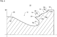
- FIG. 4 in particular relevant radii of the piston 10 are indicated.
- the piston 10 is a reciprocating piston of an internal combustion engine, in particular of a motor vehicle, for example a commercial vehicle.
- the commercial vehicle may be formed, for example, as a truck or a bus.
- the internal combustion engine is in particular a so-called HPDI (high pressure direct injection) diesel engine.
- HPDI high pressure direct injection
- Such an internal combustion engine is powered by gaseous fuel which is ignited by injection of diesel.
- a gaseous fuel for example liquefied natural gas (LNG)
- LNG liquefied natural gas
- the gaseous fuel is ignited in the combustion chambers by injected diesel fuel.
- the diesel fuel is injected as a high-pressure ignition jet directly into the combustion chamber.
- the diesel fuel can be injected at a pressure of up to 600 bar or more.
- the combustion of the gaseous fuel may take place in accordance with the diesel cycle.
- one and the same injector can be used, which can be designed as a two-fuel injector.
- the injector can be arranged centrally in the cylinder, and directed the diesel and gaseous fuel directed to a so-called beam splitter contour of the piston 10.
- the piston 10 is arranged in a cylinder (not shown) of the internal combustion engine and translationally movable relative to a cylinder wall of the cylinder.
- the internal combustion engine has a plurality of cylinders each having a piston 10.
- the internal combustion engine also includes a crankshaft which is rotatably mounted on a crankcase about an axis of rotation relative to the crankcase.
- the piston 10 is pivotally connected via a connecting rod with the crankshaft, so that the translational movements of Pistons 10 are converted in the cylinder in a rotational movement of the crankshaft about its axis of rotation. In the translational upward and downward movements of the piston 10, this can be supported on the cylinder wall.
- the piston 10 has a piston recess 12, a plurality of piston steps 14, 16 and a piston crown surface 18.
- the plurality of piston stages advantageously comprise a radially inner piston stage 14 and a radially outer piston stage 16.
- the piston 10 may be rotationally symmetrical about a central axis M.
- the piston recess 12 is formed as a so-called Omega trough.
- the omega trough has in cross-section substantially the shape of the Greek lowercase letter “omega” ( ⁇ ).
- the piston recess 12 has a central elevation 20.
- the central elevation 20 is shaped as a truncated cone. However, it is also possible, for example, that the central elevation 20 is shaped as a cone point.
- a top surface of the truncated cone shape of the central protrusion 20 is recessed in an axial direction of the center axis M by a height H1 from the piston crown surface 18.
- the top surface of the truncated cone shape of the central elevation 20 merges with a radius R1 in a lateral surface of the truncated cone shape of the central elevation 20. It is, for example, also possible that a conical surface section merges into a conical tip section of the central elevation with the radius R1 and / or the tip of the conical shape is rounded off with the radius R1.
- the piston recess 12 has an undercut region 22.
- the undercut region 22 then extends in a radial direction away from the central axis M, following the central elevation 20.
- the undercut region 22 is formed in an annular manner around the central axis M.
- the undercut region 22 can be provided with a radius R2.
- the beam splitter contour 24 is used in particular for splitting the injected diesel fuel ignition jets. Specifically, the diesel fuel jets are directed to the beam splitter contour 24.
- the beam splitter contour 24 divides the firing beams into a first partial flow and a second partial flow. The first partial flow is deflected along the undercut region 22 in a direction to the central axis M. The second partial flow is directed along the piston stages 14 and 16.
- the beam splitter contour 24 is formed as a radial projection.
- the radial projection is directed in a direction to the central axis.
- the beam splitter contour 24 projects beyond the undercut region 22 in a direction to the central axis M.
- the beam splitter contour 24 is formed annularly around the central axis M.
- the beam splitter contour 24 merges into the radially inner piston stage 14.
- the beam splitter contour 24 defines an inner diameter D1 at a radially innermost point of the beam splitter contour.
- the beam splitter contour 24 is provided with a radius R3.
- the radially inner piston stage 14 is annularly formed circumferentially about the central axis M.
- the radially inner piston stage 14 has a stepped bottom 26, a transition region 28 and a step wall 30.
- the stepped bottom 26 merges in a radial direction to the central axis M in the beam splitting contour 24.
- the transition region 28 connects the step bottom 26 and the step wall 30.
- the step wall 30 is in a radial direction away from the central axis M in the radially outer piston stage 16 via.
- step bottom 26 is inclined to a first plane which perpendicularly intersects the central axis M.
- the step bottom 26 may include an angle ⁇ with the first plane.
- step wall 30 is inclined to the center axis M.
- the step wall 30 may include an angle ⁇ with the central axis M.
- the stepped bottom 26 and the step wall 30 can merge into one another via the transition region 28 at an obtuse angle (an angle greater than 90 ° and less than 180 °).
- FIG. 3 It is shown that the radially inner piston stage 14, in particular at a transition between the stepped bottom 26 and the transition region 28 (see FIG. 1 ), an inner diameter D2 defined. In FIG. 3 is also shown that the radially inner piston stage 14, in particular at a transition between the stepped bottom 26 and the transition region 28 (see FIG. 1 ), along the central axis M with a height H2 axially recessed with respect to the piston crown surface 18 is formed.
- transition region 28 can be designed with a radius R4.
- the radially outer piston step 16 is annularly formed around the central axis M.
- the radially outer piston stage 16 has a stepped bottom 32, a transition region 34 and a step wall 36.
- the stepped bottom 32 merges in a radial direction to the central axis M in the step wall 30 of the radially inner piston stage 14.
- the transition region 34 connects the step bottom 32 and the step wall 36.
- the step wall 36 is in a radial direction away from the central axis M in the piston crown surface 18 via.
- the stepped bottom 32 is inclined to a second plane that perpendicularly intersects the central axis M.
- the step bottom 32 may include an angle ⁇ with the second plane.
- the step wall 36 may extend parallel to the central axis M.
- the stepped bottom 32 and the step wall 36 can merge into one another via the transition region 34 at an obtuse angle (an angle greater than 90 ° and less than 180 °).
- FIG. 3 It is shown that the radially outer piston step 16, in particular at a transition between the step wall 36 and the piston crown surface 18 (a radially outermost point of the radially outer piston step 16) define an inner diameter D3.
- step wall 30 of the radially inner piston stage 14 merges with a radius R5 in the stepped bottom 32 of the radially outer piston stage 16.
- transition region 34 can be designed with a radius R6.
- step wall 36 of the radially outer piston stage 16 can pass with a radius R7 in the piston crown surface 18.
- the piston crown surface 18 is provided in an annular manner around the central axis M.
- the piston crown surface 18 is flat or planar.
- the piston crown surface 18 merges into a lateral surface of the piston 10 on a radial outer side.
- a so-called squish flow (squish flow) is generated during a movement of the piston 10 to the top dead center, which is directed radially inwards to the central axis M.
- FIG. 5 are exemplary ranges of values, preferred ranges of values and particularly preferred value ranges for the angles ⁇ , ⁇ , ⁇ , ⁇ , the heights H0 to H3, the diameters D0 to D3 and the radii R1 to R7 indicated.
- the parameters D1 inner diameter at the beam splitter contour 24
- R3 radius of the beam splitter contour 24
- H1 height of the recess of the beam splitter contour 24
- the turbulence generation takes place for the first partial flow over the approximately 180 ° deflection in the undercut region 22 of the piston recess 12 by means of the radius R2 and the angle ⁇ .
- the turbulence generation takes place for the second partial flow via the flow separation edges realized by the piston stages 14, 16.
- the shape of the stall edges is given by the parameters ⁇ (angle of the inclined step bottom 26), ⁇ (angle of the inclined step wall 30), ⁇ (angle of the inclined step bottom 32), R4 (radius of the transition region 28), R5 (radius between the piston steps 14 , 16).
- a swirling combustion method is used in which the air intake passages of the cylinder are formed so that the intake air is introduced into the cylinder with a twist around the vertical axis of the cylinder (corresponding to the center axis M).
- the combined parameter groups (D1, R3 and H1, ⁇ and R2, ⁇ , ⁇ , ⁇ , R4 and R5), individually and in combination, allow the fuel and air to mix particularly well and homogeneously.
- a lean burning process can be used.
- the available air is effectively utilized by the combustion process and, in particular, there are little or no problems with local air deficiency zones leading to incomplete combustion of the fuel.
- the parameters ⁇ angle of the inclined step bottom 32
- R6 radius of the transition region 34
- H3 height of the recess of the radially outer piston step 16
- the parameters ⁇ , R6 and H3 indicate the area of the piston 10 which is farthest from the center of the piston 10 and the center axis M, respectively. In this area, particular care must be taken to maximize the conversion of the fuel so that no unburned hydrocarbons remain.
- the parameters R4 (radius of the transition region 28), R5 (radius of the transition between the piston stages 14, 16), ⁇ (angle of the inclined step wall 30) and the difference of the heights H2-H3 (difference of the recesses of the piston stages 14, 16) have in combination a great influence on the formation of soot during the combustion process.
- Soot for example, occurs when under fuel-rich conditions the fuel is not completely burned. During combustion, the flame front becomes at the step wall 30th braked. This braking effect or wall effect must not be too large, as otherwise the combustion is adversely affected.
- the step wall 30 is needed to represent a new tear-off edge for the second partial flow.
- a suitable combination of the parameters R4, R5, ⁇ and H2-H3 causes a combustion of the fuel which is as low as possible.
- the ratios H2 / H0 (height of the recess of the piston stage 14 / maximum depth of the piston recess 12), D3 / D1 (inner diameter at the piston crown surface 18 / inner diameter at the beam splitter contour 24) and the parameter ⁇ (angle of the central elevation 20) have in combination great influence on fuel consumption and nitrogen oxide formation, which are in an opposite relationship ("tradeoff").
- the relationships and the angle ⁇ relate to a ratio of the piston recess 12 to the region above the piston recess 12, which is limited by the piston stages 14 and 16.
- a combustion rate and an air utilization can be set.
- a high burning rate leads to a high combustion efficiency but also to high nitrogen oxide emissions.
- the nitrogen oxide emissions occur especially in zones with temperature peaks. By contrast, a low burning rate leads to a lower combustion efficiency but also to lower nitrogen oxide emissions.
- a suitable combination of the ratios H2 / H0, D3 / D1 and the parameter ⁇ brings about a balance between the best possible combustion efficiency and the lowest possible nitrogen oxide emissions.
- the parameters ⁇ (angle of the inclined step bottom 32), R2 (radius of the undercut region 22), R1 (radius at the transition of the central elevation to the top surface and cone tip) and H1 (height of the depression of the central elevation 20) act in combination in particular the carbon monoxide and hydrocarbon emissions, the combustion time and the fuel / air ratio required for combustion.
- the parameters ⁇ , R2, R1 and H1 characterize the volume within the piston recess 20. This volume should preferably not be too large, otherwise zones may arise in which the fuel from the flame front is not or not completely reached and thus implemented. Such zones should instead be filled by piston material.
- a suitable combination of the parameters ⁇ , R2, R1 and H1 results in low carbon monoxide and hydrocarbon emissions, optimizes combustion time and allows a lean burning process.
- the invention is not limited to the preferred embodiments described above. Rather, a variety of variants and modifications is possible, which also make use of the idea of the invention and therefore fall within the scope of protection.
- the invention also claims protection of the subject matter and the features of the subclaims independently of the claims referred to.
- the features of independent claim 1 are independently disclosed.
- the features of the subclaims are also disclosed independently of all the features of independent claim 1 and, for example, independently of the features relating to the presence and / or the configuration of the piston recess, the piston crown surface and / or the plurality of piston stages of independent claim 1.
Applications Claiming Priority (1)
| Application Number | Priority Date | Filing Date | Title |
|---|---|---|---|
| DE102017127291.7A DE102017127291A1 (de) | 2017-11-20 | 2017-11-20 | Kolben, insbesondere für eine HPDI-Diesel-Gasbrennkraftmaschine |
Publications (2)
| Publication Number | Publication Date |
|---|---|
| EP3486447A1 true EP3486447A1 (fr) | 2019-05-22 |
| EP3486447B1 EP3486447B1 (fr) | 2021-11-03 |
Family
ID=63667710
Family Applications (1)
| Application Number | Title | Priority Date | Filing Date |
|---|---|---|---|
| EP18195591.5A Active EP3486447B1 (fr) | 2017-11-20 | 2018-09-20 | Piston, en particulier pour un moteur à combustion interne à gaz diesel hpdi |
Country Status (4)
| Country | Link |
|---|---|
| US (1) | US10890136B2 (fr) |
| EP (1) | EP3486447B1 (fr) |
| CN (1) | CN109931179B (fr) |
| DE (1) | DE102017127291A1 (fr) |
Families Citing this family (7)
| Publication number | Priority date | Publication date | Assignee | Title |
|---|---|---|---|---|
| JP2021011843A (ja) * | 2019-07-05 | 2021-02-04 | 三菱重工エンジン&ターボチャージャ株式会社 | 内燃機関のピストンおよび内燃機関 |
| DE102019006760A1 (de) * | 2019-09-27 | 2021-04-01 | Daimler Ag | Kolben für eine Hubkolbenmaschine, insbesondere eines Kraftfahrzeugs, sowie Hubkolbenmaschine für ein Kraftfahrzeug |
| JP2021181765A (ja) * | 2020-05-19 | 2021-11-25 | 株式会社小松製作所 | ディーゼルエンジン用のピストン及びディーゼルエンジン |
| DE102020208998A1 (de) * | 2020-07-17 | 2022-01-20 | Mahle International Gmbh | Kolben für eine Brennkraftmaschine |
| US11898488B2 (en) * | 2021-05-12 | 2024-02-13 | Caterpillar Inc. | Piston bowl geometry, cuff and top land interaction for reduced hydrocarbons, improved combustion efficiency, and piston temperature |
| CN115324767A (zh) * | 2022-10-13 | 2022-11-11 | 潍柴动力股份有限公司 | 活塞燃烧室及其设计方法、活塞及发动机 |
| CN116006347A (zh) * | 2023-03-28 | 2023-04-25 | 潍柴动力股份有限公司 | 一种活塞、发动机及车辆 |
Citations (5)
| Publication number | Priority date | Publication date | Assignee | Title |
|---|---|---|---|---|
| JP2004190573A (ja) * | 2002-12-11 | 2004-07-08 | Yanmar Co Ltd | エンジンの燃焼室 |
| US20050115537A1 (en) * | 2003-12-01 | 2005-06-02 | Zhengbai Liu | Combustion chamber |
| DE112008002527T5 (de) * | 2007-09-21 | 2010-08-12 | Denso Corp. | Dieselmotor |
| WO2014196423A1 (fr) * | 2013-06-06 | 2014-12-11 | 日野自動車株式会社 | Structure de chambre de combustion d'un moteur diesel à injection directe |
| DE102016116046A1 (de) * | 2015-08-28 | 2017-03-02 | Ks Kolbenschmidt Gmbh | Kolben mit niedriger Bauhöhe |
Family Cites Families (22)
| Publication number | Priority date | Publication date | Assignee | Title |
|---|---|---|---|---|
| JPH04103827A (ja) * | 1990-08-22 | 1992-04-06 | Nissan Motor Co Ltd | 直噴式ディーゼルエンジン |
| US7210448B2 (en) * | 2002-06-11 | 2007-05-01 | Cummins, Inc. | Internal combustion engine producing low emissions |
| US8276563B2 (en) * | 2002-06-28 | 2012-10-02 | Cummins, Inc. | Internal combustion engine piston |
| DE102005051740A1 (de) * | 2004-12-04 | 2006-06-08 | Daimlerchrysler Ag | Brennraum einer selbstzündenden Brennkraftmaschine |
| DE102006020642B4 (de) * | 2006-05-04 | 2019-05-23 | Daimler Ag | Verfahren zum Betrieb einer Brennkraftmaschine und Brennkraftmaschine für ein solches Verfahren |
| DE102009025404B4 (de) * | 2009-06-16 | 2018-01-25 | Mtu Friedrichshafen Gmbh | Kolben für ventilgesteuerte Hubkolben-Dieselbrennkraftmaschinen |
| DE102009032941A1 (de) * | 2009-07-14 | 2011-01-20 | Mahle International Gmbh | Mehrteiliger Kolben für einen Verbrennungsmotor und Verfahren zu seiner Herstellung |
| CN103814204B (zh) * | 2011-09-28 | 2016-10-12 | 三菱重工业株式会社 | 直喷式柴油机装置 |
| KR101745005B1 (ko) * | 2011-10-07 | 2017-06-09 | 현대자동차주식회사 | 디젤-가솔린 복합연료엔진 |
| DE102011119215B4 (de) * | 2011-11-23 | 2021-07-22 | Daimler Ag | Verbrennungsverfahren und Brennkraftmaschine |
| CA2826435C (fr) * | 2013-09-06 | 2016-01-05 | Westport Power Inc. | Systeme de combustion pour moteur a combustion interne a combustible gazeux |
| CN103696870B (zh) * | 2013-12-09 | 2016-03-16 | 潍柴动力股份有限公司 | 一种柴油机气缸活塞及应用该燃烧室的柴油机 |
| DE102013022040A1 (de) | 2013-12-20 | 2015-06-25 | Daimler Ag | Kolben für eine Hubkolben-Verbrennungskraftmaschine |
| FR3017421B1 (fr) * | 2014-02-10 | 2018-03-16 | IFP Energies Nouvelles | Moteur a combustion interne a injection de deux nappes de combustible a debit differencie et procede d'injection de combustible pour un tel moteur. |
| FR3018552B1 (fr) * | 2014-03-14 | 2019-07-05 | IFP Energies Nouvelles | Moteur a combustion a injection directe de combustible a allumage par compression comprenant des moyens de refroidissement du piston. |
| CN106414943B (zh) * | 2014-05-22 | 2019-10-18 | 日产自动车株式会社 | 柴油发动机的燃烧室构造 |
| DE102015012541A1 (de) | 2015-09-24 | 2016-04-14 | Daimler Ag | Kolben für einen Gasmotor sowie Gasmotor mit einem solchen Kolben |
| US20170145951A1 (en) * | 2015-11-19 | 2017-05-25 | Caterpillar Inc. | Textured Piston |
| US10184388B1 (en) * | 2015-11-30 | 2019-01-22 | Caterpillar Inc. | Engine piston |
| CN105909420A (zh) * | 2016-06-14 | 2016-08-31 | 广西玉柴机器股份有限公司 | 降低柴油机缸内碳烟的燃烧室 |
| US10113503B2 (en) * | 2016-10-11 | 2018-10-30 | Caterpillar Inc. | Combustion bowl of a piston for an engine |
| US10731600B2 (en) * | 2017-11-07 | 2020-08-04 | Deere & Company | Piston with soot reducing piston bowl |
-
2017
- 2017-11-20 DE DE102017127291.7A patent/DE102017127291A1/de not_active Withdrawn
-
2018
- 2018-09-20 EP EP18195591.5A patent/EP3486447B1/fr active Active
- 2018-11-14 CN CN201811351977.2A patent/CN109931179B/zh active Active
- 2018-11-20 US US16/196,210 patent/US10890136B2/en active Active
Patent Citations (5)
| Publication number | Priority date | Publication date | Assignee | Title |
|---|---|---|---|---|
| JP2004190573A (ja) * | 2002-12-11 | 2004-07-08 | Yanmar Co Ltd | エンジンの燃焼室 |
| US20050115537A1 (en) * | 2003-12-01 | 2005-06-02 | Zhengbai Liu | Combustion chamber |
| DE112008002527T5 (de) * | 2007-09-21 | 2010-08-12 | Denso Corp. | Dieselmotor |
| WO2014196423A1 (fr) * | 2013-06-06 | 2014-12-11 | 日野自動車株式会社 | Structure de chambre de combustion d'un moteur diesel à injection directe |
| DE102016116046A1 (de) * | 2015-08-28 | 2017-03-02 | Ks Kolbenschmidt Gmbh | Kolben mit niedriger Bauhöhe |
Also Published As
| Publication number | Publication date |
|---|---|
| DE102017127291A1 (de) | 2019-05-23 |
| BR102018070490A2 (pt) | 2019-09-17 |
| RU2018136152A3 (fr) | 2022-02-11 |
| EP3486447B1 (fr) | 2021-11-03 |
| US20190153976A1 (en) | 2019-05-23 |
| CN109931179B (zh) | 2023-01-03 |
| US10890136B2 (en) | 2021-01-12 |
| RU2018136152A (ru) | 2020-04-13 |
| CN109931179A (zh) | 2019-06-25 |
Similar Documents
| Publication | Publication Date | Title |
|---|---|---|
| EP3486447B1 (fr) | Piston, en particulier pour un moteur à combustion interne à gaz diesel hpdi | |
| DE10392141B4 (de) | Kolben für Verbrennungsmotor | |
| DE112008000856T5 (de) | Verbrennungsmotor und Betriebsverfahren dafür | |
| DE102011119215A1 (de) | Verbrennungsverfahren und Brennkraftmaschine | |
| DE102015012541A1 (de) | Kolben für einen Gasmotor sowie Gasmotor mit einem solchen Kolben | |
| DE102015100361B4 (de) | Verbrennungssystem einschließlich Kolbenboden und Kraftstoffinjektor | |
| DE10393905B4 (de) | Verfahren zum Betreiben einer direkteinspritzenden Diesel-Brennkraftmaschine | |
| AT522462A4 (de) | Brennkraftmaschine mit einem zylinderkopf | |
| DE2901211A1 (de) | Verfahren zum betrieb einer luftverdichtenden, selbstzuendenden brennkraftmaschine fuer fluessige brennstoffe | |
| DE102013022040A1 (de) | Kolben für eine Hubkolben-Verbrennungskraftmaschine | |
| AT407425B (de) | Brennkraftmaschine mit fremdzündung | |
| DE102005055367A1 (de) | Dieselbrennkraftmaschine | |
| WO2006048134A1 (fr) | Moteur a combustion interne a injection directe | |
| EP2615296A1 (fr) | Procédé et dispositif d'injection de carburant dans une chambre de combustion d'un moteur à combustion | |
| AT514638A2 (de) | Kolben einer Brennkraftmaschine | |
| DE102018006635B4 (de) | Verfahren zum Betreiben einer Verbrennungskraftmaschine für ein Kraftfahrzeug, sowie Verbrennungskraftmaschine für ein Kraftfahrzeug | |
| DE102014002625A1 (de) | Kolben für eine Hubkolben-Verbrennungskraftmaschine sowie Zylinderkopf für eine Hubkolben-Verbrennungskraftmaschine | |
| EP1387952A1 (fr) | Systeme d'injection de carburant | |
| DE102015002131B4 (de) | Anordnung mit einer Injektorvorrichtung für das Ausdüsen von Brenngas und Flüssigkraftstoff | |
| WO2012143075A1 (fr) | Piston pour moteur à combustion interne à piston alternatif | |
| DE102012002897B4 (de) | Verbrennungskraftmaschine, insbesondere für einen Kraftwagen | |
| EP2060737A1 (fr) | Agencement de cylindre pour un moteur à combustion interne à piston élévateur tout comme moteur à combustion interne à piston élévateur | |
| DE102018005113A1 (de) | Muldenkolben für eine Verbrennungskraftmaschine | |
| DE102005044503A1 (de) | Brennkraftmaschine in Hubkolbenbauweise | |
| DE102014010714A1 (de) | Brennverfahren |
Legal Events
| Date | Code | Title | Description |
|---|---|---|---|
| PUAI | Public reference made under article 153(3) epc to a published international application that has entered the european phase |
Free format text: ORIGINAL CODE: 0009012 |
|
| STAA | Information on the status of an ep patent application or granted ep patent |
Free format text: STATUS: THE APPLICATION HAS BEEN PUBLISHED |
|
| AK | Designated contracting states |
Kind code of ref document: A1 Designated state(s): AL AT BE BG CH CY CZ DE DK EE ES FI FR GB GR HR HU IE IS IT LI LT LU LV MC MK MT NL NO PL PT RO RS SE SI SK SM TR |
|
| AX | Request for extension of the european patent |
Extension state: BA ME |
|
| RAP1 | Party data changed (applicant data changed or rights of an application transferred) |
Owner name: MAN TRUCK & BUS SE |
|
| STAA | Information on the status of an ep patent application or granted ep patent |
Free format text: STATUS: REQUEST FOR EXAMINATION WAS MADE |
|
| 17P | Request for examination filed |
Effective date: 20191121 |
|
| RBV | Designated contracting states (corrected) |
Designated state(s): AL AT BE BG CH CY CZ DE DK EE ES FI FR GB GR HR HU IE IS IT LI LT LU LV MC MK MT NL NO PL PT RO RS SE SI SK SM TR |
|
| STAA | Information on the status of an ep patent application or granted ep patent |
Free format text: STATUS: EXAMINATION IS IN PROGRESS |
|
| 17Q | First examination report despatched |
Effective date: 20200131 |
|
| STAA | Information on the status of an ep patent application or granted ep patent |
Free format text: STATUS: EXAMINATION IS IN PROGRESS |
|
| GRAP | Despatch of communication of intention to grant a patent |
Free format text: ORIGINAL CODE: EPIDOSNIGR1 |
|
| STAA | Information on the status of an ep patent application or granted ep patent |
Free format text: STATUS: GRANT OF PATENT IS INTENDED |
|
| INTG | Intention to grant announced |
Effective date: 20210601 |
|
| GRAS | Grant fee paid |
Free format text: ORIGINAL CODE: EPIDOSNIGR3 |
|
| GRAA | (expected) grant |
Free format text: ORIGINAL CODE: 0009210 |
|
| STAA | Information on the status of an ep patent application or granted ep patent |
Free format text: STATUS: THE PATENT HAS BEEN GRANTED |
|
| AK | Designated contracting states |
Kind code of ref document: B1 Designated state(s): AL AT BE BG CH CY CZ DE DK EE ES FI FR GB GR HR HU IE IS IT LI LT LU LV MC MK MT NL NO PL PT RO RS SE SI SK SM TR |
|
| REG | Reference to a national code |
Ref country code: GB Ref legal event code: FG4D Free format text: NOT ENGLISH |
|
| REG | Reference to a national code |
Ref country code: AT Ref legal event code: REF Ref document number: 1444134 Country of ref document: AT Kind code of ref document: T Effective date: 20211115 Ref country code: CH Ref legal event code: EP |
|
| REG | Reference to a national code |
Ref country code: IE Ref legal event code: FG4D Free format text: LANGUAGE OF EP DOCUMENT: GERMAN |
|
| REG | Reference to a national code |
Ref country code: DE Ref legal event code: R096 Ref document number: 502018007665 Country of ref document: DE |
|
| REG | Reference to a national code |
Ref country code: SE Ref legal event code: TRGR |
|
| REG | Reference to a national code |
Ref country code: NL Ref legal event code: FP |
|
| REG | Reference to a national code |
Ref country code: LT Ref legal event code: MG9D |
|
| PG25 | Lapsed in a contracting state [announced via postgrant information from national office to epo] |
Ref country code: RS Free format text: LAPSE BECAUSE OF FAILURE TO SUBMIT A TRANSLATION OF THE DESCRIPTION OR TO PAY THE FEE WITHIN THE PRESCRIBED TIME-LIMIT Effective date: 20211103 Ref country code: LT Free format text: LAPSE BECAUSE OF FAILURE TO SUBMIT A TRANSLATION OF THE DESCRIPTION OR TO PAY THE FEE WITHIN THE PRESCRIBED TIME-LIMIT Effective date: 20211103 Ref country code: FI Free format text: LAPSE BECAUSE OF FAILURE TO SUBMIT A TRANSLATION OF THE DESCRIPTION OR TO PAY THE FEE WITHIN THE PRESCRIBED TIME-LIMIT Effective date: 20211103 Ref country code: BG Free format text: LAPSE BECAUSE OF FAILURE TO SUBMIT A TRANSLATION OF THE DESCRIPTION OR TO PAY THE FEE WITHIN THE PRESCRIBED TIME-LIMIT Effective date: 20220203 |
|
| PG25 | Lapsed in a contracting state [announced via postgrant information from national office to epo] |
Ref country code: IS Free format text: LAPSE BECAUSE OF FAILURE TO SUBMIT A TRANSLATION OF THE DESCRIPTION OR TO PAY THE FEE WITHIN THE PRESCRIBED TIME-LIMIT Effective date: 20220303 Ref country code: PT Free format text: LAPSE BECAUSE OF FAILURE TO SUBMIT A TRANSLATION OF THE DESCRIPTION OR TO PAY THE FEE WITHIN THE PRESCRIBED TIME-LIMIT Effective date: 20220303 Ref country code: PL Free format text: LAPSE BECAUSE OF FAILURE TO SUBMIT A TRANSLATION OF THE DESCRIPTION OR TO PAY THE FEE WITHIN THE PRESCRIBED TIME-LIMIT Effective date: 20211103 Ref country code: NO Free format text: LAPSE BECAUSE OF FAILURE TO SUBMIT A TRANSLATION OF THE DESCRIPTION OR TO PAY THE FEE WITHIN THE PRESCRIBED TIME-LIMIT Effective date: 20220203 Ref country code: LV Free format text: LAPSE BECAUSE OF FAILURE TO SUBMIT A TRANSLATION OF THE DESCRIPTION OR TO PAY THE FEE WITHIN THE PRESCRIBED TIME-LIMIT Effective date: 20211103 Ref country code: HR Free format text: LAPSE BECAUSE OF FAILURE TO SUBMIT A TRANSLATION OF THE DESCRIPTION OR TO PAY THE FEE WITHIN THE PRESCRIBED TIME-LIMIT Effective date: 20211103 Ref country code: GR Free format text: LAPSE BECAUSE OF FAILURE TO SUBMIT A TRANSLATION OF THE DESCRIPTION OR TO PAY THE FEE WITHIN THE PRESCRIBED TIME-LIMIT Effective date: 20220204 Ref country code: ES Free format text: LAPSE BECAUSE OF FAILURE TO SUBMIT A TRANSLATION OF THE DESCRIPTION OR TO PAY THE FEE WITHIN THE PRESCRIBED TIME-LIMIT Effective date: 20211103 |
|
| PG25 | Lapsed in a contracting state [announced via postgrant information from national office to epo] |
Ref country code: SM Free format text: LAPSE BECAUSE OF FAILURE TO SUBMIT A TRANSLATION OF THE DESCRIPTION OR TO PAY THE FEE WITHIN THE PRESCRIBED TIME-LIMIT Effective date: 20211103 Ref country code: SK Free format text: LAPSE BECAUSE OF FAILURE TO SUBMIT A TRANSLATION OF THE DESCRIPTION OR TO PAY THE FEE WITHIN THE PRESCRIBED TIME-LIMIT Effective date: 20211103 Ref country code: RO Free format text: LAPSE BECAUSE OF FAILURE TO SUBMIT A TRANSLATION OF THE DESCRIPTION OR TO PAY THE FEE WITHIN THE PRESCRIBED TIME-LIMIT Effective date: 20211103 Ref country code: EE Free format text: LAPSE BECAUSE OF FAILURE TO SUBMIT A TRANSLATION OF THE DESCRIPTION OR TO PAY THE FEE WITHIN THE PRESCRIBED TIME-LIMIT Effective date: 20211103 Ref country code: DK Free format text: LAPSE BECAUSE OF FAILURE TO SUBMIT A TRANSLATION OF THE DESCRIPTION OR TO PAY THE FEE WITHIN THE PRESCRIBED TIME-LIMIT Effective date: 20211103 Ref country code: CZ Free format text: LAPSE BECAUSE OF FAILURE TO SUBMIT A TRANSLATION OF THE DESCRIPTION OR TO PAY THE FEE WITHIN THE PRESCRIBED TIME-LIMIT Effective date: 20211103 |
|
| REG | Reference to a national code |
Ref country code: DE Ref legal event code: R097 Ref document number: 502018007665 Country of ref document: DE |
|
| PLBE | No opposition filed within time limit |
Free format text: ORIGINAL CODE: 0009261 |
|
| STAA | Information on the status of an ep patent application or granted ep patent |
Free format text: STATUS: NO OPPOSITION FILED WITHIN TIME LIMIT |
|
| 26N | No opposition filed |
Effective date: 20220804 |
|
| PG25 | Lapsed in a contracting state [announced via postgrant information from national office to epo] |
Ref country code: AL Free format text: LAPSE BECAUSE OF FAILURE TO SUBMIT A TRANSLATION OF THE DESCRIPTION OR TO PAY THE FEE WITHIN THE PRESCRIBED TIME-LIMIT Effective date: 20211103 |
|
| PG25 | Lapsed in a contracting state [announced via postgrant information from national office to epo] |
Ref country code: SI Free format text: LAPSE BECAUSE OF FAILURE TO SUBMIT A TRANSLATION OF THE DESCRIPTION OR TO PAY THE FEE WITHIN THE PRESCRIBED TIME-LIMIT Effective date: 20211103 |
|
| PG25 | Lapsed in a contracting state [announced via postgrant information from national office to epo] |
Ref country code: MC Free format text: LAPSE BECAUSE OF FAILURE TO SUBMIT A TRANSLATION OF THE DESCRIPTION OR TO PAY THE FEE WITHIN THE PRESCRIBED TIME-LIMIT Effective date: 20211103 |
|
| REG | Reference to a national code |
Ref country code: CH Ref legal event code: PL |
|
| REG | Reference to a national code |
Ref country code: BE Ref legal event code: MM Effective date: 20220930 |
|
| PG25 | Lapsed in a contracting state [announced via postgrant information from national office to epo] |
Ref country code: LU Free format text: LAPSE BECAUSE OF NON-PAYMENT OF DUE FEES Effective date: 20220920 |
|
| PG25 | Lapsed in a contracting state [announced via postgrant information from national office to epo] |
Ref country code: LI Free format text: LAPSE BECAUSE OF NON-PAYMENT OF DUE FEES Effective date: 20220930 Ref country code: IE Free format text: LAPSE BECAUSE OF NON-PAYMENT OF DUE FEES Effective date: 20220920 Ref country code: CH Free format text: LAPSE BECAUSE OF NON-PAYMENT OF DUE FEES Effective date: 20220930 |
|
| PG25 | Lapsed in a contracting state [announced via postgrant information from national office to epo] |
Ref country code: BE Free format text: LAPSE BECAUSE OF NON-PAYMENT OF DUE FEES Effective date: 20220930 |
|
| PGFP | Annual fee paid to national office [announced via postgrant information from national office to epo] |
Ref country code: NL Payment date: 20230926 Year of fee payment: 6 Ref country code: IT Payment date: 20230920 Year of fee payment: 6 Ref country code: GB Payment date: 20230926 Year of fee payment: 6 |
|
| PGFP | Annual fee paid to national office [announced via postgrant information from national office to epo] |
Ref country code: SE Payment date: 20230926 Year of fee payment: 6 Ref country code: FR Payment date: 20230926 Year of fee payment: 6 Ref country code: DE Payment date: 20230928 Year of fee payment: 6 |
|
| PG25 | Lapsed in a contracting state [announced via postgrant information from national office to epo] |
Ref country code: HU Free format text: LAPSE BECAUSE OF FAILURE TO SUBMIT A TRANSLATION OF THE DESCRIPTION OR TO PAY THE FEE WITHIN THE PRESCRIBED TIME-LIMIT; INVALID AB INITIO Effective date: 20180920 |
|
| PG25 | Lapsed in a contracting state [announced via postgrant information from national office to epo] |
Ref country code: CY Free format text: LAPSE BECAUSE OF FAILURE TO SUBMIT A TRANSLATION OF THE DESCRIPTION OR TO PAY THE FEE WITHIN THE PRESCRIBED TIME-LIMIT Effective date: 20211103 |