EP3486366A1 - Wäschebehandlungsvorrichtung mit einer benutzerschnittstelle innerhalb einer türanordnung - Google Patents
Wäschebehandlungsvorrichtung mit einer benutzerschnittstelle innerhalb einer türanordnung Download PDFInfo
- Publication number
- EP3486366A1 EP3486366A1 EP18205788.5A EP18205788A EP3486366A1 EP 3486366 A1 EP3486366 A1 EP 3486366A1 EP 18205788 A EP18205788 A EP 18205788A EP 3486366 A1 EP3486366 A1 EP 3486366A1
- Authority
- EP
- European Patent Office
- Prior art keywords
- door
- laundry treating
- treating appliance
- door assembly
- trim element
- Prior art date
- Legal status (The legal status is an assumption and is not a legal conclusion. Google has not performed a legal analysis and makes no representation as to the accuracy of the status listed.)
- Granted
Links
Images











Classifications
-
- D—TEXTILES; PAPER
- D06—TREATMENT OF TEXTILES OR THE LIKE; LAUNDERING; FLEXIBLE MATERIALS NOT OTHERWISE PROVIDED FOR
- D06F—LAUNDERING, DRYING, IRONING, PRESSING OR FOLDING TEXTILE ARTICLES
- D06F39/00—Details of washing machines not specific to a single type of machines covered by groups D06F9/00 - D06F27/00
- D06F39/12—Casings; Tubs
- D06F39/14—Doors or covers; Securing means therefor
-
- D—TEXTILES; PAPER
- D06—TREATMENT OF TEXTILES OR THE LIKE; LAUNDERING; FLEXIBLE MATERIALS NOT OTHERWISE PROVIDED FOR
- D06F—LAUNDERING, DRYING, IRONING, PRESSING OR FOLDING TEXTILE ARTICLES
- D06F33/00—Control of operations performed in washing machines or washer-dryers
-
- D—TEXTILES; PAPER
- D06—TREATMENT OF TEXTILES OR THE LIKE; LAUNDERING; FLEXIBLE MATERIALS NOT OTHERWISE PROVIDED FOR
- D06F—LAUNDERING, DRYING, IRONING, PRESSING OR FOLDING TEXTILE ARTICLES
- D06F2101/00—User input for the control of domestic laundry washing machines, washer-dryers or laundry dryers
-
- D—TEXTILES; PAPER
- D06—TREATMENT OF TEXTILES OR THE LIKE; LAUNDERING; FLEXIBLE MATERIALS NOT OTHERWISE PROVIDED FOR
- D06F—LAUNDERING, DRYING, IRONING, PRESSING OR FOLDING TEXTILE ARTICLES
- D06F2105/00—Systems or parameters controlled or affected by the control systems of washing machines, washer-dryers or laundry dryers
- D06F2105/58—Indications or alarms to the control system or to the user
- D06F2105/60—Audible signals
-
- D—TEXTILES; PAPER
- D06—TREATMENT OF TEXTILES OR THE LIKE; LAUNDERING; FLEXIBLE MATERIALS NOT OTHERWISE PROVIDED FOR
- D06F—LAUNDERING, DRYING, IRONING, PRESSING OR FOLDING TEXTILE ARTICLES
- D06F34/00—Details of control systems for washing machines, washer-dryers or laundry dryers
- D06F34/28—Arrangements for program selection, e.g. control panels therefor; Arrangements for indicating program parameters, e.g. the selected program or its progress
Definitions
- Laundry treating appliances such as clothes washers, clothes dryers, refreshers, and non-aqueous systems, can have a configuration based on a rotating laundry basket that defines a treating chamber in which laundry items are placed for treating.
- the laundry treating appliance can include a cabinet including a panel with an access opening through which clothes are loaded and unloaded into the treating chamber.
- a door assembly can be movably mounted to the cabinet to selectively open and close the access opening to the treating chamber.
- the door assembly can include multiple door pieces to support various parts of the door assembly, such as a transparent or partially transparent viewing window, a hinge assembly, and a user interface for the laundry treating appliance.
- illustrative embodiments in accordance with the present disclosure relate to a laundry treating appliance comprising a cabinet defining an interior, a drum located within the interior and defining a treating chamber, and a door assembly coupled to the cabinet to selectively open and close the treating chamber and at least partially defining the treating chamber when the door assembly is in a closed condition.
- the door assembly comprises an intermediate door having front and rear surfaces, defining an opening, and having a plurality of receiving openings forming a first part of a heat stake connection, a user interface mounted to the intermediate door, a door window mounted to the intermediate frame and overlying the opening, a door cover adjacent the front surface of the intermediate door and overlying the user interface, a rear door adjacent the rear surface of the intermediate door, and a trim element provided about at least a periphery of the intermediate door and having a plurality of posts, the posts configured to be received within the receiving openings and forming a second part of the heat stake connection, the posts and receiving openings collectively forming the heat stake connection to create a plurality of caps to secure the trim element to the intermediate door.
- illustrative embodiments in accordance with the present disclosure relate to a laundry treating appliance comprising a cabinet defining an interior, a drum located within the interior and defining a treating chamber, and a door assembly coupled to the cabinet to selectively open and close the treating chamber and at least partially defining the treating chamber when the door assembly is in a closed condition.
- the door assembly comprises an intermediate door having front and rear surfaces and defining an opening, a user interface mounted to the intermediate door, a door window mounted to the intermediate frame and overlying the opening, a door cover adjacent the front surface of the intermediate door and overlying the user interface, a rear door adjacent the rear surface of the intermediate door, a trim element provided about at least a periphery of the intermediate door, and a heat stake connection comprising a plurality of posts on one of the intermediate door or the trim element and a plurality of receiving on the other of the intermediate door or the trim element, the posts configured to be received within the receiving openings and thermally deformed to create a plurality of caps to secure the trim element to the intermediate door.
- Door assemblies for laundry treating appliances can include a variety of features and components, including, but not limited to, a transparent viewing window area, structures for preventing the passage of liquid from the interior of the laundry treating appliance to the exterior of the laundry treating appliance, and even a user interface and display area.
- a viewing window for the user interface and display area can be accompanied by screen decoration to cover the associated electronics and provide a clean aesthetic to the user.
- the structure of the door cover can be altered in the area of the user interface to provide a flat, angled surface for the user interface that allows for high acuity of a touch screen.
- Speaker openings can also be provided in the door assembly for improved transmission of auditory cues to a user.
- the door assembly can include additional features and structures to ensure that the user interface can operate properly within the door assembly and that electronic components are protected from liquid within the laundry treating appliance.
- the door assembly can include structures to keep liquid from contacting electronic components of the user interface, such as gaskets and water diverting channels, and structures to ensure that sensitivity of the user interface and its associated electronics and functions are optimized for ease of function and operability.
- Such a door assembly can comprise multiple components that together form the door assembly.
- the use of multiple components to form the door assembly can require additional consideration to ensure that the door assembly is assembled in an efficient manner that allows for a durable door assembly and sturdy connections between the multiple components of the door assembly.
- the use of specialized fasteners, hooks, and heat staking can improve assembling of the components of the door assembly. Snaps for a viewing window can serve not only to secure the window piece, but to center it within the door assembly.
- the door assembly of the present disclosure has applicability in a variety of laundry treating appliances, including, but not limited to, both laundry washing appliances and laundry drying appliances. While certain aspects of the door assembly can be the same regardless of whether the door assembly is used in the context of a laundry washing appliance or a laundry drying appliance, it will also be understood that other aspects of the door assembly can be different depending on whether the door assembly is used in the context of a laundry washing appliance or a laundry drying appliance. By way of non-limiting example, the features of the viewing window or the structures for water protection or transmission of sound can differ depending on the context in which the door assembly is intended to be used.
- a laundry treating appliance 10 can be any laundry treating appliance 10 that performs a cycle of operation to clean or otherwise treat laundry items placed therein.
- the laundry treating appliance 10 is illustrated herein as a horizontal axis, front-load laundry treating appliance 10, such as, but not limited to, a washing machine or a laundry dryer.
- front-load laundry treating appliance 10 such as, but not limited to, a washing machine or a laundry dryer.
- the embodiments of the present disclosure can have applicability in other horizontal axis laundry treating appliances, non-limiting examples of which include a combination washing machine or dryer, a refreshing/revitalizing machine, an extractor, or a non-aqueous washing apparatus, or also a horizontal axis laundry treating appliance that is top-loading.
- the embodiments can have applicability in vertical axis laundry treating appliances and other appliances having a door, whether it be hinged, slidable, or otherwise attached to a cabinet, with access to a treating chamber.
- the laundry treating appliance shares many feature of a conventional automated clothes washer and/or dryer, which will not be described in detail herein except as necessary for a complete understanding of the exemplary embodiments in accordance with the present disclosure.
- the laundry treating appliance 10 can include a structural support assembly comprising a cabinet 12 defining a housing within which a laundry holding assembly resides.
- the cabinet 12 can be a housing having a chassis and/or a frame, defining an interior, enclosing components typically found in a conventional washing machine or drying machine. Conventional washing machine or drying machine components are not described in detail, but are described briefly as needed to provide an illustrative environment to support a complete understanding of aspects of the present disclosure.
- the laundry holding assembly may include a rotatable drum 16 supported within the cabinet 12 by a suitable suspension assembly and defining at least a portion of a laundry treating chamber 18 for receiving the laundry and which rotates about a rotational axis, which for convenience, but not limitation, happens to be illustrated as a generally horizontal axis.
- the drum 16 is configured to receive a laundry load comprising articles for treatment, including, but not limited to, a hat, a scarf, a glove, a sweater, a blouse, a shirt, a pair of shorts, a dress, a sock, and a pair of pants, a shoe, an undergarment, and a jacket.
- An access opening 22 in a front panel 14 of the cabinet 12 provides access to the laundry treating chamber 18.
- the laundry holding assembly may further include a door assembly 100 which can be movably mounted to the cabinet 12 to selectively close the access opening 22 to the treating chamber 18.
- the door assembly 100 can have a handle 62 for pivotally opening the door about a hinge assembly 64.
- the door assembly 100 can further include an integrated user interface 30 comprising a plurality of buttons 36, which can be touch sensitive buttons 36, a display module 34, which can be a touch sensitive liquid crystal display module 34, and a user interface controller 32.
- the door assembly 100 comprises an outer door assembly 140, the display module 34, and an inner door assembly 160, 180 that, when coupled together, form the door assembly 100.
- FIG. 1 shows the door assembly 100 in a closed condition
- FIG. 2 shows the door assembly 100 in an open condition.
- FIG. 3 illustrates an exploded view of an exemplary embodiment of the door assembly 100 including the outer door assembly 140 and the inner door assembly 160, and that includes a portion of the user interface 30.
- a door cover 102 provides the front surface for the door assembly 100.
- the door cover 102 is formed of a plastic material. However, it will be understood that glass, composite, or other suitable material can be used to form the door cover 102.
- the door cover 102 can be partially transparent to allow a user to view the treating chamber 18, or can be entirely transparent across the entirety of the door cover 102.
- the door cover 102 can also include the plurality of buttons 36.
- An intermediate door 104 is also provided, and can be positioned to the rear of the door cover 102.
- the intermediate door 104 can be formed of plastic, metal, or any suitable composition.
- the intermediate door 104 includes a central opening 114 and a display opening 116.
- the central opening 114 can be configured to line up with a transparent portion of the door cover 102 to allow a user to view the treating chamber 18 through the door assembly 100, even when the door assembly 100 is in the closed condition.
- the display opening 116 can also be configured to line up with a second transparent portion of the door cover 102, to allow a user to view the user interface 30.
- the door cover 102 can have separate transparent portions corresponding to the central opening 114 and the display opening 116 of the intermediate door 104, or the entire door cover 102 can be transparent. It will also be understood that the transparent portion or portions of the door cover 102 are not limited to being the size and shape of the central opening 114 or the display opening 116, but could also be larger or smaller than the central opening 114
- a trim element illustrated herein as a peripheral trim ring 106, is provided and can be configured to be coupled with and to surround the peripheral edges of at least the door cover 102 and the intermediate door 104.
- the peripheral trim ring 106 can be formed of plastic, metal, or any suitable composition.
- a touch film 108 is provided.
- the touch film 108 is adhesively bonded to a rear surface 118 of the door cover 102, though it will be understood that the touch film 108 can be attached to the door cover 102 in any other suitable manner, non-limiting examples of which include mechanical attachment or being held against the door cover 102 by pressure from another component of the door assembly 100.
- the touch film 108 is adhered to the rear surface 118 of the door cover 102 such that the touch film 108 is aligned with the display opening 116 of the intermediate door 104 when the door assembly 100 is fully assembled.
- At least one circuit board 112 can also be included.
- the circuit board 112 can be a flexible printed circuit board (PCB), though it will also be understood that the PCB is not required to be flexible, but could be a standard PCB.
- PCB flexible printed circuit board
- the door assembly 100 is illustrated as having two circuit boards 112, one on either side of the touch film 108, it will be understood that any suitable number of circuit boards 112, including a single circuit board 112, can be provided, and that the at least one circuit board 112 can be provided at any position on the door cover 102, either adjacent to or not adjacent to the touch film 108.
- the circuit boards 112 can be adhered to the rear surface 118 of the door cover 102 by the use of an adhesive layer 110.
- the adhesive layer 110 can have a shape that corresponds to that of the at least one circuit board 112, or can only be present between the rear surface 118 and the at least one circuit board 112 over a portion of the surface of the at least one circuit board 112.
- the at least one circuit board 112 is adhered to the rear surface 118 of the door cover 102 such that the at least one circuit board 112 is aligned with the buttons 36 of the door cover 102 when the door assembly 100 is fully assembled.
- the peripheral trim ring 106, the door cover 102, the touch film 108, the at least one circuit board 112, the adhesive layer 110, and the intermediate door 104 can be collectively thought of as comprising an outer door assembly 140.
- the peripheral trim ring 106, the door cover 102, and the intermediate door 104 that form a portion of the outer door assembly 140 are all formed of plastic.
- buttons 36 are provided in addition to the touch screen user interface display module 34 as enabled by the touch film 108.
- the buttons 36 can be hard-coded buttons that a user may desire to be always available regardless of the status of the display module 34, such as a power button.
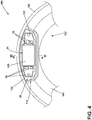
- the door cover 102 can have structural features to improve the operability of the user interface 30 within the door assembly 100, as shown in the cross-sectional view of the door cover 102.
- the door cover 102 includes an upper portion 122 and a lower portion 124.
- the upper portion 122 corresponds to the position of the user interface 30, and the upper portion is relatively flat.
- the lower portion 124 can be located outside the position of the user interface 30, and can have a convex surface in cross-section.
- FIG. 6 illustrates a cross-sectional view of the flat upper portion 122 of the door cover 102 within the door assembly 100. Behind the flat upper portion 122 of the door cover 102, the touch film 108 is positioned. Behind the touch film 108, the display module 34 is positioned within the display opening 116 of the intermediate door 104, immediately behind the touch film 108. By having the touch film 108 and the display module 34 adjacent the flat upper portion 122 of the door cover 102, any air gap that would exist between the door cover 102 and the display module 34 if the door cover 102 were curved is eliminated, such that improved touch performance is achieved by the touch film 108 and the display module 34.
- the upper portion 122 of the door cover 102 being flat also makes it easier for the touch film 108 and the at least one circuit board 112 to be adhered to the rear surface 118 of the door cover 102, with less chance of wrinkling or air bubbles as compared to adhesion to a curved surface. Additionally, the presence of the flat upper portion 122 of the door cover 102 results in the user interface 30 being presented to the user in a tilted manner, which improves visibility and ergonomic performance for the user, as the flat upper portion 122 is likely to be below the height of an average user. In this way, the flat upper portion 122 presents the user interface 30 to a user such that the display module 34 is visually tilted towards the user for ease of use. In an exemplary embodiment, the flat upper portion 122 of the door cover 102 where the user interface 30 is located is provided at an angle of 10.4° relative to vertical.
- the upper portion 122 and the lower portion 124 can have differing thicknesses, such that the upper portion 122 of the door cover 102 is thinner than the lower portion 124.
- the sensitivity, or the touch resolution, of the touch film 108 to a touch by a user can be improved.
- the lower portion 124 of the door cover can have a thickness of 3.5 millimeters, while the upper portion 122 has a thickness of 2.5 millimeters.
- the upper portion 122 can be both flat and have a reduced thickness in the same area, it is not required that the flat area and the area of reduced thickness are of identical shape and size. Further, where the upper portion 122 and the lower portion 124 meet, the thickness can gradually transition from the thickness of the upper portion 122 to the thickness of the lower portion 124, or the thickness can abruptly change at the point where the upper portion 122 and the lower portion 124 meet.
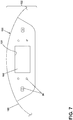
- FIG. 7 illustrates a front view of a visual appearance of a portion of the door cover 102.
- a masked portion 126 can be included to provide an opaque area of the door cover 102 to hide the components of the user interface 30, such as the at least one circuit board 112 or other electrical components.
- the masked portion 126 includes a mask opening 128 that corresponds to the touch film 108, the display module 34, and the display opening 116 of the intermediate door 104, such that the masked portion 126 does not impede the viewability of the display module 34.
- the masked portion 126 is a heat transfer foil decoration applied to the rear surface 118 of the door cover 102.
- the at least one circuit board 112 and corresponding adhesive layer 110 can be applied to the rear surface 118 of the door cover 102, even where the masked portion 126 is already present. It will be understood that any other suitable type of masking decoration can be applied other than the use of a heat transfer foil, non-limiting examples of which include hot stamping, ink, in-mold decoration, or in-mold labelling.
- a groove 120 can be seen in the front surface of the intermediate door 104.
- the groove 120 extends circumferentially about the touch film 108, display module 34, and the at least one circuit board 112.
- the groove 120 is positioned such that it can accommodate a gasket 134 within the groove 120.
- the gasket 134 can be seen in the cross-sectional view of FIG. 6 .
- the gasket 134 serves to ensure that any liquid and dust or debris within the door assembly 100, particularly between the intermediate door 104 and the door cover 102, is diverted away from the electronics of the user interface 30. While the gasket 134 and the groove 120 are shown as encircling the user interface 30 entirely, it will be understood that both the groove 120 and the gasket 134 can also extend only around an upper portion of the user interface 30, or in any other portion different than what is shown.
- FIG. 8 illustrates an enlarged rear perspective view of an upper portion of the outer door assembly 140, including an additional liquid diverting structure that is present on a rear surface 138 of the intermediate door 104.
- a water channel 136 (also visible in cross-section in FIG. 6 ) extends rearwardly from the rear surface 138 of the intermediate door 104. The water channel 136 is positioned above the display opening 116 of the intermediate door 104.
- the water channel 136 extends to a width that is at least the width of the display module 34 and the at least one circuit board 112, though it will be understood that the water channel 136 can be any suitable width such that any liquid that may be present within the door assembly 100, particularly between the intermediate door 104 and a rear door 130, is deflected away from the electronics of the user interface 30.
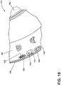
- the outer door assembly 140 comprises a plurality of fasteners that are used in the assembling of the outer door assembly 140, as illustrated in FIGS. 9 and 10 , which illustrate rear perspective views of the outer door assembly 140, including the door cover 102, the intermediate door 104, and the peripheral trim ring 106.
- the door cover 102 is coupled to the intermediate door 104 by a plurality of door cover hooks 144 that are received by door cover hook openings 142 provided within the intermediate door 104.
- there are provided eight sets of couplings of the door cover hooks 144 with the door cover hook openings 142 the eight sets being arranged along the periphery of the outer door assembly 140, and only along a lower portion of the periphery of the outer door assembly 140.
- any suitable number of sets of door cover hooks 144 and door cover hook openings 142 can be provided, and that they can be provided at any suitable point along the periphery of the outer door assembly 140.
- the peripheral trim ring 106 is coupled to the intermediate door 104 by a plurality of intermediate door hooks 152 that are received within receiving windows 150 provided on the peripheral trim ring 106, which can be seen in enlarged detail in FIGS. 11A and 11B .
- the receiving windows 150 on the peripheral trim ring 106 are shaped to receive the intermediate door hooks 152 such that rotation of the peripheral trim ring 106 about the peripheral edge of the intermediate door 104 is prevented when the peripheral trim ring 106 is coupled to the intermediate door 104.
- a third attachment feature of the outer door assembly 140 involves the coupling of the door cover 102, the intermediate door 104, and the peripheral trim ring 106 by the use of heat staking.
- a plurality of heat stake posts 148 are provided on the peripheral trim ring 106, projecting rearwardly from the peripheral trim ring 106 towards the treating chamber 18.
- the heat stake posts 148 are received by a corresponding number of heat stake towers 146 formed in the intermediate door 104 and defining receiving openings for the heat stake posts 148.
- a plurality of sets of the heat stake posts 148 and the heat stake towers 146 can be distributed about the periphery of the outer door assembly 140, such that the heat stake posts 148 are arranged about a perimeter of the intermediate door 104 and the heat stake towers 146 are arranged about a perimeter of the peripheral trim ring 106.
- the heat stake posts 148 can be received within the heat stake towers 146 of the intermediate door 104 when the door cover 102 and the intermediate door 104 have been coupled together via the door cover hooks 144 and the door cover hook openings 142, such that the peripheral trim ring 106 sandwiches the door cover 102 between the peripheral trim ring 106 and the intermediate door 104.
- Alignment locators can be provided to ensure that the door cover 102, the intermediate door 104, and the peripheral trim ring 106 are aligned properly.
- Non-limiting examples of such an alignment locator can include notches, protrusions, or indentations that are complementary to one another between the door cover 102, the intermediate door 104, and the peripheral trim ring 106. Any suitable number of such alignment locators can be provided, including a plurality of alignment locators or only a single alignment locator.
- heat stake posts 148 are illustrated herein as being provided on the peripheral trim ring 106 and the heat stake towers 146 defining the receiving openings are illustrated herein as being provided on the intermediate door 104, it will be understood that the heat stake posts 148 can be provided on either the peripheral trim ring 106 or the intermediate door 104, with the heat stake towers 146 defining the receiving openings can be provided on the other of the peripheral trim ring 106 or the intermediate door 104, such that the heat stake posts 148 and the heat stake towers 146 defining the receiving openings collectively form first and second parts of a heat stake connection.
- FIG. 12A a schematic cross-sectional view of the heat stake post 148 and heat stake tower 146 are shown.
- heat can be applied by a heating apparatus 154 in order to melt the top of the heat stake posts 148 while applying downward pressure to create a cap, illustrated herein as a mushroom-shaped top, on the heat stake posts 148 and couple the peripheral trim ring 106 to the intermediate door 104, as shown in FIG. 12B .
- a cap illustrated herein as a mushroom-shaped or flattened top, it will be understood that the cap can have any suitable shape.
- the heating apparatus 154 can be a heating machine, a non-limiting example of which includes an ultrasonic heating machine, though it will be understood that any suitable heating device can be used.
- the melting of the heat stake towers 146 creates a robust coupling between the peripheral trim ring 106 and the intermediate door 104, such that there is no looseness between the two parts to create squeaking or rattling during the operation of the laundry treating appliance 10.
- FIG. 13 illustrates an exploded view of an exemplary embodiment of the inner door assembly 160 that can be used in the door assembly 100.
- the inner door assembly 160 can be used to form the door assembly 100 for a laundry washing appliance, though it will be understood that the inner door assembly 160 can also be used in any other type of laundry treating appliance 10.
- the inner door assembly 160 comprises the rear door 130, the hinge assembly 64, and a door inner window 132.
- the door inner window 132 can have the shape of a bowl, although it will be understood that any suitable shape can be used, including a flat window, or a concave or convex window that is not shaped like a bowl.
- the rear door 130 includes a door inner window opening 162 that is designed to receive the door inner window 132.
- both the rear door 130 and the door inner window 132 can be formed of plastic, although it will be understood that the rear door 130 can also be formed from metal, composite, or other suitable material, while the door inner window 132 can also be formed of glass.
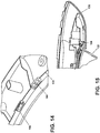
- the inner door assembly 160 includes fastening elements for coupling the door inner window 132 to the rear door 130, which are illustrated in FIG. 14 in the form of a plurality of holding snaps 164 and a plurality of centering snaps 166 provided along the periphery of the door inner window opening 162 of the rear door 130. As shown in an enlarged cross-sectional view in FIG. 15 , the holding snaps 164 sandwich the door inner window 132 against the rear door 130 securely such that the door inner window 132 is tightly held and does not allow for gaps between the door inner window 132 and the rear door 130.
- the centering snaps 166 are shown in enlarged cross-sectional view in FIG. 16 .
- the centering snaps 166 are resiliently biased against the door inner window 132.
- the centering snaps 166 are distributed evenly about the periphery of the door inner window opening 162 of the rear door 130 such that an even and balanced amount of pressure is applied to the door inner window 132 by the centering snaps 166 from any given direction. In this way, the biasing of the centering snaps 166 against the door inner window 132 serves to center the door inner window 132 within the door inner window opening 162.
- FIG. 17 illustrates a rear perspective view of an upper portion of the rear door 130.
- a rear surface 170 of the rear door 130 contains at least one set of speaker openings 168 that pass through the rear surface 170 of the rear door 130.
- two sets of speaker openings 168 are provided, one set on either side of the position of the user interface 30 and the display module 34.
- the speaker openings 168 allow sound from the user interface 30 to exit the door assembly 100 and be projected such that a user can hear the audible sounds from the user interface 30. It will be understood that any suitable number of speaker openings 168 or sets of speaker openings 168 can be provided, including a single set of speaker openings 168, and that they can be provided at any suitable location on the rear door 130.
- FIG. 18 illustrates an exploded view of another exemplary embodiment of the inner door assembly 180 that can be used in the door assembly 100.
- the inner door assembly 180 can be used to form the door assembly 100 for a laundry drying appliance, though it will be understood that the inner door assembly 180 can also be used in any other type of laundry treating appliance 10.
- the inner door assembly 180 comprises a rear door 230, the hinge assembly 64, and a door window 232.
- the rear door 230 includes a door window opening 262 that is designed to receive the door window 232.
- the door window 232 When the door window 232 is received within the door window opening 262 of the rear door 230, and the inner door assembly 180 is coupled to the outer door assembly 140 to form the door assembly 100, the door window 232 is aligned with the central opening 114 of the intermediate door 104 to allow a user to view the treating chamber 18 when the door assembly 100 is in the closed condition.
- a seal 186 can be provided where the door window 232 is received within the door window opening 262.
- the rear door 230 is formed of metal, while the door window 232 is formed of glass, although it will be understood that the rear door 230 can also be formed from plastic or other suitable material, while the door window 232 can also be formed of plastic.
- the inner door assembly 180 includes fastening elements for coupling the door window 232 to the rear door 230, which can be in the form of holding snaps 164 and centering snaps 166 as described previously within the inner door assembly 160, or the fastening elements can be provided in the form of clamps 188 as shown in FIG. 18 .
- the clamps can be fastened to the rear door 230 in order to hold the door window 232 in place within the door window opening 262.
- both the clamps 188 and the rear door 230 are formed of steel.
- the inner door assembly 180 further includes a handle cover 182 and a hinge cover 184 that are coupled to the rear door 230.
- the hinge assembly 64 can be attached to either side of the rear door 230, depending on the preference of the user. Whichever side the user chooses of the rear door 230 to attach the hinge assembly 64 to, the hinge cover 184 can be coupled to the rear door 230 on the side corresponding to the position of the hinge assembly 64, with the handle cover 182 being coupled to the rear door 230 on the side opposite the position of the hinge assembly 64.
- both the handle cover 182 and the hinge cover 184 are formed of plastic, though it will be understood that any suitable material, including metal, can be used.
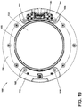
- FIG. 19 illustrates a rear view of the inner door assembly 180 with the hinge assembly 64, the hinge cover 184, and the handle cover 182 in position and coupled to the rear door 230.
- Both the handle cover 182 and the hinge cover 184 have a set of speaker openings 168 at both an upper portion and a lower portion, such that even if the handle cover 182 and the hinge cover 184 were switched to opposite sides of the rear door 230, along with the hinge assembly 64, the user is assured that a set of speaker openings 168 will still be in place for optimal sound transmission.
- FIG. 20 illustrates a rear perspective view of the rear door 230, including a hole pattern 190 that can be provided in the rear door 230.
- the hole pattern 190 allows for sound to exit the rear door 230 from the user interface 30, such that the sound can most effectively reach the speaker openings 168 of the handle cover 182 or the hinge cover 184 in order to be transmitted to the user from the door assembly 100.
- the hole pattern 190 is illustrated herein as being provided either on a horizontal or vertical surface of the rear door 230. It will be understood that such arrangements of the hole pattern 190 can be provided either on their own or together and either above or below the hinge assembly 64.
- the portion of the rear door 230 either above or below the hinge assembly 64 can be provided with a hole pattern 190 on a horizontal surface of the rear door 230, on a vertical surface of the rear door 230, or both the horizontal and the vertical surfaces of the rear door 230.
- the portions of the rear door 230 above and below the hinge assembly 64 can be provided with identical hole patterns 190, or the hole pattern 190 can differ above and below the hinge assembly 64.
- the display module 34 can then be fastened to the intermediate door 104.
- the display module 34 can be fastened to the intermediate door 104 using any suitable fastener, non-limiting examples of which include screws, bolts, snaps, or clamps.
- the display module 34 is fastened to the intermediate door 104 such that the display module 34 is aligned with the display opening 116 of the intermediate door 104, and therefore also aligned with the touch film 108 and the flat upper portion 122 of the door cover 102.
- either of the inner door assemblies 160, 180 can be attached to the outer door assembly 140 by means of suitable fasteners, non-limiting examples of which include screws, bolts, snaps, or clamps.
- the hinge assembly 64 which is attached as a part of the inner door assembly 160, 180, can then be attached to the cabinet 12 by means of suitable fasteners, non-limiting examples of which include screws, bolts, snaps, or clamps.
- the embodiments described herein set forth a door assembly for a laundry treating appliance that allows for a user interface to be used that is appealing and ergonomically satisfying for a user, as well as setting forth a variety of features for ensuring the stability of the door assembly, for protecting the user interface and associated electronics from liquid, for improving the usability of the touch interface and improving sound transmission to a user, and for providing flexibility for the type of laundry treating appliance that the door assembly can be used with, even allowing a user to select which way they would like the door to open in certain embodiments.
- a laundry treating appliance comprising a cabinet defining an interior, a drum located within the interior and defining a treating chamber, and a door assembly coupled to the cabinet to selectively open and close the treating chamber and at least partially defining the treating chamber when the door assembly is in a closed condition, the door assembly comprising an intermediate door having front and rear surfaces and defining an opening, a user interface mounted to the intermediate door, a door cover adjacent the front surface of the intermediate door and overlying the user interface, a rear door adjacent the rear surface of the intermediate door, a door window mounted to the rear door and overlying the opening, a trim element provided about at least a periphery of the intermediate door, and a heat stake connection comprising a plurality of posts on one of the intermediate door or the trim element and a plurality of receiving on the other of the intermediate door or the trim element, the posts configured to be received within the receiving openings and thermally deformed to create a plurality of caps to secure the trim element to the intermediate door.
- a laundry treating appliance wherein the posts are melted to create the plurality of caps to secure the trim element to the intermediate door.
- a laundry treating appliance wherein the melting is done by ultrasonic heating of the posts.
Landscapes
- Engineering & Computer Science (AREA)
- Textile Engineering (AREA)
- Main Body Construction Of Washing Machines And Laundry Dryers (AREA)
- Detail Structures Of Washing Machines And Dryers (AREA)
Applications Claiming Priority (2)
| Application Number | Priority Date | Filing Date | Title |
|---|---|---|---|
| US201762587078P | 2017-11-16 | 2017-11-16 | |
| US16/137,093 US11118295B2 (en) | 2017-11-16 | 2018-09-20 | Laundry treating appliance having a user interface within a door assembly |
Publications (2)
| Publication Number | Publication Date |
|---|---|
| EP3486366A1 true EP3486366A1 (de) | 2019-05-22 |
| EP3486366B1 EP3486366B1 (de) | 2022-06-01 |
Family
ID=64277630
Family Applications (1)
| Application Number | Title | Priority Date | Filing Date |
|---|---|---|---|
| EP18205788.5A Not-in-force EP3486366B1 (de) | 2017-11-16 | 2018-11-12 | Wäschebehandlungsvorrichtung mit einer benutzerschnittstelle innerhalb einer türanordnung |
Country Status (2)
| Country | Link |
|---|---|
| US (4) | US11118295B2 (de) |
| EP (1) | EP3486366B1 (de) |
Families Citing this family (17)
| Publication number | Priority date | Publication date | Assignee | Title |
|---|---|---|---|---|
| CN106988089B (zh) * | 2016-01-20 | 2020-09-04 | 青岛海尔滚筒洗衣机有限公司 | 一种门体轴套的固定结构及滚筒洗衣机 |
| USD878687S1 (en) | 2017-05-31 | 2020-03-17 | Whirlpool Corporation | Fabric care appliance |
| US11118295B2 (en) | 2017-11-16 | 2021-09-14 | Whirlpool Corporation | Laundry treating appliance having a user interface within a door assembly |
| USD899720S1 (en) * | 2017-12-21 | 2020-10-20 | Whirlpool Corporation | Laundry treating appliance |
| USD885696S1 (en) * | 2018-01-03 | 2020-05-26 | Samsung Electronics Co., Ltd. | Dryer |
| US11118294B2 (en) * | 2018-01-08 | 2021-09-14 | Lg Electronics Inc. | Laundry treatment machine |
| US10526745B2 (en) * | 2018-04-19 | 2020-01-07 | Haier Us Appliance Solutions, Inc. | Door for improved air flow in a dryer appliance |
| US11182123B2 (en) * | 2019-04-30 | 2021-11-23 | Whirlpool Corporation | User-interface system for a laundry appliance |
| US11686032B2 (en) | 2019-04-30 | 2023-06-27 | Whirlpool Corporation | User-interface system for a laundry appliance |
| KR102809589B1 (ko) * | 2019-07-17 | 2025-05-20 | 삼성전자주식회사 | 의류관리장치 |
| CN112442868B (zh) * | 2019-08-14 | 2023-12-22 | 佛山市顺德海尔电器有限公司 | 一种衣物处理设备的上盖及衣物处理设备 |
| CN110761029A (zh) * | 2019-10-18 | 2020-02-07 | 衣锦浣香电子商务有限公司 | 一种基于rfid的家用智能洗衣机语音控制系统 |
| USD962569S1 (en) * | 2020-07-21 | 2022-08-30 | Haier Us Appliance Solutions, Inc. | Front load washer vent |
| CN114687166A (zh) * | 2022-03-30 | 2022-07-01 | 创维电器股份有限公司 | 一种洗衣机的内嵌式门组件 |
| KR20250045838A (ko) * | 2023-09-26 | 2025-04-02 | 엘지전자 주식회사 | 의류처리장치 |
| US20260002313A1 (en) * | 2024-07-01 | 2026-01-01 | Haier Us Appliance Solutions, Inc. | Laundry appliance door assemblies and methods of manufacturing such assemblies |
| US20260002312A1 (en) * | 2024-07-01 | 2026-01-01 | Haier Us Appliance Solutions, Inc. | Laundry appliance door assemblies and methods of manufacturing such assemblies |
Citations (5)
| Publication number | Priority date | Publication date | Assignee | Title |
|---|---|---|---|---|
| WO2012153261A1 (en) * | 2011-05-11 | 2012-11-15 | BSH Bosch und Siemens Hausgeräte GmbH | Door for front-loading washing machine |
| EP2843107A1 (de) * | 2013-08-30 | 2015-03-04 | Electrolux Appliances Aktiebolag | Türanordnung einer Wäschebehandlungsvorrichtung |
| WO2016135285A1 (en) * | 2015-02-27 | 2016-09-01 | Electrolux Appliances Aktiebolag | Laundry drying machine |
| US20170121891A1 (en) * | 2015-11-02 | 2017-05-04 | Lg Electronics Inc. | Laundry treating apparatus and method of fabricating a laundry treating apparatus door |
| WO2017167080A1 (zh) * | 2016-03-30 | 2017-10-05 | 青岛海尔滚筒洗衣机有限公司 | 带装饰圈的洗衣机门体、洗衣机及洗衣方法 |
Family Cites Families (57)
| Publication number | Priority date | Publication date | Assignee | Title |
|---|---|---|---|---|
| IT210393Z2 (it) | 1987-06-02 | 1988-12-30 | Eurodomestici Ind Riunite | Oblo' per lavabiancheria e simili avente una controcornice intercambiabile e mezzi atti a garantirne la tenuta anche senza di essa. |
| DE19515040C2 (de) | 1995-04-24 | 1999-09-02 | Bosch Siemens Hausgeraete | Bullaugentür für eine von vorn beschickbare Trommelwaschmaschine |
| ES2151336B1 (es) | 1997-02-21 | 2001-06-16 | Balay Sa | Sistema de union entre el marco y el cristal de puertas de lavadoras. |
| KR100379468B1 (ko) | 2000-06-21 | 2003-04-10 | 엘지전자 주식회사 | 경사투입 세탁기의 조작부 체결구조 |
| KR100452372B1 (ko) | 2002-07-29 | 2004-10-12 | 엘지전자 주식회사 | 건조기의 도어 |
| KR100595180B1 (ko) | 2002-07-31 | 2006-07-03 | 엘지전자 주식회사 | 빨래건조기/드럼세탁기의 도어 |
| DE602004026450D1 (de) | 2003-08-11 | 2010-05-20 | Arcelik Anonim Sirketi Tuzla | Waschtrockner |
| CN2701894Y (zh) | 2003-09-30 | 2005-05-25 | 海尔集团公司 | 具有卡扣式门体的洗衣机 |
| DE112006000006B4 (de) | 2005-01-25 | 2014-02-20 | Lg Electronics Inc. | Tür für eine Waschmaschine oder einen Trockner |
| CA2508607C (en) | 2005-05-30 | 2007-09-11 | Camco Inc. | Clothes dryer door assembly |
| ITTO20050453A1 (it) | 2005-06-29 | 2006-12-30 | Indesit Co Spa | Sportello per elettrodomestico in particolare per macchina, lavasciuga o asciugabiancheria a carica frontale o sostanzialmente frontale |
| KR101138697B1 (ko) * | 2005-06-30 | 2012-06-14 | 엘지전자 주식회사 | 드럼식 건조기용 도어 어셈블리 |
| DE102005041113A1 (de) | 2005-08-30 | 2007-03-01 | BSH Bosch und Siemens Hausgeräte GmbH | Kapazitiver Annäherungsschalter und Haushaltsgerät mit einem solchen |
| DE102005041112A1 (de) | 2005-08-30 | 2007-03-01 | BSH Bosch und Siemens Hausgeräte GmbH | Kapazitiver Annäherungsschalter und Haushaltgerät mit einem solchen |
| US7320186B2 (en) | 2005-09-02 | 2008-01-22 | Bsh Home Appliances Corporation | Appliance door having see-through portion |
| DE102006036352B4 (de) | 2006-08-02 | 2009-11-12 | Miele & Cie. Kg | Bullaugentür für eine frontbeschickbare Wäschebehandlungsmaschine wie Waschmaschine, Waschtrockner oder Wäschetrockner |
| US7686127B2 (en) | 2007-01-04 | 2010-03-30 | Whirlpool Corporation | Acoustic chamber as part of adapter or appliance |
| KR101278159B1 (ko) | 2007-06-05 | 2013-06-27 | 삼성전자주식회사 | 드럼세탁기 및 드럼세탁기의 도어 |
| JP4483913B2 (ja) | 2007-09-03 | 2010-06-16 | パナソニック株式会社 | 洗濯機 |
| DE102007061522A1 (de) | 2007-12-20 | 2009-06-25 | BSH Bosch und Siemens Hausgeräte GmbH | Haushaltsgerät |
| DE102008012192A1 (de) | 2008-03-03 | 2009-09-10 | Miele & Cie. Kg | Frontbeschickbare Wäschebehandlungsmaschine und Tür für eine frontbeschickbare Wäschebehandlungsmaschine |
| EP2107152B1 (de) | 2008-03-31 | 2014-06-11 | Electrolux Home Products Corporation N.V. | Elektrisches Gerät mit verbessertem Türmechanismus |
| KR101464537B1 (ko) | 2008-10-01 | 2014-11-24 | 삼성전자주식회사 | 디지털 카메라의 사용자 인터페이스 모듈 및 이를 구비한 디지털 카메라 |
| KR101555586B1 (ko) | 2009-04-10 | 2015-09-24 | 엘지전자 주식회사 | 가전기기 |
| CA2724487A1 (en) | 2009-12-08 | 2011-06-08 | Magna International Inc. | Appliance doors having integrated lighting and controls |
| US9212449B2 (en) | 2010-08-31 | 2015-12-15 | Bsh Home Appliances Corporation | Structural door bowl for a household appliance door |
| US9093884B2 (en) | 2010-10-20 | 2015-07-28 | Nidec Motor Corporation | Integrated motor and control |
| US9030837B2 (en) | 2011-06-10 | 2015-05-12 | Scott Moncrieff | Injection molded control panel with in-molded decorated plastic film that includes an internal connector |
| DE102011078765A1 (de) | 2011-07-06 | 2013-01-10 | BSH Bosch und Siemens Hausgeräte GmbH | Geschirrspülmaschine mit zumindest einem lichtdurchlässigen Teilbereich auf ihrer Türinnenwandung |
| KR20130039457A (ko) | 2011-10-12 | 2013-04-22 | 삼성전자주식회사 | 컨트롤 패널 어셈블리 및 이를 구비하는 세탁기 |
| EP2604750A1 (de) | 2011-12-16 | 2013-06-19 | Electrolux Home Products Corporation N.V. | Haushaltswasch- und Wäschetrocknermaschine |
| KR101880082B1 (ko) | 2012-03-27 | 2018-07-20 | 삼성전자주식회사 | 세탁기 |
| US20130277353A1 (en) | 2012-04-23 | 2013-10-24 | Dacor, Inc. | Android controlled oven |
| EP2677076A1 (de) | 2012-06-18 | 2013-12-25 | Electrolux Home Products Corporation N.V. | Wäschebehandlungsvorrichtung mit Türanordnung |
| JP2014014588A (ja) | 2012-07-11 | 2014-01-30 | Panasonic Corp | 洗濯機の操作表示装置 |
| CN104717910A (zh) | 2012-09-20 | 2015-06-17 | 咖世家有限公司 | 饮料机 |
| EP3181750B1 (de) * | 2012-12-06 | 2019-03-20 | Electrolux Home Products Corporation N.V. | Wäschebehandlungsvorrichtung mit türanordnung |
| WO2014118295A1 (de) | 2013-01-30 | 2014-08-07 | MKN Maschinenfabrik Kurt Neubauer GmbH & Co. KG | Gargerät mit transparentem display |
| CN103132292B (zh) | 2013-02-21 | 2015-08-05 | 松下家电研究开发(杭州)有限公司 | 一种防水型控制面板及洗衣机 |
| BR202013015525U2 (pt) | 2013-06-20 | 2015-08-04 | Rafael Martins Silva | Disposição introduzida em painel de acionamento de máquina de lavar roupas |
| KR102127719B1 (ko) * | 2013-07-08 | 2020-06-29 | 삼성전자주식회사 | 세탁기 |
| KR20150006264A (ko) | 2013-07-08 | 2015-01-16 | 삼성전자주식회사 | 드럼세탁기 |
| PL2837726T3 (pl) | 2013-08-13 | 2017-06-30 | Electrolux Appliances Aktiebolag | Urządzenie do obróbki pralniczej mające zespół panelu sterującego |
| CN203530713U (zh) | 2013-09-26 | 2014-04-09 | 无锡小天鹅股份有限公司 | 洗衣机 |
| CN103526515B (zh) | 2013-09-26 | 2016-06-29 | 无锡小天鹅股份有限公司 | 洗衣机 |
| EP3164537B1 (de) | 2014-07-02 | 2018-01-31 | Arçelik Anonim Sirketi | Steuertafelanordnung für ein elektrisches haushaltsgerät |
| DE202014005929U1 (de) | 2014-07-21 | 2014-08-07 | BSH Bosch und Siemens Hausgeräte GmbH | Lautsprechergehäuse und Haushaltsgerät mit einem solchen Lautsprechergehäuse |
| EP3189181A1 (de) | 2014-09-03 | 2017-07-12 | Arçelik Anonim Sirketi | Waschmaschine und/oder trockner mit strukturell verbessertem befestigungsmechanismus für die vordertürscheibe |
| KR102265272B1 (ko) | 2014-11-04 | 2021-06-15 | 삼성전자주식회사 | 인쇄회로기판 와 인쇄회로기판 어셈블리 및 이를 구비하는 세탁기 |
| CN105671866A (zh) | 2014-11-17 | 2016-06-15 | 青岛海尔滚筒洗衣机有限公司 | 滚筒洗衣机前盖门及滚筒洗衣机 |
| KR101668922B1 (ko) | 2014-12-24 | 2016-10-24 | 엘지전자 주식회사 | 디스플레이 어셈블리가 구비된 가전제품 및 그 제조 방법 |
| CN204551072U (zh) | 2015-04-03 | 2015-08-12 | 惠而浦(中国)股份有限公司 | 一种具有彩屏显示及触摸操控功能的滚筒洗衣机门盖 |
| WO2017020961A1 (en) | 2015-08-06 | 2017-02-09 | Arcelik Anonim Sirketi | Display assembly for household appliance |
| CN206070194U (zh) | 2015-11-02 | 2017-04-05 | Lg电子株式会社 | 衣物处理装置 |
| KR101708351B1 (ko) * | 2015-11-02 | 2017-02-20 | 엘지전자 주식회사 | 의류처리장치 |
| KR101708355B1 (ko) | 2015-11-02 | 2017-02-20 | 엘지전자 주식회사 | 의류처리장치 |
| US11118295B2 (en) * | 2017-11-16 | 2021-09-14 | Whirlpool Corporation | Laundry treating appliance having a user interface within a door assembly |
-
2018
- 2018-09-20 US US16/137,093 patent/US11118295B2/en not_active Expired - Fee Related
- 2018-11-12 EP EP18205788.5A patent/EP3486366B1/de not_active Not-in-force
-
2021
- 2021-08-16 US US17/402,888 patent/US11959220B2/en active Active
-
2024
- 2024-03-25 US US18/615,477 patent/US12351973B2/en active Active
-
2025
- 2025-06-10 US US19/233,007 patent/US20250305204A1/en active Pending
Patent Citations (5)
| Publication number | Priority date | Publication date | Assignee | Title |
|---|---|---|---|---|
| WO2012153261A1 (en) * | 2011-05-11 | 2012-11-15 | BSH Bosch und Siemens Hausgeräte GmbH | Door for front-loading washing machine |
| EP2843107A1 (de) * | 2013-08-30 | 2015-03-04 | Electrolux Appliances Aktiebolag | Türanordnung einer Wäschebehandlungsvorrichtung |
| WO2016135285A1 (en) * | 2015-02-27 | 2016-09-01 | Electrolux Appliances Aktiebolag | Laundry drying machine |
| US20170121891A1 (en) * | 2015-11-02 | 2017-05-04 | Lg Electronics Inc. | Laundry treating apparatus and method of fabricating a laundry treating apparatus door |
| WO2017167080A1 (zh) * | 2016-03-30 | 2017-10-05 | 青岛海尔滚筒洗衣机有限公司 | 带装饰圈的洗衣机门体、洗衣机及洗衣方法 |
Also Published As
| Publication number | Publication date |
|---|---|
| US20190145041A1 (en) | 2019-05-16 |
| US20240229340A1 (en) | 2024-07-11 |
| US20210372028A1 (en) | 2021-12-02 |
| US11118295B2 (en) | 2021-09-14 |
| US11959220B2 (en) | 2024-04-16 |
| US20250305204A1 (en) | 2025-10-02 |
| US12351973B2 (en) | 2025-07-08 |
| EP3486366B1 (de) | 2022-06-01 |
Similar Documents
| Publication | Publication Date | Title |
|---|---|---|
| US12351973B2 (en) | Door assembly for a laundry treating appliance | |
| US10253441B2 (en) | Laundry appliance door assembly | |
| US11920285B2 (en) | Laundry treating appliance door assembly | |
| EP1781856B1 (de) | Haushaltsgerät | |
| US20110296630A1 (en) | Appliance lid having a viewing window partially encapsulated between one or more clamshells | |
| US20040169449A1 (en) | Cabinet cover of home appliance | |
| US7934399B2 (en) | Drum type washing machine | |
| KR20170040710A (ko) | 가전제품용 외장부재 | |
| US20040150303A1 (en) | Control panel assembly | |
| GB2342438A (en) | A front panel assembly for a microwave oven | |
| AU2014224510B2 (en) | Household electrical appliance control panel and method of manufacturing such a control panel | |
| KR100793770B1 (ko) | 틸팅형 드럼세탁기의 캐비닛 커버와 톱플레이트 설치 구조 | |
| JP2019170614A (ja) | 洗濯機 | |
| US20040230321A1 (en) | Operating panel configuration for an electrical demestic appliance | |
| KR20210005987A (ko) | 가전제품용 외장부재 제조 방법 | |
| KR101199356B1 (ko) | 콘트롤 패널의 투명창 결합구조 | |
| KR100715539B1 (ko) | 세탁기 | |
| KR200357925Y1 (ko) | 전자 레인지의 컨트롤 어셈블리 | |
| KR20170082707A (ko) | 컨트롤 패널 장치 및 이를 구비한 세탁기 | |
| US20080053160A1 (en) | Laundry machine | |
| WO2005104888A1 (en) | Method for inserting a rigid display module in clothing or a fashion accessory and article fitted with such a module | |
| KR100953970B1 (ko) | 전자레인지용 도어 | |
| CA2752940A1 (en) | Appliance lid having a viewing window partially encapsulated between one or more clamshells | |
| JP2014054489A (ja) | 洗濯機 |
Legal Events
| Date | Code | Title | Description |
|---|---|---|---|
| PUAI | Public reference made under article 153(3) epc to a published international application that has entered the european phase |
Free format text: ORIGINAL CODE: 0009012 |
|
| STAA | Information on the status of an ep patent application or granted ep patent |
Free format text: STATUS: THE APPLICATION HAS BEEN PUBLISHED |
|
| AK | Designated contracting states |
Kind code of ref document: A1 Designated state(s): AL AT BE BG CH CY CZ DE DK EE ES FI FR GB GR HR HU IE IS IT LI LT LU LV MC MK MT NL NO PL PT RO RS SE SI SK SM TR |
|
| AX | Request for extension of the european patent |
Extension state: BA ME |
|
| STAA | Information on the status of an ep patent application or granted ep patent |
Free format text: STATUS: REQUEST FOR EXAMINATION WAS MADE |
|
| 17P | Request for examination filed |
Effective date: 20191122 |
|
| RBV | Designated contracting states (corrected) |
Designated state(s): AL AT BE BG CH CY CZ DE DK EE ES FI FR GB GR HR HU IE IS IT LI LT LU LV MC MK MT NL NO PL PT RO RS SE SI SK SM TR |
|
| GRAP | Despatch of communication of intention to grant a patent |
Free format text: ORIGINAL CODE: EPIDOSNIGR1 |
|
| STAA | Information on the status of an ep patent application or granted ep patent |
Free format text: STATUS: GRANT OF PATENT IS INTENDED |
|
| RIC1 | Information provided on ipc code assigned before grant |
Ipc: D06F 105/60 20200101ALN20220303BHEP Ipc: D06F 101/00 20200101ALN20220303BHEP Ipc: D06F 39/14 20060101AFI20220303BHEP |
|
| GRAS | Grant fee paid |
Free format text: ORIGINAL CODE: EPIDOSNIGR3 |
|
| INTG | Intention to grant announced |
Effective date: 20220323 |
|
| GRAA | (expected) grant |
Free format text: ORIGINAL CODE: 0009210 |
|
| STAA | Information on the status of an ep patent application or granted ep patent |
Free format text: STATUS: THE PATENT HAS BEEN GRANTED |
|
| AK | Designated contracting states |
Kind code of ref document: B1 Designated state(s): AL AT BE BG CH CY CZ DE DK EE ES FI FR GB GR HR HU IE IS IT LI LT LU LV MC MK MT NL NO PL PT RO RS SE SI SK SM TR |
|
| REG | Reference to a national code |
Ref country code: GB Ref legal event code: FG4D |
|
| REG | Reference to a national code |
Ref country code: AT Ref legal event code: REF Ref document number: 1495435 Country of ref document: AT Kind code of ref document: T Effective date: 20220615 Ref country code: CH Ref legal event code: EP |
|
| REG | Reference to a national code |
Ref country code: IE Ref legal event code: FG4D |
|
| REG | Reference to a national code |
Ref country code: DE Ref legal event code: R096 Ref document number: 602018036140 Country of ref document: DE |
|
| REG | Reference to a national code |
Ref country code: LT Ref legal event code: MG9D |
|
| REG | Reference to a national code |
Ref country code: NL Ref legal event code: MP Effective date: 20220601 |
|
| PG25 | Lapsed in a contracting state [announced via postgrant information from national office to epo] |
Ref country code: SE Free format text: LAPSE BECAUSE OF FAILURE TO SUBMIT A TRANSLATION OF THE DESCRIPTION OR TO PAY THE FEE WITHIN THE PRESCRIBED TIME-LIMIT Effective date: 20220601 Ref country code: NO Free format text: LAPSE BECAUSE OF FAILURE TO SUBMIT A TRANSLATION OF THE DESCRIPTION OR TO PAY THE FEE WITHIN THE PRESCRIBED TIME-LIMIT Effective date: 20220901 Ref country code: LT Free format text: LAPSE BECAUSE OF FAILURE TO SUBMIT A TRANSLATION OF THE DESCRIPTION OR TO PAY THE FEE WITHIN THE PRESCRIBED TIME-LIMIT Effective date: 20220601 Ref country code: HR Free format text: LAPSE BECAUSE OF FAILURE TO SUBMIT A TRANSLATION OF THE DESCRIPTION OR TO PAY THE FEE WITHIN THE PRESCRIBED TIME-LIMIT Effective date: 20220601 Ref country code: GR Free format text: LAPSE BECAUSE OF FAILURE TO SUBMIT A TRANSLATION OF THE DESCRIPTION OR TO PAY THE FEE WITHIN THE PRESCRIBED TIME-LIMIT Effective date: 20220902 Ref country code: FI Free format text: LAPSE BECAUSE OF FAILURE TO SUBMIT A TRANSLATION OF THE DESCRIPTION OR TO PAY THE FEE WITHIN THE PRESCRIBED TIME-LIMIT Effective date: 20220601 Ref country code: ES Free format text: LAPSE BECAUSE OF FAILURE TO SUBMIT A TRANSLATION OF THE DESCRIPTION OR TO PAY THE FEE WITHIN THE PRESCRIBED TIME-LIMIT Effective date: 20220601 Ref country code: BG Free format text: LAPSE BECAUSE OF FAILURE TO SUBMIT A TRANSLATION OF THE DESCRIPTION OR TO PAY THE FEE WITHIN THE PRESCRIBED TIME-LIMIT Effective date: 20220901 |
|
| PGFP | Annual fee paid to national office [announced via postgrant information from national office to epo] |
Ref country code: GB Payment date: 20220922 Year of fee payment: 5 |
|
| REG | Reference to a national code |
Ref country code: AT Ref legal event code: MK05 Ref document number: 1495435 Country of ref document: AT Kind code of ref document: T Effective date: 20220601 |
|
| PG25 | Lapsed in a contracting state [announced via postgrant information from national office to epo] |
Ref country code: RS Free format text: LAPSE BECAUSE OF FAILURE TO SUBMIT A TRANSLATION OF THE DESCRIPTION OR TO PAY THE FEE WITHIN THE PRESCRIBED TIME-LIMIT Effective date: 20220601 Ref country code: PL Free format text: LAPSE BECAUSE OF FAILURE TO SUBMIT A TRANSLATION OF THE DESCRIPTION OR TO PAY THE FEE WITHIN THE PRESCRIBED TIME-LIMIT Effective date: 20220601 Ref country code: LV Free format text: LAPSE BECAUSE OF FAILURE TO SUBMIT A TRANSLATION OF THE DESCRIPTION OR TO PAY THE FEE WITHIN THE PRESCRIBED TIME-LIMIT Effective date: 20220601 |
|
| PGFP | Annual fee paid to national office [announced via postgrant information from national office to epo] |
Ref country code: FR Payment date: 20220908 Year of fee payment: 5 |
|
| PG25 | Lapsed in a contracting state [announced via postgrant information from national office to epo] |
Ref country code: NL Free format text: LAPSE BECAUSE OF FAILURE TO SUBMIT A TRANSLATION OF THE DESCRIPTION OR TO PAY THE FEE WITHIN THE PRESCRIBED TIME-LIMIT Effective date: 20220601 |
|
| PG25 | Lapsed in a contracting state [announced via postgrant information from national office to epo] |
Ref country code: SM Free format text: LAPSE BECAUSE OF FAILURE TO SUBMIT A TRANSLATION OF THE DESCRIPTION OR TO PAY THE FEE WITHIN THE PRESCRIBED TIME-LIMIT Effective date: 20220601 Ref country code: SK Free format text: LAPSE BECAUSE OF FAILURE TO SUBMIT A TRANSLATION OF THE DESCRIPTION OR TO PAY THE FEE WITHIN THE PRESCRIBED TIME-LIMIT Effective date: 20220601 Ref country code: RO Free format text: LAPSE BECAUSE OF FAILURE TO SUBMIT A TRANSLATION OF THE DESCRIPTION OR TO PAY THE FEE WITHIN THE PRESCRIBED TIME-LIMIT Effective date: 20220601 Ref country code: PT Free format text: LAPSE BECAUSE OF FAILURE TO SUBMIT A TRANSLATION OF THE DESCRIPTION OR TO PAY THE FEE WITHIN THE PRESCRIBED TIME-LIMIT Effective date: 20221003 Ref country code: EE Free format text: LAPSE BECAUSE OF FAILURE TO SUBMIT A TRANSLATION OF THE DESCRIPTION OR TO PAY THE FEE WITHIN THE PRESCRIBED TIME-LIMIT Effective date: 20220601 Ref country code: CZ Free format text: LAPSE BECAUSE OF FAILURE TO SUBMIT A TRANSLATION OF THE DESCRIPTION OR TO PAY THE FEE WITHIN THE PRESCRIBED TIME-LIMIT Effective date: 20220601 Ref country code: AT Free format text: LAPSE BECAUSE OF FAILURE TO SUBMIT A TRANSLATION OF THE DESCRIPTION OR TO PAY THE FEE WITHIN THE PRESCRIBED TIME-LIMIT Effective date: 20220601 |
|
| PGFP | Annual fee paid to national office [announced via postgrant information from national office to epo] |
Ref country code: IT Payment date: 20221011 Year of fee payment: 5 Ref country code: DE Payment date: 20220921 Year of fee payment: 5 |
|
| PG25 | Lapsed in a contracting state [announced via postgrant information from national office to epo] |
Ref country code: IS Free format text: LAPSE BECAUSE OF FAILURE TO SUBMIT A TRANSLATION OF THE DESCRIPTION OR TO PAY THE FEE WITHIN THE PRESCRIBED TIME-LIMIT Effective date: 20221001 |
|
| REG | Reference to a national code |
Ref country code: DE Ref legal event code: R097 Ref document number: 602018036140 Country of ref document: DE |
|
| PG25 | Lapsed in a contracting state [announced via postgrant information from national office to epo] |
Ref country code: AL Free format text: LAPSE BECAUSE OF FAILURE TO SUBMIT A TRANSLATION OF THE DESCRIPTION OR TO PAY THE FEE WITHIN THE PRESCRIBED TIME-LIMIT Effective date: 20220601 |
|
| PLBE | No opposition filed within time limit |
Free format text: ORIGINAL CODE: 0009261 |
|
| STAA | Information on the status of an ep patent application or granted ep patent |
Free format text: STATUS: NO OPPOSITION FILED WITHIN TIME LIMIT |
|
| PG25 | Lapsed in a contracting state [announced via postgrant information from national office to epo] |
Ref country code: DK Free format text: LAPSE BECAUSE OF FAILURE TO SUBMIT A TRANSLATION OF THE DESCRIPTION OR TO PAY THE FEE WITHIN THE PRESCRIBED TIME-LIMIT Effective date: 20220601 |
|
| 26N | No opposition filed |
Effective date: 20230302 |
|
| PG25 | Lapsed in a contracting state [announced via postgrant information from national office to epo] |
Ref country code: SI Free format text: LAPSE BECAUSE OF FAILURE TO SUBMIT A TRANSLATION OF THE DESCRIPTION OR TO PAY THE FEE WITHIN THE PRESCRIBED TIME-LIMIT Effective date: 20220601 |
|
| P01 | Opt-out of the competence of the unified patent court (upc) registered |
Effective date: 20230523 |
|
| PG25 | Lapsed in a contracting state [announced via postgrant information from national office to epo] |
Ref country code: MC Free format text: LAPSE BECAUSE OF FAILURE TO SUBMIT A TRANSLATION OF THE DESCRIPTION OR TO PAY THE FEE WITHIN THE PRESCRIBED TIME-LIMIT Effective date: 20220601 |
|
| REG | Reference to a national code |
Ref country code: CH Ref legal event code: PL |
|
| REG | Reference to a national code |
Ref country code: BE Ref legal event code: MM Effective date: 20221130 |
|
| PG25 | Lapsed in a contracting state [announced via postgrant information from national office to epo] |
Ref country code: LI Free format text: LAPSE BECAUSE OF NON-PAYMENT OF DUE FEES Effective date: 20221130 Ref country code: CH Free format text: LAPSE BECAUSE OF NON-PAYMENT OF DUE FEES Effective date: 20221130 |
|
| PG25 | Lapsed in a contracting state [announced via postgrant information from national office to epo] |
Ref country code: LU Free format text: LAPSE BECAUSE OF NON-PAYMENT OF DUE FEES Effective date: 20221112 |
|
| PG25 | Lapsed in a contracting state [announced via postgrant information from national office to epo] |
Ref country code: IE Free format text: LAPSE BECAUSE OF NON-PAYMENT OF DUE FEES Effective date: 20221112 |
|
| PG25 | Lapsed in a contracting state [announced via postgrant information from national office to epo] |
Ref country code: BE Free format text: LAPSE BECAUSE OF NON-PAYMENT OF DUE FEES Effective date: 20221130 |
|
| PG25 | Lapsed in a contracting state [announced via postgrant information from national office to epo] |
Ref country code: HU Free format text: LAPSE BECAUSE OF FAILURE TO SUBMIT A TRANSLATION OF THE DESCRIPTION OR TO PAY THE FEE WITHIN THE PRESCRIBED TIME-LIMIT; INVALID AB INITIO Effective date: 20181112 |
|
| PG25 | Lapsed in a contracting state [announced via postgrant information from national office to epo] |
Ref country code: CY Free format text: LAPSE BECAUSE OF FAILURE TO SUBMIT A TRANSLATION OF THE DESCRIPTION OR TO PAY THE FEE WITHIN THE PRESCRIBED TIME-LIMIT Effective date: 20220601 |
|
| PG25 | Lapsed in a contracting state [announced via postgrant information from national office to epo] |
Ref country code: MK Free format text: LAPSE BECAUSE OF FAILURE TO SUBMIT A TRANSLATION OF THE DESCRIPTION OR TO PAY THE FEE WITHIN THE PRESCRIBED TIME-LIMIT Effective date: 20220601 |
|
| REG | Reference to a national code |
Ref country code: DE Ref legal event code: R119 Ref document number: 602018036140 Country of ref document: DE |
|
| GBPC | Gb: european patent ceased through non-payment of renewal fee |
Effective date: 20231112 |
|
| PG25 | Lapsed in a contracting state [announced via postgrant information from national office to epo] |
Ref country code: MT Free format text: LAPSE BECAUSE OF FAILURE TO SUBMIT A TRANSLATION OF THE DESCRIPTION OR TO PAY THE FEE WITHIN THE PRESCRIBED TIME-LIMIT Effective date: 20220601 |
|
| PG25 | Lapsed in a contracting state [announced via postgrant information from national office to epo] |
Ref country code: DE Free format text: LAPSE BECAUSE OF NON-PAYMENT OF DUE FEES Effective date: 20240601 |
|
| PG25 | Lapsed in a contracting state [announced via postgrant information from national office to epo] |
Ref country code: GB Free format text: LAPSE BECAUSE OF NON-PAYMENT OF DUE FEES Effective date: 20231112 |
|
| PG25 | Lapsed in a contracting state [announced via postgrant information from national office to epo] |
Ref country code: FR Free format text: LAPSE BECAUSE OF NON-PAYMENT OF DUE FEES Effective date: 20231130 |
|
| PG25 | Lapsed in a contracting state [announced via postgrant information from national office to epo] |
Ref country code: GB Free format text: LAPSE BECAUSE OF NON-PAYMENT OF DUE FEES Effective date: 20231112 Ref country code: FR Free format text: LAPSE BECAUSE OF NON-PAYMENT OF DUE FEES Effective date: 20231130 Ref country code: DE Free format text: LAPSE BECAUSE OF NON-PAYMENT OF DUE FEES Effective date: 20240601 |
|
| PG25 | Lapsed in a contracting state [announced via postgrant information from national office to epo] |
Ref country code: BG Free format text: LAPSE BECAUSE OF FAILURE TO SUBMIT A TRANSLATION OF THE DESCRIPTION OR TO PAY THE FEE WITHIN THE PRESCRIBED TIME-LIMIT Effective date: 20220601 |
|
| PG25 | Lapsed in a contracting state [announced via postgrant information from national office to epo] |
Ref country code: BG Free format text: LAPSE BECAUSE OF FAILURE TO SUBMIT A TRANSLATION OF THE DESCRIPTION OR TO PAY THE FEE WITHIN THE PRESCRIBED TIME-LIMIT Effective date: 20220601 |
|
| PG25 | Lapsed in a contracting state [announced via postgrant information from national office to epo] |
Ref country code: IT Free format text: LAPSE BECAUSE OF NON-PAYMENT OF DUE FEES Effective date: 20231112 |
|
| PG25 | Lapsed in a contracting state [announced via postgrant information from national office to epo] |
Ref country code: IT Free format text: LAPSE BECAUSE OF NON-PAYMENT OF DUE FEES Effective date: 20231112 |
|
| PG25 | Lapsed in a contracting state [announced via postgrant information from national office to epo] |
Ref country code: TR Free format text: LAPSE BECAUSE OF FAILURE TO SUBMIT A TRANSLATION OF THE DESCRIPTION OR TO PAY THE FEE WITHIN THE PRESCRIBED TIME-LIMIT Effective date: 20220601 |