EP3486007A1 - Kammer zur generativen fertigung, modul zur generativen fertigung und vorrichtung zur generativen fertigung damit - Google Patents
Kammer zur generativen fertigung, modul zur generativen fertigung und vorrichtung zur generativen fertigung damit Download PDFInfo
- Publication number
- EP3486007A1 EP3486007A1 EP18204490.9A EP18204490A EP3486007A1 EP 3486007 A1 EP3486007 A1 EP 3486007A1 EP 18204490 A EP18204490 A EP 18204490A EP 3486007 A1 EP3486007 A1 EP 3486007A1
- Authority
- EP
- European Patent Office
- Prior art keywords
- additive manufacturing
- subsystem
- powders
- chamber
- powder discharging
- Prior art date
- Legal status (The legal status is an assumption and is not a legal conclusion. Google has not performed a legal analysis and makes no representation as to the accuracy of the status listed.)
- Granted
Links
Images


Classifications
-
- B—PERFORMING OPERATIONS; TRANSPORTING
- B29—WORKING OF PLASTICS; WORKING OF SUBSTANCES IN A PLASTIC STATE IN GENERAL
- B29C—SHAPING OR JOINING OF PLASTICS; SHAPING OF MATERIAL IN A PLASTIC STATE, NOT OTHERWISE PROVIDED FOR; AFTER-TREATMENT OF THE SHAPED PRODUCTS, e.g. REPAIRING
- B29C64/00—Additive manufacturing, i.e. manufacturing of three-dimensional [3D] objects by additive deposition, additive agglomeration or additive layering, e.g. by 3D printing, stereolithography or selective laser sintering
- B29C64/30—Auxiliary operations or equipment
- B29C64/35—Cleaning
-
- B—PERFORMING OPERATIONS; TRANSPORTING
- B29—WORKING OF PLASTICS; WORKING OF SUBSTANCES IN A PLASTIC STATE IN GENERAL
- B29C—SHAPING OR JOINING OF PLASTICS; SHAPING OF MATERIAL IN A PLASTIC STATE, NOT OTHERWISE PROVIDED FOR; AFTER-TREATMENT OF THE SHAPED PRODUCTS, e.g. REPAIRING
- B29C64/00—Additive manufacturing, i.e. manufacturing of three-dimensional [3D] objects by additive deposition, additive agglomeration or additive layering, e.g. by 3D printing, stereolithography or selective laser sintering
- B29C64/10—Processes of additive manufacturing
- B29C64/141—Processes of additive manufacturing using only solid materials
- B29C64/153—Processes of additive manufacturing using only solid materials using layers of powder being selectively joined, e.g. by selective laser sintering or melting
-
- B—PERFORMING OPERATIONS; TRANSPORTING
- B29—WORKING OF PLASTICS; WORKING OF SUBSTANCES IN A PLASTIC STATE IN GENERAL
- B29C—SHAPING OR JOINING OF PLASTICS; SHAPING OF MATERIAL IN A PLASTIC STATE, NOT OTHERWISE PROVIDED FOR; AFTER-TREATMENT OF THE SHAPED PRODUCTS, e.g. REPAIRING
- B29C64/00—Additive manufacturing, i.e. manufacturing of three-dimensional [3D] objects by additive deposition, additive agglomeration or additive layering, e.g. by 3D printing, stereolithography or selective laser sintering
- B29C64/20—Apparatus for additive manufacturing; Details thereof or accessories therefor
- B29C64/25—Housings, e.g. machine housings
-
- B—PERFORMING OPERATIONS; TRANSPORTING
- B29—WORKING OF PLASTICS; WORKING OF SUBSTANCES IN A PLASTIC STATE IN GENERAL
- B29C—SHAPING OR JOINING OF PLASTICS; SHAPING OF MATERIAL IN A PLASTIC STATE, NOT OTHERWISE PROVIDED FOR; AFTER-TREATMENT OF THE SHAPED PRODUCTS, e.g. REPAIRING
- B29C64/00—Additive manufacturing, i.e. manufacturing of three-dimensional [3D] objects by additive deposition, additive agglomeration or additive layering, e.g. by 3D printing, stereolithography or selective laser sintering
- B29C64/30—Auxiliary operations or equipment
- B29C64/357—Recycling
-
- B—PERFORMING OPERATIONS; TRANSPORTING
- B29—WORKING OF PLASTICS; WORKING OF SUBSTANCES IN A PLASTIC STATE IN GENERAL
- B29C—SHAPING OR JOINING OF PLASTICS; SHAPING OF MATERIAL IN A PLASTIC STATE, NOT OTHERWISE PROVIDED FOR; AFTER-TREATMENT OF THE SHAPED PRODUCTS, e.g. REPAIRING
- B29C64/00—Additive manufacturing, i.e. manufacturing of three-dimensional [3D] objects by additive deposition, additive agglomeration or additive layering, e.g. by 3D printing, stereolithography or selective laser sintering
- B29C64/30—Auxiliary operations or equipment
- B29C64/386—Data acquisition or data processing for additive manufacturing
- B29C64/393—Data acquisition or data processing for additive manufacturing for controlling or regulating additive manufacturing processes
-
- B—PERFORMING OPERATIONS; TRANSPORTING
- B33—ADDITIVE MANUFACTURING TECHNOLOGY
- B33Y—ADDITIVE MANUFACTURING, i.e. MANUFACTURING OF THREE-DIMENSIONAL [3D] OBJECTS BY ADDITIVE DEPOSITION, ADDITIVE AGGLOMERATION OR ADDITIVE LAYERING, e.g. BY 3D PRINTING, STEREOLITHOGRAPHY OR SELECTIVE LASER SINTERING
- B33Y30/00—Apparatus for additive manufacturing; Details thereof or accessories therefor
-
- B—PERFORMING OPERATIONS; TRANSPORTING
- B33—ADDITIVE MANUFACTURING TECHNOLOGY
- B33Y—ADDITIVE MANUFACTURING, i.e. MANUFACTURING OF THREE-DIMENSIONAL [3D] OBJECTS BY ADDITIVE DEPOSITION, ADDITIVE AGGLOMERATION OR ADDITIVE LAYERING, e.g. BY 3D PRINTING, STEREOLITHOGRAPHY OR SELECTIVE LASER SINTERING
- B33Y40/00—Auxiliary operations or equipment, e.g. for material handling
- B33Y40/20—Post-treatment, e.g. curing, coating or polishing
-
- B—PERFORMING OPERATIONS; TRANSPORTING
- B33—ADDITIVE MANUFACTURING TECHNOLOGY
- B33Y—ADDITIVE MANUFACTURING, i.e. MANUFACTURING OF THREE-DIMENSIONAL [3D] OBJECTS BY ADDITIVE DEPOSITION, ADDITIVE AGGLOMERATION OR ADDITIVE LAYERING, e.g. BY 3D PRINTING, STEREOLITHOGRAPHY OR SELECTIVE LASER SINTERING
- B33Y50/00—Data acquisition or data processing for additive manufacturing
- B33Y50/02—Data acquisition or data processing for additive manufacturing for controlling or regulating additive manufacturing processes
-
- B—PERFORMING OPERATIONS; TRANSPORTING
- B22—CASTING; POWDER METALLURGY
- B22F—WORKING METALLIC POWDER; MANUFACTURE OF ARTICLES FROM METALLIC POWDER; MAKING METALLIC POWDER; APPARATUS OR DEVICES SPECIALLY ADAPTED FOR METALLIC POWDER
- B22F10/00—Additive manufacturing of workpieces or articles from metallic powder
- B22F10/20—Direct sintering or melting
- B22F10/28—Powder bed fusion, e.g. selective laser melting [SLM] or electron beam melting [EBM]
-
- B—PERFORMING OPERATIONS; TRANSPORTING
- B22—CASTING; POWDER METALLURGY
- B22F—WORKING METALLIC POWDER; MANUFACTURE OF ARTICLES FROM METALLIC POWDER; MAKING METALLIC POWDER; APPARATUS OR DEVICES SPECIALLY ADAPTED FOR METALLIC POWDER
- B22F10/00—Additive manufacturing of workpieces or articles from metallic powder
- B22F10/70—Recycling
- B22F10/73—Recycling of powder
-
- B—PERFORMING OPERATIONS; TRANSPORTING
- B22—CASTING; POWDER METALLURGY
- B22F—WORKING METALLIC POWDER; MANUFACTURE OF ARTICLES FROM METALLIC POWDER; MAKING METALLIC POWDER; APPARATUS OR DEVICES SPECIALLY ADAPTED FOR METALLIC POWDER
- B22F12/00—Apparatus or devices specially adapted for additive manufacturing; Auxiliary means for additive manufacturing; Combinations of additive manufacturing apparatus or devices with other processing apparatus or devices
- B22F12/80—Plants, production lines or modules
- B22F12/82—Combination of additive manufacturing apparatus or devices with other processing apparatus or devices
- B22F12/86—Serial processing with multiple devices grouped
-
- B—PERFORMING OPERATIONS; TRANSPORTING
- B22—CASTING; POWDER METALLURGY
- B22F—WORKING METALLIC POWDER; MANUFACTURE OF ARTICLES FROM METALLIC POWDER; MAKING METALLIC POWDER; APPARATUS OR DEVICES SPECIALLY ADAPTED FOR METALLIC POWDER
- B22F2999/00—Aspects linked to processes or compositions used in powder metallurgy
-
- B—PERFORMING OPERATIONS; TRANSPORTING
- B29—WORKING OF PLASTICS; WORKING OF SUBSTANCES IN A PLASTIC STATE IN GENERAL
- B29C—SHAPING OR JOINING OF PLASTICS; SHAPING OF MATERIAL IN A PLASTIC STATE, NOT OTHERWISE PROVIDED FOR; AFTER-TREATMENT OF THE SHAPED PRODUCTS, e.g. REPAIRING
- B29C64/00—Additive manufacturing, i.e. manufacturing of three-dimensional [3D] objects by additive deposition, additive agglomeration or additive layering, e.g. by 3D printing, stereolithography or selective laser sintering
- B29C64/20—Apparatus for additive manufacturing; Details thereof or accessories therefor
- B29C64/245—Platforms or substrates
-
- B—PERFORMING OPERATIONS; TRANSPORTING
- B29—WORKING OF PLASTICS; WORKING OF SUBSTANCES IN A PLASTIC STATE IN GENERAL
- B29C—SHAPING OR JOINING OF PLASTICS; SHAPING OF MATERIAL IN A PLASTIC STATE, NOT OTHERWISE PROVIDED FOR; AFTER-TREATMENT OF THE SHAPED PRODUCTS, e.g. REPAIRING
- B29C64/00—Additive manufacturing, i.e. manufacturing of three-dimensional [3D] objects by additive deposition, additive agglomeration or additive layering, e.g. by 3D printing, stereolithography or selective laser sintering
- B29C64/30—Auxiliary operations or equipment
- B29C64/364—Conditioning of environment
- B29C64/371—Conditioning of environment using an environment other than air, e.g. inert gas
-
- Y—GENERAL TAGGING OF NEW TECHNOLOGICAL DEVELOPMENTS; GENERAL TAGGING OF CROSS-SECTIONAL TECHNOLOGIES SPANNING OVER SEVERAL SECTIONS OF THE IPC; TECHNICAL SUBJECTS COVERED BY FORMER USPC CROSS-REFERENCE ART COLLECTIONS [XRACs] AND DIGESTS
- Y02—TECHNOLOGIES OR APPLICATIONS FOR MITIGATION OR ADAPTATION AGAINST CLIMATE CHANGE
- Y02P—CLIMATE CHANGE MITIGATION TECHNOLOGIES IN THE PRODUCTION OR PROCESSING OF GOODS
- Y02P10/00—Technologies related to metal processing
- Y02P10/25—Process efficiency
Definitions
- the present invention relates to an additive manufacturing chamber, an additive manufacturing module, and an additive manufacturing apparatus according to the pre-characterizing clauses of claims 1, 4, 5 and 6.
- one of the conventional methods is to lift and expose the work-piece and a manufacturing platform, whereon the work-piece is shaped and disposed, out from the additive manufacturing chamber so as to collapse the accumulated chunk of powders once exposed, before utilizing a vacuum cleaner or a brush to manually remove the remainder powders on and surrounding the work-piece.
- Another one of the conventional methods is to pour out the powders in the additive manufacturing chamber by rotating and overturning the entire additive manufacturing chamber, before utilizing a vacuum cleaner or a brush to manually remove the remainder powders on and surrounding the work-piece.
- Another conventional method is to disassemble an assembled additive manufacturing chamber so that the powders and the work-piece can be directly drawn out.
- the manufacturing platform along with the work-piece has to be lifted to a level where at least the surface of the manufacturing platform is exposed from the upper edge of the additive manufacturing chamber so that the chunk of powders can be effectively removed, which not only leads to problems of long elevating distance, excessively consumed energy and tedious cleaning task but also exposes the environment and on-site equipment such as a laser head with a protective glass cover to a risk of being contaminated by the spreading raised powder haze.
- the second conventional method of removing the powders by overturning the entire additive manufacturing chamber large amount of energy and space are required for the overturning process, and the work-piece is prone to be deformed by compression due to unbalanced powder distribution, not to mention that the work-piece or a supportive structure for the additive manufacturing chamber is prone to a risk of breakage due to dead weight of the work-piece or centrifugal force arising from the overturning process.
- the third conventional method of removing the powders by disassembling an assembled additive manufacturing chamber sudden discharge of the powders might happen when the additive manufacturing chamber is being disassembled, which perplexes the cleaning task and spreads the raised powder haze around the environment, not to mention a risk of powder explosion in such an environment.
- the present invention aims at providing an additive manufacturing chamber with convenience of removing remainder powders in the additive manufacturing chamber.
- the present application further aims at providing an additive manufacturing module with the abovementioned additive manufacturing chamber.
- the present application further aims at providing an additive manufacturing apparatus with the abovementioned additive manufacturing module or the additive manufacturing chamber.
- the claimed additive manufacturing chamber includes at least one side wall, a heating base, a manufacturing platform, and a restraining member.
- a plurality of powder discharging openings are formed at a lower portion of the at least one side wall.
- the heating base is disposed substantially at a center of a bottom portion of the additive manufacturing chamber.
- the manufacturing platform is disposed above the heating base.
- the restraining member is disposed on the at least one side wall and for restraining the manufacturing platform from moving downwards so that a space above the manufacturing platform does not communicate with the plurality of powder discharging openings to prevent powders disposed in the space from discharging through the plurality of powder discharging openings.
- the space above the manufacturing platform is allowed to communicate with the plurality of powder discharging openings so that the powders in the space are discharged by gravitation through the plurality of powder discharging openings.
- the additive manufacturing chamber further includes a vibrational unit for vibrating the powders disposed in the space so as to accelerate downward powder discharging via vibration of the vibrational unit.
- the plurality of powder discharging openings are downwardly inclined and face towards an outside of the additive manufacturing chamber.
- the present application further provides an additive manufacturing module which includes the abovementioned additive manufacturing chamber, at least one first temporary storage trough, and at least one first lifting unit.
- the at least one first temporary storage trough is disposed below the additive manufacturing chamber.
- the at least one first lifting unit is disposed below the additive manufacturing chamber and for lifting and lowering the manufacturing platform and the heating base.
- the space above the manufacturing platform communicates with the plurality of powder discharging openings so that the powders in the space are discharged by gravitation through the plurality of powder discharging openings into the at least one first temporary storage trough.
- the present application further provides an additive manufacturing apparatus which includes a main system.
- the main system includes a fabrication subsystem, an energy supplying subsystem, an environment modulating subsystem, and a controlling subsystem.
- the fabrication subsystem includes the abovementioned additive manufacturing module.
- the energy supplying subsystem supplies a high energy beam for sintering or fusing surfaces of the powders via a scanning heating process.
- the environment modulating subsystem is for transporting gas into the fabrication subsystem and controlling an atmosphere in the fabrication subsystem.
- the controlling subsystem is for controlling operations of the energy supplying subsystem, the environment modulating subsystem, and the fabrication subsystem.
- the present application further provides another additive manufacturing apparatus which includes a main system and a cleaning transportation.
- the main system includes a fabrication subsystem, an energy supplying subsystem, an environment modulating subsystem, a controlling subsystem.
- the fabrication subsystem includes the abovementioned additive manufacturing module and at least one first lifting unit.
- the at least one first lifting unit is disposed below the additive manufacturing chamber and for lifting and lowering the manufacturing platform and the heating base.
- the energy supplying subsystem supplies a high energy beam for sintering or fusing surfaces of the powders via a scanning heating process.
- the environment modulating subsystem is for transporting gas into the fabrication subsystem and controlling an atmosphere in the fabrication subsystem.
- the controlling subsystem is for controlling operations of the energy supplying subsystem, the environment modulating subsystem, and the fabrication subsystem.
- the cleaning transportation system is separated from the main system and includes a work-piece transporting subsystem, a cleaning subsystem.
- the work-piece transporting subsystem includes a transportation module for transporting the additive manufacturing chamber out of or into the main system.
- the cleaning subsystem includes a cleaning hanging module, a second lifting unit and a second temporary storage trough.
- the second temporary storage trough is disposed below the transported additive manufacturing chamber.
- the second lifting unit is for lifting and lowering the manufacturing platform and the heating base so that the powders are capable of being discharged by gravitation into the second temporary storage trough when the restraining member is removed to allow the second lifting unit to lower the manufacturing platform and the heating base to a position where the space above the manufacturing platform communicates with the plurality of powder discharging openings.
- the cleaning hanging module is for cleaning a work-piece in the additive manufacturing chamber by hanging and rotating the manufactured work-piece after finishing discharging the powders.
- the manufacturing chamber is transported by the transportation module to the cleaning subsystem, and the downward movements of the heating base and the manufacturing platform are restrained by the restraining member so that the space above the manufacturing platform does not communicate with the plurality of powder discharging openings to prevent the powders disposed in the space from discharging through the plurality of powder discharging openings when the additive manufacturing chamber is transported to the cleaning subsystem by the transportation module and disposed on the second lifting unit.
- the cleaning hanging module separates the powders adhering to the work-piece via gravitation by hanging and rotating the work-piece.
- the cleaning hanging apparatus comprises at least one cleaning device for removing the powders adhering to the work-piece.
- the at least one cleaning device is a vacuum cleaner, a brush, or a pneumatic gun.
- the fabrication subsystem of the main system further comprises a first temporary storage trough disposed below the additive manufacturing chamber and for containing the discharged powders.
- the additive manufacturing chamber, the additive manufacturing module, and the additive manufacturing apparatus utilizes gravitation to efficiently discharge down the remainder powders in the additive manufacturing chamber and to separate the powders from the finished work-pieces made by additive manufacturing, which solves the conventional problems of excessive consumed energy, large required installation and operational space, inconvenience of powder removing and swirled raised powder haze in the environment, and the complicated cleaning task after the additive manufacturing.
- the work-pieces of the present application can be remained in the additive manufacturing chamber and directly transported to a next work step during and after finishing the powder removing process, possible damages to the work-pieces in a conventional cleaning process due to delivery of the work-pieces can be avoided.
- the additive manufacturing chamber requires less structural components and provides better manufacturing and operational features. Therefore, the present application not only has an advantage of versatility but also reduces costs in additive manufacturing procedure, equipment, time and manpower.
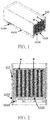
- FIG. 1 is a diagram of an additive manufacturing chamber 111 according to an embodiment of the present application.
- FIG. 2 is a diagram illustrating powder discharging openings 1111 of the additive manufacturing chamber 111 according to the embodiment of the present application.
- the additive manufacturing chamber 111 for additive manufacturing which is adopted in an additive manufacturing apparatus for additive manufacturing, is shown in FIG.1 .
- a heating base 1113 is disposed inside the additive manufacturing chamber 111 and substantially at a center of a bottom portion of the additive manufacturing chamber 111.
- a manufacturing platform 1112 is disposed above the heating base 1113.
- a plurality of powder discharging openings 1111 are formed at a lower portion of at least one of side walls of the additive manufacturing chamber 111.
- One or two restraining members 1114 are disposed on each of two side walls of, specifically to each of the left and right side walls of, the additive manufacturing chamber 111.
- the restraining members 1114 can restrain the manufacturing platform 1112 and the heating base 1113 from moving downwards so that a space above the manufacturing platform 1112 does not communicate with the plurality of powder discharging openings 1111 to prevent powders A disposed in the space from discharging through the plurality of powder discharging openings 1111.
- the space above the manufacturing platform 1112 is allowed to communicate with the plurality of powder discharging openings 1111 so that the powders A in the space can be discharged by gravitation through the plurality of powder discharging openings 1111.
- FIG. 5 is a diagram illustrating the additive manufacturing chamber 111 finishing powder discharging according to the embodiment of the present application.
- the plurality of powder discharging openings 1111 can be horizontally oriented, but not limited to this.
- the powder discharging openings 1111 can be downwardly inclined and face towards an outside of the additive manufacturing chamber 111 for enhancing powder discharging effect.
- a vibrational unit 1115 for vibrating the powders A can be disposed in the additive manufacturing chamber 111 and, preferably, adjacent to the powder discharging opening 1111 at the bottom portion of the additive manufacturing chamber 111. Therefore, the downward powder discharging can be accelerated via vibration of the vibrational unit 1115.
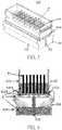
- FIG. 3 is a perspective diagram of an additive manufacturing module 110 according to an embodiment of the present application.
- the present application further provides the additive manufacturing module 110 which includes the additive manufacturing chamber 111, one or more first lifting units 112, and one or more first temporary storage troughs 113.
- the first lifting unit 112 is disposed below the additive manufacturing chamber 111 and for lifting and lowering the manufacturing platform 1112 and the heating base 1113.
- the first temporary storage trough 113 is disposed below the additive manufacturing chamber 111. It should be noticed that, in another embodiment of the present application, a plurality of first temporary storage troughs 113 can be disposed below the additive manufacturing chamber 111 and at two opposite sides (left and right sides) of the first lifting unit 112, but not limited to this.
- FIG. 4 is a diagram illustrating the additive manufacturing chamber 111 discharging the powders according to the embodiment of the present application.
- the first lifting unit 112 can lower the manufacturing platform 1112 and the heating base 1113 to a position lower than the plurality of powder discharging openings 1111, and thereby the space above the manufacturing platform 1112 communicates with the plurality of powder discharging openings 1111 so that the powders A in the space can be discharged by gravitation through the plurality of powder discharging openings 1111 into the first temporary storage trough 113 below.
- the powders A have all fallen into the first temporary storage trough 113, while work-pieces B still remain in the additive manufacturing chamber 111.
- FIG. 6 is a diagram illustrating configuration and operation of the restraining members 1114 according to the embodiment of the present application.
- most of the plurality of powder discharging openings 1111 are downwardly inclined and face towards an outside of the side walls of the additive manufacturing chamber 111 for enhancing the powder discharging effect, while the rest of the plurality of powder discharging openings 1111 are horizontally oriented so that the restraining members 1114 can be inserted into the horizontally oriented powder discharging openings 1111 and prevent the heating base 1113 and the manufacturing platform 1112 from moving downwards towards a position lower than the plurality of powder discharging openings 1111.
- the manufacturing platform 1112 and the heating base 1113 can be lowered to a position lower than the plurality of powder discharging openings 1111 so that the space above the manufacturing platform 1112 communicates with the plurality of powder discharging openings 1111 to discharge the powders in the space.
- the additive manufacturing chamber 111 or the additive manufacturing module 110 of the present application utilizes gravitation to discharge the powders down to the first temporary storage trough 113, which reduces consumed energy and swirled raised powder haze.
- FIG. 7 is a diagram of an additive manufacturing apparatus 1000 according to an embodiment of the present application.
- the present application further provides the additive manufacturing apparatus 1000 which includes a main system 1, and the main system 1 includes a controlling subsystem 13, an energy supplying subsystem 14, an environment modulating subsystem 12, and a fabrication subsystem 11.
- the fabrication subsystem 11 includes the additive manufacturing chamber 111, the first lifting unit 112, and the first temporary storage trough 113. It should be noticed that the additive manufacturing chamber 111, the first lifting unit 112, and the first temporary storage trough 113 compose the additive manufacturing module 110 of the previous embodiment.
- the energy supplying subsystem 13 supplies a high energy beam, such as a laser beam or an electronic beam, for sintering or fusing surfaces of the powders via a scanning heating process.
- the environment modulating subsystem 12 transports gas into the fabrication subsystem 11 and controls an atmosphere in the fabrication subsystem 11.
- the controlling subsystem 13 controls operations of the energy supplying subsystem 14, the environment modulating subsystem 12, and the fabrication subsystem 11.
- the embodiment of the additive manufacturing apparatus 1000 shown in FIG. 7 can be regarded as an independent additive manufacturing apparatus 1000.
- the first lifting unit 112 for lifting and lowering the manufacturing platform 1112 and the heating base 1113 in the additive manufacturing chamber 111 is disposed below the additive manufacturing chamber 111.
- the manufacturing platform 1112 and the heating base 1113 can be correspondingly lowered by the first lifting unit 112 but are prevented by the restraining members 1114 from moving downwards towards a position where a space above the manufacturing platform 112 communicates with the plurality of powder discharging openings 1111.
- the restraining members 1114 can be removed and the first lifting unit 112 of the fabrication subsystem 11 can lower the manufacturing platform 1112 and the heating base 1113 to a position lower than the plurality of powder discharging openings 1114 so that the space above the manufacturing platform 1112 communicates with the plurality of powder discharging openings 1114 for the powders in the space to be discharged by gravitation through the plurality of powder discharging openings 1111 down to the inside of the first temporary storage trough 113.
- the work-pieces B can be drawn out of the additive manufacturing chamber 111.
- FIG. 8 is a diagram of an additive manufacturing apparatus 1000' according to another embodiment of the present application.
- the manufacturing system 1 includes the main system 1 and the cleaning transportation system 2, and the cleaning transportation system 2 is separated from the main system 1.
- the main system 1 includes the controlling subsystem 13, the energy supplying subsystem 14, the environment modulating subsystem 12, and the fabrication subsystem 11. Since the controlling subsystem 13, the energy supplying subsystem 14 and the environment modulating subsystem 12 of this embodiment have the same structural designs and operational principles as ones of the previous embodiment, detailed description thereof is omitted here for simplicity.
- the fabrication system 11 of this embodiment includes the additive manufacturing chamber 111 and the first lifting unit 112 disposed below the additive manufacturing chamber 111 and for lifting and lowering the manufacturing platform 1112 and the heating base 1113. It should be noticed that the fabrication subsystem 11 can further include the first temporary storage trough 113 disposed below the additive manufacturing chamber 111 and for containing the discharged powders, but not limited to this.
- the cleaning transportation system 2 includes a work-piece transporting subsystem 22 and a cleaning subsystem 21, and the work-piece transporting subsystem 22 includes a transportation module 221.
- the transportation module 221 is for transporting the additive manufacturing chamber 111 from the fabrication subsystem 11 to the cleaning subsystem 21 (and vice versa).
- the cleaning subsystem 21 includes a cleaning hanging module 211, a second lifting unit 212, and a second temporary storage trough 213. After finishing the additive manufacturing, the transportation module 221 can transport the additive manufacturing chamber 111 from the fabrication subsystem 11 to the cleaning subsystem 21, and then the additive manufacturing chamber 111 can be supported by the second lifting unit 212 of the cleaning subsystem 21.
- the transported additive manufacturing chamber 111 can be supported by the second lifting unit 212 below the transported additive manufacturing chamber 111.
- the second temporary storage trough 213 is disposed below the transported additive manufacturing chamber 111.
- a plurality of second temporary storage troughs 213 can be disposed below the additive manufacturing chamber 111 and at two opposite sides (left and right sides) of the second lifting unit 212, but not limited to this.
- the second lifting unit 212 can lower or lift the manufacturing platform 1112 and the heating base 1113 of the additive manufacturing chamber 111.
- the second lifting unit 212 can lower the manufacturing platform 1112 and the heating base 1113 to a position where the space above the manufacturing platform 1112 communicates with the plurality of powder discharging openings 1111 so that the powders in the space can be discharged from the additive manufacturing chamber 111 down to the inside of the second temporary storage trough 213 below.
- the cleaning hanging module 211 cleans the work-pieces B in the additive manufacturing chamber 111 by hanging and rotating the additively manufactured work-pieces B.
- the cleaning hanging module 211 can separate the powders adhering to the work-pieces B via gravitation by hanging and rotating the work-pieces B, but not limited to this.
- one or more cleaning devices such as vacuum cleaners, brushes, pneumatic gun or air blowing guns, can be disposed in the cleaning hanging module 211 for removing the powders adhering to the work-pieces B.
- the additive manufacturing chamber 111 when the additive manufacturing chamber 111 is being transported by the transportation module 221 from the fabrication subsystem 11 to the cleaning subsystem 21 and disposed onto the second lifting unit 212 after finishing the additive manufacturing, the downward movements of the heating base 1113 and the manufacturing platform 1112 are restrained by the restraining members 1114 so that the space above the manufacturing platform 1112 does not communicate with the plurality of powder discharging openings 1111. Thereby, the powders can be prevented from swirling and leaking out of the additive manufacturing chamber 111 when the powders are not yet to be discharged.
- the additive manufacturing chamber, the additive manufacturing module, and the additive manufacturing apparatus utilizes gravitation to efficiently discharge down the remainder powders in the additive manufacturing chamber and to separate the powders from the finished work-pieces made by additive manufacturing, which solves the conventional problems of excessive consumed energy, large required installation and operational space, inconvenience of powder removing and swirled raised powder haze in the environment, and the complicated cleaning task after the additive manufacturing.
- the work-pieces of the present application can be remained in the additive manufacturing chamber and directly transported to a next work step during and after finishing the powder removing process, possible damages to the work-pieces in a conventional cleaning process due to delivery of the work-pieces can be avoided.
- the additive manufacturing chamber requires less structural components and provides better manufacturing and operational features. Therefore, the present application not only has an advantage of versatility but also reduces costs in additive manufacturing procedure, equipment, time and manpower.
Landscapes
- Engineering & Computer Science (AREA)
- Chemical & Material Sciences (AREA)
- Materials Engineering (AREA)
- Manufacturing & Machinery (AREA)
- Optics & Photonics (AREA)
- Physics & Mathematics (AREA)
- Mechanical Engineering (AREA)
- Life Sciences & Earth Sciences (AREA)
- Sustainable Development (AREA)
- Powder Metallurgy (AREA)
- Health & Medical Sciences (AREA)
- Toxicology (AREA)
- Environmental & Geological Engineering (AREA)
Applications Claiming Priority (1)
| Application Number | Priority Date | Filing Date | Title |
|---|---|---|---|
| TW106139392A TWI640418B (zh) | 2017-11-15 | 2017-11-15 | 積層製造加工槽及其積層製造設備 |
Publications (2)
| Publication Number | Publication Date |
|---|---|
| EP3486007A1 true EP3486007A1 (de) | 2019-05-22 |
| EP3486007B1 EP3486007B1 (de) | 2020-05-13 |
Family
ID=65034229
Family Applications (1)
| Application Number | Title | Priority Date | Filing Date |
|---|---|---|---|
| EP18204490.9A Active EP3486007B1 (de) | 2017-11-15 | 2018-11-06 | Kammer zur generativen fertigung, modul zur generativen fertigung und vorrichtung zur generativen fertigung damit |
Country Status (3)
| Country | Link |
|---|---|
| US (1) | US10814556B2 (de) |
| EP (1) | EP3486007B1 (de) |
| TW (1) | TWI640418B (de) |
Cited By (5)
| Publication number | Priority date | Publication date | Assignee | Title |
|---|---|---|---|---|
| CN110181048A (zh) * | 2019-05-24 | 2019-08-30 | 清华大学 | 一种钼基合金粉末的电子束增材制造方法 |
| CN111730027A (zh) * | 2020-05-06 | 2020-10-02 | 铜车马动力科技(宁波)有限公司 | 基于物联网的新能源汽车动力总成加工流水线 |
| CN111791493A (zh) * | 2020-06-29 | 2020-10-20 | 共享智能铸造产业创新中心有限公司 | 3d打印设备用液料循环利用系统 |
| EP4196303B1 (de) * | 2020-08-14 | 2024-03-13 | 3D Systems, Inc. | System und verfahren zur effizienten entfernung von nichtfusioniertem pulver in schüttgutform |
| US12330373B2 (en) | 2020-10-29 | 2025-06-17 | Peridot Print Llc | Build cake drop height determination |
Families Citing this family (19)
| Publication number | Priority date | Publication date | Assignee | Title |
|---|---|---|---|---|
| WO2017194144A1 (en) * | 2016-05-12 | 2017-11-16 | Hewlett-Packard Development Company, L.P. | Container for 3d printed objects and method of cooling and unpacking a manufactured object from a 3d printer using that container |
| WO2018022002A1 (en) | 2016-07-26 | 2018-02-01 | Hewlett-Packard Development Company, L.P. | Cooling of build material in 3d printing system |
| EP3658303B1 (de) * | 2017-07-26 | 2024-04-03 | Solventum Intellectual Properties Company | Verfahren zur herstellung eines physischen objekts durch generative fertigung |
| WO2019157127A1 (en) * | 2018-02-07 | 2019-08-15 | Desktop Metal, Inc. | Apparatus and method for additive manufacturing |
| US20210162668A1 (en) * | 2018-07-03 | 2021-06-03 | Freemelt Ab | Powder compartment with self-sealing design |
| US11084208B2 (en) * | 2018-10-17 | 2021-08-10 | General Electric Company | Additive manufacturing systems and methods including louvered particulate containment wall |
| CN110153423B (zh) * | 2019-06-20 | 2021-08-20 | 河北敬业增材制造科技有限公司 | 一种工业级金属3d打印机 |
| US11951515B2 (en) | 2019-08-05 | 2024-04-09 | Desktop Metal, Inc. | Techniques for depowdering additively fabricated parts via gas flow and related systems and methods |
| US11833585B2 (en) | 2019-08-12 | 2023-12-05 | Desktop Metal, Inc. | Techniques for depowdering additively fabricated parts through vibratory motion and related systems and methods |
| WO2021048733A1 (en) | 2019-09-12 | 2021-03-18 | 3M Innovative Properties Company | Apparatus, system, method of post-curing an article, and post-cured article |
| JP7327891B2 (ja) * | 2019-11-11 | 2023-08-16 | ダイハツ工業株式会社 | 積層造形方法及び積層造形装置 |
| JP7362433B2 (ja) * | 2019-11-11 | 2023-10-17 | ダイハツ工業株式会社 | 積層造形方法 |
| US11865615B2 (en) | 2019-12-11 | 2024-01-09 | Desktop Metal, Inc. | Techniques for depowdering additively fabricated parts and related systems and methods |
| CN111054921A (zh) * | 2020-01-06 | 2020-04-24 | 张武军 | 一种用于金属粉末打印的主动式防堵料盒 |
| CN111359881B (zh) * | 2020-04-02 | 2022-05-17 | 贵州省冶金化工研究所 | 一种3d打印后处理多级粒料分离系统及其分离方法 |
| JP7814325B2 (ja) * | 2020-05-27 | 2026-02-16 | シューラット テクノロジーズ,インク. | 積層製造のためのモジュール構成 |
| DE102020132663A1 (de) * | 2020-12-08 | 2022-06-09 | R. Scheuchl Gmbh | Einrichtung zur Entnahme eines mittels additiver Herstellung hergestellten Körpers |
| CN112917902B (zh) * | 2021-02-01 | 2022-05-06 | 青岛大学 | 一种fdm桌面级3d打印机底板结构 |
| CN115026312B (zh) * | 2022-06-24 | 2023-10-31 | 河南科技大学 | 一种激光立体成形工作台 |
Citations (5)
| Publication number | Priority date | Publication date | Assignee | Title |
|---|---|---|---|---|
| US20040084814A1 (en) * | 2002-10-31 | 2004-05-06 | Boyd Melissa D. | Powder removal system for three-dimensional object fabricator |
| US20120211155A1 (en) * | 2009-08-25 | 2012-08-23 | Bego Medical Gmbh | Device and Method for Generative Production |
| US20160067781A1 (en) * | 2014-09-05 | 2016-03-10 | Sodick Co., Ltd. | Three dimensional printer |
| US20160318253A1 (en) * | 2015-04-28 | 2016-11-03 | General Electric Company | Additive manufacturing apparatus and method |
| US20170136543A1 (en) * | 2015-11-13 | 2017-05-18 | SLM Solutions Group AG | Unpacking device allowing residual raw material powder removal |
Family Cites Families (3)
| Publication number | Priority date | Publication date | Assignee | Title |
|---|---|---|---|---|
| US10486950B2 (en) * | 2014-07-16 | 2019-11-26 | Gray Manufacturing Company, Inc. | Down stop indicator for vehicle lift |
| TW201617194A (zh) * | 2014-11-07 | 2016-05-16 | 國立成功大學 | 3d列印粉末回收機構 |
| US20200061915A1 (en) * | 2017-05-04 | 2020-02-27 | Eos Gmbh Electro Optical Systems | Interchangeable chamber for a device and a method for the additive manufacturing of a three-dimensional object |
-
2017
- 2017-11-15 TW TW106139392A patent/TWI640418B/zh active
-
2018
- 2018-10-21 US US16/166,134 patent/US10814556B2/en active Active
- 2018-11-06 EP EP18204490.9A patent/EP3486007B1/de active Active
Patent Citations (5)
| Publication number | Priority date | Publication date | Assignee | Title |
|---|---|---|---|---|
| US20040084814A1 (en) * | 2002-10-31 | 2004-05-06 | Boyd Melissa D. | Powder removal system for three-dimensional object fabricator |
| US20120211155A1 (en) * | 2009-08-25 | 2012-08-23 | Bego Medical Gmbh | Device and Method for Generative Production |
| US20160067781A1 (en) * | 2014-09-05 | 2016-03-10 | Sodick Co., Ltd. | Three dimensional printer |
| US20160318253A1 (en) * | 2015-04-28 | 2016-11-03 | General Electric Company | Additive manufacturing apparatus and method |
| US20170136543A1 (en) * | 2015-11-13 | 2017-05-18 | SLM Solutions Group AG | Unpacking device allowing residual raw material powder removal |
Cited By (5)
| Publication number | Priority date | Publication date | Assignee | Title |
|---|---|---|---|---|
| CN110181048A (zh) * | 2019-05-24 | 2019-08-30 | 清华大学 | 一种钼基合金粉末的电子束增材制造方法 |
| CN111730027A (zh) * | 2020-05-06 | 2020-10-02 | 铜车马动力科技(宁波)有限公司 | 基于物联网的新能源汽车动力总成加工流水线 |
| CN111791493A (zh) * | 2020-06-29 | 2020-10-20 | 共享智能铸造产业创新中心有限公司 | 3d打印设备用液料循环利用系统 |
| EP4196303B1 (de) * | 2020-08-14 | 2024-03-13 | 3D Systems, Inc. | System und verfahren zur effizienten entfernung von nichtfusioniertem pulver in schüttgutform |
| US12330373B2 (en) | 2020-10-29 | 2025-06-17 | Peridot Print Llc | Build cake drop height determination |
Also Published As
| Publication number | Publication date |
|---|---|
| US10814556B2 (en) | 2020-10-27 |
| TW201922465A (zh) | 2019-06-16 |
| EP3486007B1 (de) | 2020-05-13 |
| US20190143597A1 (en) | 2019-05-16 |
| TWI640418B (zh) | 2018-11-11 |
Similar Documents
| Publication | Publication Date | Title |
|---|---|---|
| EP3486007B1 (de) | Kammer zur generativen fertigung, modul zur generativen fertigung und vorrichtung zur generativen fertigung damit | |
| US10543643B2 (en) | Automated de-powdering via liquid immersion | |
| KR101988687B1 (ko) | 와이어 스태커 | |
| CN110510371B (zh) | 一种电感自动上料机 | |
| CN106864857B (zh) | 一种粉料的自动进料系统 | |
| JPH06154582A (ja) | 粉体の充填および回収装置 | |
| JP3597920B2 (ja) | 粉体塗料供給装置 | |
| CN1028688C (zh) | 阴极射线管石墨涂覆方法和设备 | |
| CN119255878A (zh) | 增材制造设施 | |
| CN119460723B (zh) | 自动装盘机 | |
| JP2819083B2 (ja) | ワーク取扱装置 | |
| JP3090870B2 (ja) | パッキンの自動組付装置 | |
| CN223476862U (zh) | 减振器阀座组件装配线 | |
| CN113859901B (zh) | 电池烘烤线 | |
| US10627809B2 (en) | Multilevel fabricators | |
| CN223476861U (zh) | 减振器连杆组件装配线 | |
| CN203910766U (zh) | 风动缓冲装置 | |
| KR102594536B1 (ko) | 트레이피더 | |
| CN219649763U (zh) | 用于光学器件的组装装置 | |
| CN119703741A (zh) | 减振器连杆组件装配方法 | |
| CN222971649U (zh) | 一种铝管切割机的下料装置 | |
| CN209970784U (zh) | 一种用于手套箱的自动卸料机构 | |
| CN111422620B (zh) | 一种旋转混合搬运系统及其搬运方法 | |
| CN115111974A (zh) | 一种自动化延期管压药线 | |
| JPH0516980A (ja) | 部品整列装置 |
Legal Events
| Date | Code | Title | Description |
|---|---|---|---|
| PUAI | Public reference made under article 153(3) epc to a published international application that has entered the european phase |
Free format text: ORIGINAL CODE: 0009012 |
|
| STAA | Information on the status of an ep patent application or granted ep patent |
Free format text: STATUS: THE APPLICATION HAS BEEN PUBLISHED |
|
| AK | Designated contracting states |
Kind code of ref document: A1 Designated state(s): AL AT BE BG CH CY CZ DE DK EE ES FI FR GB GR HR HU IE IS IT LI LT LU LV MC MK MT NL NO PL PT RO RS SE SI SK SM TR |
|
| AX | Request for extension of the european patent |
Extension state: BA ME |
|
| STAA | Information on the status of an ep patent application or granted ep patent |
Free format text: STATUS: REQUEST FOR EXAMINATION WAS MADE |
|
| 17P | Request for examination filed |
Effective date: 20190621 |
|
| RBV | Designated contracting states (corrected) |
Designated state(s): AL AT BE BG CH CY CZ DE DK EE ES FI FR GB GR HR HU IE IS IT LI LT LU LV MC MK MT NL NO PL PT RO RS SE SI SK SM TR |
|
| GRAP | Despatch of communication of intention to grant a patent |
Free format text: ORIGINAL CODE: EPIDOSNIGR1 |
|
| STAA | Information on the status of an ep patent application or granted ep patent |
Free format text: STATUS: GRANT OF PATENT IS INTENDED |
|
| INTG | Intention to grant announced |
Effective date: 20200110 |
|
| GRAS | Grant fee paid |
Free format text: ORIGINAL CODE: EPIDOSNIGR3 |
|
| GRAA | (expected) grant |
Free format text: ORIGINAL CODE: 0009210 |
|
| STAA | Information on the status of an ep patent application or granted ep patent |
Free format text: STATUS: THE PATENT HAS BEEN GRANTED |
|
| AK | Designated contracting states |
Kind code of ref document: B1 Designated state(s): AL AT BE BG CH CY CZ DE DK EE ES FI FR GB GR HR HU IE IS IT LI LT LU LV MC MK MT NL NO PL PT RO RS SE SI SK SM TR |
|
| REG | Reference to a national code |
Ref country code: GB Ref legal event code: FG4D |
|
| REG | Reference to a national code |
Ref country code: CH Ref legal event code: EP |
|
| REG | Reference to a national code |
Ref country code: DE Ref legal event code: R096 Ref document number: 602018004610 Country of ref document: DE |
|
| REG | Reference to a national code |
Ref country code: AT Ref legal event code: REF Ref document number: 1269601 Country of ref document: AT Kind code of ref document: T Effective date: 20200615 |
|
| REG | Reference to a national code |
Ref country code: LT Ref legal event code: MG4D |
|
| REG | Reference to a national code |
Ref country code: NL Ref legal event code: MP Effective date: 20200513 |
|
| PG25 | Lapsed in a contracting state [announced via postgrant information from national office to epo] |
Ref country code: NO Free format text: LAPSE BECAUSE OF FAILURE TO SUBMIT A TRANSLATION OF THE DESCRIPTION OR TO PAY THE FEE WITHIN THE PRESCRIBED TIME-LIMIT Effective date: 20200813 Ref country code: GR Free format text: LAPSE BECAUSE OF FAILURE TO SUBMIT A TRANSLATION OF THE DESCRIPTION OR TO PAY THE FEE WITHIN THE PRESCRIBED TIME-LIMIT Effective date: 20200814 Ref country code: SE Free format text: LAPSE BECAUSE OF FAILURE TO SUBMIT A TRANSLATION OF THE DESCRIPTION OR TO PAY THE FEE WITHIN THE PRESCRIBED TIME-LIMIT Effective date: 20200513 Ref country code: PT Free format text: LAPSE BECAUSE OF FAILURE TO SUBMIT A TRANSLATION OF THE DESCRIPTION OR TO PAY THE FEE WITHIN THE PRESCRIBED TIME-LIMIT Effective date: 20200914 Ref country code: FI Free format text: LAPSE BECAUSE OF FAILURE TO SUBMIT A TRANSLATION OF THE DESCRIPTION OR TO PAY THE FEE WITHIN THE PRESCRIBED TIME-LIMIT Effective date: 20200513 Ref country code: IS Free format text: LAPSE BECAUSE OF FAILURE TO SUBMIT A TRANSLATION OF THE DESCRIPTION OR TO PAY THE FEE WITHIN THE PRESCRIBED TIME-LIMIT Effective date: 20200913 Ref country code: LT Free format text: LAPSE BECAUSE OF FAILURE TO SUBMIT A TRANSLATION OF THE DESCRIPTION OR TO PAY THE FEE WITHIN THE PRESCRIBED TIME-LIMIT Effective date: 20200513 |
|
| PG25 | Lapsed in a contracting state [announced via postgrant information from national office to epo] |
Ref country code: HR Free format text: LAPSE BECAUSE OF FAILURE TO SUBMIT A TRANSLATION OF THE DESCRIPTION OR TO PAY THE FEE WITHIN THE PRESCRIBED TIME-LIMIT Effective date: 20200513 Ref country code: LV Free format text: LAPSE BECAUSE OF FAILURE TO SUBMIT A TRANSLATION OF THE DESCRIPTION OR TO PAY THE FEE WITHIN THE PRESCRIBED TIME-LIMIT Effective date: 20200513 Ref country code: BG Free format text: LAPSE BECAUSE OF FAILURE TO SUBMIT A TRANSLATION OF THE DESCRIPTION OR TO PAY THE FEE WITHIN THE PRESCRIBED TIME-LIMIT Effective date: 20200813 Ref country code: RS Free format text: LAPSE BECAUSE OF FAILURE TO SUBMIT A TRANSLATION OF THE DESCRIPTION OR TO PAY THE FEE WITHIN THE PRESCRIBED TIME-LIMIT Effective date: 20200513 |
|
| REG | Reference to a national code |
Ref country code: AT Ref legal event code: MK05 Ref document number: 1269601 Country of ref document: AT Kind code of ref document: T Effective date: 20200513 |
|
| PG25 | Lapsed in a contracting state [announced via postgrant information from national office to epo] |
Ref country code: AL Free format text: LAPSE BECAUSE OF FAILURE TO SUBMIT A TRANSLATION OF THE DESCRIPTION OR TO PAY THE FEE WITHIN THE PRESCRIBED TIME-LIMIT Effective date: 20200513 Ref country code: NL Free format text: LAPSE BECAUSE OF FAILURE TO SUBMIT A TRANSLATION OF THE DESCRIPTION OR TO PAY THE FEE WITHIN THE PRESCRIBED TIME-LIMIT Effective date: 20200513 |
|
| PG25 | Lapsed in a contracting state [announced via postgrant information from national office to epo] |
Ref country code: CZ Free format text: LAPSE BECAUSE OF FAILURE TO SUBMIT A TRANSLATION OF THE DESCRIPTION OR TO PAY THE FEE WITHIN THE PRESCRIBED TIME-LIMIT Effective date: 20200513 Ref country code: RO Free format text: LAPSE BECAUSE OF FAILURE TO SUBMIT A TRANSLATION OF THE DESCRIPTION OR TO PAY THE FEE WITHIN THE PRESCRIBED TIME-LIMIT Effective date: 20200513 Ref country code: IT Free format text: LAPSE BECAUSE OF FAILURE TO SUBMIT A TRANSLATION OF THE DESCRIPTION OR TO PAY THE FEE WITHIN THE PRESCRIBED TIME-LIMIT Effective date: 20200513 Ref country code: AT Free format text: LAPSE BECAUSE OF FAILURE TO SUBMIT A TRANSLATION OF THE DESCRIPTION OR TO PAY THE FEE WITHIN THE PRESCRIBED TIME-LIMIT Effective date: 20200513 Ref country code: DK Free format text: LAPSE BECAUSE OF FAILURE TO SUBMIT A TRANSLATION OF THE DESCRIPTION OR TO PAY THE FEE WITHIN THE PRESCRIBED TIME-LIMIT Effective date: 20200513 Ref country code: EE Free format text: LAPSE BECAUSE OF FAILURE TO SUBMIT A TRANSLATION OF THE DESCRIPTION OR TO PAY THE FEE WITHIN THE PRESCRIBED TIME-LIMIT Effective date: 20200513 Ref country code: SM Free format text: LAPSE BECAUSE OF FAILURE TO SUBMIT A TRANSLATION OF THE DESCRIPTION OR TO PAY THE FEE WITHIN THE PRESCRIBED TIME-LIMIT Effective date: 20200513 Ref country code: ES Free format text: LAPSE BECAUSE OF FAILURE TO SUBMIT A TRANSLATION OF THE DESCRIPTION OR TO PAY THE FEE WITHIN THE PRESCRIBED TIME-LIMIT Effective date: 20200513 |
|
| REG | Reference to a national code |
Ref country code: DE Ref legal event code: R097 Ref document number: 602018004610 Country of ref document: DE |
|
| PG25 | Lapsed in a contracting state [announced via postgrant information from national office to epo] |
Ref country code: SK Free format text: LAPSE BECAUSE OF FAILURE TO SUBMIT A TRANSLATION OF THE DESCRIPTION OR TO PAY THE FEE WITHIN THE PRESCRIBED TIME-LIMIT Effective date: 20200513 Ref country code: PL Free format text: LAPSE BECAUSE OF FAILURE TO SUBMIT A TRANSLATION OF THE DESCRIPTION OR TO PAY THE FEE WITHIN THE PRESCRIBED TIME-LIMIT Effective date: 20200513 |
|
| PLBE | No opposition filed within time limit |
Free format text: ORIGINAL CODE: 0009261 |
|
| STAA | Information on the status of an ep patent application or granted ep patent |
Free format text: STATUS: NO OPPOSITION FILED WITHIN TIME LIMIT |
|
| 26N | No opposition filed |
Effective date: 20210216 |
|
| PG25 | Lapsed in a contracting state [announced via postgrant information from national office to epo] |
Ref country code: SI Free format text: LAPSE BECAUSE OF FAILURE TO SUBMIT A TRANSLATION OF THE DESCRIPTION OR TO PAY THE FEE WITHIN THE PRESCRIBED TIME-LIMIT Effective date: 20200513 |
|
| PG25 | Lapsed in a contracting state [announced via postgrant information from national office to epo] |
Ref country code: MC Free format text: LAPSE BECAUSE OF FAILURE TO SUBMIT A TRANSLATION OF THE DESCRIPTION OR TO PAY THE FEE WITHIN THE PRESCRIBED TIME-LIMIT Effective date: 20200513 |
|
| PG25 | Lapsed in a contracting state [announced via postgrant information from national office to epo] |
Ref country code: LU Free format text: LAPSE BECAUSE OF NON-PAYMENT OF DUE FEES Effective date: 20201106 |
|
| REG | Reference to a national code |
Ref country code: BE Ref legal event code: MM Effective date: 20201130 |
|
| PG25 | Lapsed in a contracting state [announced via postgrant information from national office to epo] |
Ref country code: IE Free format text: LAPSE BECAUSE OF NON-PAYMENT OF DUE FEES Effective date: 20201106 |
|
| PG25 | Lapsed in a contracting state [announced via postgrant information from national office to epo] |
Ref country code: TR Free format text: LAPSE BECAUSE OF FAILURE TO SUBMIT A TRANSLATION OF THE DESCRIPTION OR TO PAY THE FEE WITHIN THE PRESCRIBED TIME-LIMIT Effective date: 20200513 Ref country code: MT Free format text: LAPSE BECAUSE OF FAILURE TO SUBMIT A TRANSLATION OF THE DESCRIPTION OR TO PAY THE FEE WITHIN THE PRESCRIBED TIME-LIMIT Effective date: 20200513 Ref country code: CY Free format text: LAPSE BECAUSE OF FAILURE TO SUBMIT A TRANSLATION OF THE DESCRIPTION OR TO PAY THE FEE WITHIN THE PRESCRIBED TIME-LIMIT Effective date: 20200513 |
|
| PG25 | Lapsed in a contracting state [announced via postgrant information from national office to epo] |
Ref country code: MK Free format text: LAPSE BECAUSE OF FAILURE TO SUBMIT A TRANSLATION OF THE DESCRIPTION OR TO PAY THE FEE WITHIN THE PRESCRIBED TIME-LIMIT Effective date: 20200513 |
|
| REG | Reference to a national code |
Ref country code: CH Ref legal event code: PL |
|
| PG25 | Lapsed in a contracting state [announced via postgrant information from national office to epo] |
Ref country code: BE Free format text: LAPSE BECAUSE OF NON-PAYMENT OF DUE FEES Effective date: 20201130 |
|
| PG25 | Lapsed in a contracting state [announced via postgrant information from national office to epo] |
Ref country code: LI Free format text: LAPSE BECAUSE OF NON-PAYMENT OF DUE FEES Effective date: 20211130 Ref country code: CH Free format text: LAPSE BECAUSE OF NON-PAYMENT OF DUE FEES Effective date: 20211130 |
|
| GBPC | Gb: european patent ceased through non-payment of renewal fee |
Effective date: 20221106 |
|
| PG25 | Lapsed in a contracting state [announced via postgrant information from national office to epo] |
Ref country code: GB Free format text: LAPSE BECAUSE OF NON-PAYMENT OF DUE FEES Effective date: 20221106 |
|
| REG | Reference to a national code |
Ref country code: DE Ref legal event code: R082 Ref document number: 602018004610 Country of ref document: DE Representative=s name: STRAUS, ALEXANDER, DIPL.-CHEM.UNIV. DR.PHIL., DE |
|
| PGFP | Annual fee paid to national office [announced via postgrant information from national office to epo] |
Ref country code: DE Payment date: 20251002 Year of fee payment: 8 |
|
| PGFP | Annual fee paid to national office [announced via postgrant information from national office to epo] |
Ref country code: FR Payment date: 20251001 Year of fee payment: 8 |