EP4196303B1 - System und verfahren zur effizienten entfernung von nichtfusioniertem pulver in schüttgutform - Google Patents
System und verfahren zur effizienten entfernung von nichtfusioniertem pulver in schüttgutform Download PDFInfo
- Publication number
- EP4196303B1 EP4196303B1 EP21840209.7A EP21840209A EP4196303B1 EP 4196303 B1 EP4196303 B1 EP 4196303B1 EP 21840209 A EP21840209 A EP 21840209A EP 4196303 B1 EP4196303 B1 EP 4196303B1
- Authority
- EP
- European Patent Office
- Prior art keywords
- build
- powder
- plate
- build box
- rotary frame
- Prior art date
- Legal status (The legal status is an assumption and is not a legal conclusion. Google has not performed a legal analysis and makes no representation as to the accuracy of the status listed.)
- Active
Links
Images


Classifications
-
- B—PERFORMING OPERATIONS; TRANSPORTING
- B22—CASTING; POWDER METALLURGY
- B22F—WORKING METALLIC POWDER; MANUFACTURE OF ARTICLES FROM METALLIC POWDER; MAKING METALLIC POWDER; APPARATUS OR DEVICES SPECIALLY ADAPTED FOR METALLIC POWDER
- B22F10/00—Additive manufacturing of workpieces or articles from metallic powder
- B22F10/60—Treatment of workpieces or articles after build-up
- B22F10/68—Cleaning or washing
-
- B—PERFORMING OPERATIONS; TRANSPORTING
- B22—CASTING; POWDER METALLURGY
- B22F—WORKING METALLIC POWDER; MANUFACTURE OF ARTICLES FROM METALLIC POWDER; MAKING METALLIC POWDER; APPARATUS OR DEVICES SPECIALLY ADAPTED FOR METALLIC POWDER
- B22F12/00—Apparatus or devices specially adapted for additive manufacturing; Auxiliary means for additive manufacturing; Combinations of additive manufacturing apparatus or devices with other processing apparatus or devices
- B22F12/22—Driving means
- B22F12/226—Driving means for rotary motion
-
- B—PERFORMING OPERATIONS; TRANSPORTING
- B08—CLEANING
- B08B—CLEANING IN GENERAL; PREVENTION OF FOULING IN GENERAL
- B08B7/00—Cleaning by methods not provided for in a single other subclass or a single group in this subclass
- B08B7/02—Cleaning by methods not provided for in a single other subclass or a single group in this subclass by distortion, beating, or vibration of the surface to be cleaned
-
- B—PERFORMING OPERATIONS; TRANSPORTING
- B22—CASTING; POWDER METALLURGY
- B22F—WORKING METALLIC POWDER; MANUFACTURE OF ARTICLES FROM METALLIC POWDER; MAKING METALLIC POWDER; APPARATUS OR DEVICES SPECIALLY ADAPTED FOR METALLIC POWDER
- B22F10/00—Additive manufacturing of workpieces or articles from metallic powder
- B22F10/20—Direct sintering or melting
- B22F10/28—Powder bed fusion, e.g. selective laser melting [SLM] or electron beam melting [EBM]
-
- B—PERFORMING OPERATIONS; TRANSPORTING
- B22—CASTING; POWDER METALLURGY
- B22F—WORKING METALLIC POWDER; MANUFACTURE OF ARTICLES FROM METALLIC POWDER; MAKING METALLIC POWDER; APPARATUS OR DEVICES SPECIALLY ADAPTED FOR METALLIC POWDER
- B22F12/00—Apparatus or devices specially adapted for additive manufacturing; Auxiliary means for additive manufacturing; Combinations of additive manufacturing apparatus or devices with other processing apparatus or devices
- B22F12/80—Plants, production lines or modules
- B22F12/82—Combination of additive manufacturing apparatus or devices with other processing apparatus or devices
- B22F12/86—Serial processing with multiple devices grouped
-
- B—PERFORMING OPERATIONS; TRANSPORTING
- B33—ADDITIVE MANUFACTURING TECHNOLOGY
- B33Y—ADDITIVE MANUFACTURING, i.e. MANUFACTURING OF THREE-DIMENSIONAL [3D] OBJECTS BY ADDITIVE DEPOSITION, ADDITIVE AGGLOMERATION OR ADDITIVE LAYERING, e.g. BY 3D PRINTING, STEREOLITHOGRAPHY OR SELECTIVE LASER SINTERING
- B33Y10/00—Processes of additive manufacturing
-
- B—PERFORMING OPERATIONS; TRANSPORTING
- B33—ADDITIVE MANUFACTURING TECHNOLOGY
- B33Y—ADDITIVE MANUFACTURING, i.e. MANUFACTURING OF THREE-DIMENSIONAL [3D] OBJECTS BY ADDITIVE DEPOSITION, ADDITIVE AGGLOMERATION OR ADDITIVE LAYERING, e.g. BY 3D PRINTING, STEREOLITHOGRAPHY OR SELECTIVE LASER SINTERING
- B33Y30/00—Apparatus for additive manufacturing; Details thereof or accessories therefor
-
- B—PERFORMING OPERATIONS; TRANSPORTING
- B33—ADDITIVE MANUFACTURING TECHNOLOGY
- B33Y—ADDITIVE MANUFACTURING, i.e. MANUFACTURING OF THREE-DIMENSIONAL [3D] OBJECTS BY ADDITIVE DEPOSITION, ADDITIVE AGGLOMERATION OR ADDITIVE LAYERING, e.g. BY 3D PRINTING, STEREOLITHOGRAPHY OR SELECTIVE LASER SINTERING
- B33Y40/00—Auxiliary operations or equipment, e.g. for material handling
- B33Y40/20—Post-treatment, e.g. curing, coating or polishing
-
- B—PERFORMING OPERATIONS; TRANSPORTING
- B22—CASTING; POWDER METALLURGY
- B22F—WORKING METALLIC POWDER; MANUFACTURE OF ARTICLES FROM METALLIC POWDER; MAKING METALLIC POWDER; APPARATUS OR DEVICES SPECIALLY ADAPTED FOR METALLIC POWDER
- B22F2998/00—Supplementary information concerning processes or compositions relating to powder metallurgy
-
- B—PERFORMING OPERATIONS; TRANSPORTING
- B22—CASTING; POWDER METALLURGY
- B22F—WORKING METALLIC POWDER; MANUFACTURE OF ARTICLES FROM METALLIC POWDER; MAKING METALLIC POWDER; APPARATUS OR DEVICES SPECIALLY ADAPTED FOR METALLIC POWDER
- B22F2999/00—Aspects linked to processes or compositions used in powder metallurgy
-
- Y—GENERAL TAGGING OF NEW TECHNOLOGICAL DEVELOPMENTS; GENERAL TAGGING OF CROSS-SECTIONAL TECHNOLOGIES SPANNING OVER SEVERAL SECTIONS OF THE IPC; TECHNICAL SUBJECTS COVERED BY FORMER USPC CROSS-REFERENCE ART COLLECTIONS [XRACs] AND DIGESTS
- Y02—TECHNOLOGIES OR APPLICATIONS FOR MITIGATION OR ADAPTATION AGAINST CLIMATE CHANGE
- Y02P—CLIMATE CHANGE MITIGATION TECHNOLOGIES IN THE PRODUCTION OR PROCESSING OF GOODS
- Y02P10/00—Technologies related to metal processing
- Y02P10/25—Process efficiency
Definitions
- the present invention concerns an apparatus and method for a layer-by-layer manufacture of three dimensional (3D) articles by selectively fusing or binding powder materials. More particularly, the present invention concerns a de-powdering system for efficiently removing unfused or unbound powder from build boxes that are generally too large and heavy for manual handling and lifting when filled with material.
- Three dimensional (3D) printing systems are in rapidly increasing use for purposes such as prototyping and manufacturing high value and/or customized articles.
- One type of three dimensional printer utilizes a layer-by-layer process to form a three dimensional article of manufacture from powdered materials.
- Each layer of powdered material is selectively fused using an energy beam such as a laser, electron, or particle beam or combined with a binder matrix.
- an energy beam such as a laser, electron, or particle beam or combined with a binder matrix.
- An energy beam such as a laser, electron, or particle beam or combined with a binder matrix.
- One challenge with such systems is an efficient and safe method for a removal of unfused or unbound powder after fabrication is complete.
- US 2016/279871 A discloses a device for unpacking a three-dimensional object, produced in an interchangeable container and/or on a construction platform by applying layers of a construction material in powder form and by selective hardening thereof, from the surrounding unhardened powder contains a rotating device for holding the interchangeable container and/or the construction platform, which rotating device is able to rotate the interchangeable container and/or the construction platform through an angle of at least 90° out of the upright position.
- EP 3167980 A discloses an unpacking device for use in an apparatus (10) for producing a three-dimensional work piece by irradiating layers of a raw material powder with electromagnetic or particle radiation, the unpacking device comprises a holding device which is configured to hold a building chamber arrangement.
- US 2018/215097 A provides an installation for cleaning a plate used in an additive manufacturing process performed using a powder.
- the installation includes an entry lock, an exit lock, a dry cleaner, a wet cleaner, and a conveyor system
- the invention provides an additive manufacturing system for producing a three-dimensional (3D) article according to claim 1.
- the disclosed system enables efficient and fully automated bulk removal of unfused powder from the 3D article. Operation of the clamps assures a very smooth rotation of the build box. Proper clamping is particularly important for a large metal powder build box due to an enormous weight of the 3D article and unfused powder. Having the agitation device mounted directly to the clamping plate maximizes a percentage of agitation energy that is transferred through the build plate to facilitate removal of powder with the least agitation energy.
- the print engine is configured to melt and fuse layers of the powder material using an energy beam.
- the energy beam can be a laser, an electron beam, or a particle beam.
- the transport mechanism transports the build box from the print engine to a cooling station.
- Step (1) includes transporting the build box from the cooling station to the internal receptacle cavity of the rotary frame.
- the plurality of clamps includes an upper clamp and at least one lateral clamp for clamping the build box along vertical and lateral axes during step (2).
- the lateral clamps can include lateral clamps that engage from opposing lateral directions. Providing clamping along multiple axes is advantageous when supporting and rotating a very heavy build box.
- the lift apparatus moves the clamp plate into clamping engagement with the build plate and then moves again to extract the build plate from the powder bin.
- This provides a vibration isolation between the build plate and the powder bin during operation of the agitation device.
- Wire ropes can provide vibration isolation between the build plate and the rotary frame.
- the vibration isolation reduces a requirement for a vibratory power level.
- the vibration isolation and reduced vibratory power level reduce NVH (noise, vibration, and harshness) which is advantageous for various reasons. This reduces vibratory damage to structural components of the manufacturing system including the build box, the rotary frame, and other components of the powder removal apparatus. This also reduces vibratory energy transfer to other components of the manufacturing system such as to the print engine.
- the powder deposition and beam system are both sensitive to vibrations.
- step 1) and (2) the rotary frame is in a rotative home position of zero degrees at which an open top of the build box faces upward.
- step (3) the rotary frame is rotated about 180 degrees from the home position about a central axis.
- the rotary frame rotates back and forth along a central axis to further facilitate unfused powder removal during step (4).
- the invention provides a method of manufacturing a 3D article according to claim 9.
- FIG. 1 is a schematic block diagram of an embodiment of an additive manufacturing (AM) system 2 for producing a three-dimensional (3D) article 100 ( FIG. 8H ).
- System 2 includes a plurality of components at least including a print engine 4, a cooling station 6, a bulk powder removal apparatus or station 8, a fine powder removal apparatus or station 10, a transport apparatus 12, a gas handling system 14, and a controller 16.
- the various components 4-14 can individually have separate "lower level" controllers for controlling their internal functions.
- a controller can function as a central controller.
- controller 16 will be considered to include all controllers that may reside externally or within the components 4-14. Controller 16 can be internal to AM system 2, external to AM system 2, or include portions that are both internal and external to AM system 2.
- the transport apparatus 12 is for transporting a build box 18 through the various components 4-10 in a sequence that includes fabricating, cooling, and de-powdering a 3D article being manufactured.
- the gas handling system 14 is for controlling an environment for components 4-10.
- the gas handling system is configured to evacuate components 4-10 and then to backfill them with a non-oxidizing gas such as argon or nitrogen in order to maintain the build box 18 within a non-oxidizing environment.
- Controller 16 includes a processor coupled to a non-transient or nonvolatile information storage device which stores software instructions. When executed by the processor, the software instructions operate any or all portions of the system 2. In an illustrative embodiment, fabrication, cooling, de-powdering, and other functions can be performed in a fully automated way by controller 16.
- Controller 16 is configured to perform steps such as (1) operate gas handling system 14 to evacuate and backfill components 4-10, (2) operate print engine 4 to fabricate a 3D article 100 in build box 18, (3) operate transport apparatus 12 to transport build box 18 (which now contains the 3D article and unfused powder) to the cooling station 6, (4) after an appropriate cooling time, operate transport apparatus to transport build box 18 to build powder removal station 8, (5) operate bulk powder removal apparatus 8 to remove most of the unfused powder from the build box 18, and (6) operate transport apparatus 12 to transport the build box 18 to the fine powder removal station 10. At the fine powder removal station 10, residual unfused powder is removed either automatically or manually. All the while, controller 16 operates the gas handling system 14 to maintain the non-oxidizing gaseous environment within the components 4-10 as required.
- AM system 2 can have other components such as an inspection station or a station for facilitating unloading of the 3D article 100 from the build box 18.
- the additional components can be manually operated or under control of controller 16.
- FIG. 2 is a schematic diagram of an embodiment of a 3D print engine 4.
- mutually orthogonal axes X, Y and Z can be used.
- Axes X and Y are lateral axes that are generally horizontal.
- Axis Z is a vertical axis that is generally aligned with a gravitational reference.
- general it is intended to be so by design but may vary due to manufacturing or other tolerances.
- the build box 18 includes a powder bin 20 containing a build plate 22.
- Build plate 22 has an upper surface 24 and is mechanically coupled to a vertical positioning system 26.
- the build box 18 is configured to contain dispensed metal powder (not shown).
- the build box 18 is contained within chamber 28 surrounded by housing 30.
- a metal powder dispenser 32 is configured to dispense layers of metal powder upon the upper surface 24 of the build plate 22 or on previously dispensed layers of metal.
- a second powder dispenser 34 is configured to dispense an additional powder such as another metal or a support material.
- Powder dispensers 32 and 34 are configured to receive powder from powder supplies 36 and 38 respectively.
- Print engine 4 includes a beam system 40 configured to generate a beam 42 for selectively fusing layers of dispensed metal powder.
- the beam system 40 includes a plurality of high power lasers for generating radiation beams individually having an optical power layer of at least 100 watts, at least 500 watts, or about 1000 watts or more.
- the beam system 40 can include optics for individually steering the radiation beams across a build plane that is coincident with an upper surface of a layer of metal powder.
- the beam system 40 can generate electron beams, particle beams, or a hybrid mixture of different beam types.
- the controller 16 can be configured to operate the print engine 4 to fabricate a 3D article: (1) operate the vertical positioning system 26 to position an upper surface 24 of build plate 26 or of a previously deposited layer of powder at one powder layer thickness below a build plane, (2) operate dispenser 32 to dispense a layer of metal powder on the upper surface 24, (3) operate the beam system to selectively fuse the just-dispensed layer of metal powder, and then repeat steps 1-3 to finish fabrication of the 3D article.
- the controller can also operate powder dispenser 34 and other components of print engine 4 as part of the fabrication.
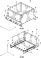
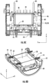
- FIGS. 3A and 3B are isometric views of an embodiment of a build box 18 which includes build plate 22 within powder bin 20.
- Powder bin 20 includes an open end 44 with upper clamp receivers 46 that extend from an end of powder bin 20 along the Y-axis.
- Powder bin 20 also has a pair of rails 48 with rollers 50 for transport within system 2. Rails 48 and rollers 50 extend along axis Y which is a direction of transport through the system 2.
- Y is a lateral transport direction and X is a transverse lateral direction.
- Four lateral clamp receivers 52 are at opposing ends (with respect to the Y-axis) of the powder bin 20 and face outwardly with respect to the X-axis.
- FIG. 4 is an isometric view of a portion of the build box 18 to put emphasis on latches 54 for securing the build plate 22 to the powder bin 20.
- the powder bin 20 includes four lower latches 54 that secure and provide a lower limit for the build plate 22 during the fabrication and cooling processes.
- the lower latches 54 individually have an upper surface 56 for engaging the build plate 22.
- the lower latches 54 individually are rotatively mounted about a hinge 58 having an axis of rotation parallel to the Y axis.
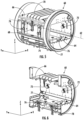
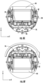
- FIG. 5 is an isometric view of a rotary frame 60 which is rotatively mounted within the bulk powder removal apparatus 8.
- Rotary frame 60 is configured to be rotated about a central axis 62 for up to a complete 360 degree rotation.
- the central axis 62 is parallel to Y and is at an approximate center of a circular cross-section of the rotary frame 60.
- Rotary frame 60 defines an internal receptacle cavity 64 for receiving the build box 18.
- the build box 18 is received into the internal receptacle cavity 64 along the Y axis.
- the orientation of the rotary frame 60 illustrated in FIG. 5 is a rotative "home" position for rotary frame 60.
- a rotation angle such as 90 degrees or 180 degrees refers to a clockwise rotation about central axis 62 from the home position.
- Rotary frame 60 includes an upper clamp 66 for engaging and clamping the open end 44 and upper clamp receivers 46 of the powder bin 20. Coupled between the upper clamp 66 and rotary frame 60 are actuators 68 for raising and lowering the upper clamp 66 along the vertical axis Z. Upper clamp 66 has an open top 70 to allow powder to exit at a rotation angles of about 180 degrees.
- FIG. 6 is a cutaway isometric view of the rotary frame 60.
- the axes X, Y, and Z have the same orientation for FIGS. 5 and 6 .
- Rotary frame 60 includes four lateral clamps 72 configured to extend and retract along the X-axis to engage and disengage the four lateral clamp receivers 52 of the powder bin 20. Coupled between the lateral clamps 72 and the rotary frame 60 are actuators 74 for extending and retracting the lateral clamp receivers 52 along the X-axis.
- Rotary frame 60 includes a clamping plate 76 configured to engage, clamp, and displace the build plate 22. Coupled between the clamping plate 76 and the rotary frame 60 is a lift apparatus 78 (see FIG. 8B , 8I for more views) for moving the clamping plate 76 into engagement with the build plate 22 and for extracting the build plate 22 from the powder bin 20.
- the clamping plate 76 includes one or more pneumatic chucks 77 for gripping portion(s) of the build plate 22.
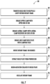
- FIG. 7 is a flowchart of an embodiment of a method 80 for removing bulk powder from the build box 18 using the bulk powder removal apparatus 8.
- Print engine 4 fabricated a 3D article 100 onto the upper surface 24 of build plate 22; unfused powder surrounds the 3D article above the upper surface and within the powder bin 20.
- the transport apparatus transported the build box 18 to the cooling station and time has elapsed for the contents of the build box 18 to cool.
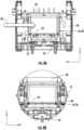
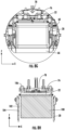
- FIG. 8A is a side cutaway YZ-view and FIG. 8B is a side cutaway XZ-view of the rotary frame 60 containing the build box 18 before any of the clamps (66, 72, 76) have engaged portions of the build box 18.
- clamps (66, 72, 76) are in their retracted state.
- FIG. 8C is a side cutaway through the YZ-plane illustrating step 84 (direction of motion indicated by block arrows 85).
- the upper clamp 66 then applies a vertical clamping force upon the build box 18.
- FIG. 8D is an isometric cutaway view illustrating step 86. After steps 84 and 86, the build box 18 is clamped and restrained vertically and laterally.
- FIG. 8E is a side cutaway view with a horizontal cut parallel to the X-plane illustrating step 88.
- the upward motion lifts the build plate 22 off of lower latches 54 and the build plate 22 is clamped with at least one pneumatic chuck 77 ( FIG. 6 ) that is part of the clamping plate 76.
- FIG. 8F is a side cutaway XZ-view illustrating step 90. Because the powder bin 20 is open at the end opposite to the build plate 22, a majority of the unfused powder will then fall vertically downward and into a capturing portion of the bulk powder removal apparatus 8 below the rotary frame 60. Also, in the inverted 180 degree position of the rotary frame 60, the latches 54 rotate inwardly so that the build plate 22 can be extracted in step 92.
- FIG. 8G is a side cutaway XZ-view illustrating step 92 with lift apparatus 78 lifting the clamping plate 76 and extracting the build plate 22.
- FIG. 8H is a side schematic cutaway view illustrating isolated parts including the 3D article 100 with attached unfused powder coupled to the build plate 22 which is in turn coupled to the clamping plate 76.
- the 3D article 100 has been fabricated with a clearance 102 between inside surfaces 104 of the powder bin 20 and the 3D article 100.
- FIG. 8I is an isometric view of the powder bin 20, the build plate 22, and the clamping plate 76.
- FIGS. 8G, 8H , and 8I all correspond to step 92 in which the build plate 22 has been extracted from the powder bin 20 and therefore the build plate 22 is mechanically isolated from the powder bin 20.
- Wire rope isolators 106 also mechanically couple the clamping plate 76 to the rotary frame 60.
- the clamping plate 76 is vibration isolated from the powder bin 20 and from the rotary frame 60.
- Two agitation devices 108 are mounted to the clamping plate 76.
- the agitation devices 108 individually contain a motor coupled to an eccentric weight.
- the motor has an axis of rotation aligned with the X-axis.
- the primary vibratory force direction is along the vertical Z axis (perpendicular to the upper surface 24 of the build plate).
- a secondary vibratory force direction is along the Y-axis which is parallel to the upper surface 24.
- one or both of the agitation devices 108 are activated to facilitate and enhance removal of the unfused powder. Because the build plate clamp is vibration isolated from the powder bin 20 and the rotary frame 60, nearly all of the vibratory energy is transmitted and utilized for removing powder with minimal wasted energy that would otherwise vibrate the powder bin 20 and/or the rotary frame 60.
- FIG. 8J illustrates this rocking rotational motion about central axis 62 ( FIG. 5 ).
- This rocking motion further facilitates and enhances removal of the unfused powder.
- the rocking motion would be about the Y axis for plus and minus 90 degrees from the position of FIG. 8G (or between 90 and 270 degrees from the position of FIG. 8B ).
Landscapes
- Engineering & Computer Science (AREA)
- Chemical & Material Sciences (AREA)
- Materials Engineering (AREA)
- Manufacturing & Machinery (AREA)
- Physics & Mathematics (AREA)
- Plasma & Fusion (AREA)
- Mechanical Engineering (AREA)
- Powder Metallurgy (AREA)
Claims (15)
- Additives Fertigungssystem zur Herstellung eines dreidimensionalen (3D) Artikels, umfassend:eine Druckmaschine (4), die so konfiguriert ist, dass sie den Artikel durch das Verschmelzen oder Verbinden von Pulvermaterial schichtweise herstellen kann;einen Baukasten (18), der einen Pulverbehälter (20) und eine Bauplatte (22) umfasst;eine Nachfertigungspulverentfernungsvorrichtung, umfassend:einen Drehrahmen (60), der einen internen Gefäßhohlraum (64) definiert;eine Vielzahl von Klammern (66, 72), die an eine entsprechende Vielzahl von Stellantrieben (68, 74) gekoppelt sind; undeine Klemmplatte (76), die an eine Hebevorrichtung (78) gekoppelt ist;eine Schüttelvorrichtung (108), die auf der Klemmplatte (76) montiert ist;einen Transportmechanismus; undein Steuerungsgerät (16), das so konfiguriert ist, dass es die folgenden Schritte durchführen kann:(1) den Transportmechanismus so betreiben, dass der Baukasten (18) zum internen Gefäßhohlraum (64) transportiert wird;(2) die Vielzahl von Stellantrieben so betreiben, dass der Baukasten (18) an der Vielzahl von Klammern angreift, um den Baukasten an dem Drehrahmen (60) zu befestigen;(3) den Drehrahmen so betreiben, dass sich der Baukasten (18) dreht, bis ungeschmolzenes Pulver beginnt, aus dem Baukasten (18) auszutreten; und(4) die Schüttelvorrichtung (108) so betreiben, dass das Schütten des ungeschmolzenen Pulvers aus dem Baukasten (18) erleichtert wird.
- Additives Fertigungssystem gemäß Anspruch 1, wobei die Druckmaschine (4) so konfiguriert ist, dass sie Schichten des Pulvermaterials mit der Wirkung eines Energiestrahls schmelzen und miteinander verschmelzen kann.
- Additives Fertigungssystem gemäß Anspruch 1, wobei vor Schritt (1) der Transportmechanismus den Baukasten (18) von der Druckmaschine (4) aus zu einer Kühlstation (6) transportiert und Schritt (1) einen Transport des Baukastens (18) von der Kühlstation (6) aus zum internen Gefäßhohlraum (64) umfasst.
- Additives Fertigungssystem gemäß Anspruch 1, wobei die Vielzahl von Klammern (66, 72) eine obere Klammer (66) zum vertikalen Einklemmen des Baukastens (18) in Schritt (2) umfasst oder wobei die Vielzahl von Klammern (66, 72) eine Vielzahl von seitlichen Klammern (72) zum horizontalen Einklemmen des Baukastens (18) während Schritt (2) umfasst oder wobei die Vielzahl von Klammern (66, 72) eine obere Klammer (66) und wenigstens eine seitliche Klammer (72) zum Einklemmen des Baukastens (18) entlang einer vertikalen und einer seitlichen Achse während Schritt (2) umfasst.
- Additives Fertigungssystem gemäß Anspruch 1, wobei die Hebevorrichtung (78) die Klemmplatte (76) so anhebt, dass die Klemmplatte (76) an der Bauplatte (22) angreift,wobei der Pulverbehälter (20) wenigstens eine Lasche (54) zur Befestigung der Bauplatte (22) an dem Pulverbehälter (20) umfasst, der Betrieb der Hebevorrichtung (78) die die wenigstens eine Lasche (54) löst oderwobei sich vor Schritt (4) die Hebevorrichtung (78) so bewegt, dass sie die Bauplatte (22) aus dem Pulverbehälter (20) herauszieht.
- Additives Fertigungssystem gemäß Anspruch 1, wobei sich während Schritt (1) und (2) der Drehrahmen (60) in einer rotativen Grundstellung von null Grad befindet, in der ein offener Oberteil des Baukastens (18) nach oben gewandt ist, und während Schritt (3) der Drehrahmen gegenüber der Grundstellung um 180 Grad um eine Mittelachse herum gedreht ist.
- Additives Fertigungssystem gemäß Anspruch 1, wobei das Schütteln in erster Linie entlang einer vertikalen Achse erfolgt.
- Additives Fertigungssystem gemäß Anspruch 1, wobei sich während Schritt (4) der Drehrahmen (60) um eine Mittelachse parallel zu einer Y-Achse herum vor und zurück dreht, um das Entfernen von ungeschmolzenem Pulver weiter zu erleichtern.
- Verfahren zur Herstellung eines 3D-Artikels, umfassend:
das Bereitstellen:einer Druckmaschine (4), die so konfiguriert ist, dass sie den Artikel durch das Verschmelzen oder Verbinden von Pulvermaterial schichtweise herstellen kann;eines Baukastens (18), der einen Pulverbehälter (20) und eine Bauplatte (22) umfasst;einer Nachfertigungspulverentfernungsvorrichtung, umfassend:einen Drehrahmen (60), der einen internen Gefäßhohlraum (64) definiert;eine Vielzahl von Klammern (66, 72), die an eine entsprechende Vielzahl von Stellantrieben (68, 74) gekoppelt sind; undeine Klemmplatte (76), die an eine Hebevorrichtung (78) gekoppelt ist;eine Schüttelvorrichtung (108), die auf der Klemmplatte (76) montiert ist;einen Transportmechanismus; und(1) das Betreiben des Transportmechanismus in einer Weise, dass der Baukasten (18) zum internen Gefäßhohlraum (64) transportiert wird;(2) das Betreiben der Vielzahl von Stellantrieben (68, 74) in einer Weise, dass der Baukasten (18) an der Vielzahl von Klammern (66, 72) angreift, um den Baukasten (18) an dem Drehrahmen (60) zu befestigen;(3) das Betreiben des Drehrahmens (60) in einer Weise, dass sich der Baukasten (18) dreht, bis ungeschmolzenes Pulver beginnt, aus dem Baukasten (18) auszutreten; und(4) das Betreiben der Schüttelvorrichtung (108) in einer Weise, dass das Schütten des ungeschmolzenen Pulvers aus dem Baukasten (18) erleichtert wird. - Verfahren gemäß Anspruch 9, wobei die Vielzahl von Klammern (66, 72) eine obere Klammer (66) zum vertikalen Einklemmen des Baukastens (18) in Schritt (2) umfasst.
- Verfahren gemäß Anspruch 9, wobei die Vielzahl von Klammern (66, 72) eine Vielzahl von seitlichen Klammern (72) zum horizontalen Einklemmen des Baukastens während Schritt (2) umfasst.
- Verfahren nach Anspruch 9, wobei nach Schritt (2), aber vor Schritt (3) die Hebevorrichtung (78) die Klemmplatte (76) so anhebt, dass die Klemmbauplatte (22) an der Klemmplatte (76) angreift.
- Verfahren gemäß Anspruch 12, wobei sich vor Schritt (4) die Hebevorrichtung (78) so bewegt, dass sie die Bauplatte (22) aus dem Pulverbehälter (20) herauszieht.
- Verfahren gemäß Anspruch 12, wobei vor Schritt (4) die Hebevorrichtung (78) die Klemmplatte (76) in einen Klemmangriff mit der Bauplatte (22) bewegt und sich dann wieder so bewegt, dass sie die Bauplatte (22) aus dem Pulverbehälter (20) herauszieht.
- Additives Fertigungssystem zur Herstellung eines dreidimensionalen (3D) Artikels gemäß Anspruch 1, wobei:
die Nachfertigungspulverentfernungsvorrichtung Folgendes umfasst:einen Drehrahmen (60), der einen internen Gefäßhohlraum (64) definiert;eine Vielzahl von Klammern (66, 72), einschließlich einer oberen Klammer (66) und wenigstens einer seitlichen Klammer (72), die Vielzahl von Klammern (66, 72) einzeln an einen Stellantrieb (68, 74) gekoppelt sind;eine Klemmplatte (76), die an eine Hebevorrichtung (78) gekoppelt ist; undeine Schüttelvorrichtung (108), die auf der Klemmplatte (76) montiert ist;und wobeidas Steuerungsgerät (16) so konfiguriert ist, dass es die folgenden Schritte durchführen kann:(1) das Betreiben des Transportmechanismus in einer Weise, dass der Baukasten (18) zum internen Gefäßhohlraum (64) transportiert wird;(2) das Betreiben der Vielzahl von Klammern (66, 72) in einer Weise, dass der Baukasten an dem Drehrahmen (60) befestigt wird;(3) das Betreiben der Hebevorrichtung (78) in einer Weise, dass die Klemmplatte (76) an der Bauplatte (22) angreift und daran geklemmt wird;(4) das Betreiben des Drehrahmens (60) in einer Weise, dass sich der Baukasten (18) dreht, damit ungeschmolzenes Pulver aus dem Baukasten (18) austreten kann;(5) das Betreiben der Hebevorrichtung (78) in einer Weise, dass sie die Bauplatte (76) aus dem Pulverbehälter (20) herauszieht;(6) das Betreiben der Schüttelvorrichtung (108) in einer Weise, dass die Bauplatte (22) geschüttelt wird und dadurch das Schütten des ungeschmolzenen Pulvers aus dem Baukasten (18) erleichtert wird; und(7) gleichzeitig mit dem Betreiben der Bauplattenhandhabungsvorrichtung das Schütteln der Bauplatte (76), das Betreiben des Drehrahmens (60) in einer Weise, dass der Baukasten (18) vor- und zurückschwingt, um das Entfernen von ungeschmolzenem Pulver weiter zu erleichtern.
Applications Claiming Priority (2)
| Application Number | Priority Date | Filing Date | Title |
|---|---|---|---|
| US202063065859P | 2020-08-14 | 2020-08-14 | |
| PCT/US2021/046081 WO2022036304A2 (en) | 2020-08-14 | 2021-08-16 | Efficient bulk unfused powder removal system and method |
Publications (2)
| Publication Number | Publication Date |
|---|---|
| EP4196303A2 EP4196303A2 (de) | 2023-06-21 |
| EP4196303B1 true EP4196303B1 (de) | 2024-03-13 |
Family
ID=79287636
Family Applications (1)
| Application Number | Title | Priority Date | Filing Date |
|---|---|---|---|
| EP21840209.7A Active EP4196303B1 (de) | 2020-08-14 | 2021-08-16 | System und verfahren zur effizienten entfernung von nichtfusioniertem pulver in schüttgutform |
Country Status (4)
| Country | Link |
|---|---|
| US (2) | US11597016B2 (de) |
| EP (1) | EP4196303B1 (de) |
| JP (1) | JP7549126B2 (de) |
| WO (1) | WO2022036304A2 (de) |
Families Citing this family (6)
| Publication number | Priority date | Publication date | Assignee | Title |
|---|---|---|---|---|
| WO2022093943A1 (en) * | 2020-10-29 | 2022-05-05 | General Electric Company | Additive manufacturing apparatuses with removable build boxes and lid management systems |
| CN115782174B (zh) * | 2022-11-25 | 2025-09-30 | 天津镭明激光科技有限公司 | 一种增材制造零件的自动清粉控制方法 |
| CN116021040B (zh) * | 2022-12-30 | 2025-05-06 | 苏州西帝摩三维打印科技有限公司 | 用于大型激光选区熔化设备的仓体交换装置 |
| US20240399461A1 (en) * | 2023-05-30 | 2024-12-05 | Spirit Aerosystems, Inc. | Method for three-dimensional printed powder containment |
| CN118180384A (zh) * | 2024-05-13 | 2024-06-14 | 百琪达智能科技(宁波)股份有限公司 | 一种全自动压机 |
| CN119634755A (zh) * | 2025-02-18 | 2025-03-18 | 沈阳飞驰电气设备有限公司 | 一种增材打印设备用成形缸体粉末清理装置 |
Citations (1)
| Publication number | Priority date | Publication date | Assignee | Title |
|---|---|---|---|---|
| EP3486007A1 (de) * | 2017-11-15 | 2019-05-22 | National Chung-Shan Institute of Science and Technology | Kammer zur generativen fertigung, modul zur generativen fertigung und vorrichtung zur generativen fertigung damit |
Family Cites Families (13)
| Publication number | Priority date | Publication date | Assignee | Title |
|---|---|---|---|---|
| US8601907B2 (en) * | 2004-09-24 | 2013-12-10 | Kai U.S.A., Ltd. | Knife blade manufacturing process |
| EP2874928B1 (de) * | 2012-07-19 | 2016-06-15 | Adamis Pharmaceuticals Corporation | Pulverzufuhrvorrichtung |
| DE102013223407A1 (de) | 2013-11-15 | 2015-05-21 | Eos Gmbh Electro Optical Systems | Vorrichtung und Verfahren zum schichtweisen Herstellen eines dreidimensionalen Objekts sowie zum Auspacken des fertiggestellten Objekts |
| JP6276091B2 (ja) * | 2014-03-31 | 2018-02-07 | 日本電子株式会社 | 3次元積層造形装置に用いられるブラスト装置 |
| US10011892B2 (en) * | 2014-08-21 | 2018-07-03 | Honeywell International Inc. | Methods for producing alloy forms from alloys containing one or more extremely reactive elements and for fabricating a component therefrom |
| DE102014112446A1 (de) * | 2014-08-29 | 2016-03-03 | Exone Gmbh | Verfahren und Vorrichtung zum Entpacken eines Bauteils |
| US9855704B2 (en) * | 2015-02-27 | 2018-01-02 | Technology Research Association For Future Additive Manufacturing | Powder recoater |
| FR3039438B1 (fr) | 2015-07-30 | 2017-08-18 | Michelin & Cie | Installation de nettoyage de plateaux de fabrication additive |
| EP3167980A1 (de) | 2015-11-13 | 2017-05-17 | SLM Solutions Group AG | Auspackvorrichtung mit beseitigung von rohmaterialrestpulver |
| US10189057B2 (en) * | 2016-07-08 | 2019-01-29 | General Electric Company | Powder removal enclosure for additively manufactured components |
| WO2018154283A1 (en) * | 2017-02-21 | 2018-08-30 | Renishaw Plc | Powder bed fusion apparatus and break-out device |
| US11484944B2 (en) * | 2019-02-11 | 2022-11-01 | 3D Systems, Inc. | Three-dimensional printer with two state filter for powdered metal |
| CN111497247A (zh) * | 2020-05-18 | 2020-08-07 | 东阳市俊康文具有限公司 | 一种3d打印的粉尘刷落装置 |
-
2021
- 2021-08-16 EP EP21840209.7A patent/EP4196303B1/de active Active
- 2021-08-16 JP JP2023508550A patent/JP7549126B2/ja active Active
- 2021-08-16 WO PCT/US2021/046081 patent/WO2022036304A2/en not_active Ceased
- 2021-08-16 US US17/402,811 patent/US11597016B2/en active Active
-
2023
- 2023-02-03 US US18/163,956 patent/US11794254B1/en active Active
Patent Citations (1)
| Publication number | Priority date | Publication date | Assignee | Title |
|---|---|---|---|---|
| EP3486007A1 (de) * | 2017-11-15 | 2019-05-22 | National Chung-Shan Institute of Science and Technology | Kammer zur generativen fertigung, modul zur generativen fertigung und vorrichtung zur generativen fertigung damit |
Also Published As
| Publication number | Publication date |
|---|---|
| US20220111443A1 (en) | 2022-04-14 |
| US11597016B2 (en) | 2023-03-07 |
| WO2022036304A3 (en) | 2022-03-24 |
| US20230364681A1 (en) | 2023-11-16 |
| WO2022036304A2 (en) | 2022-02-17 |
| EP4196303A2 (de) | 2023-06-21 |
| JP7549126B2 (ja) | 2024-09-10 |
| US11794254B1 (en) | 2023-10-24 |
| JP2023537920A (ja) | 2023-09-06 |
Similar Documents
| Publication | Publication Date | Title |
|---|---|---|
| EP4196303B1 (de) | System und verfahren zur effizienten entfernung von nichtfusioniertem pulver in schüttgutform | |
| US11691342B2 (en) | Powder bed fusion apparatus and methods | |
| JP6667521B2 (ja) | 複数の部材を同時に、生成的に製造するための生産設備 | |
| KR102476085B1 (ko) | 개선된 기판 스토리지 및 프로세싱 | |
| JP3790473B2 (ja) | 三次元物体の形成的製造のための装置および方法 | |
| CN108290180B (zh) | 增材制造系统和方法 | |
| KR101463473B1 (ko) | 이송 장치 | |
| CN104884206B (zh) | 通过升降圆台快速更换工具的机动车辆车身元件焊接方法和装置 | |
| CN108202994A (zh) | 用于添加式地制造三维物体的系统 | |
| KR20050044434A (ko) | 초소형전자 기판을 처리하는 감소의 풋프린트 공구 | |
| EP3687766B1 (de) | Hochleistungsvorrichtung zur schichtweisen herstellung aus pulverförmigen materialien | |
| CN105793975A (zh) | 具有底盘的净化室-运输容器 | |
| US20200156150A1 (en) | Object shaping system | |
| CN111655459A (zh) | 一种用于取出3d打印部件的方法 | |
| CN113206023B (zh) | 搬运管芯载具的装置、系统及方法 | |
| US20250303638A1 (en) | Additive manufacturing facility | |
| TW201921573A (zh) | 基片運送方法和裝置 | |
| DE202025107197U1 (de) | Planares Antriebssystem und Verwendung des planaren Antriebssystems | |
| JPH07240377A (ja) | 成膜装置の基板搬送装置 | |
| JPH0422532A (ja) | 型の製作方法および製作装置 |
Legal Events
| Date | Code | Title | Description |
|---|---|---|---|
| STAA | Information on the status of an ep patent application or granted ep patent |
Free format text: STATUS: UNKNOWN |
|
| STAA | Information on the status of an ep patent application or granted ep patent |
Free format text: STATUS: THE INTERNATIONAL PUBLICATION HAS BEEN MADE |
|
| PUAI | Public reference made under article 153(3) epc to a published international application that has entered the european phase |
Free format text: ORIGINAL CODE: 0009012 |
|
| STAA | Information on the status of an ep patent application or granted ep patent |
Free format text: STATUS: REQUEST FOR EXAMINATION WAS MADE |
|
| 17P | Request for examination filed |
Effective date: 20230117 |
|
| AK | Designated contracting states |
Kind code of ref document: A2 Designated state(s): AL AT BE BG CH CY CZ DE DK EE ES FI FR GB GR HR HU IE IS IT LI LT LU LV MC MK MT NL NO PL PT RO RS SE SI SK SM TR |
|
| GRAJ | Information related to disapproval of communication of intention to grant by the applicant or resumption of examination proceedings by the epo deleted |
Free format text: ORIGINAL CODE: EPIDOSDIGR1 |
|
| STAA | Information on the status of an ep patent application or granted ep patent |
Free format text: STATUS: GRANT OF PATENT IS INTENDED |
|
| DAV | Request for validation of the european patent (deleted) | ||
| DAX | Request for extension of the european patent (deleted) | ||
| GRAP | Despatch of communication of intention to grant a patent |
Free format text: ORIGINAL CODE: EPIDOSNIGR1 |
|
| RIC1 | Information provided on ipc code assigned before grant |
Ipc: B08B 7/02 20060101ALI20231103BHEP Ipc: B33Y 40/20 20200101ALI20231103BHEP Ipc: B22F 12/86 20210101ALI20231103BHEP Ipc: B22F 12/00 20210101ALI20231103BHEP Ipc: B08B 1/00 20060101ALI20231103BHEP Ipc: B22F 10/68 20210101AFI20231103BHEP |
|
| INTG | Intention to grant announced |
Effective date: 20231123 |
|
| P01 | Opt-out of the competence of the unified patent court (upc) registered |
Effective date: 20231130 |
|
| GRAS | Grant fee paid |
Free format text: ORIGINAL CODE: EPIDOSNIGR3 |
|
| GRAA | (expected) grant |
Free format text: ORIGINAL CODE: 0009210 |
|
| STAA | Information on the status of an ep patent application or granted ep patent |
Free format text: STATUS: THE PATENT HAS BEEN GRANTED |
|
| AK | Designated contracting states |
Kind code of ref document: B1 Designated state(s): AL AT BE BG CH CY CZ DE DK EE ES FI FR GB GR HR HU IE IS IT LI LT LU LV MC MK MT NL NO PL PT RO RS SE SI SK SM TR |
|
| REG | Reference to a national code |
Ref country code: GB Ref legal event code: FG4D |
|
| REG | Reference to a national code |
Ref country code: CH Ref legal event code: EP |
|
| REG | Reference to a national code |
Ref country code: DE Ref legal event code: R096 Ref document number: 602021010505 Country of ref document: DE |
|
| REG | Reference to a national code |
Ref country code: IE Ref legal event code: FG4D |
|
| PG25 | Lapsed in a contracting state [announced via postgrant information from national office to epo] |
Ref country code: LT Free format text: LAPSE BECAUSE OF FAILURE TO SUBMIT A TRANSLATION OF THE DESCRIPTION OR TO PAY THE FEE WITHIN THE PRESCRIBED TIME-LIMIT Effective date: 20240313 |
|
| REG | Reference to a national code |
Ref country code: LT Ref legal event code: MG9D |
|
| PG25 | Lapsed in a contracting state [announced via postgrant information from national office to epo] |
Ref country code: GR Free format text: LAPSE BECAUSE OF FAILURE TO SUBMIT A TRANSLATION OF THE DESCRIPTION OR TO PAY THE FEE WITHIN THE PRESCRIBED TIME-LIMIT Effective date: 20240614 |
|
| REG | Reference to a national code |
Ref country code: NL Ref legal event code: MP Effective date: 20240313 |
|
| PG25 | Lapsed in a contracting state [announced via postgrant information from national office to epo] |
Ref country code: HR Free format text: LAPSE BECAUSE OF FAILURE TO SUBMIT A TRANSLATION OF THE DESCRIPTION OR TO PAY THE FEE WITHIN THE PRESCRIBED TIME-LIMIT Effective date: 20240313 Ref country code: RS Free format text: LAPSE BECAUSE OF FAILURE TO SUBMIT A TRANSLATION OF THE DESCRIPTION OR TO PAY THE FEE WITHIN THE PRESCRIBED TIME-LIMIT Effective date: 20240613 |
|
| PG25 | Lapsed in a contracting state [announced via postgrant information from national office to epo] |
Ref country code: ES Free format text: LAPSE BECAUSE OF FAILURE TO SUBMIT A TRANSLATION OF THE DESCRIPTION OR TO PAY THE FEE WITHIN THE PRESCRIBED TIME-LIMIT Effective date: 20240313 |
|
| PG25 | Lapsed in a contracting state [announced via postgrant information from national office to epo] |
Ref country code: RS Free format text: LAPSE BECAUSE OF FAILURE TO SUBMIT A TRANSLATION OF THE DESCRIPTION OR TO PAY THE FEE WITHIN THE PRESCRIBED TIME-LIMIT Effective date: 20240613 Ref country code: NO Free format text: LAPSE BECAUSE OF FAILURE TO SUBMIT A TRANSLATION OF THE DESCRIPTION OR TO PAY THE FEE WITHIN THE PRESCRIBED TIME-LIMIT Effective date: 20240613 Ref country code: LT Free format text: LAPSE BECAUSE OF FAILURE TO SUBMIT A TRANSLATION OF THE DESCRIPTION OR TO PAY THE FEE WITHIN THE PRESCRIBED TIME-LIMIT Effective date: 20240313 Ref country code: HR Free format text: LAPSE BECAUSE OF FAILURE TO SUBMIT A TRANSLATION OF THE DESCRIPTION OR TO PAY THE FEE WITHIN THE PRESCRIBED TIME-LIMIT Effective date: 20240313 Ref country code: GR Free format text: LAPSE BECAUSE OF FAILURE TO SUBMIT A TRANSLATION OF THE DESCRIPTION OR TO PAY THE FEE WITHIN THE PRESCRIBED TIME-LIMIT Effective date: 20240614 Ref country code: FI Free format text: LAPSE BECAUSE OF FAILURE TO SUBMIT A TRANSLATION OF THE DESCRIPTION OR TO PAY THE FEE WITHIN THE PRESCRIBED TIME-LIMIT Effective date: 20240313 Ref country code: ES Free format text: LAPSE BECAUSE OF FAILURE TO SUBMIT A TRANSLATION OF THE DESCRIPTION OR TO PAY THE FEE WITHIN THE PRESCRIBED TIME-LIMIT Effective date: 20240313 Ref country code: BG Free format text: LAPSE BECAUSE OF FAILURE TO SUBMIT A TRANSLATION OF THE DESCRIPTION OR TO PAY THE FEE WITHIN THE PRESCRIBED TIME-LIMIT Effective date: 20240313 |
|
| REG | Reference to a national code |
Ref country code: AT Ref legal event code: MK05 Ref document number: 1665281 Country of ref document: AT Kind code of ref document: T Effective date: 20240313 |
|
| PG25 | Lapsed in a contracting state [announced via postgrant information from national office to epo] |
Ref country code: SE Free format text: LAPSE BECAUSE OF FAILURE TO SUBMIT A TRANSLATION OF THE DESCRIPTION OR TO PAY THE FEE WITHIN THE PRESCRIBED TIME-LIMIT Effective date: 20240313 Ref country code: LV Free format text: LAPSE BECAUSE OF FAILURE TO SUBMIT A TRANSLATION OF THE DESCRIPTION OR TO PAY THE FEE WITHIN THE PRESCRIBED TIME-LIMIT Effective date: 20240313 |
|
| PG25 | Lapsed in a contracting state [announced via postgrant information from national office to epo] |
Ref country code: NL Free format text: LAPSE BECAUSE OF FAILURE TO SUBMIT A TRANSLATION OF THE DESCRIPTION OR TO PAY THE FEE WITHIN THE PRESCRIBED TIME-LIMIT Effective date: 20240313 |
|
| PG25 | Lapsed in a contracting state [announced via postgrant information from national office to epo] |
Ref country code: NL Free format text: LAPSE BECAUSE OF FAILURE TO SUBMIT A TRANSLATION OF THE DESCRIPTION OR TO PAY THE FEE WITHIN THE PRESCRIBED TIME-LIMIT Effective date: 20240313 |
|
| PG25 | Lapsed in a contracting state [announced via postgrant information from national office to epo] |
Ref country code: IS Free format text: LAPSE BECAUSE OF FAILURE TO SUBMIT A TRANSLATION OF THE DESCRIPTION OR TO PAY THE FEE WITHIN THE PRESCRIBED TIME-LIMIT Effective date: 20240713 |
|
| PG25 | Lapsed in a contracting state [announced via postgrant information from national office to epo] |
Ref country code: PT Free format text: LAPSE BECAUSE OF FAILURE TO SUBMIT A TRANSLATION OF THE DESCRIPTION OR TO PAY THE FEE WITHIN THE PRESCRIBED TIME-LIMIT Effective date: 20240715 Ref country code: SM Free format text: LAPSE BECAUSE OF FAILURE TO SUBMIT A TRANSLATION OF THE DESCRIPTION OR TO PAY THE FEE WITHIN THE PRESCRIBED TIME-LIMIT Effective date: 20240313 |
|
| PG25 | Lapsed in a contracting state [announced via postgrant information from national office to epo] |
Ref country code: CZ Free format text: LAPSE BECAUSE OF FAILURE TO SUBMIT A TRANSLATION OF THE DESCRIPTION OR TO PAY THE FEE WITHIN THE PRESCRIBED TIME-LIMIT Effective date: 20240313 Ref country code: EE Free format text: LAPSE BECAUSE OF FAILURE TO SUBMIT A TRANSLATION OF THE DESCRIPTION OR TO PAY THE FEE WITHIN THE PRESCRIBED TIME-LIMIT Effective date: 20240313 |
|
| PG25 | Lapsed in a contracting state [announced via postgrant information from national office to epo] |
Ref country code: AT Free format text: LAPSE BECAUSE OF FAILURE TO SUBMIT A TRANSLATION OF THE DESCRIPTION OR TO PAY THE FEE WITHIN THE PRESCRIBED TIME-LIMIT Effective date: 20240313 |
|
| PG25 | Lapsed in a contracting state [announced via postgrant information from national office to epo] |
Ref country code: PL Free format text: LAPSE BECAUSE OF FAILURE TO SUBMIT A TRANSLATION OF THE DESCRIPTION OR TO PAY THE FEE WITHIN THE PRESCRIBED TIME-LIMIT Effective date: 20240313 |
|
| PG25 | Lapsed in a contracting state [announced via postgrant information from national office to epo] |
Ref country code: SK Free format text: LAPSE BECAUSE OF FAILURE TO SUBMIT A TRANSLATION OF THE DESCRIPTION OR TO PAY THE FEE WITHIN THE PRESCRIBED TIME-LIMIT Effective date: 20240313 |
|
| PG25 | Lapsed in a contracting state [announced via postgrant information from national office to epo] |
Ref country code: SM Free format text: LAPSE BECAUSE OF FAILURE TO SUBMIT A TRANSLATION OF THE DESCRIPTION OR TO PAY THE FEE WITHIN THE PRESCRIBED TIME-LIMIT Effective date: 20240313 Ref country code: SK Free format text: LAPSE BECAUSE OF FAILURE TO SUBMIT A TRANSLATION OF THE DESCRIPTION OR TO PAY THE FEE WITHIN THE PRESCRIBED TIME-LIMIT Effective date: 20240313 Ref country code: RO Free format text: LAPSE BECAUSE OF FAILURE TO SUBMIT A TRANSLATION OF THE DESCRIPTION OR TO PAY THE FEE WITHIN THE PRESCRIBED TIME-LIMIT Effective date: 20240313 Ref country code: PT Free format text: LAPSE BECAUSE OF FAILURE TO SUBMIT A TRANSLATION OF THE DESCRIPTION OR TO PAY THE FEE WITHIN THE PRESCRIBED TIME-LIMIT Effective date: 20240715 Ref country code: PL Free format text: LAPSE BECAUSE OF FAILURE TO SUBMIT A TRANSLATION OF THE DESCRIPTION OR TO PAY THE FEE WITHIN THE PRESCRIBED TIME-LIMIT Effective date: 20240313 Ref country code: IS Free format text: LAPSE BECAUSE OF FAILURE TO SUBMIT A TRANSLATION OF THE DESCRIPTION OR TO PAY THE FEE WITHIN THE PRESCRIBED TIME-LIMIT Effective date: 20240713 Ref country code: EE Free format text: LAPSE BECAUSE OF FAILURE TO SUBMIT A TRANSLATION OF THE DESCRIPTION OR TO PAY THE FEE WITHIN THE PRESCRIBED TIME-LIMIT Effective date: 20240313 Ref country code: CZ Free format text: LAPSE BECAUSE OF FAILURE TO SUBMIT A TRANSLATION OF THE DESCRIPTION OR TO PAY THE FEE WITHIN THE PRESCRIBED TIME-LIMIT Effective date: 20240313 Ref country code: AT Free format text: LAPSE BECAUSE OF FAILURE TO SUBMIT A TRANSLATION OF THE DESCRIPTION OR TO PAY THE FEE WITHIN THE PRESCRIBED TIME-LIMIT Effective date: 20240313 |
|
| REG | Reference to a national code |
Ref country code: DE Ref legal event code: R097 Ref document number: 602021010505 Country of ref document: DE |
|
| PG25 | Lapsed in a contracting state [announced via postgrant information from national office to epo] |
Ref country code: DK Free format text: LAPSE BECAUSE OF FAILURE TO SUBMIT A TRANSLATION OF THE DESCRIPTION OR TO PAY THE FEE WITHIN THE PRESCRIBED TIME-LIMIT Effective date: 20240313 |
|
| PLBE | No opposition filed within time limit |
Free format text: ORIGINAL CODE: 0009261 |
|
| STAA | Information on the status of an ep patent application or granted ep patent |
Free format text: STATUS: NO OPPOSITION FILED WITHIN TIME LIMIT |
|
| PG25 | Lapsed in a contracting state [announced via postgrant information from national office to epo] |
Ref country code: DK Free format text: LAPSE BECAUSE OF FAILURE TO SUBMIT A TRANSLATION OF THE DESCRIPTION OR TO PAY THE FEE WITHIN THE PRESCRIBED TIME-LIMIT Effective date: 20240313 |
|
| 26N | No opposition filed |
Effective date: 20241216 |
|
| REG | Reference to a national code |
Ref country code: CH Ref legal event code: PL |
|
| PG25 | Lapsed in a contracting state [announced via postgrant information from national office to epo] |
Ref country code: LU Free format text: LAPSE BECAUSE OF NON-PAYMENT OF DUE FEES Effective date: 20240816 |
|
| PG25 | Lapsed in a contracting state [announced via postgrant information from national office to epo] |
Ref country code: MC Free format text: LAPSE BECAUSE OF FAILURE TO SUBMIT A TRANSLATION OF THE DESCRIPTION OR TO PAY THE FEE WITHIN THE PRESCRIBED TIME-LIMIT Effective date: 20240313 Ref country code: SI Free format text: LAPSE BECAUSE OF FAILURE TO SUBMIT A TRANSLATION OF THE DESCRIPTION OR TO PAY THE FEE WITHIN THE PRESCRIBED TIME-LIMIT Effective date: 20240313 Ref country code: CH Free format text: LAPSE BECAUSE OF NON-PAYMENT OF DUE FEES Effective date: 20240831 |
|
| PG25 | Lapsed in a contracting state [announced via postgrant information from national office to epo] |
Ref country code: IE Free format text: LAPSE BECAUSE OF NON-PAYMENT OF DUE FEES Effective date: 20240816 |
|
| PGFP | Annual fee paid to national office [announced via postgrant information from national office to epo] |
Ref country code: DE Payment date: 20250827 Year of fee payment: 5 |
|
| PGFP | Annual fee paid to national office [announced via postgrant information from national office to epo] |
Ref country code: IT Payment date: 20250820 Year of fee payment: 5 |
|
| PGFP | Annual fee paid to national office [announced via postgrant information from national office to epo] |
Ref country code: GB Payment date: 20250827 Year of fee payment: 5 Ref country code: BE Payment date: 20250827 Year of fee payment: 5 |
|
| PGFP | Annual fee paid to national office [announced via postgrant information from national office to epo] |
Ref country code: FR Payment date: 20250825 Year of fee payment: 5 |
|
| PG25 | Lapsed in a contracting state [announced via postgrant information from national office to epo] |
Ref country code: CY Free format text: LAPSE BECAUSE OF FAILURE TO SUBMIT A TRANSLATION OF THE DESCRIPTION OR TO PAY THE FEE WITHIN THE PRESCRIBED TIME-LIMIT; INVALID AB INITIO Effective date: 20210816 |
|
| PG25 | Lapsed in a contracting state [announced via postgrant information from national office to epo] |
Ref country code: HU Free format text: LAPSE BECAUSE OF FAILURE TO SUBMIT A TRANSLATION OF THE DESCRIPTION OR TO PAY THE FEE WITHIN THE PRESCRIBED TIME-LIMIT; INVALID AB INITIO Effective date: 20210816 |