EP4196303B1 - Efficient bulk unfused powder removal system and method - Google Patents
Efficient bulk unfused powder removal system and method Download PDFInfo
- Publication number
- EP4196303B1 EP4196303B1 EP21840209.7A EP21840209A EP4196303B1 EP 4196303 B1 EP4196303 B1 EP 4196303B1 EP 21840209 A EP21840209 A EP 21840209A EP 4196303 B1 EP4196303 B1 EP 4196303B1
- Authority
- EP
- European Patent Office
- Prior art keywords
- build
- powder
- plate
- build box
- rotary frame
- Prior art date
- Legal status (The legal status is an assumption and is not a legal conclusion. Google has not performed a legal analysis and makes no representation as to the accuracy of the status listed.)
- Active
Links
- 239000000843 powder Substances 0.000 title claims description 110
- 238000000034 method Methods 0.000 title claims description 14
- 238000004519 manufacturing process Methods 0.000 claims description 30
- 230000032258 transport Effects 0.000 claims description 19
- 238000013019 agitation Methods 0.000 claims description 15
- 239000000654 additive Substances 0.000 claims description 13
- 230000000996 additive effect Effects 0.000 claims description 13
- 238000001816 cooling Methods 0.000 claims description 11
- 239000000463 material Substances 0.000 claims description 7
- 230000007723 transport mechanism Effects 0.000 claims description 7
- 230000004927 fusion Effects 0.000 claims description 3
- 239000002184 metal Substances 0.000 description 11
- 239000007789 gas Substances 0.000 description 6
- 238000002955 isolation Methods 0.000 description 5
- 238000010586 diagram Methods 0.000 description 4
- 239000002245 particle Substances 0.000 description 4
- 238000010276 construction Methods 0.000 description 3
- 238000000227 grinding Methods 0.000 description 3
- 230000001590 oxidative effect Effects 0.000 description 3
- 230000005855 radiation Effects 0.000 description 3
- XKRFYHLGVUSROY-UHFFFAOYSA-N Argon Chemical compound [Ar] XKRFYHLGVUSROY-UHFFFAOYSA-N 0.000 description 2
- IJGRMHOSHXDMSA-UHFFFAOYSA-N Atomic nitrogen Chemical compound N#N IJGRMHOSHXDMSA-UHFFFAOYSA-N 0.000 description 2
- 238000010894 electron beam technology Methods 0.000 description 2
- 238000009434 installation Methods 0.000 description 2
- 239000012254 powdered material Substances 0.000 description 2
- 230000008569 process Effects 0.000 description 2
- 229910052786 argon Inorganic materials 0.000 description 1
- 239000011230 binding agent Substances 0.000 description 1
- 238000004140 cleaning Methods 0.000 description 1
- 239000004035 construction material Substances 0.000 description 1
- 230000008021 deposition Effects 0.000 description 1
- 238000007689 inspection Methods 0.000 description 1
- 230000001678 irradiating effect Effects 0.000 description 1
- 239000011159 matrix material Substances 0.000 description 1
- 238000002844 melting Methods 0.000 description 1
- 230000008018 melting Effects 0.000 description 1
- 239000000203 mixture Substances 0.000 description 1
- 238000012986 modification Methods 0.000 description 1
- 230000004048 modification Effects 0.000 description 1
- 229910052757 nitrogen Inorganic materials 0.000 description 1
- 230000003287 optical effect Effects 0.000 description 1
- 239000002994 raw material Substances 0.000 description 1
- 238000003860 storage Methods 0.000 description 1
- 230000001052 transient effect Effects 0.000 description 1
Images


Classifications
-
- B—PERFORMING OPERATIONS; TRANSPORTING
- B22—CASTING; POWDER METALLURGY
- B22F—WORKING METALLIC POWDER; MANUFACTURE OF ARTICLES FROM METALLIC POWDER; MAKING METALLIC POWDER; APPARATUS OR DEVICES SPECIALLY ADAPTED FOR METALLIC POWDER
- B22F10/00—Additive manufacturing of workpieces or articles from metallic powder
- B22F10/60—Treatment of workpieces or articles after build-up
- B22F10/68—Cleaning or washing
-
- B—PERFORMING OPERATIONS; TRANSPORTING
- B22—CASTING; POWDER METALLURGY
- B22F—WORKING METALLIC POWDER; MANUFACTURE OF ARTICLES FROM METALLIC POWDER; MAKING METALLIC POWDER; APPARATUS OR DEVICES SPECIALLY ADAPTED FOR METALLIC POWDER
- B22F12/00—Apparatus or devices specially adapted for additive manufacturing; Auxiliary means for additive manufacturing; Combinations of additive manufacturing apparatus or devices with other processing apparatus or devices
- B22F12/22—Driving means
- B22F12/226—Driving means for rotary motion
-
- B—PERFORMING OPERATIONS; TRANSPORTING
- B08—CLEANING
- B08B—CLEANING IN GENERAL; PREVENTION OF FOULING IN GENERAL
- B08B7/00—Cleaning by methods not provided for in a single other subclass or a single group in this subclass
- B08B7/02—Cleaning by methods not provided for in a single other subclass or a single group in this subclass by distortion, beating, or vibration of the surface to be cleaned
-
- B—PERFORMING OPERATIONS; TRANSPORTING
- B22—CASTING; POWDER METALLURGY
- B22F—WORKING METALLIC POWDER; MANUFACTURE OF ARTICLES FROM METALLIC POWDER; MAKING METALLIC POWDER; APPARATUS OR DEVICES SPECIALLY ADAPTED FOR METALLIC POWDER
- B22F10/00—Additive manufacturing of workpieces or articles from metallic powder
- B22F10/20—Direct sintering or melting
- B22F10/28—Powder bed fusion, e.g. selective laser melting [SLM] or electron beam melting [EBM]
-
- B—PERFORMING OPERATIONS; TRANSPORTING
- B22—CASTING; POWDER METALLURGY
- B22F—WORKING METALLIC POWDER; MANUFACTURE OF ARTICLES FROM METALLIC POWDER; MAKING METALLIC POWDER; APPARATUS OR DEVICES SPECIALLY ADAPTED FOR METALLIC POWDER
- B22F12/00—Apparatus or devices specially adapted for additive manufacturing; Auxiliary means for additive manufacturing; Combinations of additive manufacturing apparatus or devices with other processing apparatus or devices
- B22F12/80—Plants, production lines or modules
- B22F12/82—Combination of additive manufacturing apparatus or devices with other processing apparatus or devices
- B22F12/86—Serial processing with multiple devices grouped
-
- B—PERFORMING OPERATIONS; TRANSPORTING
- B33—ADDITIVE MANUFACTURING TECHNOLOGY
- B33Y—ADDITIVE MANUFACTURING, i.e. MANUFACTURING OF THREE-DIMENSIONAL [3-D] OBJECTS BY ADDITIVE DEPOSITION, ADDITIVE AGGLOMERATION OR ADDITIVE LAYERING, e.g. BY 3-D PRINTING, STEREOLITHOGRAPHY OR SELECTIVE LASER SINTERING
- B33Y10/00—Processes of additive manufacturing
-
- B—PERFORMING OPERATIONS; TRANSPORTING
- B33—ADDITIVE MANUFACTURING TECHNOLOGY
- B33Y—ADDITIVE MANUFACTURING, i.e. MANUFACTURING OF THREE-DIMENSIONAL [3-D] OBJECTS BY ADDITIVE DEPOSITION, ADDITIVE AGGLOMERATION OR ADDITIVE LAYERING, e.g. BY 3-D PRINTING, STEREOLITHOGRAPHY OR SELECTIVE LASER SINTERING
- B33Y30/00—Apparatus for additive manufacturing; Details thereof or accessories therefor
-
- B—PERFORMING OPERATIONS; TRANSPORTING
- B33—ADDITIVE MANUFACTURING TECHNOLOGY
- B33Y—ADDITIVE MANUFACTURING, i.e. MANUFACTURING OF THREE-DIMENSIONAL [3-D] OBJECTS BY ADDITIVE DEPOSITION, ADDITIVE AGGLOMERATION OR ADDITIVE LAYERING, e.g. BY 3-D PRINTING, STEREOLITHOGRAPHY OR SELECTIVE LASER SINTERING
- B33Y40/00—Auxiliary operations or equipment, e.g. for material handling
- B33Y40/20—Post-treatment, e.g. curing, coating or polishing
-
- B—PERFORMING OPERATIONS; TRANSPORTING
- B22—CASTING; POWDER METALLURGY
- B22F—WORKING METALLIC POWDER; MANUFACTURE OF ARTICLES FROM METALLIC POWDER; MAKING METALLIC POWDER; APPARATUS OR DEVICES SPECIALLY ADAPTED FOR METALLIC POWDER
- B22F2998/00—Supplementary information concerning processes or compositions relating to powder metallurgy
-
- B—PERFORMING OPERATIONS; TRANSPORTING
- B22—CASTING; POWDER METALLURGY
- B22F—WORKING METALLIC POWDER; MANUFACTURE OF ARTICLES FROM METALLIC POWDER; MAKING METALLIC POWDER; APPARATUS OR DEVICES SPECIALLY ADAPTED FOR METALLIC POWDER
- B22F2999/00—Aspects linked to processes or compositions used in powder metallurgy
-
- Y—GENERAL TAGGING OF NEW TECHNOLOGICAL DEVELOPMENTS; GENERAL TAGGING OF CROSS-SECTIONAL TECHNOLOGIES SPANNING OVER SEVERAL SECTIONS OF THE IPC; TECHNICAL SUBJECTS COVERED BY FORMER USPC CROSS-REFERENCE ART COLLECTIONS [XRACs] AND DIGESTS
- Y02—TECHNOLOGIES OR APPLICATIONS FOR MITIGATION OR ADAPTATION AGAINST CLIMATE CHANGE
- Y02P—CLIMATE CHANGE MITIGATION TECHNOLOGIES IN THE PRODUCTION OR PROCESSING OF GOODS
- Y02P10/00—Technologies related to metal processing
- Y02P10/25—Process efficiency
Definitions
- the present invention concerns an apparatus and method for a layer-by-layer manufacture of three dimensional (3D) articles by selectively fusing or binding powder materials. More particularly, the present invention concerns a de-powdering system for efficiently removing unfused or unbound powder from build boxes that are generally too large and heavy for manual handling and lifting when filled with material.
- Three dimensional (3D) printing systems are in rapidly increasing use for purposes such as prototyping and manufacturing high value and/or customized articles.
- One type of three dimensional printer utilizes a layer-by-layer process to form a three dimensional article of manufacture from powdered materials.
- Each layer of powdered material is selectively fused using an energy beam such as a laser, electron, or particle beam or combined with a binder matrix.
- an energy beam such as a laser, electron, or particle beam or combined with a binder matrix.
- An energy beam such as a laser, electron, or particle beam or combined with a binder matrix.
- One challenge with such systems is an efficient and safe method for a removal of unfused or unbound powder after fabrication is complete.
- US 2016/279871 A discloses a device for unpacking a three-dimensional object, produced in an interchangeable container and/or on a construction platform by applying layers of a construction material in powder form and by selective hardening thereof, from the surrounding unhardened powder contains a rotating device for holding the interchangeable container and/or the construction platform, which rotating device is able to rotate the interchangeable container and/or the construction platform through an angle of at least 90° out of the upright position.
- EP 3167980 A discloses an unpacking device for use in an apparatus (10) for producing a three-dimensional work piece by irradiating layers of a raw material powder with electromagnetic or particle radiation, the unpacking device comprises a holding device which is configured to hold a building chamber arrangement.
- US 2018/215097 A provides an installation for cleaning a plate used in an additive manufacturing process performed using a powder.
- the installation includes an entry lock, an exit lock, a dry cleaner, a wet cleaner, and a conveyor system
- the invention provides an additive manufacturing system for producing a three-dimensional (3D) article according to claim 1.
- the disclosed system enables efficient and fully automated bulk removal of unfused powder from the 3D article. Operation of the clamps assures a very smooth rotation of the build box. Proper clamping is particularly important for a large metal powder build box due to an enormous weight of the 3D article and unfused powder. Having the agitation device mounted directly to the clamping plate maximizes a percentage of agitation energy that is transferred through the build plate to facilitate removal of powder with the least agitation energy.
- the print engine is configured to melt and fuse layers of the powder material using an energy beam.
- the energy beam can be a laser, an electron beam, or a particle beam.
- the transport mechanism transports the build box from the print engine to a cooling station.
- Step (1) includes transporting the build box from the cooling station to the internal receptacle cavity of the rotary frame.
- the plurality of clamps includes an upper clamp and at least one lateral clamp for clamping the build box along vertical and lateral axes during step (2).
- the lateral clamps can include lateral clamps that engage from opposing lateral directions. Providing clamping along multiple axes is advantageous when supporting and rotating a very heavy build box.
- the lift apparatus moves the clamp plate into clamping engagement with the build plate and then moves again to extract the build plate from the powder bin.
- This provides a vibration isolation between the build plate and the powder bin during operation of the agitation device.
- Wire ropes can provide vibration isolation between the build plate and the rotary frame.
- the vibration isolation reduces a requirement for a vibratory power level.
- the vibration isolation and reduced vibratory power level reduce NVH (noise, vibration, and harshness) which is advantageous for various reasons. This reduces vibratory damage to structural components of the manufacturing system including the build box, the rotary frame, and other components of the powder removal apparatus. This also reduces vibratory energy transfer to other components of the manufacturing system such as to the print engine.
- the powder deposition and beam system are both sensitive to vibrations.
- step 1) and (2) the rotary frame is in a rotative home position of zero degrees at which an open top of the build box faces upward.
- step (3) the rotary frame is rotated about 180 degrees from the home position about a central axis.
- the rotary frame rotates back and forth along a central axis to further facilitate unfused powder removal during step (4).
- the invention provides a method of manufacturing a 3D article according to claim 9.
- FIG. 1 is a schematic block diagram of an embodiment of an additive manufacturing (AM) system 2 for producing a three-dimensional (3D) article 100 ( FIG. 8H ).
- System 2 includes a plurality of components at least including a print engine 4, a cooling station 6, a bulk powder removal apparatus or station 8, a fine powder removal apparatus or station 10, a transport apparatus 12, a gas handling system 14, and a controller 16.
- the various components 4-14 can individually have separate "lower level" controllers for controlling their internal functions.
- a controller can function as a central controller.
- controller 16 will be considered to include all controllers that may reside externally or within the components 4-14. Controller 16 can be internal to AM system 2, external to AM system 2, or include portions that are both internal and external to AM system 2.
- the transport apparatus 12 is for transporting a build box 18 through the various components 4-10 in a sequence that includes fabricating, cooling, and de-powdering a 3D article being manufactured.
- the gas handling system 14 is for controlling an environment for components 4-10.
- the gas handling system is configured to evacuate components 4-10 and then to backfill them with a non-oxidizing gas such as argon or nitrogen in order to maintain the build box 18 within a non-oxidizing environment.
- Controller 16 includes a processor coupled to a non-transient or nonvolatile information storage device which stores software instructions. When executed by the processor, the software instructions operate any or all portions of the system 2. In an illustrative embodiment, fabrication, cooling, de-powdering, and other functions can be performed in a fully automated way by controller 16.
- Controller 16 is configured to perform steps such as (1) operate gas handling system 14 to evacuate and backfill components 4-10, (2) operate print engine 4 to fabricate a 3D article 100 in build box 18, (3) operate transport apparatus 12 to transport build box 18 (which now contains the 3D article and unfused powder) to the cooling station 6, (4) after an appropriate cooling time, operate transport apparatus to transport build box 18 to build powder removal station 8, (5) operate bulk powder removal apparatus 8 to remove most of the unfused powder from the build box 18, and (6) operate transport apparatus 12 to transport the build box 18 to the fine powder removal station 10. At the fine powder removal station 10, residual unfused powder is removed either automatically or manually. All the while, controller 16 operates the gas handling system 14 to maintain the non-oxidizing gaseous environment within the components 4-10 as required.
- AM system 2 can have other components such as an inspection station or a station for facilitating unloading of the 3D article 100 from the build box 18.
- the additional components can be manually operated or under control of controller 16.
- FIG. 2 is a schematic diagram of an embodiment of a 3D print engine 4.
- mutually orthogonal axes X, Y and Z can be used.
- Axes X and Y are lateral axes that are generally horizontal.
- Axis Z is a vertical axis that is generally aligned with a gravitational reference.
- general it is intended to be so by design but may vary due to manufacturing or other tolerances.
- the build box 18 includes a powder bin 20 containing a build plate 22.
- Build plate 22 has an upper surface 24 and is mechanically coupled to a vertical positioning system 26.
- the build box 18 is configured to contain dispensed metal powder (not shown).
- the build box 18 is contained within chamber 28 surrounded by housing 30.
- a metal powder dispenser 32 is configured to dispense layers of metal powder upon the upper surface 24 of the build plate 22 or on previously dispensed layers of metal.
- a second powder dispenser 34 is configured to dispense an additional powder such as another metal or a support material.
- Powder dispensers 32 and 34 are configured to receive powder from powder supplies 36 and 38 respectively.
- Print engine 4 includes a beam system 40 configured to generate a beam 42 for selectively fusing layers of dispensed metal powder.
- the beam system 40 includes a plurality of high power lasers for generating radiation beams individually having an optical power layer of at least 100 watts, at least 500 watts, or about 1000 watts or more.
- the beam system 40 can include optics for individually steering the radiation beams across a build plane that is coincident with an upper surface of a layer of metal powder.
- the beam system 40 can generate electron beams, particle beams, or a hybrid mixture of different beam types.
- the controller 16 can be configured to operate the print engine 4 to fabricate a 3D article: (1) operate the vertical positioning system 26 to position an upper surface 24 of build plate 26 or of a previously deposited layer of powder at one powder layer thickness below a build plane, (2) operate dispenser 32 to dispense a layer of metal powder on the upper surface 24, (3) operate the beam system to selectively fuse the just-dispensed layer of metal powder, and then repeat steps 1-3 to finish fabrication of the 3D article.
- the controller can also operate powder dispenser 34 and other components of print engine 4 as part of the fabrication.
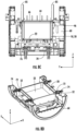
- FIGS. 3A and 3B are isometric views of an embodiment of a build box 18 which includes build plate 22 within powder bin 20.
- Powder bin 20 includes an open end 44 with upper clamp receivers 46 that extend from an end of powder bin 20 along the Y-axis.
- Powder bin 20 also has a pair of rails 48 with rollers 50 for transport within system 2. Rails 48 and rollers 50 extend along axis Y which is a direction of transport through the system 2.
- Y is a lateral transport direction and X is a transverse lateral direction.
- Four lateral clamp receivers 52 are at opposing ends (with respect to the Y-axis) of the powder bin 20 and face outwardly with respect to the X-axis.
- FIG. 4 is an isometric view of a portion of the build box 18 to put emphasis on latches 54 for securing the build plate 22 to the powder bin 20.
- the powder bin 20 includes four lower latches 54 that secure and provide a lower limit for the build plate 22 during the fabrication and cooling processes.
- the lower latches 54 individually have an upper surface 56 for engaging the build plate 22.
- the lower latches 54 individually are rotatively mounted about a hinge 58 having an axis of rotation parallel to the Y axis.
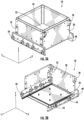
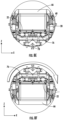
- FIG. 5 is an isometric view of a rotary frame 60 which is rotatively mounted within the bulk powder removal apparatus 8.
- Rotary frame 60 is configured to be rotated about a central axis 62 for up to a complete 360 degree rotation.
- the central axis 62 is parallel to Y and is at an approximate center of a circular cross-section of the rotary frame 60.
- Rotary frame 60 defines an internal receptacle cavity 64 for receiving the build box 18.
- the build box 18 is received into the internal receptacle cavity 64 along the Y axis.
- the orientation of the rotary frame 60 illustrated in FIG. 5 is a rotative "home" position for rotary frame 60.
- a rotation angle such as 90 degrees or 180 degrees refers to a clockwise rotation about central axis 62 from the home position.
- Rotary frame 60 includes an upper clamp 66 for engaging and clamping the open end 44 and upper clamp receivers 46 of the powder bin 20. Coupled between the upper clamp 66 and rotary frame 60 are actuators 68 for raising and lowering the upper clamp 66 along the vertical axis Z. Upper clamp 66 has an open top 70 to allow powder to exit at a rotation angles of about 180 degrees.
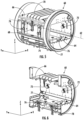
- FIG. 6 is a cutaway isometric view of the rotary frame 60.
- the axes X, Y, and Z have the same orientation for FIGS. 5 and 6 .
- Rotary frame 60 includes four lateral clamps 72 configured to extend and retract along the X-axis to engage and disengage the four lateral clamp receivers 52 of the powder bin 20. Coupled between the lateral clamps 72 and the rotary frame 60 are actuators 74 for extending and retracting the lateral clamp receivers 52 along the X-axis.
- Rotary frame 60 includes a clamping plate 76 configured to engage, clamp, and displace the build plate 22. Coupled between the clamping plate 76 and the rotary frame 60 is a lift apparatus 78 (see FIG. 8B , 8I for more views) for moving the clamping plate 76 into engagement with the build plate 22 and for extracting the build plate 22 from the powder bin 20.
- the clamping plate 76 includes one or more pneumatic chucks 77 for gripping portion(s) of the build plate 22.
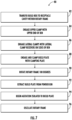
- FIG. 7 is a flowchart of an embodiment of a method 80 for removing bulk powder from the build box 18 using the bulk powder removal apparatus 8.
- Print engine 4 fabricated a 3D article 100 onto the upper surface 24 of build plate 22; unfused powder surrounds the 3D article above the upper surface and within the powder bin 20.
- the transport apparatus transported the build box 18 to the cooling station and time has elapsed for the contents of the build box 18 to cool.
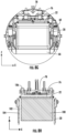
- FIG. 8A is a side cutaway YZ-view and FIG. 8B is a side cutaway XZ-view of the rotary frame 60 containing the build box 18 before any of the clamps (66, 72, 76) have engaged portions of the build box 18.
- clamps (66, 72, 76) are in their retracted state.
- FIG. 8C is a side cutaway through the YZ-plane illustrating step 84 (direction of motion indicated by block arrows 85).
- the upper clamp 66 then applies a vertical clamping force upon the build box 18.
- FIG. 8D is an isometric cutaway view illustrating step 86. After steps 84 and 86, the build box 18 is clamped and restrained vertically and laterally.
- FIG. 8E is a side cutaway view with a horizontal cut parallel to the X-plane illustrating step 88.
- the upward motion lifts the build plate 22 off of lower latches 54 and the build plate 22 is clamped with at least one pneumatic chuck 77 ( FIG. 6 ) that is part of the clamping plate 76.
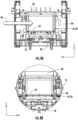
- FIG. 8F is a side cutaway XZ-view illustrating step 90. Because the powder bin 20 is open at the end opposite to the build plate 22, a majority of the unfused powder will then fall vertically downward and into a capturing portion of the bulk powder removal apparatus 8 below the rotary frame 60. Also, in the inverted 180 degree position of the rotary frame 60, the latches 54 rotate inwardly so that the build plate 22 can be extracted in step 92.
- FIG. 8G is a side cutaway XZ-view illustrating step 92 with lift apparatus 78 lifting the clamping plate 76 and extracting the build plate 22.
- FIG. 8H is a side schematic cutaway view illustrating isolated parts including the 3D article 100 with attached unfused powder coupled to the build plate 22 which is in turn coupled to the clamping plate 76.
- the 3D article 100 has been fabricated with a clearance 102 between inside surfaces 104 of the powder bin 20 and the 3D article 100.
- FIG. 8I is an isometric view of the powder bin 20, the build plate 22, and the clamping plate 76.
- FIGS. 8G, 8H , and 8I all correspond to step 92 in which the build plate 22 has been extracted from the powder bin 20 and therefore the build plate 22 is mechanically isolated from the powder bin 20.
- Wire rope isolators 106 also mechanically couple the clamping plate 76 to the rotary frame 60.
- the clamping plate 76 is vibration isolated from the powder bin 20 and from the rotary frame 60.
- Two agitation devices 108 are mounted to the clamping plate 76.
- the agitation devices 108 individually contain a motor coupled to an eccentric weight.
- the motor has an axis of rotation aligned with the X-axis.
- the primary vibratory force direction is along the vertical Z axis (perpendicular to the upper surface 24 of the build plate).
- a secondary vibratory force direction is along the Y-axis which is parallel to the upper surface 24.
- one or both of the agitation devices 108 are activated to facilitate and enhance removal of the unfused powder. Because the build plate clamp is vibration isolated from the powder bin 20 and the rotary frame 60, nearly all of the vibratory energy is transmitted and utilized for removing powder with minimal wasted energy that would otherwise vibrate the powder bin 20 and/or the rotary frame 60.
- FIG. 8J illustrates this rocking rotational motion about central axis 62 ( FIG. 5 ).
- This rocking motion further facilitates and enhances removal of the unfused powder.
- the rocking motion would be about the Y axis for plus and minus 90 degrees from the position of FIG. 8G (or between 90 and 270 degrees from the position of FIG. 8B ).
Description
- This non-provisional patent application claims priority to
U.S. Provisional Application Serial Number 63/065,859, Entitled "EFFICIENT BULK UNFUSED POWDER REMOVAL SYSTEM AND METHOD" by Ahren Hoy et al., filed on Aug 14, 2020 - The present invention concerns an apparatus and method for a layer-by-layer manufacture of three dimensional (3D) articles by selectively fusing or binding powder materials. More particularly, the present invention concerns a de-powdering system for efficiently removing unfused or unbound powder from build boxes that are generally too large and heavy for manual handling and lifting when filled with material.
- Three dimensional (3D) printing systems are in rapidly increasing use for purposes such as prototyping and manufacturing high value and/or customized articles. One type of three dimensional printer utilizes a layer-by-layer process to form a three dimensional article of manufacture from powdered materials. Each layer of powdered material is selectively fused using an energy beam such as a laser, electron, or particle beam or combined with a binder matrix. There is a desire to have large capacity systems that can fabricate physically large articles. One challenge with such systems is an efficient and safe method for a removal of unfused or unbound powder after fabrication is complete.
-
US 2016/279871 A discloses a device for unpacking a three-dimensional object, produced in an interchangeable container and/or on a construction platform by applying layers of a construction material in powder form and by selective hardening thereof, from the surrounding unhardened powder contains a rotating device for holding the interchangeable container and/or the construction platform, which rotating device is able to rotate the interchangeable container and/or the construction platform through an angle of at least 90° out of the upright position. -
EP 3167980 A discloses an unpacking device for use in an apparatus (10) for producing a three-dimensional work piece by irradiating layers of a raw material powder with electromagnetic or particle radiation, the unpacking device comprises a holding device which is configured to hold a building chamber arrangement. -
US 2018/215097 A provides an installation for cleaning a plate used in an additive manufacturing process performed using a powder. The installation includes an entry lock, an exit lock, a dry cleaner, a wet cleaner, and a conveyor system -
-
FIG. 1 is a schematic block diagram of an embodiment of an additive manufacturing system for producing a three-dimensional (3D) article. -
FIG. 2 is a schematic diagram of a 3D print engine. In the illustrated embodiment, the 3D print engine fabricates a 3D article through a layer by layer fusion melting of metal powder layers. -
FIG. 3A is an isometric view looking generally downward on an embodiment of a build box. For this figure and subsequent figures, mutually orthogonal axes X, Y, and Z will be used. The X and Y axes are generally lateral or horizontal. The Z axis is generally vertical and aligned with a gravitational reference. By "generally," it is assumed that a direction is by design but may vary within manufacturing tolerances. -
FIG. 3B is an isometric view looking generally upward on an embodiment of a build box. -
FIG. 4 is an isometric view of a portion of a build box which includes a powder bin and a build plate. Emphasis is on lower latches that secure the build plate within the powder bin. -
FIG. 5 is an isometric view of a rotary frame which is rotatively mounted within a bulk powder removal apparatus. -
FIG. 6 is a cutaway isometric view of a rotary frame with a vertical cut that is parallel to a YZ-plane. -
FIG. 7 is a flowchart of an embodiment of a method for removing bulk unfused powder from a build box. -
FIG. 8A is a side cutaway view of a rotary frame with a vertical cut parallel to a YZ-plane. The rotary frame defines an internal receptacle cavity within which a build box has been loaded. In an illustrated embodiment, the build box has been loaded in a direction parallel to a lateral Y-axis. -
FIG. 8B is a side cutaway view of a rotary frame with a vertical cut parallel to a XZ-plane. The rotary frame is in a "rotative home" or zero degree position in which an open top of the build box faces upwardly in the +Z direction. The rotative frame is configured to rotate on a central axis that is parallel to a lateral Y-axis. -
FIG. 8C is a side cutaway view of a rotary frame with a vertical cut parallel to a vertical YZ-plane. Compared toFIG. 8A , an upper clamp has been lowered and in vertical clamping engagement with a top of the build box. The upper clamp lowers along the Z-axis and provides clamping along the Z axis. -
FIG. 8D is an isometric cutaway view with a horizontal cut parallel to a lateral XY-plane. The rotary frame is in a rotative home position. Lateral clamps have been extended inwardly and in lateral clamping engagement with the build box. The lateral clamps move along the lateral X-axis and provide clamping along the lateral X-axis. -
FIG. 8E is a side cutaway view of a rotary frame with a vertical cut parallel to a XZ-plane. The rotary frame is in a rotative home position. Compared toFIG. 8B the build box has been vertically and laterally clamped and the clamping plate has been clamped to the build plate. The clamping plate is moved along the Z-axis to engagement with the build plate by a lift apparatus. -
FIG. 8F is a side cutaway view of a rotary frame with a vertical cut parallel to a XZ-plane. Compared toFIG. 8E , the rotary frame is rotated 180 degrees from the home position about a central axis parallel to the Y-axis. The central axis is defined as the axis of rotation of the rotary frame, and is generally at a center of the rotary frame relative to the XZ-plane. -
FIG. 8G is a side cutaway view of a rotary frame with a vertical cut parallel to a XZ-plane. Compared toFIG. 8F , the clamping plate has extracted the build plate from the powder bin in an upward (+Z) direction. The lift apparatus has operated to lift the clamping plate along the Z-axis to extract the build plate. -
FIG. 8H is a side schematic cutaway view illustrating a powder bin, a build plate, a build plate clamp, and a 3D article attached to the build plate. The orientation is 180 degrees from the home position so that an open side of the build box faces downward. The clamping plate is supporting the build plate in an extracted position relative to the powder bin. -
FIG. 8I is an isometric view of the powder bin, build plate, and build plate clamp. The build plate clamp is supporting the build plate in an extracted position relative to the powder bin. In the extracted position, the build plate is vibration isolated from the powder bin. In addition, features are shown at least partially vibration isolate the build plate from the rotary frame. -
FIG. 8J is a side cutaway view of a rotary frame with a vertical cut parallel to a XZ-plane. Compared toFIG. 8G , the rotary frame is rotatively oscillating between 90 and 270 degrees relative to the rotative home position. - In a first aspect, the invention provides an additive manufacturing system for producing a three-dimensional (3D) article according to claim 1.
- The disclosed system enables efficient and fully automated bulk removal of unfused powder from the 3D article. Operation of the clamps assures a very smooth rotation of the build box. Proper clamping is particularly important for a large metal powder build box due to an enormous weight of the 3D article and unfused powder. Having the agitation device mounted directly to the clamping plate maximizes a percentage of agitation energy that is transferred through the build plate to facilitate removal of powder with the least agitation energy.
- In one implementation, the print engine is configured to melt and fuse layers of the powder material using an energy beam. The energy beam can be a laser, an electron beam, or a particle beam.
- In another implementation, the transport mechanism transports the build box from the print engine to a cooling station. Step (1) includes transporting the build box from the cooling station to the internal receptacle cavity of the rotary frame.
- In yet another implementation, the plurality of clamps includes an upper clamp and at least one lateral clamp for clamping the build box along vertical and lateral axes during step (2). The lateral clamps can include lateral clamps that engage from opposing lateral directions. Providing clamping along multiple axes is advantageous when supporting and rotating a very heavy build box.
- In a further implementation, before step (4), the lift apparatus moves the clamp plate into clamping engagement with the build plate and then moves again to extract the build plate from the powder bin. This provides a vibration isolation between the build plate and the powder bin during operation of the agitation device. Wire ropes can provide vibration isolation between the build plate and the rotary frame. The vibration isolation reduces a requirement for a vibratory power level. The vibration isolation and reduced vibratory power level reduce NVH (noise, vibration, and harshness) which is advantageous for various reasons. This reduces vibratory damage to structural components of the manufacturing system including the build box, the rotary frame, and other components of the powder removal apparatus. This also reduces vibratory energy transfer to other components of the manufacturing system such as to the print engine. The powder deposition and beam system are both sensitive to vibrations.
- In a yet further implementation, during steps 1) and (2) the rotary frame is in a rotative home position of zero degrees at which an open top of the build box faces upward. During step (3) the rotary frame is rotated about 180 degrees from the home position about a central axis.
- In another implementation, the rotary frame rotates back and forth along a central axis to further facilitate unfused powder removal during step (4).
- In a second aspect, the invention provides a method of manufacturing a 3D article according to claim 9.
-
FIG. 1 is a schematic block diagram of an embodiment of an additive manufacturing (AM)system 2 for producing a three-dimensional (3D) article 100 (FIG. 8H ).System 2 includes a plurality of components at least including aprint engine 4, acooling station 6, a bulk powder removal apparatus orstation 8, a fine powder removal apparatus orstation 10, atransport apparatus 12, agas handling system 14, and acontroller 16. The various components 4-14 can individually have separate "lower level" controllers for controlling their internal functions. In some embodiments, a controller can function as a central controller. In the following description,controller 16 will be considered to include all controllers that may reside externally or within the components 4-14.Controller 16 can be internal toAM system 2, external toAM system 2, or include portions that are both internal and external toAM system 2. - The
transport apparatus 12 is for transporting abuild box 18 through the various components 4-10 in a sequence that includes fabricating, cooling, and de-powdering a 3D article being manufactured. Thegas handling system 14 is for controlling an environment for components 4-10. In one embodiment, the gas handling system is configured to evacuate components 4-10 and then to backfill them with a non-oxidizing gas such as argon or nitrogen in order to maintain thebuild box 18 within a non-oxidizing environment. -
Controller 16 includes a processor coupled to a non-transient or nonvolatile information storage device which stores software instructions. When executed by the processor, the software instructions operate any or all portions of thesystem 2. In an illustrative embodiment, fabrication, cooling, de-powdering, and other functions can be performed in a fully automated way bycontroller 16. -
Controller 16 is configured to perform steps such as (1) operategas handling system 14 to evacuate and backfill components 4-10, (2) operateprint engine 4 to fabricate a3D article 100 inbuild box 18, (3) operatetransport apparatus 12 to transport build box 18 (which now contains the 3D article and unfused powder) to thecooling station 6, (4) after an appropriate cooling time, operate transport apparatus to transportbuild box 18 to buildpowder removal station 8, (5) operate bulkpowder removal apparatus 8 to remove most of the unfused powder from thebuild box 18, and (6) operatetransport apparatus 12 to transport thebuild box 18 to the finepowder removal station 10. At the finepowder removal station 10, residual unfused powder is removed either automatically or manually. All the while,controller 16 operates thegas handling system 14 to maintain the non-oxidizing gaseous environment within the components 4-10 as required. -
AM system 2 can have other components such as an inspection station or a station for facilitating unloading of the3D article 100 from thebuild box 18. The additional components can be manually operated or under control ofcontroller 16. -
FIG. 2 is a schematic diagram of an embodiment of a3D print engine 4. In describingFIG. 2 and for subsequent figures, mutually orthogonal axes X, Y and Z can be used. Axes X and Y are lateral axes that are generally horizontal. Axis Z is a vertical axis that is generally aligned with a gravitational reference. By "generally" it is intended to be so by design but may vary due to manufacturing or other tolerances. - The
build box 18 includes apowder bin 20 containing abuild plate 22. Buildplate 22 has anupper surface 24 and is mechanically coupled to avertical positioning system 26. Thebuild box 18 is configured to contain dispensed metal powder (not shown). Thebuild box 18 is contained withinchamber 28 surrounded byhousing 30. - A
metal powder dispenser 32 is configured to dispense layers of metal powder upon theupper surface 24 of thebuild plate 22 or on previously dispensed layers of metal. In the illustrated embodiment, asecond powder dispenser 34 is configured to dispense an additional powder such as another metal or a support material.Powder dispensers -
Print engine 4 includes abeam system 40 configured to generate abeam 42 for selectively fusing layers of dispensed metal powder. In an illustrative embodiment, thebeam system 40 includes a plurality of high power lasers for generating radiation beams individually having an optical power layer of at least 100 watts, at least 500 watts, or about 1000 watts or more. Thebeam system 40 can include optics for individually steering the radiation beams across a build plane that is coincident with an upper surface of a layer of metal powder. In alternative embodiments, thebeam system 40 can generate electron beams, particle beams, or a hybrid mixture of different beam types. - The
controller 16 can be configured to operate theprint engine 4 to fabricate a 3D article: (1) operate thevertical positioning system 26 to position anupper surface 24 ofbuild plate 26 or of a previously deposited layer of powder at one powder layer thickness below a build plane, (2) operatedispenser 32 to dispense a layer of metal powder on theupper surface 24, (3) operate the beam system to selectively fuse the just-dispensed layer of metal powder, and then repeat steps 1-3 to finish fabrication of the 3D article. The controller can also operatepowder dispenser 34 and other components ofprint engine 4 as part of the fabrication. -
FIGS. 3A and 3B are isometric views of an embodiment of abuild box 18 which includesbuild plate 22 withinpowder bin 20.Powder bin 20 includes anopen end 44 withupper clamp receivers 46 that extend from an end ofpowder bin 20 along the Y-axis.Powder bin 20 also has a pair ofrails 48 withrollers 50 for transport withinsystem 2.Rails 48 androllers 50 extend along axis Y which is a direction of transport through thesystem 2. Y is a lateral transport direction and X is a transverse lateral direction. Fourlateral clamp receivers 52 are at opposing ends (with respect to the Y-axis) of thepowder bin 20 and face outwardly with respect to the X-axis. -
FIG. 4 is an isometric view of a portion of thebuild box 18 to put emphasis onlatches 54 for securing thebuild plate 22 to thepowder bin 20. Thepowder bin 20 includes fourlower latches 54 that secure and provide a lower limit for thebuild plate 22 during the fabrication and cooling processes. The lower latches 54 individually have anupper surface 56 for engaging thebuild plate 22. The lower latches 54 individually are rotatively mounted about ahinge 58 having an axis of rotation parallel to the Y axis. -
FIG. 5 is an isometric view of arotary frame 60 which is rotatively mounted within the bulkpowder removal apparatus 8.Rotary frame 60 is configured to be rotated about acentral axis 62 for up to a complete 360 degree rotation. Thecentral axis 62 is parallel to Y and is at an approximate center of a circular cross-section of therotary frame 60.Rotary frame 60 defines aninternal receptacle cavity 64 for receiving thebuild box 18. Thebuild box 18 is received into theinternal receptacle cavity 64 along the Y axis. The orientation of therotary frame 60 illustrated inFIG. 5 is a rotative "home" position forrotary frame 60. A rotation angle such as 90 degrees or 180 degrees refers to a clockwise rotation aboutcentral axis 62 from the home position. -
Rotary frame 60 includes anupper clamp 66 for engaging and clamping theopen end 44 andupper clamp receivers 46 of thepowder bin 20. Coupled between theupper clamp 66 androtary frame 60 areactuators 68 for raising and lowering theupper clamp 66 along the vertical axis Z.Upper clamp 66 has an open top 70 to allow powder to exit at a rotation angles of about 180 degrees. -
FIG. 6 is a cutaway isometric view of therotary frame 60. The axes X, Y, and Z have the same orientation forFIGS. 5 and 6 .Rotary frame 60 includes fourlateral clamps 72 configured to extend and retract along the X-axis to engage and disengage the fourlateral clamp receivers 52 of thepowder bin 20. Coupled between the lateral clamps 72 and therotary frame 60 areactuators 74 for extending and retracting thelateral clamp receivers 52 along the X-axis. -
Rotary frame 60 includes a clampingplate 76 configured to engage, clamp, and displace thebuild plate 22. Coupled between the clampingplate 76 and therotary frame 60 is a lift apparatus 78 (seeFIG. 8B ,8I for more views) for moving the clampingplate 76 into engagement with thebuild plate 22 and for extracting thebuild plate 22 from thepowder bin 20. The clampingplate 76 includes one or morepneumatic chucks 77 for gripping portion(s) of thebuild plate 22. -
FIG. 7 is a flowchart of an embodiment of amethod 80 for removing bulk powder from thebuild box 18 using the bulkpowder removal apparatus 8. Prior to method 80: (1)Print engine 4 fabricated a3D article 100 onto theupper surface 24 ofbuild plate 22; unfused powder surrounds the 3D article above the upper surface and within thepowder bin 20. (2) The transport apparatus transported thebuild box 18 to the cooling station and time has elapsed for the contents of thebuild box 18 to cool. - According to 82, the
transport apparatus 12 transfers thebuild box 18 to theinternal receptacle cavity 64 of the rotary frame 60 (direction of motion indicated byblock arrow 83 along Y-axis).FIG. 8A is a side cutaway YZ-view andFIG. 8B is a side cutaway XZ-view of therotary frame 60 containing thebuild box 18 before any of the clamps (66, 72, 76) have engaged portions of thebuild box 18. Thus, clamps (66, 72, 76) are in their retracted state. - According to 84, the actuator(s) 68 are retracted to lower and engage the
upper clamp 66 with theopen end 44 andupper clamp receivers 46 of thepowder bin 20.FIG. 8C is a side cutaway through the YZ-plane illustrating step 84 (direction of motion indicated by block arrows 85). Theupper clamp 66 then applies a vertical clamping force upon thebuild box 18. - According to 86, the
actuators 74 are expanded inwardly along the X-axis to engage the lateral clamps 72 with thelateral clamp receivers 52.FIG. 8D is an isometric cutawayview illustrating step 86. Aftersteps build box 18 is clamped and restrained vertically and laterally. - According to 88, the
lift apparatus 78 raises the clampingplate 76 which engages and clamps thebuild plate 22.FIG. 8E is a side cutaway view with a horizontal cut parallel to theX-plane illustrating step 88. The upward motion lifts thebuild plate 22 off oflower latches 54 and thebuild plate 22 is clamped with at least one pneumatic chuck 77 (FIG. 6 ) that is part of the clampingplate 76. - According to 90, the
rotary frame 60 is rotated 180 degrees while thepowder bin 20 and buildplate 22 are separately clamped to therotary frame 60.FIG. 8F is a side cutaway XZ-view illustrating step 90. Because thepowder bin 20 is open at the end opposite to thebuild plate 22, a majority of the unfused powder will then fall vertically downward and into a capturing portion of the bulkpowder removal apparatus 8 below therotary frame 60. Also, in the inverted 180 degree position of therotary frame 60, thelatches 54 rotate inwardly so that thebuild plate 22 can be extracted instep 92. - According to 92, the lift apparatus raises the clamping
plate 76 to extract thebuild plate 22 from thepowder bin 20. This is an important step to provide vibration isolation of thebuild plate 22 from thepowder bin 20.FIG. 8G is a side cutaway XZ-view illustrating step 92 withlift apparatus 78 lifting the clampingplate 76 and extracting thebuild plate 22. -
FIG. 8H is a side schematic cutaway view illustrating isolated parts including the3D article 100 with attached unfused powder coupled to thebuild plate 22 which is in turn coupled to the clampingplate 76. The3D article 100 has been fabricated with aclearance 102 betweeninside surfaces 104 of thepowder bin 20 and the3D article 100. -
FIG. 8I is an isometric view of thepowder bin 20, thebuild plate 22, and the clampingplate 76.FIGS. 8G, 8H , and8I all correspond to step 92 in which thebuild plate 22 has been extracted from thepowder bin 20 and therefore thebuild plate 22 is mechanically isolated from thepowder bin 20.Wire rope isolators 106 also mechanically couple the clampingplate 76 to therotary frame 60. Thus, the clampingplate 76 is vibration isolated from thepowder bin 20 and from therotary frame 60. Thewire rope isolators 106 have a higher stiffness Kc along the X-axis and a lower stiffness Ka = 0.5 Kc along the Y-axis and a lower stiffness Kb = 0.5Kc along the Z-axis. - Two
agitation devices 108 are mounted to the clampingplate 76. In the illustrated embodiment, theagitation devices 108 individually contain a motor coupled to an eccentric weight. The motor has an axis of rotation aligned with the X-axis. The primary vibratory force direction is along the vertical Z axis (perpendicular to theupper surface 24 of the build plate). A secondary vibratory force direction is along the Y-axis which is parallel to theupper surface 24. - According to 94, one or both of the
agitation devices 108 are activated to facilitate and enhance removal of the unfused powder. Because the build plate clamp is vibration isolated from thepowder bin 20 and therotary frame 60, nearly all of the vibratory energy is transmitted and utilized for removing powder with minimal wasted energy that would otherwise vibrate thepowder bin 20 and/or therotary frame 60. - According to 96, concurrent with operating the agitation device(s) 108, the rotary frame rotates back and forth from the position of
FIG. 8G .FIG. 8J illustrates this rocking rotational motion about central axis 62 (FIG. 5 ). This rocking motion further facilitates and enhances removal of the unfused powder. In an illustrative embodiment, the rocking motion would be about the Y axis for plus and minus 90 degrees from the position ofFIG. 8G (or between 90 and 270 degrees from the position ofFIG. 8B ). - The specific embodiments and applications thereof described above are for illustrative purposes only and do not preclude modifications and variations encompassed by the scope of the following claims.
Claims (15)
- An additive manufacturing system for producing a three-dimensional (3D) article comprising:a print engine (4) configured to produce the article in a layer-by-layer manner by the fusion or binding of powder material;a build box (18) including a powder bin (20) and a build plate (22);a post-fabrication powder removal apparatus including:a rotary frame (60) defining an internal receptacle cavity (64);a plurality of clamps (66, 72) coupled to a corresponding plurality of actuators (68, 74); anda clamping plate (76) coupled to a lift apparatus (78);an agitation device (108) mounted to the clamping plate (76);a transport mechanism; anda controller (16) configured to perform the following steps:(1) operate the transport mechanism to transport the build box (18) to the internal receptacle cavity; cavity (64);(2) operate the plurality of actuators to engage the build box (18) with the plurality of clamps to secure the build box to the rotary frame (60);(3) operate the rotary frame to rotate the build box (18) until unfused powder begins to exit the build box (18); and(4) operate the agitation device (108) to facilitate pouring of the unfused powder from the build box (18).
- The additive manufacturing system of claim 1 wherein the print engine (4) is configured to melt and fuse layers of the powder material with the action of an energy beam.
- The additive manufacturing system of claim 1 wherein, before step (1), the transport mechanism transports the build box (18) from the print engine (4) to a cooling station (6) and step (1) includes a transport of the build box (18) from the cooling station (6) to the internal receptacle cavity (64).
- The additive manufacturing system of claim 1 wherein the plurality of clamps (66, 72) includes an upper clamp (66) for vertically clamping the build box (18) in step (2), or wherein the plurality of clamps (66,72) includes a plurality of lateral clamps (72) for horizontally clamping the build box (18) during step (2) or wherein the plurality of clamps (66, 72) includes an upper clamp (66) and at least one lateral clamp (72) for clamping the build box (18) along vertical and lateral axes during step (2).
- The additive manufacturing system of claim 1 wherein the lift apparatus (78) raises the clamping plate (76) to engage the clamp plate (76) to the build plate (22), wherein the powder bin (20) includes at least one latch (54) for securing the build plate (22) to the powder bin (20), operation of the lift apparatus (78) disengages the at least one latch (54) or wherein before step (4), the lift apparatus (78) moves to extract the build plate (22) from the powder bin (20).
- The additive manufacturing system of claim 1 wherein during steps (1) and (2) the rotary frame (60) is in a rotative home position of zero degrees at which an open top of the build box (18) faces upward, during step (3) the rotary frame is rotated about 180 degrees from the home position about a central axis.
- The additive manufacturing system of claim 1 wherein the agitation is primarily exerted along a vertical axis.
- The additive manufacturing system of claim 1 wherein during step (4), the rotary frame (60) rotates back and forth along a central axis parallel to a Y-axis to further facilitate unfused powder removal.
- A method of manufacturing a 3D article comprising:
providing:a print engine (4) configured to produce the article in a layer-by-layer manner by the fusion or binding of powder material;a build box (18) including a powder bin (20) and a build plate (22);a post fabrication powder removal apparatus including:a rotary frame (60) defining an internal receptacle cavity (64)a plurality of clamps (66, 72) coupled to a corresponding plurality of actuators (68, 74); anda clamping plate (76) coupled to a lift apparatus (78);an agitation device (108) mounted to the clamping plate (76);a transport mechanism; and(1) operating the transport mechanism to transport the build box (18) to the internal receptacle cavity (64);(2) operating the plurality of actuators (68, 74) to engage the build box (18) with the plurality of clamps (66, 72) to secure the build box (18) to the rotary frame (60);(3) operating the rotary frame (60) to rotate the build box (18) until unfused powder begins to exit the build box (18); and(4) operating the agitation device (108) to facilitate pouring of the unfused powder from the build box (18). - The method of claim 9 wherein the plurality of clamps (66, 72) includes an upper clamp (66) for vertically clamping the build box (18) in step (2).
- The method of claim 9 wherein the plurality of clamps (66, 72) includes a plurality of lateral clamps (72) for horizontally clamping the build box during step (2)
- The method of claim 9 after step (2) but before step (3) the lift apparatus (78) raises the clamping plate (76) to engage the clamp build plate (22) to the clamping plate (76).
- The method of claim 12 wherein before step (4), the lift apparatus (78) moves to extract the build plate (22) from the powder bin. (20).
- The method of claim 12 wherein before step (4), the lift apparatus (78) moves the clamp plate (76) into clamping engagement with the build plate (22) and then moves again to extract the build plate (22) from the powder bin (20).
- An additive manufacturing system for producing a three-dimensional (3D) article according to claim 1, wherein:the post fabrication power removal apparatus including:a rotary frame (60) defining an internal receptacle cavity (64);a plurality of clamps (66, 72) including an upper clamp (66) and at least one lateral clamp (72), theplurality of clamps (66, 72) individually coupled to an actuator (68, 74);a clamping plate (76) coupled to a lift apparatus (78); andand an agitation device (108) mounted to the clamping plate (76); and whereinthe controller (16) is configured to perform the following steps:(1) operate the transport mechanism to transport the build box (18) to the internal receptacle cavity (64);(2) operate the plurality of clamps (66, 72) to secure the build box to the rotary frame (60);(3) operate lift apparatus (78) to engage and clamp the clamping plate (76) to the build plate (22);(4) operate the rotary frame (60) to rotate the build box (18) to allow unfused powder to exit the build box (18);(5) operate the lift apparatus (78) to extract the build plate (76) from the powder bin (20);(6) operate the agitation device (108) to agitate the build plate (22) to facilitate pouring of the unfused powder from the build box (18); and(7) concurrent with operating the build plate handling device agitate the build plate (76) operate the rotary frame (60) to oscillate the build box (18) back and forth to further facilitate removal of unfused powder.
Applications Claiming Priority (2)
| Application Number | Priority Date | Filing Date | Title |
|---|---|---|---|
| US202063065859P | 2020-08-14 | 2020-08-14 | |
| PCT/US2021/046081 WO2022036304A2 (en) | 2020-08-14 | 2021-08-16 | Efficient bulk unfused powder removal system and method |
Publications (2)
| Publication Number | Publication Date |
|---|---|
| EP4196303A2 EP4196303A2 (en) | 2023-06-21 |
| EP4196303B1 true EP4196303B1 (en) | 2024-03-13 |
Family
ID=79287636
Family Applications (1)
| Application Number | Title | Priority Date | Filing Date |
|---|---|---|---|
| EP21840209.7A Active EP4196303B1 (en) | 2020-08-14 | 2021-08-16 | Efficient bulk unfused powder removal system and method |
Country Status (4)
| Country | Link |
|---|---|
| US (2) | US11597016B2 (en) |
| EP (1) | EP4196303B1 (en) |
| JP (1) | JP2023537920A (en) |
| WO (1) | WO2022036304A2 (en) |
Citations (1)
| Publication number | Priority date | Publication date | Assignee | Title |
|---|---|---|---|---|
| EP3486007A1 (en) * | 2017-11-15 | 2019-05-22 | National Chung-Shan Institute of Science and Technology | Additive manufacturing chamber, additive manufacturing module and additive manufacturing apparatus therewith |
Family Cites Families (8)
| Publication number | Priority date | Publication date | Assignee | Title |
|---|---|---|---|---|
| US8601907B2 (en) * | 2004-09-24 | 2013-12-10 | Kai U.S.A., Ltd. | Knife blade manufacturing process |
| JP6197036B2 (en) * | 2012-07-19 | 2017-09-13 | アダミス ファーマシューティカルズ コーポレーション | Powder feeder |
| DE102013223407A1 (en) * | 2013-11-15 | 2015-05-21 | Eos Gmbh Electro Optical Systems | Apparatus and method for layering a three-dimensional object and unpacking the finished object |
| US10011892B2 (en) * | 2014-08-21 | 2018-07-03 | Honeywell International Inc. | Methods for producing alloy forms from alloys containing one or more extremely reactive elements and for fabricating a component therefrom |
| US9855704B2 (en) * | 2015-02-27 | 2018-01-02 | Technology Research Association For Future Additive Manufacturing | Powder recoater |
| FR3039438B1 (en) * | 2015-07-30 | 2017-08-18 | Michelin & Cie | INSTALLATION FOR CLEANING ADDITIVE MANUFACTURING TRAYS |
| EP3167980A1 (en) * | 2015-11-13 | 2017-05-17 | SLM Solutions Group AG | Unpacking device allowing residual raw material powder removal |
| US11484944B2 (en) * | 2019-02-11 | 2022-11-01 | 3D Systems, Inc. | Three-dimensional printer with two state filter for powdered metal |
-
2021
- 2021-08-16 JP JP2023508550A patent/JP2023537920A/en active Pending
- 2021-08-16 EP EP21840209.7A patent/EP4196303B1/en active Active
- 2021-08-16 US US17/402,811 patent/US11597016B2/en active Active
- 2021-08-16 WO PCT/US2021/046081 patent/WO2022036304A2/en unknown
-
2023
- 2023-02-03 US US18/163,956 patent/US11794254B1/en active Active
Patent Citations (1)
| Publication number | Priority date | Publication date | Assignee | Title |
|---|---|---|---|---|
| EP3486007A1 (en) * | 2017-11-15 | 2019-05-22 | National Chung-Shan Institute of Science and Technology | Additive manufacturing chamber, additive manufacturing module and additive manufacturing apparatus therewith |
Also Published As
| Publication number | Publication date |
|---|---|
| WO2022036304A3 (en) | 2022-03-24 |
| US11597016B2 (en) | 2023-03-07 |
| WO2022036304A2 (en) | 2022-02-17 |
| US20220111443A1 (en) | 2022-04-14 |
| JP2023537920A (en) | 2023-09-06 |
| US11794254B1 (en) | 2023-10-24 |
| US20230364681A1 (en) | 2023-11-16 |
| EP4196303A2 (en) | 2023-06-21 |
Similar Documents
| Publication | Publication Date | Title |
|---|---|---|
| JP6667521B2 (en) | Production equipment for producing multiple parts simultaneously and productively | |
| JP3790473B2 (en) | Apparatus and method for formally manufacturing three-dimensional objects | |
| CN108290180B (en) | Additive manufacturing system and method | |
| US20210379828A1 (en) | Powder bed fusion apparatus and methods | |
| KR101463473B1 (en) | Transfer device | |
| KR20050044434A (en) | Reduced footprlnt tool for automated processing of microelectronic substrates | |
| KR20220060513A (en) | Improved substrate storage and processing | |
| CN1895971A (en) | System for transferring flat panel display substrates during manufacture | |
| US20070157878A1 (en) | Production system for wafer | |
| EP4196303B1 (en) | Efficient bulk unfused powder removal system and method | |
| US20200156150A1 (en) | Object shaping system | |
| CN209189744U (en) | A kind of adaptive robot handgrip that sand core is carried | |
| EP3374109A1 (en) | Device for storage of modular functional units | |
| EP3456518A1 (en) | Apparatus for additively manufacturing three-dimensional objects | |
| US20190091765A1 (en) | High capacity apparatus for layered manufacturing from powdered materials | |
| CN111655459A (en) | Method for taking out 3D printing part | |
| EP3686009B1 (en) | Powder module for an apparatus for additively manufacturing three-dimensional objects | |
| US20160133456A1 (en) | Apparatus and method for treating a substrate | |
| WO2023217496A1 (en) | Additive manufacturing facility | |
| CN212794935U (en) | Defeated material stop device based on automatic processing of industrial robot | |
| TW201921573A (en) | Method and device for transporting substrates | |
| JPH0441305A (en) | Pallet containing shelf apparatus | |
| JPH11246036A (en) | Conveying device and delivery device | |
| JPH0422532A (en) | Manufacture of pattern |
Legal Events
| Date | Code | Title | Description |
|---|---|---|---|
| STAA | Information on the status of an ep patent application or granted ep patent |
Free format text: STATUS: UNKNOWN |
|
| STAA | Information on the status of an ep patent application or granted ep patent |
Free format text: STATUS: THE INTERNATIONAL PUBLICATION HAS BEEN MADE |
|
| PUAI | Public reference made under article 153(3) epc to a published international application that has entered the european phase |
Free format text: ORIGINAL CODE: 0009012 |
|
| STAA | Information on the status of an ep patent application or granted ep patent |
Free format text: STATUS: REQUEST FOR EXAMINATION WAS MADE |
|
| 17P | Request for examination filed |
Effective date: 20230117 |
|
| AK | Designated contracting states |
Kind code of ref document: A2 Designated state(s): AL AT BE BG CH CY CZ DE DK EE ES FI FR GB GR HR HU IE IS IT LI LT LU LV MC MK MT NL NO PL PT RO RS SE SI SK SM TR |
|
| GRAJ | Information related to disapproval of communication of intention to grant by the applicant or resumption of examination proceedings by the epo deleted |
Free format text: ORIGINAL CODE: EPIDOSDIGR1 |
|
| STAA | Information on the status of an ep patent application or granted ep patent |
Free format text: STATUS: GRANT OF PATENT IS INTENDED |
|
| DAV | Request for validation of the european patent (deleted) | ||
| DAX | Request for extension of the european patent (deleted) | ||
| GRAP | Despatch of communication of intention to grant a patent |
Free format text: ORIGINAL CODE: EPIDOSNIGR1 |
|
| RIC1 | Information provided on ipc code assigned before grant |
Ipc: B08B 7/02 20060101ALI20231103BHEP Ipc: B33Y 40/20 20200101ALI20231103BHEP Ipc: B22F 12/86 20210101ALI20231103BHEP Ipc: B22F 12/00 20210101ALI20231103BHEP Ipc: B08B 1/00 20060101ALI20231103BHEP Ipc: B22F 10/68 20210101AFI20231103BHEP |
|
| INTG | Intention to grant announced |
Effective date: 20231123 |
|
| P01 | Opt-out of the competence of the unified patent court (upc) registered |
Effective date: 20231130 |
|
| GRAS | Grant fee paid |
Free format text: ORIGINAL CODE: EPIDOSNIGR3 |
|
| GRAA | (expected) grant |
Free format text: ORIGINAL CODE: 0009210 |
|
| STAA | Information on the status of an ep patent application or granted ep patent |
Free format text: STATUS: THE PATENT HAS BEEN GRANTED |
|
| AK | Designated contracting states |
Kind code of ref document: B1 Designated state(s): AL AT BE BG CH CY CZ DE DK EE ES FI FR GB GR HR HU IE IS IT LI LT LU LV MC MK MT NL NO PL PT RO RS SE SI SK SM TR |
|
| REG | Reference to a national code |
Ref country code: GB Ref legal event code: FG4D |
|
| REG | Reference to a national code |
Ref country code: CH Ref legal event code: EP |
|
| REG | Reference to a national code |
Ref country code: DE Ref legal event code: R096 Ref document number: 602021010505 Country of ref document: DE |