EP3485225B1 - Berührungsfreie sensorik - Google Patents
Berührungsfreie sensorik Download PDFInfo
- Publication number
- EP3485225B1 EP3485225B1 EP17733051.1A EP17733051A EP3485225B1 EP 3485225 B1 EP3485225 B1 EP 3485225B1 EP 17733051 A EP17733051 A EP 17733051A EP 3485225 B1 EP3485225 B1 EP 3485225B1
- Authority
- EP
- European Patent Office
- Prior art keywords
- coil
- coils
- voltage
- target structure
- sensor
- Prior art date
- Legal status (The legal status is an assumption and is not a legal conclusion. Google has not performed a legal analysis and makes no representation as to the accuracy of the status listed.)
- Active
Links
Images


Classifications
-
- G—PHYSICS
- G01—MEASURING; TESTING
- G01V—GEOPHYSICS; GRAVITATIONAL MEASUREMENTS; DETECTING MASSES OR OBJECTS; TAGS
- G01V3/00—Electric or magnetic prospecting or detecting; Measuring magnetic field characteristics of the earth, e.g. declination, deviation
- G01V3/02—Electric or magnetic prospecting or detecting; Measuring magnetic field characteristics of the earth, e.g. declination, deviation operating with propagation of electric current
-
- G—PHYSICS
- G01—MEASURING; TESTING
- G01B—MEASURING LENGTH, THICKNESS OR SIMILAR LINEAR DIMENSIONS; MEASURING ANGLES; MEASURING AREAS; MEASURING IRREGULARITIES OF SURFACES OR CONTOURS
- G01B7/00—Measuring arrangements characterised by the use of electric or magnetic techniques
- G01B7/02—Measuring arrangements characterised by the use of electric or magnetic techniques for measuring length, width or thickness
- G01B7/023—Measuring arrangements characterised by the use of electric or magnetic techniques for measuring length, width or thickness for measuring distance between sensor and object
-
- G—PHYSICS
- G01—MEASURING; TESTING
- G01D—MEASURING NOT SPECIALLY ADAPTED FOR A SPECIFIC VARIABLE; ARRANGEMENTS FOR MEASURING TWO OR MORE VARIABLES NOT COVERED IN A SINGLE OTHER SUBCLASS; TARIFF METERING APPARATUS; MEASURING OR TESTING NOT OTHERWISE PROVIDED FOR
- G01D5/00—Mechanical means for transferring the output of a sensing member; Means for converting the output of a sensing member to another variable where the form or nature of the sensing member does not constrain the means for converting; Transducers not specially adapted for a specific variable
- G01D5/12—Mechanical means for transferring the output of a sensing member; Means for converting the output of a sensing member to another variable where the form or nature of the sensing member does not constrain the means for converting; Transducers not specially adapted for a specific variable using electric or magnetic means
- G01D5/14—Mechanical means for transferring the output of a sensing member; Means for converting the output of a sensing member to another variable where the form or nature of the sensing member does not constrain the means for converting; Transducers not specially adapted for a specific variable using electric or magnetic means influencing the magnitude of a current or voltage
- G01D5/20—Mechanical means for transferring the output of a sensing member; Means for converting the output of a sensing member to another variable where the form or nature of the sensing member does not constrain the means for converting; Transducers not specially adapted for a specific variable using electric or magnetic means influencing the magnitude of a current or voltage by varying inductance, e.g. by a movable armature
- G01D5/2006—Mechanical means for transferring the output of a sensing member; Means for converting the output of a sensing member to another variable where the form or nature of the sensing member does not constrain the means for converting; Transducers not specially adapted for a specific variable using electric or magnetic means influencing the magnitude of a current or voltage by varying inductance, e.g. by a movable armature by influencing the self-induction of one or more coils
- G01D5/202—Mechanical means for transferring the output of a sensing member; Means for converting the output of a sensing member to another variable where the form or nature of the sensing member does not constrain the means for converting; Transducers not specially adapted for a specific variable using electric or magnetic means influencing the magnitude of a current or voltage by varying inductance, e.g. by a movable armature by influencing the self-induction of one or more coils by movable a non-ferromagnetic conductive element
- G01D5/2026—Mechanical means for transferring the output of a sensing member; Means for converting the output of a sensing member to another variable where the form or nature of the sensing member does not constrain the means for converting; Transducers not specially adapted for a specific variable using electric or magnetic means influencing the magnitude of a current or voltage by varying inductance, e.g. by a movable armature by influencing the self-induction of one or more coils by movable a non-ferromagnetic conductive element constituting a short-circuiting element
-
- G—PHYSICS
- G01—MEASURING; TESTING
- G01D—MEASURING NOT SPECIALLY ADAPTED FOR A SPECIFIC VARIABLE; ARRANGEMENTS FOR MEASURING TWO OR MORE VARIABLES NOT COVERED IN A SINGLE OTHER SUBCLASS; TARIFF METERING APPARATUS; MEASURING OR TESTING NOT OTHERWISE PROVIDED FOR
- G01D5/00—Mechanical means for transferring the output of a sensing member; Means for converting the output of a sensing member to another variable where the form or nature of the sensing member does not constrain the means for converting; Transducers not specially adapted for a specific variable
- G01D5/12—Mechanical means for transferring the output of a sensing member; Means for converting the output of a sensing member to another variable where the form or nature of the sensing member does not constrain the means for converting; Transducers not specially adapted for a specific variable using electric or magnetic means
- G01D5/14—Mechanical means for transferring the output of a sensing member; Means for converting the output of a sensing member to another variable where the form or nature of the sensing member does not constrain the means for converting; Transducers not specially adapted for a specific variable using electric or magnetic means influencing the magnitude of a current or voltage
- G01D5/20—Mechanical means for transferring the output of a sensing member; Means for converting the output of a sensing member to another variable where the form or nature of the sensing member does not constrain the means for converting; Transducers not specially adapted for a specific variable using electric or magnetic means influencing the magnitude of a current or voltage by varying inductance, e.g. by a movable armature
- G01D5/204—Mechanical means for transferring the output of a sensing member; Means for converting the output of a sensing member to another variable where the form or nature of the sensing member does not constrain the means for converting; Transducers not specially adapted for a specific variable using electric or magnetic means influencing the magnitude of a current or voltage by varying inductance, e.g. by a movable armature by influencing the mutual induction between two or more coils
- G01D5/2053—Mechanical means for transferring the output of a sensing member; Means for converting the output of a sensing member to another variable where the form or nature of the sensing member does not constrain the means for converting; Transducers not specially adapted for a specific variable using electric or magnetic means influencing the magnitude of a current or voltage by varying inductance, e.g. by a movable armature by influencing the mutual induction between two or more coils by a movable non-ferromagnetic conductive element
-
- H—ELECTRICITY
- H03—ELECTRONIC CIRCUITRY
- H03K—PULSE TECHNIQUE
- H03K17/00—Electronic switching or gating, i.e. not by contact-making and –breaking
- H03K17/94—Electronic switching or gating, i.e. not by contact-making and –breaking characterised by the way in which the control signals are generated
- H03K17/945—Proximity switches
- H03K17/95—Proximity switches using a magnetic detector
- H03K17/952—Proximity switches using a magnetic detector using inductive coils
- H03K2017/9527—Details of coils in the emitter or receiver; Magnetic detector comprising emitting and receiving coils
Definitions
- the present disclosure relates to a position sensor, and more particularly to a contactless sensor for determining a presence and/or relative position of a target structure in a proximity to the sensor.
- Position sensors such as brushes, slip rings, or wire conductors, often employ contacts to indicate the position of a movable member.
- the elimination of contacts is desirable and can reduce electrical noise and disturbances caused by sliding electric contact.
- the contactless sensors maintain a gap between the sensor and a target structure, which can be challenging to maintain the sensing range in the presence of such a physical gap.
- Examples of contactless sensors include capacitance-based position sensors, laser-based position sensors, eddy-current sensing position sensors, and linear displacement transducer-based position sensors. While each type of position sensor has its advantages, each type of the sensor may be best suited for a particular application. For example, the size of capacitors can make the sensor impractical when the position sensor must be small in size. The optical sensor can fail in the presence of dirt or grease. Magnetic sensors require precision housings and mechanical assembly to avoid errors caused by magnet or sensor misalignment, which can be difficult in some applications. In addition, in some applications, the size of the gap between the sensor and the target structure can change with time, and the location of the target structure can cause problems to the accuracy of some linear position sensors.
- US 2013/0328516 A1 discloses that a method for detecting a position of a movable element of a drive apparatus by means of a position detection apparatus comprising at least one field coil and at least one secondary coil associated with the field coil, wherein an electrical excitation pulse is applied to the field coil in order to induce an electrical voltage in the secondary coil, a secondary coil voltage is measured and the position of the movable element is determined on the basis of the measured secondary coil voltage.
- DE 4311973 A1 discloses that the transmitter coils are fed with two alternating voltages so that the stray alternating fields induce a voltage within the secondary coil.
- Cunyue LIU ET AL "Response Coupling of a Passive Inductance-Capacitance-Resistor Loop in Coil-Based Sensing System", IEEE SENSORS JOURNAL, IEEE SERVICE CENTER, New York, US, vol.12, no.12, December 1, 2012, pages 3417-3423 , discloses that an eddy current proximity sensing system with drive-pickup coils as shown in figure 7 , where a probe is utilized to emit drive signal and the other is to pick up the response signal. An oscilloscope is utilized to record response signal's amplitude on test report.
- Some embodiments are based on recognition that the magnetic flux of an electromagnetic near field generated during inductive coupling is sensitive to any variations in the electromagnetic near-field.
- the variations in the electromagnetic near-field caused by the changes of the magnetic flux can be detected by, e.g., by measuring the voltage across the coil caused by the current induced by the magnetic flux via inductive coupling.
- Some embodiments are based on realization that a presence of an external electromagnetic structure moving within the electromagnetic near-field disturbs the magnetic field and thus can be detected based on the changes in the measurements of the voltage.
- the coupling of the target structure changes the shape of the magnetic near-field, in turn changes the current in the connected coils generated by that near-field.
- the effect of such a presence also affects the entire near-field making such detection less sensitive to the distance between the source, i.e. sensing coil, generating the near-field and the target structure.
- the distance between the source, i.e. sensing coil, generating the near-field and the target structure is increased.
- some embodiments are based on recognition that for some applications it is desirable to increase this distance even further.
- Some embodiments are based on realization that a set of multiple inductively coupled coils can induce a greater amount of an electromagnetic near-field and thus increase the range for sensing the presence of the target structure. Moreover, if the magnetic flux induces current over multiple inductively coupled coils, then the magnitude and/or differences between the voltages of different coils are indicative of the relative position of the target structure within the near field. For example, a trajectory of potential movement of the target structure can be sampled to determine a combination of voltages of the connected coils corresponding to specific position of the target structure on the trajectory.
- the disclosure relates generally to a position sensor, and more particularly to a contactless sensor for determining a presence and/or relative position of a target structure in a proximity to the sensor.
- a sensor including a set of coils.
- the set of coils include a first coil and a second coil, wherein the first coil upon receiving energy, generates an electromagnetic near-field, such that the electromagnetic near-field provides at least a portion of the energy to the second coil through inductive coupling, inducing a current to pass through the set of coils.
- a detector for measuring a voltage across at least one of the first coil or the second coil.
- a processor for detecting a presence of a target structure in proximity to the set of coils upon detecting a change in a value of the voltage, wherein the target structure is an electromagnetic structure moving at a distance from the set of coils.
- a sensor including a set of coils.
- the set of coils include a first coil and a second coil, wherein the first coil upon receiving energy, generates an electromagnetic near-field, such that the electromagnetic near-field provides at least a portion of the energy to the second coil through inductive coupling, inducing a current to pass through the set of coils. Further, wherein at least 10 percent of an outer surface area of the second coil is adjacent to an outer surface area of the first coil.
- a detector for measuring a voltage across at least one of the first coil and second coil.
- a processor for detecting a presence of a target structure in proximity to the set of coils upon detecting a change in a value of the voltage, wherein the target structure is an electromagnetic structure moving at a distance from the set of coils.
- a method for determining a presence and/or a relative position of a target structure in a proximity to a sensor includes a set of coils, wherein the set of coils include a first coil and a second coil.
- the first coil upon receiving energy, generates an electromagnetic near-field, wherein the electromagnetic near-field provides at least a portion of the energy to the second coil through inductive coupling, inducing a current to pass through the set of coils.
- the method including using a processor for detecting a presence of a target structure in proximity to the set of coils upon detecting a change in a value of the voltage.
- the target structure is an electromagnetic structure moving at a distance from the set of coils. Further, recording, by the processor, if there is no change in the value of the voltage for the set of coils and storing in a memory, wherein the memory is in communication with the processor. Detecting, by a detecting unit, a measured value of the voltage of the set of coils, and sending the measured value of the voltage of the set of coils to the processor. Comparing, by the processor, the measured value of the voltage of the set of coils with historically stored reference values. Determining, by the processor, if there is no change in the value of the voltage for the set of coils, if no change, then no presence and/or no relative position of the target structure in the proximity to the sensor.
- individual embodiments may be described as a process which is depicted as a flowchart, a flow diagram, a data flow diagram, a structure diagram, or a block diagram. Although a flowchart may describe the operations as a sequential process, many of the operations can be performed in parallel or concurrently. In addition, the order of the operations may be re-arranged. A process may be terminated when its operations are completed, but may have additional steps not discussed or included in a figure. Furthermore, not all operations in any particularly described process may occur in all embodiments.
- a process may correspond to a method, a function, a procedure, a subroutine, a subprogram, etc. When a process corresponds to a function, the function's termination can correspond to a return of the function to the calling function or the main function.
- embodiments of the subject matter disclosed may be implemented, at least in part, either manually or automatically.
- Manual or automatic implementations may be executed, or at least assisted, through the use of machines, hardware, software, firmware, middleware, microcode, hardware description languages, or any combination thereof.
- the program code or code segments to perform the necessary tasks may be stored in a machine readable medium.
- a processor(s) may perform the necessary tasks.
- FIG. 1 shows a schematic of a sensor 100 according to one embodiment of the present disclosure.
- the sensor 100 includes a first coil 110, e.g., a sensing coil, including an electromagnetic structure for generating an electromagnetic near-field upon receiving energy.
- the sensor 100 further includes a second coil 120A, e.g., a passive coil, arranged in proximity to or adjacent to the first coil 110, such that the electromagnetic near-field induces, via an inductive coupling, a current passing through first coil 110 and the second coil 120A.
- the sensor 100 also includes a detector 130 that includes a voltmeter for measuring data representative of a voltage across the first coil 110 or the second coil 120A.
- the detector 130 maybe one or more measuring devices for measuring data related to the sensing coil 110 or the second coil 120A, such as current, i.e. ohm meter, among other things.
- the voltage can be measured through other measurements that analytically define the voltage, e.g., the measurements of the current.
- Some embodiments of the present disclosure are based on realization that a presence of external electromagnetic structure, such as a target structure 160 moving within the electromagnetic near-field of the sensing coil 110 and second coil 120A, disturbs the magnetic field and thus can be detected based on the changes in the measurements of the voltage.
- the coupling of the target structure 160 changes the shape of the magnetic near-field, which in turn changes the current in the connected coils, i.e. sensing coil 110 and second coil 120A generated by that near-field, when in proximity of the magnetic field.
- the effect of such a presence is felt within the entire near-field making such detection less sensitive to the distance (i.e.
- the distance or gap 99 is increased), between the sensing coil 110 and/or the second coil 120A generating the near-field and the target structure 160.
- the presence of the target structure 160 within the near field can even at a relatively great distance, from the sensing coil 110 and/or second coil 120A may be detected.
- the second coil 120A can be positioned adjacent to or in proximity of the sensing coil 110, such that the second coil 120A induces a greater amount of an electromagnetic near-field when placed adjacent to the sensing coil 110, over an amount of electromagnetic near-field generated by only having the sensing coil 110, among other things.
- At least one effect, among many effects, is that a gap 99 between the target structure 160 and the sensing coil 110 and the second coil 120A, is increased when compared to a gap of only having the sensing coil 110, thus allowing for an improved operation of the sensor 100.
- additional coils i.e. the second coil 120A
- additional coils i.e. the second coil 120A
- the sensing coil 110 facilitates the coupling between sensing coil 110 and the target structure 160.
- the additional coils, i.e. the second coil 120A may be a passive coil. This enhanced coupling is achieved by modifying the frequency response of the system, and the impedance as a function of frequency. At some frequencies the coupling can be stronger than before, while at other frequencies the coupling can be weaker than before. By operating at the frequency with enhanced coupling, the result can effectively improve the received signal strength by the sensing coil 110.
- the sensing range can be expanded between the sensing coil 110 and the target structure 160, which results in providing a technological improvement of known sensor related technologies, among other things.
- At least 10 percent of an outer surface area of the second coil is to be adjacent to an outer surface area of the first coil.
- the second coil when positioned adjacent the first coil by one of vertically or horizontally relative to a front face of the target structure may include at least 15%, or at least 20%, or at least 30%, of an outer surface area of the second coil that is adjacent to an outer surface area of the first coil.
- the amount of surface area of the second coil that is adjacent to the sensing coil is directly proportional to the coupling coefficient between the two coils.
- This can be defined as the ratio of mutual inductance M and the square root of the multiplication of self-inductances, L1 and L2, k M / L 1 L 2 ). For example, a percentage of 15% adjacent surface area of the two coils indicates that the coupling coefficient is around 0.15.
- the coupling coefficient in turn is directly related to the amount of impedance change that the second coil (120A) is able to provide.
- the target structure 160 can be designed as a metallic plate, or a metallic plate with one or more slots depending upon the configured application.
- the sensor can typically be called an Eddy current sensor.
- the eddy current sensor in accordance with the present disclosure, detects the position of a metallic target or target structure 160, based on the change in coil impedance caused by the target structure 160. The amount of change in impedance is a direct function of the position of the target structure 160.
- the target structure 160 can also be another coil, which can be of an identical or different type as the sensing coil 110 or the second coil 120A.
- the sensor can be called an inductive sensor, wherein the inductive sensor works similar to eddy current sensor, and the target structure is an inductive coil instead of a metallic plate.
- the presence 140 or absence 150 of the target structure 160 in proximity to the sensing coil 110 and/or second coil 120A can be determined, using a processor 170, based on detecting 145, or not detecting 155, a change 135 in a value of the voltage. It is contemplated that more than one processor 170 may be used depending on the application, such that a processor may be in communication with the sensor wirelessly or via hardwired.
- the sensing coil 110 can take different forms.
- the sensing coil 110 can be wire-wound, with a larger number of turns, around a core of different shapes and materials.
- the core can be dielectric, such as plastics, or a magnetic core, such as iron or ferrite.
- the sensing coil 110 can be made by thin metallic materials such as copper on a dielectric substrate such as circuit board.
- a single-layer board or multi-layer board can be designed for the sensing coil 110.
- the sensing coil 110 can be self-resonant due to its inductance and capacitance between turns, or can be tuned to a resonance by additional components such as capacitors connected to the sensing coil 110.
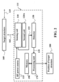
- FIG. 2 shows a block diagram of a sensor 100 of FIG. 1 , for determining a relative position 180 of the target structure 160.
- the target structure 160 and the sensor 100 include flat surfaces facing each other.
- the target structure 160 includes at least one passive resonant structure or passive structure that has resonance at a certain radio frequency f 0 .
- the movement of the target structure 160 can be unrestricted.
- the target structure 160 can move according to a trajectory 125, e.g., in a plane parallel to the flat surface of the sensor 100.
- the sensor 100 includes the sensing coil 110, the second coil 120A and the detector 130.
- the detector 130 may include a detecting structure (not shown).
- the sensing coil 110 can be an electromagnetic structure generating an electromagnetic near-field upon receiving energy, as noted above.
- the sensing coil 110 is an electric current carrying coil.
- the sensing coil 110 can be inductively coupled 122 with the detector 130 and can be integrated onto one dielectric substrate, such that the relative position of the sensing coil 110 and second coil 120A may be fixed.
- the sensing coil 110 can be fed by a radio frequency power source 115.
- the power source 115 can supply the energy to the sensing coil 110 via a power signal having an identical resonance frequency as the target structure 160.
- the target structure 160 can be coupled 162 to the sensing coil 110.
- the magnetic flux Upon receiving the energy, the magnetic flux passes through each coil, sensing coil 110 and second coil 120A, and generates an induced voltage across each coil.
- the induced voltages of the coil pair are recorded by the detector, wherein the detector 130 includes a voltmeter.
- the voltage information is submitted to the processing unit 170 and the magnitudes of the voltages and/or the difference of the voltages is used to determine the position 180 of the target structure 160.
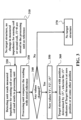
- Figure 3 shows a block diagram of a method for determining the relative position of the target structure according to one embodiment of the present disclosure.
- a measured voltage of V1 of the sensing coil is unchanged.
- a measured voltage of V2 of the second coil can be measured to identify if there is no target structure in the vicinity of the sensing coil or second coil.
- the detector measures V1 of the sensing coil to detect a change in the voltage ( ⁇ V), wherein the information can be stored 330 in the processing unit as a reference value, i.e. reference data.
- the detector can measure V2 of the second coil to detect a change in the voltage ( ⁇ V), wherein the information can be stored in the processing unit as a reference value, i.e. reference data.
- the sensor continuously measures 340 V1 of the sensing coil and/or V2 of the second coil to detect a change in voltage ( ⁇ V), which are sent to the processing unit with stored reference values. If there is no change detected, then there is no target structure in range 370. If there is change in the measured values 350 of either V1 or V2, or both, then these values are analyzed by the processing unit. If either V1 and/or V2 are changed, the new change of voltage ⁇ V' 360 will determine the presence of the target structure along with a position of the target structure within the near field based upon reference values, i.e. reference data.
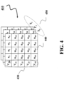
- Some embodiments of the present disclosure are based on the realization that when the magnetic flux induces current through multiple coupled coils, the magnitude and/or change of the voltage of either the sensing coil and/or the second coil are indicative of the relative position of the target structure within the near field based upon reference values, i.e. reference data. For example, a trajectory of potential movement of the target structure can be sampled to determine a voltage of the coils, i.e. sensing coil and/or second coil, corresponding to a specific position of the target structure on the trajectory. Accordingly, some embodiments of the present disclosure determine a mapping between information indicative of a value of the voltages of either one or both of the coils, i.e. sensing coil and/or second coil, as a relative position of the target structure.
- Figure 4 shows an example of the mapping 410 of the values of the voltages 420 of at least one coil, i.e. sensing coil and/or the second coil, and relative positions 440 of the target structure according to some embodiments of the present disclosure.
- the mapping is determined for different positions in space around the sensor.
- the mapping is determined for trajectories 450, e.g., in a plane parallel to the electromagnetic structure of the sensing coil or second coil.
- the detector measures either a first voltage across the sensing coil and/or a second voltage across the second coil, wherein the processor determines a relative position of the target structure with respect to the sensing coil or second coil based on the value of the voltage.
- target structures move according to a trajectory in a plane parallel to the electromagnetic structure of the sensing coil, and the memory 190 stores a mapping of a set of positions of the target structure on the trajectory and a set of values of the measured voltages.
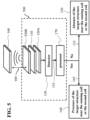
- FIG. 5 shows a schematic of a sensor 500 according to another embodiment of the present disclosure.
- FIG. 5 shows the schematic of sensor 100 of FIG. 1 , however, a third coil 520B, or an additional coil, is arranged in proximity to or adjacent the sensing coil 110, such that the electromagnetic near-field induces, via an inductive coupling, a current passing through sensing coil 110, the second coil 120A and the third coil 520B.
- the third coil 520B induces an increase in the electromagnetic near-field over the induced electromagnetic near-field generated by the sensing coil 110 along with the second coil 120A, among other things.
- At least one effect, among many effects, is that a gap 599 between the target structure 160 and the sensing coil 110, the second coil 120A and the third coil 520B, may be increased over the gap 99 of FIG. 1 , thus allowing for improved operation of the sensor 500.
- the position of the sensing coil 110 may be positioned between the second coil 120A and the third coil 520B, such that the second coil 120A and the third coil 520B are positioned adjacent to or in proximity to the sensing coil 110.
- the second coil 120A may be position symmetrically opposite the third coil 520B in relation to the sensing coil 110.
- the second coil 120A may not be positioned symmetrically opposite the third coil 520B in relation to the sensing coil 110, such that the second coil 120A or third coil 520B can be positioned differently, but still adjacent the sensing coil 110.
- the second coil 120A and the third coil 520B may be positioned on opposite sides of the sensing coil 110 either horizontally or vertically.
- the second coil 120A and the third coil 520B may be positioned on opposite sides of the sensing coil 110, however, at least one coil of the second coil 120A and third coil 520B may be positioned offset to a side of the sensing coil 110.
- the coupling of the target structure 160 changes the shape of the magnetic near-field, which in turn changes the current in the connected coils, i.e. sensing coil 110, second coil 120A and third coil 520B, generated by that near-field, when in proximity of the magnetic field.
- the effect of such a presence is felt within the entire near-field making such detection less sensitive to the distance (i.e. the distance or gap 599 can be increased), between the sensing coil 110 and/or the second coil 120A generating the near-field and the target structure 160.
- the distance is increased or the gap 599 is increased over that of the gap 99 of sensor 100 of FIG. 1 .
- the second coil and third coil when positioned adjacent to the first coil by one of vertically or horizontally relative to a front face of the target structure may include at least 15%, or at least 20%, or at least 30%, of an outer surface area of the second coil and the third coil that is adjacent to an outer surface area of the first coil.
- a percentage of 15% adjacent surface area of the three coils indicates that the coupling coefficient is around 0.15.
- the coupling coefficient in turn is directly related to the amount of impedance change that the second coil and third coil are able to bring.
- FIG. 6A and FIG. 6B show a change in sensing coil impedance as a function of a target structure position.
- FIG. 6A shows a conventional single eddy current coil 11 and a target structure 60. Wherein the conventional eddy current impedance, is shown as a function of the target structure 60 position.
- FIG. 6A shows the target structure 60 being a metal plate, and sliding along one direction as shown in the dotted line with an arrow. Approximately in the middle of the target structure 60 is where a sensing coil 11 is aligned.
- the conventional single eddy current coil 11 without additional coils, results in an impedance change that is less than 1 Ohm.
- FIG. 6B show eddy current coil impedance, as a function of the target position, in accordance with one embodiment.
- FIG. 6B shows an eddy current coil 610 or sensing coil, positioned between a second coil 620A and a third coil 620B, along with a target structure 660.
- the eddy current impedance is shown as a function of the target structure 660 position.
- FIG. 6B shows the target structure 660 being a metal plate, and sliding along one direction as shown in the dotted line with an arrow.
- the pair of coils, the second coil 620A and third coil 620B when placed adjacent to the two sides of the sensing coil 610, and if one were to conduct the same measurement process as completed in FIG. 6A above.
- the measurement result would be over 100 Ohm change in impedance observed in FIG. 6B for the same change in distance as of FIG. 6A .
- the same change in position corresponds to a much larger change in experimentally measurable parameter (impedance) for the system of the present disclosure in FIG. 6B . Therefore, the system of the present disclosure as shown in FIG. 6B , is much easier to detect the position of target structure, and much less susceptible to noise, among other things, over the conventional system of FIG. 6A .
- Impedance of a Coil is a Function of Frequency and Varies Significantly Around Resonance
- FIG. 6C shows a conventional inductive sensor, wherein the target structure is a coil, rather than a metal plate as noted above with the conventional eddy current coil in FIG. 6A .
- FIG. 6D shows the target structure is a coil structure.
- the inductance of a target coil as shown in FIG. 6D is generally much higher than that of the target structure being a metal plate, which causes more significant impedance change than the case of eddy current sensor as shown in FIG. 6B .
- the impedance of a coil is a function of frequency and varies significantly around resonance.
- FIG. 6C shows a conventional inductive coil 11 along with a target structure 61, wherein the target structure is a coil.
- the measurable change is about 17% when the target structure is moving from a position away from the sensing structure 11, to a position aligned with the sensing structure 11.
- FIG. 6D shows an inductive coil 611 positioned between a second coil 621A and a third coil 621B along with a target structure 661, wherein the target structure is a coil, in accordance with one embodiment.
- the pair of coils, the second coil 621A and third coil 621B when added to the sensing coil 611, the observed impedance is much higher than the conventional single inductive coil 11 of FIG. 6C .
- the measurable change is about 50% when the target structure 661 is moving from a position away from the sensing structure 661, to a position aligned with the sensing structure 661.
- the system of the present disclosure of FIG. 6D provides an unexpected result that is significantly over that of the conventional system of FIG. 6C , using the coil structure as the target structure.
- the impedance of a coil is a function of frequency and varies significantly around resonance.
- These induced magnetic fields superimposes onto the magnetic field from the sensing coil 611, causing significant change in impedance.
- the results of the system shown in FIG. 6D is a significant improvement in the process of determining the position of target structure, among other things, over the conventional system of FIG. 6C .
- the same change in position corresponds to a much larger change in experimentally measurable parameter (impedance) for the system of the present disclosure in FIG. 6D . Therefore, the system shown in FIG. 6D , can easier to detect the position of target structure, and is less susceptible to noise, among other things.
- the magnetic field over the frequency spectrum can be modified, at some frequency range, the field strength at target structure coil is enhanced.
- the pair of coil may be parasitic coils or passive coils.
- FIG. 6E shows that the configuration of FIG. 6D having a sensing coil positioned between a second coil and a third coil approximate a coil target structure, results in the spectrum of received signal strength being modified by the pair of coils, the second coil and third coil, due to the additional coupling terms. Wherein, the peak is also higher, indicating stronger coupling to the target coil. Thus, by operating at the peak frequency, it is possible to achieve higher signal strength with the additional coils.
- the sensing coil can be a single turn square loop of copper wire, which is connected to a power source at the two terminals. Further the sensing coil may be a multi-turn copper coil, which can be placed on a printed circuit board as second coil, by non-limiting example. Further still, the sensing coil can be formed by metallic wires of multiple turns, which can be of thin and flat forms as used in printed circuit boards or can be built by stranded wires or Litz wires. The sensing coil can have different geometrical patterns. Noted, is that the second coil and the target coil may be identical as the sensing coil. The second coil may be identical in geometry as the sensing coil, or may be different. The target structure may be a coil having the identical geometry as the sensing coil, or may be a different coil, or may not be in a coil form at all, i.e. metal plate, a slit, etc.
- FIG. 7 is an example of a sensor 700 for eddy current or inductive sensing, according to embodiments of the present disclosure.
- the sensing coil 710 can be a planar multi-turn spiral structure, connected to a capacitor 723B, and excited by a high frequency power source 715.
- one or more additional coils i.e. second coil 720A and third coil 720B, are placed adjacent the excited sensing coil 710.
- the second coil 720A and third coil 720B are tuned to a resonant frequency similar to the sensing coil 710.
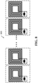
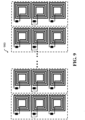
- FIG. 8 and FIG. 9 are examples of multiple sensors of FIG. 7 , the multiple sensors 800, 900 may be for eddy current or inductive sensing, according to embodiments of the present disclosure.
- FIG. 8 shows multiple eddy current sensors or inductive sensors arranged in an array. Each sensor in the array provides a reading depending on the target structure.
- the target structure can be a metal plate of multiple slots in the case of eddy current sensor.
- the target can be multiple coils arranged in an array.
- the position information can be encoded in the target structure. Wherein each sensor in the array provides a reading depending on the relative position to the target structure. Thus a code can be generated by the readings of all sensors in the array.
- a new code can be obtained by the multiple sensing coils.
- the proposed method can also be applied to enhance the performance of each sensor in the array, as shown in Fig. 9 .
- the analog reading is converted to digital signal of 0 or 1, depending on the amplitude of the reading. So at each position, a sensor has a coding bit of 0 or 1.
- each sensor has a different reading, due to that their relative positions to the target structure are different.
- each sensor generates a coding bit of 0 or 1, and by putting the readings together, provides for a result in obtaining a coding sequence at each position.
- the system results in improving signal strength, and a signal-to-noise ratio, so that accuracy can be improved, among other things.
- the set of coils can be an array of coils, wherein energy provided to the array of coils is from at least one power source via a power signal having a resonance frequency.
- the processor detects a presence of a target structure within an array of target structures in proximity to each set of coils of the array of coils upon detecting a change in a value of the voltage.
- each target structure of the array of target structures is an electromagnetic structure moving at a distance from set of coils of the array of coils, such that each set of coils in the array of sensors provides a positional reading depending on a relative position within the array of target structures, wherein a code can be generated by a reading of each one set of coils in the array of sensors.
- the structures can be identical or different designs, and can have identical or different resonant frequencies.
- the induced magnetic field on the target structure is different at different positions, and impacts the induced voltages differently.
- the target structure serves as a scale corresponding to different positions, and can be utilized by the sensor to determine the position information.
- three measurement channels can determine a position of the target structure independently.
- the additional channels can serve as redundancy as the first channel.
- the redundant channels help obtain the correct position information. Because the relative positions between the three measurement channels are known, the multiple channels can also work together and serve as part of a linear encoder.
- the sensor and the method of determining a presence and/or a relative position of a target structure in a proximity to a sensor of this invention are applicable to sensors in many kinds of fields.
Landscapes
- Physics & Mathematics (AREA)
- General Physics & Mathematics (AREA)
- Life Sciences & Earth Sciences (AREA)
- Engineering & Computer Science (AREA)
- Environmental & Geological Engineering (AREA)
- Geology (AREA)
- Remote Sensing (AREA)
- General Life Sciences & Earth Sciences (AREA)
- Geophysics (AREA)
- Transmission And Conversion Of Sensor Element Output (AREA)
- Measurement Of Length, Angles, Or The Like Using Electric Or Magnetic Means (AREA)
Claims (15)
- Sensor, umfassend:einen Spulensatz, wobei der Spulensatz eine erste Spule (110) und eine zweite Spule (120A) umfasst, wobei die erste Spule bei Empfang von Energie ein elektromagnetisches Nahfeld erzeugt, so dass das elektromagnetische Nahfeld zumindest einen Teil der Energie durch induktive Kopplung an die zweite Spule liefert, wodurch ein Strom induziert wird, um durch den Spulensatz zu fließen;einen Detektor (130) zum Messen jeder Spannung an beiden, der ersten Spule und der zweiten Spule; und einen Prozessor (170) zum Erfassen eines Vorhandenseins einer Zielstruktur (160) in der Nähe des Spulensatzes bei Erfassen einer Änderung eines Werts der Spannung;dadurch gekennzeichnet, dassbeide, die erste Spule (110) und die zweite Spule (120A), mit dem Detektor (130) in Kommunikation sind, der Detektor einen Spannungsmesser umfasst, der jede Spannung an beiden, der ersten Spule und der zweiten Spule, erfasst, so dass der Wert der vom Spannungsmesser gemessenen Spannung beide, die erste Spannung an der ersten Spule und die zweite Spannung an der zweiten Spule, darstellt, und wobei der Prozessor eine relative Position der Zielstruktur (160) in Bezug auf die erste Spule auf der Grundlage der Änderung des Wertes der ersten Spannung und eine relative Position der Zielstruktur (160) in Bezug auf die zweite Spule auf der Grundlage der Änderung des Wertes der zweiten Spannung bestimmt.
- Sensor nach Anspruch 1, wobei jede Spule des Spulensatzes (110, 120A) identisch ist, wobei die Zielstruktur (160) eine Zielspule umfasst, die mit jeder Spule in dem Spulensatz identisch ist.
- Sensor nach Anspruch 1, ferner umfassend:
eine Energiequelle (115) zum Zuführen der Energie zu der ersten Spule (110) über ein Energiesignal mit einer Resonanzfrequenz, wobei jede Spule des Spulensatzes (110, 120A) eine elektromagnetische Struktur mit einer Resonanzfrequenz ist. - Sensor nach Anspruch 1, wobei die zweite Spule (120A) eine Resonanzfrequenz hat, die ungefähr einer Resonanzfrequenz der ersten Spule (110) entspricht, so dass die erste Spule eine Sensorspule ist und die zweite Spule eine passive Spule ist.
- Sensor nach Anspruch 1, wobei sich die Zielstruktur (160) gemäß einer Trajektorie in einer Ebene parallel zu einer von der ersten Spule (110), der zweiten Spule (120A) oder beiden, der ersten Spule und der zweiten Spule, bewegt, ferner umfassend:
einen Speicher (190), der eine Zuordnung zwischen einem Satz von Positionen der Zielstruktur auf der Trajektorie und einem Satz von Werten der Spannungen speichert, wobei der Prozessor (170) die relative Position der Zielstruktur (160) unter Verwendung der Zuordnung bestimmt. - Sensor nach Anspruch 1, wobei der Spulensatz (110, 120A) eine identische Form aufweist, so dass eine von der ersten Spannung, der zweiten Spannung oder beide, die erste Spannung und die zweite Spannung unter einem Schwellenwert liegen, wenn sich die Zielstruktur (160) außerhalb des elektromagnetischen Nahfeldes befindet.
- Sensor nach Anspruch 1, wobei der Prozessor (170) die relative Position der Zielstruktur (160), die mit dem Spulensatz auszurichten ist, bestimmt, falls eine Größe von einer von der ersten Spannung, der zweiten Spannung oder beiden, der ersten Spannung und der zweiten Spannung, während des Vorhandenseins der Zielstruktur innerhalb des elektromagnetischen Nahfeldes kleiner oder größer ist als eine Größe von einer von der ersten Spannung, der zweiten Spannung oder beiden, der ersten Spannung und der zweiten Spannung, wenn sich die Zielstruktur außerhalb des elektromagnetischen Nahfeldes befindet.
- Sensor nach Anspruch 1, wobei der Prozessor (170) Größen von einer von der ersten Spannung, der zweiten Spannung oder beiden, der ersten Spannung und der zweiten Spannung, mit Referenzspannungen vergleicht, um ein Vorhandensein der Zielstruktur (160) innerhalb des elektromagnetischen Nahfeldes zu erfassen.
- Sensor nach Anspruch 1, wobei der Spulensatz (110, 120A) eine dritte Spule (520B) umfasst, die dritte Spule und die zweite Spule der ersten Spule benachbart sind, so dass die dritte Spule und die zweite Spule Resonanzfrequenzen aufweisen, die einer Resonanzfrequenz der ersten Spule nahe kommen.
- Sensor nach Anspruch 9, wobei die erste Spule (110) zwischen der zweiten Spule (120A) und der dritten Spule (520B) entweder vertikal oder horizontal relativ zu einer Frontfläche der Zielstruktur positioniert ist, so dass mindestens 15 % eines äußeren Oberflächenbereichs jeder von der zweiten Spule und der dritten Spule einer äußeren Oberfläche der ersten Spule benachbart sind, oder mindestens 20 % eines äußeren Oberflächenbereichs jeder von der zweiten Spule und der dritten Spule der äußeren Oberfläche der ersten Spule benachbart sind, oder mindestens 30 % eines äußeren Oberflächenbereichs jeder von der zweiten Spule und der dritten Spule der äußeren Oberfläche der ersten Spule benachbart sind.
- Sensor nach einem der Ansprüche 1 bis 10, wobei mindestens 10 % eines äußeren Oberflächenbereichs der zweiten Spule einer äußeren Oberfläche der ersten Spule benachbart ist.
- Sensor nach Anspruch 11, wobei mindestens eine Spule des Spulensatzes (110, 120A) ein anderer Spulentyp als die anderen Spulen des Spulensatzes ist, so dass die Zielstruktur (160) eine Spule ist und entweder ein identischer Spulentyp wie der Spulensatz oder ein anderer Spulentyp als der Spulensatz ist.
- Sensor nach Anspruch 1, wobei der Spulensatz (110, 120A) ein Array von Spulen ist, wobei die dem Array von Spulen zugeführte Energie von mindestens einer Energiequelle über ein Energiesignal mit einer Resonanzfrequenz stammt;
wobei der Prozessor (170) ein Vorhandensein einer Zielstruktur innerhalb eines Arrays von Zielstrukturen in der Nähe jedes Spulensatzes des Arrays von Spulen bei Erfassen einer Änderung eines Wertes der Spannung erfasst, wobei jede Zielstruktur des Arrays von Zielstrukturen eine elektromagnetische Struktur ist, die sich in einem Abstand von einem Spulensatz des Arrays von Spulen bewegt, so dass jeder Spulensatz in dem Array von Sensoren eine Positionsablesung in Abhängigkeit von einer relativen Position innerhalb des Arrays von Zielstrukturen liefert, so dass ein Code durch eine Ablesung von jedem einzelnen Spulensatz in dem Array von Sensoren erzeugt wird. - Sensor nach Anspruch 13, wobei bei einer Bewegung der Zielstruktur (160) ein neuer Code durch das Array von Spulen erhalten wird, wobei jede Zielstruktur positionsbezogene Informationen umfasst, die in jeder Zielstruktur des Arrays von Zielstrukturen kodiert sind.
- Verfahren zum Bestimmen eines Vorhandenseins und/oder einer relativen Position einer Zielstruktur (160) in der Nähe eines Sensors, der Sensor einen Spulensatz umfasst, der Spulensatz eine erste Spule (110) und eine zweite Spule (120A) umfasst, so dass die erste Spule bei Empfang von Energie ein elektromagnetisches Nahfeld erzeugt, wobei das elektromagnetische Nahfeld zumindest einen Teil der Energie durch induktive Kopplung an die zweite Spule liefert, wodurch ein Strom induziert wird, um durch den Spulensatz zu fließen, und einen Detektor (130) zum Messen einer ersten Spannung an der ersten Spule und einer zweiten Spannung an der zweiten Spule,
das Verfahren umfassend:Nutzen eines Prozessors (170) zum Erfassen eines Vorhandenseins einer Zielstruktur in der Nähe des Spulensatzes bei Erfassen einer Änderung eines Wertes der gemessenen Spannung, so dass der Wert der gemessenen Spannung sowohl die erste Spannung an der ersten Spule als auch die zweite Spannung an der zweiten Spule darstellt;Aufzeichnen (310), durch den Prozessor, falls es keine Änderung des Wertes der gemessenen Spannung für den Spulensatz gibt, und Speichern in einem Speicher (190), wobei der Speicher mit dem Prozessor in Kommunikation ist;Erfassen (320), durch eine Erfassungseinheit, eines gemessenen Wertes der Spannung des Spulensatzes, und Senden des gemessenen Wertes der Spannung des Spulensatzes an den Prozessor;Vergleichen (330), durch den Prozessor, des gemessenen Wertes der Spannung des Spulensatzes mit historisch gespeicherten Referenzwerten;Bestimmen (340, 370) durch den Prozessor, ob es keine Änderung des Wertes der gemessenen Spannung für den Spulensatz gibt, und falls keine Änderung, dann kein Vorhandensein und/oder keine relative Position der Zielstruktur in der Nähe des Sensors;Bestimmen (340, 350, 360), durch den Prozessor, ob es eine erfasste Änderung des Wertes der gemessenen Spannung für den Spulensatz gibt, bei Bestimmen der erfassten Änderung, die Zielstruktur dann vorhanden ist und eine Position der Zielstruktur durch einen Änderungsbetrag des Wertes der gemessenen Spannung des Spulensatzes bestimmt wird, Angeben, ob sich die Zielstruktur an einer Nullposition oder an einer anderen Position befindet, undeine relative Position der Zielstruktur (160) in Bezug auf die erste Spule auf der Grundlage der Änderung des Werts der ersten Spannung bestimmt ist, und eine relative Position der Zielstruktur (160) in Bezug auf die zweite Spule auf der Grundlage der Änderung des Werts der zweiten Spannung bestimmt ist.
Applications Claiming Priority (2)
| Application Number | Priority Date | Filing Date | Title |
|---|---|---|---|
| US15/210,175 US10288759B2 (en) | 2016-07-14 | 2016-07-14 | Contactless semsor |
| PCT/JP2017/020732 WO2018012140A1 (en) | 2016-07-14 | 2017-05-29 | Contactless sensor |
Publications (2)
| Publication Number | Publication Date |
|---|---|
| EP3485225A1 EP3485225A1 (de) | 2019-05-22 |
| EP3485225B1 true EP3485225B1 (de) | 2024-08-07 |
Family
ID=59215843
Family Applications (1)
| Application Number | Title | Priority Date | Filing Date |
|---|---|---|---|
| EP17733051.1A Active EP3485225B1 (de) | 2016-07-14 | 2017-05-29 | Berührungsfreie sensorik |
Country Status (6)
| Country | Link |
|---|---|
| US (1) | US10288759B2 (de) |
| EP (1) | EP3485225B1 (de) |
| JP (1) | JP6593825B2 (de) |
| KR (1) | KR102184258B1 (de) |
| CN (1) | CN109690232B (de) |
| WO (1) | WO2018012140A1 (de) |
Families Citing this family (9)
| Publication number | Priority date | Publication date | Assignee | Title |
|---|---|---|---|---|
| JP6900771B2 (ja) * | 2017-05-09 | 2021-07-07 | オムロン株式会社 | 近接センサおよび方法 |
| US10760928B1 (en) * | 2019-02-21 | 2020-09-01 | Microsemi Corporation | Planar linear inductive position sensor having edge effect compensation |
| CN110470205B (zh) * | 2019-08-13 | 2021-07-09 | 森泰英格(成都)数控刀具股份有限公司 | 无源线圈感应检测自动识别刀柄的方法 |
| US11502728B2 (en) * | 2019-08-20 | 2022-11-15 | Nxp B.V. | Near-field wireless device for distance measurement |
| CN111168469A (zh) * | 2019-11-12 | 2020-05-19 | 西安邮电大学 | 一种五轴数控机床空间热误差测量系统 |
| CN110974136A (zh) * | 2020-01-03 | 2020-04-10 | 深圳术为科技有限公司 | 一种在位检测装置、冷光源及内窥镜 |
| US12298127B2 (en) * | 2022-02-08 | 2025-05-13 | Semiconductor Components Industries, Llc | Linear inductive position sensor |
| JP7576683B1 (ja) | 2023-11-24 | 2024-10-31 | 株式会社マグネスケール | 位置検出装置 |
| CN119413058B (zh) * | 2025-01-08 | 2025-03-18 | 中国科学技术大学 | 一种非接触式三维位移传感器 |
Family Cites Families (17)
| Publication number | Priority date | Publication date | Assignee | Title |
|---|---|---|---|---|
| DE4311973C2 (de) | 1993-04-14 | 1997-09-11 | Pepperl & Fuchs | Magneto-induktives Sensorsystem für eine magnetische Positions- und/oder Wegbestimmung |
| US6727691B2 (en) | 2000-06-26 | 2004-04-27 | Jentek Sensors, Inc. | High resolution inductive sensor arrays for material and defect characterization of welds |
| JP2005201740A (ja) | 2004-01-14 | 2005-07-28 | Tsubakimoto Chain Co | 物品検査装置及び物品検査方法 |
| US7276897B2 (en) * | 2004-04-09 | 2007-10-02 | Ksr International Co. | Inductive position sensor |
| US7538544B2 (en) * | 2004-04-09 | 2009-05-26 | Ksr Technologies Co. | Inductive position sensor |
| CN100445694C (zh) * | 2004-04-09 | 2008-12-24 | Ksr科技公司 | 感应位置传感器 |
| GB0427410D0 (en) | 2004-12-14 | 2005-01-19 | Kreit Darran | Data acquisition system |
| US7449878B2 (en) | 2005-06-27 | 2008-11-11 | Ksr Technologies Co. | Linear and rotational inductive position sensor |
| DE102006046531A1 (de) * | 2006-09-29 | 2008-04-03 | Dr. Johannes Heidenhain Gmbh | Drehgeber und Verfahren zu dessen Betrieb |
| CN201145720Y (zh) * | 2007-12-29 | 2008-11-05 | 深圳创维-Rgb电子有限公司 | 一种电感线圈极性测量装置 |
| JP5482039B2 (ja) | 2009-09-07 | 2014-04-23 | 富士ゼロックス株式会社 | 検知装置 |
| EP2537451A4 (de) * | 2010-02-18 | 2015-09-16 | Olympus Medical Systems Corp | Positionserkennungssystem und positionserkennungsverfahren |
| DE102011004348A1 (de) * | 2011-02-17 | 2012-08-23 | Beckhoff Automation Gmbh | Verfahren und Positionserfassungsvorrichtung zum Erfassen einer Position eines beweglichen Elements einer Antriebsvorrichtung |
| US8712710B2 (en) * | 2011-05-13 | 2014-04-29 | Honeywell International Inc. | Method and apparatus for detection of LVDT core fallout condition |
| JP2013134227A (ja) | 2011-12-27 | 2013-07-08 | Canon Electronics Inc | 金属検知装置 |
| GB2517152A (en) * | 2013-08-12 | 2015-02-18 | Gde Technology Ltd | Position sensor |
| CN105445809B (zh) * | 2014-08-19 | 2018-09-11 | 清华大学 | 对移动目标进行检查的设备及方法 |
-
2016
- 2016-07-14 US US15/210,175 patent/US10288759B2/en active Active
-
2017
- 2017-05-29 CN CN201780042254.1A patent/CN109690232B/zh active Active
- 2017-05-29 KR KR1020197000561A patent/KR102184258B1/ko active Active
- 2017-05-29 JP JP2018545233A patent/JP6593825B2/ja active Active
- 2017-05-29 WO PCT/JP2017/020732 patent/WO2018012140A1/en not_active Ceased
- 2017-05-29 EP EP17733051.1A patent/EP3485225B1/de active Active
Also Published As
| Publication number | Publication date |
|---|---|
| KR102184258B1 (ko) | 2020-11-30 |
| CN109690232B (zh) | 2020-12-29 |
| EP3485225A1 (de) | 2019-05-22 |
| US10288759B2 (en) | 2019-05-14 |
| WO2018012140A1 (en) | 2018-01-18 |
| US20180017695A1 (en) | 2018-01-18 |
| KR20190014088A (ko) | 2019-02-11 |
| JP6593825B2 (ja) | 2019-10-23 |
| JP2019506618A (ja) | 2019-03-07 |
| CN109690232A (zh) | 2019-04-26 |
Similar Documents
| Publication | Publication Date | Title |
|---|---|---|
| EP3485225B1 (de) | Berührungsfreie sensorik | |
| US10571593B2 (en) | Method for analysing measurement signal of metal sensor and detecting object via metal sensor | |
| CN1332174C (zh) | 多个方向上的距离的无接触测量设备 | |
| CN110657826B (zh) | 用于感应位置编码器的标尺构造 | |
| US11002765B1 (en) | Non-contact voltage sensing method and apparatus | |
| US20110089938A1 (en) | Device and Method for the Detection of Electrically Conducting Objects | |
| US20100201353A1 (en) | Sensor arrangement for a shaft that is mounted in a magnetic bearing | |
| CN109959399A (zh) | 用于感应式位置编码器的绕组和刻度构造 | |
| EP2577337A1 (de) | Spule mit einer wicklung mit einem multiaxialkabel | |
| WO2016157900A1 (en) | Position sensor | |
| GB2528474A (en) | Operation of an inductive power transfer system | |
| US7576532B2 (en) | Motion transducer for motion related to the direction of the axis of an eddy-current displacement sensor | |
| US11567229B2 (en) | Detector for detecting electrically conductive material | |
| KR20000071407A (ko) | 고주파 전류 검출 장치 | |
| JP5139822B2 (ja) | 磁界プローブ | |
| US9329207B2 (en) | Surface current probe | |
| US11060925B2 (en) | Magnetic force sensor and production thereof | |
| JP5290598B2 (ja) | 核磁気共鳴装置とその信号取り出し方法 | |
| EP4471446A1 (de) | Sensoranordnung | |
| JP2019015657A (ja) | 位置検出装置 | |
| CN121219602A (zh) | 传感器布置结构 | |
| WO2006046859A1 (en) | Device for non-destructively examining an object | |
| CN109143403A (zh) | 用于校准感应式定位传感器的方法以及定位传感器 |
Legal Events
| Date | Code | Title | Description |
|---|---|---|---|
| STAA | Information on the status of an ep patent application or granted ep patent |
Free format text: STATUS: UNKNOWN |
|
| STAA | Information on the status of an ep patent application or granted ep patent |
Free format text: STATUS: THE INTERNATIONAL PUBLICATION HAS BEEN MADE |
|
| PUAI | Public reference made under article 153(3) epc to a published international application that has entered the european phase |
Free format text: ORIGINAL CODE: 0009012 |
|
| STAA | Information on the status of an ep patent application or granted ep patent |
Free format text: STATUS: REQUEST FOR EXAMINATION WAS MADE |
|
| 17P | Request for examination filed |
Effective date: 20181109 |
|
| AK | Designated contracting states |
Kind code of ref document: A1 Designated state(s): AL AT BE BG CH CY CZ DE DK EE ES FI FR GB GR HR HU IE IS IT LI LT LU LV MC MK MT NL NO PL PT RO RS SE SI SK SM TR |
|
| AX | Request for extension of the european patent |
Extension state: BA ME |
|
| DAV | Request for validation of the european patent (deleted) | ||
| DAX | Request for extension of the european patent (deleted) | ||
| STAA | Information on the status of an ep patent application or granted ep patent |
Free format text: STATUS: EXAMINATION IS IN PROGRESS |
|
| 17Q | First examination report despatched |
Effective date: 20210421 |
|
| GRAP | Despatch of communication of intention to grant a patent |
Free format text: ORIGINAL CODE: EPIDOSNIGR1 |
|
| STAA | Information on the status of an ep patent application or granted ep patent |
Free format text: STATUS: GRANT OF PATENT IS INTENDED |
|
| RIC1 | Information provided on ipc code assigned before grant |
Ipc: G01D 5/14 20060101ALI20240212BHEP Ipc: H03K 17/95 20060101ALI20240212BHEP Ipc: G01D 5/20 20060101ALI20240212BHEP Ipc: G01B 7/02 20060101AFI20240212BHEP |
|
| INTG | Intention to grant announced |
Effective date: 20240306 |
|
| GRAS | Grant fee paid |
Free format text: ORIGINAL CODE: EPIDOSNIGR3 |
|
| GRAA | (expected) grant |
Free format text: ORIGINAL CODE: 0009210 |
|
| STAA | Information on the status of an ep patent application or granted ep patent |
Free format text: STATUS: THE PATENT HAS BEEN GRANTED |
|
| AK | Designated contracting states |
Kind code of ref document: B1 Designated state(s): AL AT BE BG CH CY CZ DE DK EE ES FI FR GB GR HR HU IE IS IT LI LT LU LV MC MK MT NL NO PL PT RO RS SE SI SK SM TR |
|
| REG | Reference to a national code |
Ref country code: GB Ref legal event code: FG4D |
|
| REG | Reference to a national code |
Ref country code: CH Ref legal event code: EP |
|
| REG | Reference to a national code |
Ref country code: IE Ref legal event code: FG4D |
|
| REG | Reference to a national code |
Ref country code: DE Ref legal event code: R096 Ref document number: 602017083883 Country of ref document: DE |
|
| REG | Reference to a national code |
Ref country code: LT Ref legal event code: MG9D |
|
| REG | Reference to a national code |
Ref country code: NL Ref legal event code: MP Effective date: 20240807 |
|
| PG25 | Lapsed in a contracting state [announced via postgrant information from national office to epo] |
Ref country code: NO Free format text: LAPSE BECAUSE OF FAILURE TO SUBMIT A TRANSLATION OF THE DESCRIPTION OR TO PAY THE FEE WITHIN THE PRESCRIBED TIME-LIMIT Effective date: 20241107 |
|
| REG | Reference to a national code |
Ref country code: AT Ref legal event code: MK05 Ref document number: 1711388 Country of ref document: AT Kind code of ref document: T Effective date: 20240807 |
|
| PG25 | Lapsed in a contracting state [announced via postgrant information from national office to epo] |
Ref country code: PT Free format text: LAPSE BECAUSE OF FAILURE TO SUBMIT A TRANSLATION OF THE DESCRIPTION OR TO PAY THE FEE WITHIN THE PRESCRIBED TIME-LIMIT Effective date: 20241209 Ref country code: FI Free format text: LAPSE BECAUSE OF FAILURE TO SUBMIT A TRANSLATION OF THE DESCRIPTION OR TO PAY THE FEE WITHIN THE PRESCRIBED TIME-LIMIT Effective date: 20240807 Ref country code: NL Free format text: LAPSE BECAUSE OF FAILURE TO SUBMIT A TRANSLATION OF THE DESCRIPTION OR TO PAY THE FEE WITHIN THE PRESCRIBED TIME-LIMIT Effective date: 20240807 Ref country code: PL Free format text: LAPSE BECAUSE OF FAILURE TO SUBMIT A TRANSLATION OF THE DESCRIPTION OR TO PAY THE FEE WITHIN THE PRESCRIBED TIME-LIMIT Effective date: 20240807 Ref country code: GR Free format text: LAPSE BECAUSE OF FAILURE TO SUBMIT A TRANSLATION OF THE DESCRIPTION OR TO PAY THE FEE WITHIN THE PRESCRIBED TIME-LIMIT Effective date: 20241108 |
|
| PG25 | Lapsed in a contracting state [announced via postgrant information from national office to epo] |
Ref country code: BG Free format text: LAPSE BECAUSE OF FAILURE TO SUBMIT A TRANSLATION OF THE DESCRIPTION OR TO PAY THE FEE WITHIN THE PRESCRIBED TIME-LIMIT Effective date: 20240807 |
|
| PG25 | Lapsed in a contracting state [announced via postgrant information from national office to epo] |
Ref country code: LV Free format text: LAPSE BECAUSE OF FAILURE TO SUBMIT A TRANSLATION OF THE DESCRIPTION OR TO PAY THE FEE WITHIN THE PRESCRIBED TIME-LIMIT Effective date: 20240807 |
|
| PG25 | Lapsed in a contracting state [announced via postgrant information from national office to epo] |
Ref country code: AT Free format text: LAPSE BECAUSE OF FAILURE TO SUBMIT A TRANSLATION OF THE DESCRIPTION OR TO PAY THE FEE WITHIN THE PRESCRIBED TIME-LIMIT Effective date: 20240807 Ref country code: IS Free format text: LAPSE BECAUSE OF FAILURE TO SUBMIT A TRANSLATION OF THE DESCRIPTION OR TO PAY THE FEE WITHIN THE PRESCRIBED TIME-LIMIT Effective date: 20241207 |
|
| PG25 | Lapsed in a contracting state [announced via postgrant information from national office to epo] |
Ref country code: HR Free format text: LAPSE BECAUSE OF FAILURE TO SUBMIT A TRANSLATION OF THE DESCRIPTION OR TO PAY THE FEE WITHIN THE PRESCRIBED TIME-LIMIT Effective date: 20240807 |
|
| PG25 | Lapsed in a contracting state [announced via postgrant information from national office to epo] |
Ref country code: RS Free format text: LAPSE BECAUSE OF FAILURE TO SUBMIT A TRANSLATION OF THE DESCRIPTION OR TO PAY THE FEE WITHIN THE PRESCRIBED TIME-LIMIT Effective date: 20241107 Ref country code: ES Free format text: LAPSE BECAUSE OF FAILURE TO SUBMIT A TRANSLATION OF THE DESCRIPTION OR TO PAY THE FEE WITHIN THE PRESCRIBED TIME-LIMIT Effective date: 20240807 |
|
| PG25 | Lapsed in a contracting state [announced via postgrant information from national office to epo] |
Ref country code: RS Free format text: LAPSE BECAUSE OF FAILURE TO SUBMIT A TRANSLATION OF THE DESCRIPTION OR TO PAY THE FEE WITHIN THE PRESCRIBED TIME-LIMIT Effective date: 20241107 Ref country code: PT Free format text: LAPSE BECAUSE OF FAILURE TO SUBMIT A TRANSLATION OF THE DESCRIPTION OR TO PAY THE FEE WITHIN THE PRESCRIBED TIME-LIMIT Effective date: 20241209 Ref country code: PL Free format text: LAPSE BECAUSE OF FAILURE TO SUBMIT A TRANSLATION OF THE DESCRIPTION OR TO PAY THE FEE WITHIN THE PRESCRIBED TIME-LIMIT Effective date: 20240807 Ref country code: NO Free format text: LAPSE BECAUSE OF FAILURE TO SUBMIT A TRANSLATION OF THE DESCRIPTION OR TO PAY THE FEE WITHIN THE PRESCRIBED TIME-LIMIT Effective date: 20241107 Ref country code: NL Free format text: LAPSE BECAUSE OF FAILURE TO SUBMIT A TRANSLATION OF THE DESCRIPTION OR TO PAY THE FEE WITHIN THE PRESCRIBED TIME-LIMIT Effective date: 20240807 Ref country code: LV Free format text: LAPSE BECAUSE OF FAILURE TO SUBMIT A TRANSLATION OF THE DESCRIPTION OR TO PAY THE FEE WITHIN THE PRESCRIBED TIME-LIMIT Effective date: 20240807 Ref country code: IS Free format text: LAPSE BECAUSE OF FAILURE TO SUBMIT A TRANSLATION OF THE DESCRIPTION OR TO PAY THE FEE WITHIN THE PRESCRIBED TIME-LIMIT Effective date: 20241207 Ref country code: HR Free format text: LAPSE BECAUSE OF FAILURE TO SUBMIT A TRANSLATION OF THE DESCRIPTION OR TO PAY THE FEE WITHIN THE PRESCRIBED TIME-LIMIT Effective date: 20240807 Ref country code: GR Free format text: LAPSE BECAUSE OF FAILURE TO SUBMIT A TRANSLATION OF THE DESCRIPTION OR TO PAY THE FEE WITHIN THE PRESCRIBED TIME-LIMIT Effective date: 20241108 Ref country code: FI Free format text: LAPSE BECAUSE OF FAILURE TO SUBMIT A TRANSLATION OF THE DESCRIPTION OR TO PAY THE FEE WITHIN THE PRESCRIBED TIME-LIMIT Effective date: 20240807 Ref country code: ES Free format text: LAPSE BECAUSE OF FAILURE TO SUBMIT A TRANSLATION OF THE DESCRIPTION OR TO PAY THE FEE WITHIN THE PRESCRIBED TIME-LIMIT Effective date: 20240807 Ref country code: BG Free format text: LAPSE BECAUSE OF FAILURE TO SUBMIT A TRANSLATION OF THE DESCRIPTION OR TO PAY THE FEE WITHIN THE PRESCRIBED TIME-LIMIT Effective date: 20240807 Ref country code: AT Free format text: LAPSE BECAUSE OF FAILURE TO SUBMIT A TRANSLATION OF THE DESCRIPTION OR TO PAY THE FEE WITHIN THE PRESCRIBED TIME-LIMIT Effective date: 20240807 |
|
| PG25 | Lapsed in a contracting state [announced via postgrant information from national office to epo] |
Ref country code: DK Free format text: LAPSE BECAUSE OF FAILURE TO SUBMIT A TRANSLATION OF THE DESCRIPTION OR TO PAY THE FEE WITHIN THE PRESCRIBED TIME-LIMIT Effective date: 20240807 Ref country code: RO Free format text: LAPSE BECAUSE OF FAILURE TO SUBMIT A TRANSLATION OF THE DESCRIPTION OR TO PAY THE FEE WITHIN THE PRESCRIBED TIME-LIMIT Effective date: 20240807 Ref country code: SM Free format text: LAPSE BECAUSE OF FAILURE TO SUBMIT A TRANSLATION OF THE DESCRIPTION OR TO PAY THE FEE WITHIN THE PRESCRIBED TIME-LIMIT Effective date: 20240807 |
|
| PG25 | Lapsed in a contracting state [announced via postgrant information from national office to epo] |
Ref country code: EE Free format text: LAPSE BECAUSE OF FAILURE TO SUBMIT A TRANSLATION OF THE DESCRIPTION OR TO PAY THE FEE WITHIN THE PRESCRIBED TIME-LIMIT Effective date: 20240807 |
|
| PG25 | Lapsed in a contracting state [announced via postgrant information from national office to epo] |
Ref country code: CZ Free format text: LAPSE BECAUSE OF FAILURE TO SUBMIT A TRANSLATION OF THE DESCRIPTION OR TO PAY THE FEE WITHIN THE PRESCRIBED TIME-LIMIT Effective date: 20240807 |
|
| PG25 | Lapsed in a contracting state [announced via postgrant information from national office to epo] |
Ref country code: SK Free format text: LAPSE BECAUSE OF FAILURE TO SUBMIT A TRANSLATION OF THE DESCRIPTION OR TO PAY THE FEE WITHIN THE PRESCRIBED TIME-LIMIT Effective date: 20240807 |
|
| REG | Reference to a national code |
Ref country code: DE Ref legal event code: R097 Ref document number: 602017083883 Country of ref document: DE |
|
| PLBE | No opposition filed within time limit |
Free format text: ORIGINAL CODE: 0009261 |
|
| STAA | Information on the status of an ep patent application or granted ep patent |
Free format text: STATUS: NO OPPOSITION FILED WITHIN TIME LIMIT |
|
| PGFP | Annual fee paid to national office [announced via postgrant information from national office to epo] |
Ref country code: DE Payment date: 20250402 Year of fee payment: 9 |
|
| PGFP | Annual fee paid to national office [announced via postgrant information from national office to epo] |
Ref country code: GB Payment date: 20250401 Year of fee payment: 9 |
|
| 26N | No opposition filed |
Effective date: 20250508 |
|
| PGFP | Annual fee paid to national office [announced via postgrant information from national office to epo] |
Ref country code: FR Payment date: 20250401 Year of fee payment: 9 |
|
| PG25 | Lapsed in a contracting state [announced via postgrant information from national office to epo] |
Ref country code: SE Free format text: LAPSE BECAUSE OF FAILURE TO SUBMIT A TRANSLATION OF THE DESCRIPTION OR TO PAY THE FEE WITHIN THE PRESCRIBED TIME-LIMIT Effective date: 20240807 |
|
| P01 | Opt-out of the competence of the unified patent court (upc) registered |
Free format text: CASE NUMBER: UPC_APP_4857_3485225/2025 Effective date: 20250827 |