EP3485102B1 - Automatic floor cleaning machine and process - Google Patents
Automatic floor cleaning machine and process Download PDFInfo
- Publication number
- EP3485102B1 EP3485102B1 EP17828335.4A EP17828335A EP3485102B1 EP 3485102 B1 EP3485102 B1 EP 3485102B1 EP 17828335 A EP17828335 A EP 17828335A EP 3485102 B1 EP3485102 B1 EP 3485102B1
- Authority
- EP
- European Patent Office
- Prior art keywords
- unit
- mobile unit
- floor
- recovery
- fixable
- Prior art date
- Legal status (The legal status is an assumption and is not a legal conclusion. Google has not performed a legal analysis and makes no representation as to the accuracy of the status listed.)
- Active
Links
Images









Classifications
-
- E—FIXED CONSTRUCTIONS
- E03—WATER SUPPLY; SEWERAGE
- E03D—WATER-CLOSETS OR URINALS WITH FLUSHING DEVICES; FLUSHING VALVES THEREFOR
- E03D9/00—Sanitary or other accessories for lavatories ; Devices for cleaning or disinfecting the toilet room or the toilet bowl; Devices for eliminating smells
- E03D9/002—Automatic cleaning devices
-
- A—HUMAN NECESSITIES
- A47—FURNITURE; DOMESTIC ARTICLES OR APPLIANCES; COFFEE MILLS; SPICE MILLS; SUCTION CLEANERS IN GENERAL
- A47L—DOMESTIC WASHING OR CLEANING; SUCTION CLEANERS IN GENERAL
- A47L11/00—Machines for cleaning floors, carpets, furniture, walls, or wall coverings
- A47L11/29—Floor-scrubbing machines characterised by means for taking-up dirty liquid
- A47L11/30—Floor-scrubbing machines characterised by means for taking-up dirty liquid by suction
-
- A—HUMAN NECESSITIES
- A47—FURNITURE; DOMESTIC ARTICLES OR APPLIANCES; COFFEE MILLS; SPICE MILLS; SUCTION CLEANERS IN GENERAL
- A47L—DOMESTIC WASHING OR CLEANING; SUCTION CLEANERS IN GENERAL
- A47L11/00—Machines for cleaning floors, carpets, furniture, walls, or wall coverings
- A47L11/40—Parts or details of machines not provided for in groups A47L11/02 - A47L11/38, or not restricted to one of these groups, e.g. handles, arrangements of switches, skirts, buffers, levers
- A47L11/4011—Regulation of the cleaning machine by electric means; Control systems and remote control systems therefor
-
- A—HUMAN NECESSITIES
- A47—FURNITURE; DOMESTIC ARTICLES OR APPLIANCES; COFFEE MILLS; SPICE MILLS; SUCTION CLEANERS IN GENERAL
- A47L—DOMESTIC WASHING OR CLEANING; SUCTION CLEANERS IN GENERAL
- A47L11/00—Machines for cleaning floors, carpets, furniture, walls, or wall coverings
- A47L11/40—Parts or details of machines not provided for in groups A47L11/02 - A47L11/38, or not restricted to one of these groups, e.g. handles, arrangements of switches, skirts, buffers, levers
- A47L11/4013—Contaminants collecting devices, i.e. hoppers, tanks or the like
- A47L11/4016—Contaminants collecting devices, i.e. hoppers, tanks or the like specially adapted for collecting fluids
-
- A—HUMAN NECESSITIES
- A47—FURNITURE; DOMESTIC ARTICLES OR APPLIANCES; COFFEE MILLS; SPICE MILLS; SUCTION CLEANERS IN GENERAL
- A47L—DOMESTIC WASHING OR CLEANING; SUCTION CLEANERS IN GENERAL
- A47L11/00—Machines for cleaning floors, carpets, furniture, walls, or wall coverings
- A47L11/40—Parts or details of machines not provided for in groups A47L11/02 - A47L11/38, or not restricted to one of these groups, e.g. handles, arrangements of switches, skirts, buffers, levers
- A47L11/4036—Parts or details of the surface treating tools
- A47L11/4041—Roll shaped surface treating tools
-
- A—HUMAN NECESSITIES
- A47—FURNITURE; DOMESTIC ARTICLES OR APPLIANCES; COFFEE MILLS; SPICE MILLS; SUCTION CLEANERS IN GENERAL
- A47L—DOMESTIC WASHING OR CLEANING; SUCTION CLEANERS IN GENERAL
- A47L11/00—Machines for cleaning floors, carpets, furniture, walls, or wall coverings
- A47L11/40—Parts or details of machines not provided for in groups A47L11/02 - A47L11/38, or not restricted to one of these groups, e.g. handles, arrangements of switches, skirts, buffers, levers
- A47L11/4036—Parts or details of the surface treating tools
- A47L11/4044—Vacuuming or pick-up tools; Squeegees
-
- A—HUMAN NECESSITIES
- A47—FURNITURE; DOMESTIC ARTICLES OR APPLIANCES; COFFEE MILLS; SPICE MILLS; SUCTION CLEANERS IN GENERAL
- A47L—DOMESTIC WASHING OR CLEANING; SUCTION CLEANERS IN GENERAL
- A47L11/00—Machines for cleaning floors, carpets, furniture, walls, or wall coverings
- A47L11/40—Parts or details of machines not provided for in groups A47L11/02 - A47L11/38, or not restricted to one of these groups, e.g. handles, arrangements of switches, skirts, buffers, levers
- A47L11/408—Means for supplying cleaning or surface treating agents
- A47L11/4083—Liquid supply reservoirs; Preparation of the agents, e.g. mixing devices
-
- A—HUMAN NECESSITIES
- A47—FURNITURE; DOMESTIC ARTICLES OR APPLIANCES; COFFEE MILLS; SPICE MILLS; SUCTION CLEANERS IN GENERAL
- A47L—DOMESTIC WASHING OR CLEANING; SUCTION CLEANERS IN GENERAL
- A47L11/00—Machines for cleaning floors, carpets, furniture, walls, or wall coverings
- A47L11/40—Parts or details of machines not provided for in groups A47L11/02 - A47L11/38, or not restricted to one of these groups, e.g. handles, arrangements of switches, skirts, buffers, levers
- A47L11/408—Means for supplying cleaning or surface treating agents
- A47L11/4088—Supply pumps; Spraying devices; Supply conduits
-
- A—HUMAN NECESSITIES
- A47—FURNITURE; DOMESTIC ARTICLES OR APPLIANCES; COFFEE MILLS; SPICE MILLS; SUCTION CLEANERS IN GENERAL
- A47L—DOMESTIC WASHING OR CLEANING; SUCTION CLEANERS IN GENERAL
- A47L11/00—Machines for cleaning floors, carpets, furniture, walls, or wall coverings
- A47L11/40—Parts or details of machines not provided for in groups A47L11/02 - A47L11/38, or not restricted to one of these groups, e.g. handles, arrangements of switches, skirts, buffers, levers
- A47L11/4091—Storing or parking devices, arrangements therefor; Means allowing transport of the machine when it is not being used
-
- A—HUMAN NECESSITIES
- A47—FURNITURE; DOMESTIC ARTICLES OR APPLIANCES; COFFEE MILLS; SPICE MILLS; SUCTION CLEANERS IN GENERAL
- A47L—DOMESTIC WASHING OR CLEANING; SUCTION CLEANERS IN GENERAL
- A47L2201/00—Robotic cleaning machines, i.e. with automatic control of the travelling movement or the cleaning operation
- A47L2201/04—Automatic control of the travelling movement; Automatic obstacle detection
-
- A—HUMAN NECESSITIES
- A47—FURNITURE; DOMESTIC ARTICLES OR APPLIANCES; COFFEE MILLS; SPICE MILLS; SUCTION CLEANERS IN GENERAL
- A47L—DOMESTIC WASHING OR CLEANING; SUCTION CLEANERS IN GENERAL
- A47L2201/00—Robotic cleaning machines, i.e. with automatic control of the travelling movement or the cleaning operation
- A47L2201/06—Control of the cleaning action for autonomous devices; Automatic detection of the surface condition before, during or after cleaning
Definitions
- This invention generally relates to automatic floor cleaning machines.
- U.S. Patent Publication 2015/0033496 and related U.S. Patent No. 8,887,340 disclose a mobile floor cleaning apparatus with a chassis supported by a plurality of wheels with one steerable via a steering wheel interconnected to a housing, wherein the chassis has a plurality of movable housing members to operate in tight spaces.
- U.S. Patent No. 8,448,293 discloses a mobile wet extractor floor brush adapted for movement on a surface being cleaned having a base assembly for movement on the surface, an operating handle for controlling the movement of the wet extractor pivotally attached to the base assembly, a supply tank having an outlet, a recovery tank having an inlet and an outlet, and an agitator.
- U.S. Patent No. 6,370,453 discloses a self-moving service robot for automatic examination of floor surfaces and for suction of dust from floor surfaces that is programed to explore areas and detect potential obstacles using sensors.
- U.S. Patent No. 5,199,996 discloses a mobile apparatus for cleaning floors having a cleaning device placed on a first side of the apparatus to perform cleaning perpendicular to the general direction of advance of the apparatus.
- U.S. Patent No. 5,012,886 discloses a self-guided mobile unit and cleaning apparatus that follows guides such as walls or other obstacles, engages the guides with a detector element and controls the steering of the apparatus in response to the level of forces sensed by the detector.
- U.S. Patent No. 3,401,420 discloses a vacuum cleaner mounted to a maid's cart but rotatable around a vertical axis for winding of the vacuum hose and cord storage to facilitate cleaning while the vacuum cleaner remains on the maid's cart.
- JP6136809 discloses a toilet divided into two parts, an under floor toilet bowl body and a floor cover above the floor, wherein the floor cover is cleaned in a cleaning chamber provided on the toilet booth side while the floor surface is cleaned with a brush-cleaning device or the like.
- U.S. Patent Publication 2013-0092190 discloses a robot cleaner that travels on a floor with an obstacle sensing unit and an auxiliary cleaning unit mounted to the bottom of the robot body, such that the auxiliary cleaning unit is extendable or retractable when an obstacle is sensed.
- U.S. Patent Publication 2013-0175802 discloses a powered apparatus for fluid applications having a housing dimensioned and configured for mounting in a fluid conduit.
- U.S. Patent No. 8,122,555 discloses a mobile floor cleaning apparatus capable of maximizing a user's convenience by an automatic operation, minimizing jolt or vibration and realizing enhanced endurance and safety with first and second movable members rectilinearly reciprocating along the same straight line in opposite directions with each other.
- WIPO Publication WO 2004-017805 discloses a mobile floor cleaning apparatus with at least one tool that impinges on the floor, at least one vapor outlet, and at least one cleaner outlet.
- U.S. Patent No. 5,628,086 discloses a mobile floor cleaning apparatus with four wheels, two of which are steerable by a steering wheel, to permit tight turns.
- JP 2005213785 discloses a floor cleaning device provided with a moving means for linearly reciprocating a cleaner equipped with a wash water sprinkling means for sprinkling wash water on the floor face and a wiping means for rubbing the floor face, between a stand-by position and the floor face around a urinal through a space between the urinal and a floor; and an electronic control device for giving commands to the cleaner and the moving means to perform cleaning work.
- JP 2010099401 discloses a floor surface cleaner including a cleaning water tank; a rotary brush; a squeezer; a vacuum machine; and a soil water tank.
- the present disclosure relates to an automatic floor cleaner and recovery unit comprising a cleaning and recovery unit wherein the cleaning and recovery unit comprises a fixed unit, a mobile unit, and an extension mechanism connected to the fixed unit and the mobile unit to permit the extension and retraction of the mobile unit from and to the fixed unit.
- the present disclosure further relates to an automatic floor cleaner and recovery unit
- the fixed unit comprises a controller, a sensor, a motor, a power source, a disinfectant solution tank, a vacuum, and a recovery tank
- the fixed unit is mounted to a floor or wall in proximity to a urinal, toilet, sink, or hand drying device
- the controller and the sensor control the activation of the motor for the extension or retraction of the mobile unit
- the power source is AC or DC
- the sensor is mounted on the exterior of the cleaning and recovery unit with a line of view in the direction of a target area of floor, and, alternatively, wherein the sensor is mounted on a urinal, toilet, sink, or hand drying device
- the disinfectant solution tank is connected by tubing to the mobile unit for spraying disinfectant solution onto a target area of floor upon extension of the mobile unit from the fixed unit; wherein the timing of spraying disinfectant solution is controlled by the controller
- the vacuum further comprises its own collection tank, fan, motor, and exhaust port
- the present disclosure relates to a method of automatically cleaning a floor surface using a cleaning and recovery unit comprising the steps of (a) activating a sensor, (b) extending a mobile unit, (c) spraying disinfectant solution onto a target area of floor during extension of the mobile unit, (d) contacting the mobile unit with the floor, and (e) retracting the mobile unit over the target area.
- the present disclosure further relates to a method of automatically cleaning a floor surface, wherein the step of retracting the mobile unit further comprises the steps of scraping and suctioning; wherein the step of activating a sensor is replaced by activation on a timed basis; and wherein the step of retracting is replaced by spraying disinfectant solution onto a target area of floor during retraction of the mobile unit.
- the present disclosure relates to an automatic floor cleaner comprising a cleaning unit, wherein the cleaning unit comprises a fixed unit, a mobile unit, and an extension mechanism connected to the fixed unit and the mobile unit to permit the extension and retraction of the mobile unit from and to the fixed unit; wherein the fixed unit comprises a controller, a sensor, a motor, a power source, and a disinfectant solution tank; wherein the disinfectant solution tank is connected by tubing to the mobile unit for spraying disinfectant solution onto a target area of floor upon extension of the mobile unit from the fixed unit.
- the present disclosure relates to a method of automatically cleaning a floor surface, comprising the steps of (a) activating the sensor, (b) extending the mobile unit, (c) spraying disinfectant solution onto the target area of floor during extension of the mobile unit, and (d) retracting the mobile unit.
- the present disclosure further relates to a method of automatically cleaning a floor surface, wherein the mobile unit is extended on a timed delay at predetermined time periods after the sensor is activated.
- the inventor of the present application has recognized that there is a need for automatic floor cleaning machines, particularly in commercial, industrial, and institutional venues.
- An automatic floor cleaning and recovery unit in accordance with the present invention comprises a fixed unit, a mobile unit, an extension mechanism connected to the fixed unit and the mobile unit to permit the extension and retraction of the mobile unit from and to the fixed unit.
- the automatic floor cleaning and recovery unit may be wall-mounted or floor-mounted adjacent to a wall-mounted or floor-mounted urinal, adjacent to a wall-mounted or floor-mounted toilet, adjacent to a wall-mounted or floor-mounted sink, or adjacent to a wall-mounted or floor-mounted hand drying device.
- the fixed unit is housed within a lavatory appliance, such as a urinal, toilet, sink, or hand drying device.
- the fixed unit is a cartridge that is insertable and removable from a cavity in the urinal, toilet, sink, or hand drying device. In further, non-limiting alternative embodiments, the fixed unit is integrated into a urinal, toilet, sink, or hand drying device.
- the fixed unit comprises a controller, a sensor, a motor, a power source, a disinfectant solution tank, a vacuum, and a recovery tank.
- the fixed unit is positioned in proximity to a target area of a floor or surface for cleaning.
- the controller and the sensor control the activation of the motor for the extension and retraction of the mobile unit.
- the sensor is preferably mounted on the exterior of the cleaning and recovery unit with a line of view in the direction of a target area of floor or surface to be cleaned.
- the sensor may be mounted adjacent to the fixed unit or adjacent to the lavatory appliance.
- the sensor optionally is mounted on the adjacent urinal, toilet, sink, or hand drying device.
- the controller of the fixed unit uses the sensor of the adjacent lavatory appliance.
- the cleaning and recovery unit may also be designed to synchronize with the sensor of the adjacent lavatory appliance.
- the power source can be either AC or DC.
- the cleaning and recovery unit can be plugged into standard electrical outlets or wired directly to an electrical source. For areas that do not have electrical outlets or do not have electrical outlets in a convenient location, the cleaning and recovery unit can be powered by a battery.
- the battery source may be rechargeable or disposable.
- the cleaning and recovery unit can also be powered by the urinal, toilet, sink, or hand drying device, either when wall or floor-mounted or when housed within or integrated into the urinal, toilet, sink, or hand drying device.
- the disinfectant solution tank is housed in the fixed unit and is connected by tubing to the mobile unit for spraying disinfectant solution onto the target area of floor upon extension of the mobile unit from the fixed unit.
- the disinfectant solution tank is not housed inside the fixed unit but is wall-mounted next to and connected to the fixed unit by way of tubing. This would provide additional space in the fixed unit for a larger recovery tank, allow additional space for a larger disinfectant solution tank, and decrease the possibility of any confusion during maintenance of the disinfectant solution tank and the recovery tank.
- the timing of spraying disinfectant solution is controlled by the controller.
- the disinfectant solution tank may have a port for external filling of additional disinfectant solution.
- the disinfectant solution tank is a detachable cartridge or bag that can be replaced as needed.
- a window or other indicator is provided on the exterior of the disinfectant solution tank and the fixed unit so that the level of disinfectant solution is visible or otherwise indicated.
- the disinfectant solution tank preferably contains a liquid cleaner for household, commercial, industrial, and institutional use, and, optionally, has anti-bacterial, anti-microbial and/or anti-viral properties. It is also preferable that the liquid cleaner be quick drying.
- a vacuum Upon retraction of the mobile unit to the fixed unit, a vacuum recovers any waste solution and/or debris.
- the vacuum in the fixed unit has its own collection tank, fan, motor, and exhaust port.
- the vacuum is connected by tubing to the mobile unit for the recovery of waste solution and/or debris from the target area during retraction of the mobile unit to the fixed unit.
- the timing of the vacuum is controlled by the controller.
- the vacuum collection tank is connected by tubing to the recovery tank or an external drain.
- the recovery tank is designed to receive the waste solution and/or debris collected by the vacuum.
- the recovery tank can be removable from the fixed unit for emptying and replacement into the fixed unit.
- the recovery tank is removable for disposable and replaced with a new recovery tank.
- the recovery tank is disposable and contains absorbent material/particles.
- the recovery tank is external to the fixed unit and connected by tubing to the fixed unit.
- the recovery tank is connected to an external drain or replaced by tubing directly to the external drain.
- a window or other indicator is provided on the exterior of the fixed unit and the recovery tank so that the level of waste solution is visible or otherwise indicated.
- the fixed unit has one or more top opening lids for access to all or some of the internal components, such as the disinfectant solution tank, the recovery tank, and/or optional battery.
- the fixed unit has front access ports for access to all or some of the internal components, such as the disinfectant solution tank, the recovery tank, and/or optional battery.
- the internal components of the cleaning and recovery unit are accessed by a panel on the urinal, toilet, sink, or hand drying device.
- the mobile unit comprises spray port(s) for spraying disinfectant solution onto the target area and a scraping implement, like one or more squeegee, for contacting the target area of floor and collecting the waste solution and/or debris from the target area upon retraction of the mobile unit to the fixed unit.
- the mobile unit also contains recovery vacuum port(s) for suctioning waste solution and/or debris from the target area during retraction of the mobile unit to the fixed unit.
- the mobile unit also contains a brush wherein the brush is either fixed or moves by rotating or spinning.
- the mobile unit sprays disinfectant solution onto the target area upon extension of the mobile unit from the fixed unit.
- the scraping implement contacts the target area of the floor upon extension of the mobile unit thereby pushing the waste solution and/or debris from the target area to a floor drain or floor-mounted urinal drain basin.
- the vacuum ports may be located on the bottom of the mobile unit at positions proximal to the fixed unit and distal to the scraping implement, and/or distal to the fixed unit and proximal to the scraping implement depending on the design.
- the disinfectant solution spray ports may be located on the bottom of the mobile unit at positions distal to the fixed unit and proximal to the scraping implement, and/or proximal to the fixed unit and distal to the scraping implement depending on the design.
- the scraping implement preferably has two arcs of squeegee to enhance the capture capability of the mobile unit.
- the arcs may be convex or concave depending on the design.
- the extension mechanism is powered by the motor housed in the fixed unit. According to a non-limiting embodiment of the invention, upon activation by the controller, the extension mechanism first lifts and then extends the mobile unit. Upon initiation of the extension of the mobile unit, the controller then activates the spraying of disinfectant solution over the target area.
- the extension mechanism supports, either internally or externally, the disinfectant solution tubing that connects the disinfectant solution tank to the mobile unit disinfectant port(s). In alternative non-limiting embodiments of the invention, the extension mechanism also supports, either internally or externally, the vacuum tubing that connects the vacuum collection tank to the recovery port(s) on the mobile unit. Upon retraction of the mobile unit, the extension mechanism first drops and then retracts the mobile unit.
- the mobile unit is extended from the fixed unit by the extension mechanism in a raised position and when fully extended the extension mechanism drops the mobile unit into a lowered position to contact the surface of the floor.
- the scraping elements of the mobile unit are in contact with the floor as the mobile unit is retracted back to the fixed unit.
- the mobile unit has one or more wheels that support the mobile unit and roll on the floor during the extension and retraction of the mobile unit.
- the mobile unit has at least two wheels.
- the mobile unit has two forward wheels distal to the fixed unit and two rearward wheels proximal to the fixed unit.
- the forward wheels are raised on extension of the mobile unit, which pivots the mobile unit upward so that it does not contact the floor on extension, and lowered on retraction of the mobile unit, which pivots the mobile unit downward to come in contact with the floor on retraction.
- the forward wheels and rearward wheels are in contact with the floor on extension of the mobile unit. Then the rearward wheels are raised to bring the scraping elements of the mobile unit in contact with the floor on retraction. In other alternative non-limiting embodiments of the invention, the forward wheels are raised on extension of the mobile unit and the rearward wheels are raised on retraction of the mobile unit in order to keep the scraping elements above the surface of the floor on extension of the mobile unit and to bring the scraping elements in contact with the surface of the floor on retraction of the mobile unit.
- an automatic floor cleaning unit in accordance with the present invention is mounted to the floor adjacent to a traditional floor-mounted urinal.
- the cleaning unit comprises a fixed unit, a mobile unit, and an extension mechanism connected to the fixed unit and the mobile unit to permit the extension and retraction of the mobile unit from and to the fixed unit.
- the fixed unit comprises a controller, a sensor, a motor, a power source, and a disinfectant solution tank.
- the cleaning unit does not contain a vacuum or recovery tank because it takes advantage of the floor-mounted urinal for disposal of waste solution and/or debris.
- the extension mechanism has an angle arm that both extends and rotates the mobile unit relative to the fixed unit in order to clean a path in the direction of the floor-mounted urinal drain basin.
- the fixed unit is not mounted to a floor or wall but is integrated into the design of a urinal, toilet, sink, or hand drying unit. In another alternative non-limiting embodiment of the invention, the fixed unit is housed within the urinal, toilet, sink, or hand drying unit.
- the disinfectant solution tank is not housed inside the fixed unit but is wall-mounted next to and connected to the fixed unit, for example, by tubing.
- the automatic floor cleaning and recovery unit is permanently or temporarily mounted adjacent to a urinal, toilet, sink, or hand drying unit so that the entire unit can be removed, discarded, and/or replaced.
- the external design of the fixed unit may be stylized to match the decor of the restroom in color, size and overall shape.
- the controller and sensor may be set to extend the mobile unit each time the sensor is triggered.
- the mobile unit is extended on an intermittent basis. For example, the mobile unit would extend after every other time the sensor is triggered.
- the mobile unit is extended only when the sensor is triggered during certain predetermined time periods.
- the controller may be set to permit the extension of the mobile unit at 10 minute intervals for windows of 5 minutes during which time the mobile unit would be extended if the sensor is triggered at any predetermined frequency (such as every time, or every other time). During the 10 minute interval, the mobile unit would not extend despite the triggering of the sensor.
- the mobile unit is extended after a period of delay so that the mobile unit would extend only after a certain number of minutes of non-use after the sensor is last triggered.
- the mobile unit is extended at predetermined times (such as every two hours, or at particular times) without the need for triggering any sensor. It may be preferable in restrooms with low usage to activate the device on a daily basis, for example, despite the non-usage of a particular urinal. Further, in high usage locations, like stadium restrooms, it may be preferable to activate the device on a delay, instead of after each user, between the high usage time periods.
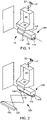
- FIG. 1 illustrates an automatic floor cleaning and recovery unit 100 in accordance with the present invention that is floor-mounted with a bracket 114 under a wall-mounted urinal 20 .
- the automatic floor cleaning and recovery unit 100 has a fixed unit 110 , a sensor 112 on the fixed unit 110 and a mobile unit 130 retracted into the fixed unit.
- the sensor is mounted with a line of view in the direction of the target area 10 of floor to be cleaned by the mobile unit 130 upon extension and retraction from the fixed unit 110 .
- FIG. 2 illustrates a perspective view of the automatic floor cleaning and recovery unit 100 of FIG. 1 with the mobile unit 130 extended by extension mechanism 120 .
- the extension mechanism 120 drops the mobile unit 130 so that scraping implement 132 comes in contact with the floor.
- the disinfectant solution tubing resides inside the extension mechanism.
- waste solution is recovered by the vacuum ports 134 .
- FIGS . 3-5 illustrate front, side, and top views of the automatic floor cleaning and recovery unit 100 of FIG. 1 .
- the overall shape of the fixed unit 110 is illustrated as generally rectangular in shape, but can be designed in a variety of shapes.
- the mobile unit 130 of the automatic floor and recovery unit 100 in this embodiment of the invention, is designed to reside inside the fixed unit when fully retracted. However, in other alternative non-limiting embodiments of the invention, the mobile unit 130 may reside adjacent to the fixed unit 110 .
- the automatic floor cleaning and recovery unit 100 is floor-mounted, in this non-limiting embodiment of the invention, using bracket 114 . Screws or bolts may be used to permanently mount the unit 100 to the floor, wall, or lavatory appliance. Alternatively, the unit 100 may be temporarily mounted to the floor or wall using suction cups or other temporary mounting hardware.
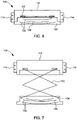
- FIGS. 6-8 illustrate the automatic floor cleaning and recovery unit 100 of FIG. 1 when the mobile unit 130 is in a retracted position ( FIG. 6 ) and in an extended position ( FIGS. 7-8 ).
- the mobile unit 130 has two scraping elements 132 and a band of disinfectant solution spray ports 136 between the two scraping elements 132 .
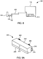
- FIG. 9A is an alternative non-limiting embodiment of the invention having a top opening lid 240 for access to the internal mechanisms of the fixed unit 210 of the cleaning and recovery unit 200 .
- the lid 240 is attached to the fixed unit 210 by a pair of hinges 260 .
- FIG. 9B illustrates the top opening lid 240 in an open position for access to the disinfectant solution tank 218 and recovery tank 216 .
- the lid 240 may optionally have a lock (not illustrated) to permit access to the internal mechanisms of the fixed unit 210 only by authorized personnel.
- FIG. 9C illustrates another alternative embodiment of the invention having separate top opening lids 240 for access to particular internal components of the cleaning and recovery unit 202 .
- each lid 240 has its own hinge 260 .
- Each lid 260 may have its own lock (not illustrated). Having lids with separate locks would provide for limited or no access to certain internal compartments of the cleaning and recovery unit. For example, as illustrated in FIG. 9D , during ordinary maintenance of the unit 202 access may be available to replace the disinfectant solution tank 218 and recovery tank 216 but not to replace an internal battery, for example, which would be accessible to the bearer of a separate key.
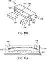
- FIGS. 10A-10B illustrate another alternative non-limiting embodiment of the invention whereby the fixed unit 310 of the cleaning and recovery unit 300 has ports 350 for front access to insert and remove internal components, such as the disinfectant solution tank 318 and recovery tank 316 .
- the disinfectant solution tank and recovery tank are shown with windows to see the level of solution within each tank.
- FIGS. 11A-11C illustrate bottom views of the mobile units 430, 530, and 630 in accordance with alternative non-limiting embodiments of the invention.
- two scraping elements 432 are provided in the bottom view of the alternative non-limiting embodiment of the mobile unit 430 in FIG. 11A . These scraping elements are preferably shaped in an arc to assist in the recovery of waste solution as the mobile unit 430 is retracted to the fixed unit. In between the two scraping elements 432 is a band of disinfectant solution spray ports 436 .
- the mobile unit 430 also has a brush 435 to assist in the removal of debris.
- scraping elements 532 are provided in the bottom view of the alternative non-limiting embodiment of the mobile unit 530 in FIG. 11B . Both scraping elements 532 are preferably shaped in an arc to assist in the recovery of waste solution as the mobile unit 530 is retracted to the fixed unit. In between the two scraping elements 532 are a band of disinfectant solution spray ports 536 and a brush 535 .
- both scraping elements 632 are provided. Both scraping elements 632 are preferably shaped in an arc to assist in the recovery of waste solution as the mobile unit 630 is retracted to the fixed unit. In between the two scraping elements 632 are a band of disinfectant solution spray ports 636 and a brush 635 .
- the mobile unit 630 has a band of vacuum ports 634 for suctioning waste solution. The suctioning of waste solution through vacuum ports 634 can occur during extension of the mobile unit 630 , during retraction of the mobile unit 630 , or during extension and retraction of the mobile unit 630 .
- These vacuum ports 634 on the mobile unit 630 can function in addition to or instead of the vacuum ports on the fixed unit.
- the vacuum ports 634 on the mobile unit 630 would be connected by tubing to the fixed unit.
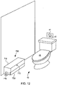
- an automatic floor cleaning and recovery unit 700 can be floor-mounted adjacent to a floor-mounted toilet 40 with a wall-mounted flush sensor 41 and manual flush 42 .
- the floor cleaning and recovery unit 700 can also be floor-mounted or wall-mount adjacent to a wall or floor-mounted sink as well as a wall or floor-mounted hand drying machine.
- the fixed unit 710 is permanently mounted to the floor with bracket 714 .
- the fixed unit 710 may also be temporarily wall or floor-mounted using suction cups or other temporary mounting hardware.
- FIG. 13 illustrates the floor cleaning and recovery unit of FIG. 12 in an extended position.
- FIG. 14 illustrates another non-limiting embodiment of the present invention.
- the automatic floor cleaning and recovery unit 800 is floor-mounted adjacent to a wall-mounted urinal 20 having a wall-mounted flush sensor 21 and manual flush 22 , wherein the disinfectant solution tank 816 is separately wall-mounted and connected by tubing to the fixed unit 810 .
- This design is particularly advantageous when the fixed unit 810 is connected to an external drain (not illustrated).
- FIG. 15 is an illustration of another alternative non-limiting embodiment of the present invention.
- a vacuum or recovery tank are not required.
- the automatic floor cleaner 900 is floor-mounted using bracket 914 so that the fixed unit 910 is adjacent to a floor-mounted urinal 30.
- the extension mechanism 920 extends the mobile unit 930 , as shown in an extended position in FIG. 17 , from the fixed unit 910 in a direction towards the floor-mounted urinal 30 drain basin.
- the fixed unit 910 does not require a vacuum or recovery tank because the waste solution is directed to the external drain.
- the mobile unit 930 is preferably modified to push instead of pull the waste solution.
- FIGS. 16A-16C illustrate alternative non-limiting embodiments of mobile units 1030 , 1130 , 1230 of the present invention, wherein the mobile units are design to push instead of pull the waste solution.
- FIG. 16A illustrates a bottom view of mobile unit 1030 having two scraping units 1032 , a brush 1035 , and a band of disinfectant solution spray ports 1036 . The arc of each scraping unit 1032 assists in the disposal of waste solution.
- FIG. 16B illustrates an alternative non-limiting embodiment of the invention wherein mobile unit 1130 has two scraping units 1132 and a band of disinfectant solution spray ports 1136 .
- FIG. 16C illustrates a bottom view of a mobile unit 1230 having tow scraping units 1232 and a band of disinfectant solution spray ports 1216 in between the scraping elements 1232 .
- FIG. 18 illustrates another alternative non-limiting embodiment of the invention.
- the mobile unit 1330 in FIG. 18 has two forward wheels 1370 and two rearward wheels 1380 .
- the forward wheels 1370 are distal to the fixed unit (not shown) and the rearward wheels 1380 are proximal to the fixed unit (not shown).
- Between the forward wheels 1370 and the rearward wheels 1380 are two scraping elements 1332 .
- Not shown in FIG. 18 are disinfectant solution ports and tubing, engagement with the extension mechanism, optional brush, and optional vacuum ports and tubing.
- mobile unit 1330 rolls on all four wheels during extension of the mobile unit 1330 from the fixed unit (not shown).
- the rearward wheels Upon activation of the linear actuator 1390 , the rearward wheels are lifted from contact with the floor and the scraping elements 1332 are pressed to the floor upon retraction of the mobile unit to the fixed unit.
- linear actuator 1390 is activated to raise the proximal portion of the mobile unit and to lower the distal portion of the mobile unit. In this way, the scraping elements 1332 do not come in contact with the floor upon extension of the mobile unit 1330 from the fixed unit but do contact the floor upon retraction of the mobile unit 1330 to the fixed unit.
- the forward wheels 1370 and the rearward wheels 1380 are connected by a frame 1333 .
- the frame 1333 is directly and fixedly connected to the forward wheels 1370 .
- the frame 1333 is pivotally connected to the rearward wheels by pins 1381 .
- the linear actuator 1390 is directly and fixedly connected to the forward wheels 1370 and is pivotally connected to the mobile unit by pivot pin 1382 .
- the pivot pin 1382 of the linear actuator 1390 may be in the same line of axis I formed between pins 1381 , but preferably is slightly elevated E above the line of axis I between the pins 1381 .
- the rearward wheels 1380 are elevated upward in the direction E .
- FIG. 19 illustrates another non-limiting embodiment of the present invention.
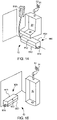
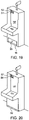
- the automatic floor cleaning and recovery unit is housed within wall-mounted urinal 50 .
- the cleaning and recovery unit uses its own sensor 53 to activate the extension of mobile unit 54 and wall-mounted urinal 50 uses its own integrated flush sensor 51 and manual flush 52 .
- FIG. 20 illustrates another non-limiting embodiment of the present invention.
- the automatic floor cleaning and recovery unit is integrated into wall-mounted urinal 55 .
- the cleaning and recovery unit in this embodiment utilizes the wall-mounted urinal's flush sensor 56 and manual flush 57 to activate the extension of mobile unit 59 .
- FIG. 21 illustrates another non-limiting embodiment of the present invention.
- the automatic floor cleaning and recovery unit is housed within a floor-mounted toilet 60 .
- the cleaning and recovery unit uses its own sensor 63 to activate the extension of mobile unit 64 and floor-mounted toilet 60 uses its own wall-mounted flush sensor 61 and manual flush 62 .
- FIG. 22 illustrates another non-limiting embodiment of the present invention.
- the automatic floor cleaning and recovery unit is integrated into floor-mounted toilet 65 .
- the cleaning and recovery unit in this embodiment utilizes the floor-mounted toilet's flush sensor 66 and manual flush 67 to activate the extension of mobile unit 69 .
- FIG. 23 illustrates another non-limiting embodiment of the present invention.
- the automatic floor cleaning and recovery unit is housed within a wall-mounted, paper-dispensing, hand drying device 70 .
- the cleaning and recovery unit uses its own sensor 73 to activate the extension of mobile unit 74 .
- the wall-mounted, paper-dispensing, hand drying device has no sensor associated with its paper dispenser 71 and trash container 72 .
- FIG. 24 illustrates another non-limiting embodiment of the present invention.
- the automatic floor cleaning and recovery unit is integrated into wall-mounted, paper-dispensing, hand drying device 75 .
- the mobile unit 79 in this embodiment, is activated by sensor 78, which is mounted on hand drying device 75 .
- the wall-mounted, paper-dispensing, hand drying device 75 has no sensor associated with its paper dispenser 76 and trash container 77 .
- FIG. 25 illustrates another non-limiting embodiment of the present invention.
- the automatic floor cleaning and recovery unit is housed within a wall-mounted, forced-air, hand drying device 80.
- the cleaning and recovery unit uses its own sensor 83 to activate the extension of mobile unit 84 independent of the wall-mounted, forced-air, hand drying device sensors 81 that are used for activation of forced air.
- FIG. 26 illustrates another non-limiting embodiment of the present invention.
- the automatic floor cleaning and recovery unit is integrated into wall-mounted, forced-air, hand drying device 85 .
- the mobile unit 88 in this embodiment, is activated on a synchronized basis with the hand drying device sensors 81 , such that the mobile unit 88 is extended at a predetermined period of time after the de-activation of the hand drying device sensors 81 to allow time for people to step away from the device 85.
- Wall-mounted, forced-air, hand drying device 85 also has a side panel 87 to access the internal components of the integrated automatic floor cleaning and recovery unit.
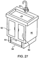
- FIG. 27 illustrates another non-limiting embodiment of the present invention.
- the automatic floor cleaning and recovery unit is housed within a floor-mounted sink cabinet 90 .
- the cleaning and recovery unit uses its own sensor 93 to activate the extension of mobile unit 94 independent of the faucet sensor 91 that is used to activate the flow of water.
- Floor-mounted sink cabinet 90 also has front panels 92 to access the internal components of the cleaning and recovery unit that is housed inside the sink cabinet 90 .
- a method of automatically cleaning a target area of a floor comprises the steps of (a) activating a sensor, (b) lifting and extending a mobile unit, (c) spraying disinfectant solution onto the target area of floor during extension of the mobile unit, (d) dropping the mobile unit so that the mobile unit comes into physical contact with the floor, and (e) retracting the mobile unit to recover waste solution.
- the retracting the mobile unit step (e) further comprises the steps of scraping and suctioning.
- a method of automatically cleaning a target area of a floor comprises the steps of (a) activating a sensor, (b) tilting and extending a mobile unit, (c) dropping the mobile unit so that the mobile unit comes into physical contact with the floor, (d) spraying disinfectant solution onto the target area of floor while retracting of the mobile unit, and (e) retracting the mobile unit to recover waste solution.
- the retracting the mobile unit step (e) further comprises the steps of scraping and suctioning.
- the method of automatically cleaning a target area of a floor comprises the steps of (a) activating a sensor, (b) extending and rotating a mobile unit, (c) spraying disinfectant solution onto the target area of floor during extension and rotation of the mobile unit, and (d) retracting the mobile unit.
Landscapes
- Health & Medical Sciences (AREA)
- Public Health (AREA)
- Epidemiology (AREA)
- Life Sciences & Earth Sciences (AREA)
- Engineering & Computer Science (AREA)
- Hydrology & Water Resources (AREA)
- Water Supply & Treatment (AREA)
- Sanitary Device For Flush Toilet (AREA)
- Apparatus For Disinfection Or Sterilisation (AREA)
- Toilet Supplies (AREA)
- Vehicle Cleaning, Maintenance, Repair, Refitting, And Outriggers (AREA)
Description
- This invention generally relates to automatic floor cleaning machines.
- Those who frequent public men's restrooms are all too familiar with unsanitary conditions that exist on the floor in front of and around urinals. Despite the best efforts of the cleaning workforce using traditional cleaning tools, pools of urine collect in front of and in the area on the floor around the urinal. Not desiring to step in a pool of urine, subsequent users are forced to stand further and further away from the urinal, which winds up contributing even further to the problem.
-
U.S. Patent Publication 2015/0033496 and relatedU.S. Patent No. 8,887,340 disclose a mobile floor cleaning apparatus with a chassis supported by a plurality of wheels with one steerable via a steering wheel interconnected to a housing, wherein the chassis has a plurality of movable housing members to operate in tight spaces. -
U.S. Patent No. 8,448,293 discloses a mobile wet extractor floor brush adapted for movement on a surface being cleaned having a base assembly for movement on the surface, an operating handle for controlling the movement of the wet extractor pivotally attached to the base assembly, a supply tank having an outlet, a recovery tank having an inlet and an outlet, and an agitator.U.S. Patent No. 6,370,453 discloses a self-moving service robot for automatic examination of floor surfaces and for suction of dust from floor surfaces that is programed to explore areas and detect potential obstacles using sensors. -
U.S. Patent No. 5,199,996 discloses a mobile apparatus for cleaning floors having a cleaning device placed on a first side of the apparatus to perform cleaning perpendicular to the general direction of advance of the apparatus. -
U.S. Patent No. 5,012,886 discloses a self-guided mobile unit and cleaning apparatus that follows guides such as walls or other obstacles, engages the guides with a detector element and controls the steering of the apparatus in response to the level of forces sensed by the detector. -
U.S. Patent No. 3,401,420 discloses a vacuum cleaner mounted to a maid's cart but rotatable around a vertical axis for winding of the vacuum hose and cord storage to facilitate cleaning while the vacuum cleaner remains on the maid's cart. -
JP6136809 -
U.S. Patent Publication 2013-0092190 discloses a robot cleaner that travels on a floor with an obstacle sensing unit and an auxiliary cleaning unit mounted to the bottom of the robot body, such that the auxiliary cleaning unit is extendable or retractable when an obstacle is sensed. -
U.S. Patent Publication 2013-0175802 discloses a powered apparatus for fluid applications having a housing dimensioned and configured for mounting in a fluid conduit. -
U.S. Patent No. 8,122,555 discloses a mobile floor cleaning apparatus capable of maximizing a user's convenience by an automatic operation, minimizing jolt or vibration and realizing enhanced endurance and safety with first and second movable members rectilinearly reciprocating along the same straight line in opposite directions with each other. - WIPO Publication
WO 2004-017805 discloses a mobile floor cleaning apparatus with at least one tool that impinges on the floor, at least one vapor outlet, and at least one cleaner outlet. -
U.S. Patent No. 5,628,086 discloses a mobile floor cleaning apparatus with four wheels, two of which are steerable by a steering wheel, to permit tight turns. - International Journal of Industrial Ergonomics 35 (2005) 247-266 discloses concerns of design and use of workplace cleaning equipment by cleaning workforce using demanding and labor intensive buffing machines, floor polishing machines, wet and dry vacuums, and other cleaning tools.
-
JP 2005213785 -
JP 2010099401 - The invention is defined by the claims.
- The present disclosure relates to an automatic floor cleaner and recovery unit comprising a cleaning and recovery unit wherein the cleaning and recovery unit comprises a fixed unit, a mobile unit, and an extension mechanism connected to the fixed unit and the mobile unit to permit the extension and retraction of the mobile unit from and to the fixed unit. The present disclosure further relates to an automatic floor cleaner and recovery unit, wherein the fixed unit comprises a controller, a sensor, a motor, a power source, a disinfectant solution tank, a vacuum, and a recovery tank; wherein the fixed unit is mounted to a floor or wall in proximity to a urinal, toilet, sink, or hand drying device; wherein the controller and the sensor control the activation of the motor for the extension or retraction of the mobile unit; wherein the power source is AC or DC; wherein the sensor is mounted on the exterior of the cleaning and recovery unit with a line of view in the direction of a target area of floor, and, alternatively, wherein the sensor is mounted on a urinal, toilet, sink, or hand drying device; wherein the disinfectant solution tank is connected by tubing to the mobile unit for spraying disinfectant solution onto a target area of floor upon extension of the mobile unit from the fixed unit; wherein the timing of spraying disinfectant solution is controlled by the controller; wherein the vacuum further comprises its own collection tank, fan, motor, and exhaust port; wherein the vacuum is connected by tubing to the mobile unit for recovery of urine and disinfectant solution from the target area of floor upon retraction of the mobile unit to the fixed unit; wherein timing of the vacuum is controlled by the controller; wherein the vacuum collection tank is connected by tubing to the recovery tank; wherein an intake port of the vacuum is connected by tubing to the fixed unit in proximity of the mobile unit for the recovery of urine and disinfectant solution from a target area of floor upon retraction of the mobile unit to the fixed unit; wherein the recovery tank is connected to an external drain or replaced by tubing connected directly to the external drain; wherein the fixed unit is integrated into a urinal, toilet, sink, or hand drying device; wherein the fixed unit is housed with a urinal, toilet, sink, or hand drying device; wherein the fixed unit is a cartridge insertable and removable from a cavity in the urinal, toilet, sink, or hand drying device; wherein the mobile unit further comprises a spray port for spraying disinfectant solution onto a target area of floor, a recovery port for suctioning solution from the target area, and a scraping implement for contacting the target area and collecting the solution from the target area upon retraction of the mobile unit to the fixed unit; wherein the mobile unit further comprises a brush; wherein the scraping implement is a squeegee; and wherein the extension mechanism first lifts and then extends the mobile unit and then the retraction mechanism first drops and retracts the mobile unit.
- The present disclosure relates to a method of automatically cleaning a floor surface using a cleaning and recovery unit comprising the steps of (a) activating a sensor, (b) extending a mobile unit, (c) spraying disinfectant solution onto a target area of floor during extension of the mobile unit, (d) contacting the mobile unit with the floor, and (e) retracting the mobile unit over the target area. The present disclosure further relates to a method of automatically cleaning a floor surface, wherein the step of retracting the mobile unit further comprises the steps of scraping and suctioning; wherein the step of activating a sensor is replaced by activation on a timed basis; and wherein the step of retracting is replaced by spraying disinfectant solution onto a target area of floor during retraction of the mobile unit.
- The present disclosure relates to an automatic floor cleaner comprising a cleaning unit, wherein the cleaning unit comprises a fixed unit, a mobile unit, and an extension mechanism connected to the fixed unit and the mobile unit to permit the extension and retraction of the mobile unit from and to the fixed unit; wherein the fixed unit comprises a controller, a sensor, a motor, a power source, and a disinfectant solution tank; wherein the disinfectant solution tank is connected by tubing to the mobile unit for spraying disinfectant solution onto a target area of floor upon extension of the mobile unit from the fixed unit.
- The present disclosure relates to a method of automatically cleaning a floor surface, comprising the steps of (a) activating the sensor, (b) extending the mobile unit, (c) spraying disinfectant solution onto the target area of floor during extension of the mobile unit, and (d) retracting the mobile unit. The present disclosure further relates to a method of automatically cleaning a floor surface, wherein the mobile unit is extended on a timed delay at predetermined time periods after the sensor is activated.
- For a better understanding of the present invention, reference is made to the following examples and drawings. Referring to the appended drawings:
-
FIG. 1 is a perspective view of a device according to a non-limiting embodiment of the present invention that is mounted to a floor under a wall-mounted urinal; -
FIG. 2 is a perspective view of the device ofFIG. 1 wherein the mobile unit is in an extended position; -
FIG. 3 is a front view of the device shown inFIG. 1 ; -
FIG. 4 is a side view of the device shown inFIG. 1 ; -
FIG. 5 is a top view of the device shown inFIG. 1 ; -
FIG. 6 is a bottom view of the device shown inFIG. 1 ; -
FIG. 7 is a bottom view of the device shown inFIG. 2 ; -
FIG. 8 is a side view of the device shown inFIG. 2 ; -
FIG. 9A is a perspective view of an embodiment of the present invention wherein the fixed unit is wall mounted and has a single top opening lid for access to the disinfectant solution tank and the recovery tank; -
FIG. 9B is a perspective view of the device shown inFIG. 9A showing the top opening lid in an open position; -
FIG. 9C is a perspective view of a device according to another non-limiting embodiment of the present invention wherein the fixed unit is floor-mounted and has separate top opening lids for access to particular internal components; -
FIG. 9D is a perspective view of the device shown inFIG. 9C showing two of the three top opening lids in open positions; -
FIG. 10A is a perspective view of a device according to another non-limiting embodiment of the present invention that is wall-mounted wherein the fixed unit has ports for front access to insert and remove internal components, specifically in this illustration the disinfectant solution tank and the recovery tank; -
FIG. 10B is a perspective view of the device shown inFIG. 10A showing the disinfectant solution tank and the recovery tank removed from the fixed unit; -
FIG. 11A to FIG. 11C are bottom views of the mobile unit according to other non-limiting embodiments of the present invention; -
FIG. 12 is a perspective view of a device according to another non-limiting embodiment of the present invention that is floor-mounted adjacent to a floor-mounted toilet; -
FIG. 13 is a perspective view of the device ofFIG. 12 wherein the mobile unit is in an extended position; -
FIG. 14 is a perspective view of a device according to another non-limiting embodiment of the present invention wherein the disinfectant solution tank is housed in a wall-mounted unit separate from the fixed unit but connected by tubing to the fixed unit; -
FIG. 15 is a perspective view of a device according to another embodiment of the present invention that is floor-mounted adjacent to a floor-mounted urinal and does not require a vacuum or recovery tank; -
FIG. 16A to FIG. 16C are bottom views of the mobile unit according to other non-limiting embodiments of the present invention; -
FIG. 17 is a perspective view of the device ofFIG. 15 wherein the mobile unit is in an extended position; -
FIG. 18 is a perspective view of a mobile unit according to another non-limiting embodiment of the present invention; -
FIG. 19 is a perspective view of a device according to another non-limiting embodiment of the present invention illustrating a fixed unit housed within a wall-mounted urinal; -
FIG. 20 is a perspective view of a device according to another non-limiting embodiment of the present invention illustrating a fixed unit integrated into a wall-mounted urinal; -
FIG. 21 is a perspective view of a device according to another non-limiting embodiment of the present invention illustrating a fixed unit housed within a floor-mounted toilet; -
FIG. 22 is a perspective view of a device according to another non-limiting embodiment of the present invention illustrating a fixed unit integrated into a floor-mounted toilet; -
FIG. 23 is a perspective view of a device according to another non-limiting embodiment of the present invention illustrating a fixed unit housed within a wall-mounted, paper-dispensing, hand drying device; -
FIG. 24 is a perspective view of a device according to another non-limiting embodiment of the present invention illustrating a fixed unit integrated into a wall-mounted, paper-dispensing, hand drying device; -
FIG. 25 is a perspective view of a device according to another non-limiting embodiment of the present invention illustrating a fixed unit housed within a wall-mounted, forced-air, hand drying device; -
FIG. 26 is a perspective view of a device according to another non-limiting embodiment of the present invention illustrating a fixed unit integrated into a wall-mounted, forced-air, hand drying device; and -
FIG. 27 is a perspective view of a device according to another non-limiting embodiment of the present invention illustrating a fixed unit housed within a floor-mounted sink. - Other features and aspects of the present invention will become more fully apparent from the following detailed description of some example embodiments, the appended claims, and the accompanying drawings.
- The inventor of the present application has recognized that there is a need for automatic floor cleaning machines, particularly in commercial, industrial, and institutional venues.
- An automatic floor cleaning and recovery unit in accordance with the present invention comprises a fixed unit, a mobile unit, an extension mechanism connected to the fixed unit and the mobile unit to permit the extension and retraction of the mobile unit from and to the fixed unit. In alternative non-limiting embodiments, the automatic floor cleaning and recovery unit may be wall-mounted or floor-mounted adjacent to a wall-mounted or floor-mounted urinal, adjacent to a wall-mounted or floor-mounted toilet, adjacent to a wall-mounted or floor-mounted sink, or adjacent to a wall-mounted or floor-mounted hand drying device. In further non-limiting alternative embodiments, the fixed unit is housed within a lavatory appliance, such as a urinal, toilet, sink, or hand drying device. In further non-limiting alternative embodiments, the fixed unit is a cartridge that is insertable and removable from a cavity in the urinal, toilet, sink, or hand drying device. In further, non-limiting alternative embodiments, the fixed unit is integrated into a urinal, toilet, sink, or hand drying device.
- The fixed unit comprises a controller, a sensor, a motor, a power source, a disinfectant solution tank, a vacuum, and a recovery tank. Preferably, the fixed unit is positioned in proximity to a target area of a floor or surface for cleaning.
- The controller and the sensor control the activation of the motor for the extension and retraction of the mobile unit. The sensor is preferably mounted on the exterior of the cleaning and recovery unit with a line of view in the direction of a target area of floor or surface to be cleaned. Alternatively, the sensor may be mounted adjacent to the fixed unit or adjacent to the lavatory appliance. The sensor optionally is mounted on the adjacent urinal, toilet, sink, or hand drying device. In other alternative embodiments, the controller of the fixed unit uses the sensor of the adjacent lavatory appliance. The cleaning and recovery unit may also be designed to synchronize with the sensor of the adjacent lavatory appliance.
- The power source can be either AC or DC. The cleaning and recovery unit can be plugged into standard electrical outlets or wired directly to an electrical source. For areas that do not have electrical outlets or do not have electrical outlets in a convenient location, the cleaning and recovery unit can be powered by a battery. The battery source may be rechargeable or disposable. The cleaning and recovery unit can also be powered by the urinal, toilet, sink, or hand drying device, either when wall or floor-mounted or when housed within or integrated into the urinal, toilet, sink, or hand drying device.
- The disinfectant solution tank is housed in the fixed unit and is connected by tubing to the mobile unit for spraying disinfectant solution onto the target area of floor upon extension of the mobile unit from the fixed unit. In alternative non-limiting embodiments of the present invention, the disinfectant solution tank is not housed inside the fixed unit but is wall-mounted next to and connected to the fixed unit by way of tubing. This would provide additional space in the fixed unit for a larger recovery tank, allow additional space for a larger disinfectant solution tank, and decrease the possibility of any confusion during maintenance of the disinfectant solution tank and the recovery tank. The timing of spraying disinfectant solution is controlled by the controller. The disinfectant solution tank may have a port for external filling of additional disinfectant solution. In an alternative non-limiting embodiment, the disinfectant solution tank is a detachable cartridge or bag that can be replaced as needed. Optionally, a window or other indicator is provided on the exterior of the disinfectant solution tank and the fixed unit so that the level of disinfectant solution is visible or otherwise indicated.
- The disinfectant solution tank preferably contains a liquid cleaner for household, commercial, industrial, and institutional use, and, optionally, has anti-bacterial, anti-microbial and/or anti-viral properties. It is also preferable that the liquid cleaner be quick drying.
- Upon retraction of the mobile unit to the fixed unit, a vacuum recovers any waste solution and/or debris. The vacuum in the fixed unit has its own collection tank, fan, motor, and exhaust port. In a non-limiting alternative embodiment, the vacuum is connected by tubing to the mobile unit for the recovery of waste solution and/or debris from the target area during retraction of the mobile unit to the fixed unit. The timing of the vacuum is controlled by the controller. The vacuum collection tank is connected by tubing to the recovery tank or an external drain.
- The recovery tank is designed to receive the waste solution and/or debris collected by the vacuum. The recovery tank can be removable from the fixed unit for emptying and replacement into the fixed unit. In an alternative non-limiting embodiment, the recovery tank is removable for disposable and replaced with a new recovery tank. In another alternative non-limiting embodiment, the recovery tank is disposable and contains absorbent material/particles. In another alternative non-limiting embodiment, the recovery tank is external to the fixed unit and connected by tubing to the fixed unit. In another alternative non-limiting embodiment, the recovery tank is connected to an external drain or replaced by tubing directly to the external drain. Optionally, a window or other indicator is provided on the exterior of the fixed unit and the recovery tank so that the level of waste solution is visible or otherwise indicated.
- In alternative non-limiting embodiments of the present invention, the fixed unit has one or more top opening lids for access to all or some of the internal components, such as the disinfectant solution tank, the recovery tank, and/or optional battery. In other non-limiting embodiments of the present invention, the fixed unit has front access ports for access to all or some of the internal components, such as the disinfectant solution tank, the recovery tank, and/or optional battery. In other non-limiting embodiments of the present invention, the internal components of the cleaning and recovery unit are accessed by a panel on the urinal, toilet, sink, or hand drying device.
- The mobile unit comprises spray port(s) for spraying disinfectant solution onto the target area and a scraping implement, like one or more squeegee, for contacting the target area of floor and collecting the waste solution and/or debris from the target area upon retraction of the mobile unit to the fixed unit. In other non-limiting embodiments of the invention, the mobile unit also contains recovery vacuum port(s) for suctioning waste solution and/or debris from the target area during retraction of the mobile unit to the fixed unit. In other non-limiting embodiments of the invention, the mobile unit also contains a brush wherein the brush is either fixed or moves by rotating or spinning. In other non-limiting embodiments of the invention, the mobile unit sprays disinfectant solution onto the target area upon extension of the mobile unit from the fixed unit. In other non-limiting embodiments of the invention, the scraping implement contacts the target area of the floor upon extension of the mobile unit thereby pushing the waste solution and/or debris from the target area to a floor drain or floor-mounted urinal drain basin.
- The vacuum ports may be located on the bottom of the mobile unit at positions proximal to the fixed unit and distal to the scraping implement, and/or distal to the fixed unit and proximal to the scraping implement depending on the design.
- The disinfectant solution spray ports may be located on the bottom of the mobile unit at positions distal to the fixed unit and proximal to the scraping implement, and/or proximal to the fixed unit and distal to the scraping implement depending on the design.
- The scraping implement preferably has two arcs of squeegee to enhance the capture capability of the mobile unit. The arcs may be convex or concave depending on the design.
- The extension mechanism is powered by the motor housed in the fixed unit. According to a non-limiting embodiment of the invention, upon activation by the controller, the extension mechanism first lifts and then extends the mobile unit. Upon initiation of the extension of the mobile unit, the controller then activates the spraying of disinfectant solution over the target area. The extension mechanism supports, either internally or externally, the disinfectant solution tubing that connects the disinfectant solution tank to the mobile unit disinfectant port(s). In alternative non-limiting embodiments of the invention, the extension mechanism also supports, either internally or externally, the vacuum tubing that connects the vacuum collection tank to the recovery port(s) on the mobile unit. Upon retraction of the mobile unit, the extension mechanism first drops and then retracts the mobile unit.
- In another alternative non-limiting embodiment of the invention, the mobile unit is extended from the fixed unit by the extension mechanism in a raised position and when fully extended the extension mechanism drops the mobile unit into a lowered position to contact the surface of the floor. The scraping elements of the mobile unit are in contact with the floor as the mobile unit is retracted back to the fixed unit.
- In another alternative non-limiting embodiment of the invention, the mobile unit has one or more wheels that support the mobile unit and roll on the floor during the extension and retraction of the mobile unit. In alternative non-limiting embodiments of the invention, the mobile unit has at least two wheels. In further alternative non-limiting embodiments of the invention, the mobile unit has two forward wheels distal to the fixed unit and two rearward wheels proximal to the fixed unit. In further alternative non-limiting embodiments of the invention, the forward wheels are raised on extension of the mobile unit, which pivots the mobile unit upward so that it does not contact the floor on extension, and lowered on retraction of the mobile unit, which pivots the mobile unit downward to come in contact with the floor on retraction. In other alternative non-limiting embodiments of the invention, the forward wheels and rearward wheels are in contact with the floor on extension of the mobile unit. Then the rearward wheels are raised to bring the scraping elements of the mobile unit in contact with the floor on retraction. In other alternative non-limiting embodiments of the invention, the forward wheels are raised on extension of the mobile unit and the rearward wheels are raised on retraction of the mobile unit in order to keep the scraping elements above the surface of the floor on extension of the mobile unit and to bring the scraping elements in contact with the surface of the floor on retraction of the mobile unit.
- In another example embodiment of the present invention, an automatic floor cleaning unit in accordance with the present invention is mounted to the floor adjacent to a traditional floor-mounted urinal. The cleaning unit comprises a fixed unit, a mobile unit, and an extension mechanism connected to the fixed unit and the mobile unit to permit the extension and retraction of the mobile unit from and to the fixed unit. The fixed unit comprises a controller, a sensor, a motor, a power source, and a disinfectant solution tank. In this example embodiment of the present invention, the cleaning unit does not contain a vacuum or recovery tank because it takes advantage of the floor-mounted urinal for disposal of waste solution and/or debris.
- The extension mechanism has an angle arm that both extends and rotates the mobile unit relative to the fixed unit in order to clean a path in the direction of the floor-mounted urinal drain basin.
- In another alternative non-limiting embodiment of the invention, the fixed unit is not mounted to a floor or wall but is integrated into the design of a urinal, toilet, sink, or hand drying unit. In another alternative non-limiting embodiment of the invention, the fixed unit is housed within the urinal, toilet, sink, or hand drying unit.
- In another alternative non-limiting embodiment of the invention, the disinfectant solution tank is not housed inside the fixed unit but is wall-mounted next to and connected to the fixed unit, for example, by tubing.
- In another alternative non-limiting embodiment of the invention, the automatic floor cleaning and recovery unit is permanently or temporarily mounted adjacent to a urinal, toilet, sink, or hand drying unit so that the entire unit can be removed, discarded, and/or replaced.
- In alternative non-limiting embodiments of the invention, the external design of the fixed unit may be stylized to match the decor of the restroom in color, size and overall shape.
- In a non-limiting alternative embodiment of the invention, the controller and sensor may be set to extend the mobile unit each time the sensor is triggered. In other alternative non-limiting embodiments of the invention, the mobile unit is extended on an intermittent basis. For example, the mobile unit would extend after every other time the sensor is triggered. In other alternative non-limiting embodiments of the invention, the mobile unit is extended only when the sensor is triggered during certain predetermined time periods. For example, the controller may be set to permit the extension of the mobile unit at 10 minute intervals for windows of 5 minutes during which time the mobile unit would be extended if the sensor is triggered at any predetermined frequency (such as every time, or every other time). During the 10 minute interval, the mobile unit would not extend despite the triggering of the sensor. In other alternative non-limiting embodiments of the invention, the mobile unit is extended after a period of delay so that the mobile unit would extend only after a certain number of minutes of non-use after the sensor is last triggered. In other alternative non-limiting embodiments of the invention, the mobile unit is extended at predetermined times (such as every two hours, or at particular times) without the need for triggering any sensor. It may be preferable in restrooms with low usage to activate the device on a daily basis, for example, despite the non-usage of a particular urinal. Further, in high usage locations, like stadium restrooms, it may be preferable to activate the device on a delay, instead of after each user, between the high usage time periods.
- Referring to the Figures,
FIG. 1 illustrates an automatic floor cleaning andrecovery unit 100 in accordance with the present invention that is floor-mounted with abracket 114 under a wall-mountedurinal 20. The automatic floor cleaning andrecovery unit 100 has a fixedunit 110, asensor 112 on the fixedunit 110 and amobile unit 130 retracted into the fixed unit. The sensor is mounted with a line of view in the direction of thetarget area 10 of floor to be cleaned by themobile unit 130 upon extension and retraction from the fixedunit 110. -
FIG. 2 illustrates a perspective view of the automatic floor cleaning andrecovery unit 100 ofFIG. 1 with themobile unit 130 extended byextension mechanism 120. On retraction, theextension mechanism 120 drops themobile unit 130 so that scraping implement 132 comes in contact with the floor. In this embodiment of the invention, the disinfectant solution tubing resides inside the extension mechanism. Upon retraction of themobile unit 130, waste solution is recovered by thevacuum ports 134. -
FIGS. 3-5 illustrate front, side, and top views of the automatic floor cleaning andrecovery unit 100 ofFIG. 1 . The overall shape of the fixedunit 110 is illustrated as generally rectangular in shape, but can be designed in a variety of shapes. Themobile unit 130 of the automatic floor andrecovery unit 100, in this embodiment of the invention, is designed to reside inside the fixed unit when fully retracted. However, in other alternative non-limiting embodiments of the invention, themobile unit 130 may reside adjacent to the fixedunit 110. The automatic floor cleaning andrecovery unit 100 is floor-mounted, in this non-limiting embodiment of the invention, usingbracket 114. Screws or bolts may be used to permanently mount theunit 100 to the floor, wall, or lavatory appliance. Alternatively, theunit 100 may be temporarily mounted to the floor or wall using suction cups or other temporary mounting hardware. -
FIGS. 6-8 illustrate the automatic floor cleaning andrecovery unit 100 ofFIG. 1 when themobile unit 130 is in a retracted position (FIG. 6 ) and in an extended position (FIGS. 7-8 ). In this embodiment of the invention, themobile unit 130 has two scrapingelements 132 and a band of disinfectantsolution spray ports 136 between the two scrapingelements 132. -
FIG. 9A is an alternative non-limiting embodiment of the invention having atop opening lid 240 for access to the internal mechanisms of the fixedunit 210 of the cleaning andrecovery unit 200. In this embodiment, thelid 240 is attached to the fixedunit 210 by a pair ofhinges 260.FIG. 9B illustrates thetop opening lid 240 in an open position for access to thedisinfectant solution tank 218 andrecovery tank 216. Thelid 240 may optionally have a lock (not illustrated) to permit access to the internal mechanisms of the fixedunit 210 only by authorized personnel.FIG. 9C illustrates another alternative embodiment of the invention having separatetop opening lids 240 for access to particular internal components of the cleaning andrecovery unit 202. In this embodiment, eachlid 240 has itsown hinge 260. Eachlid 260 may have its own lock (not illustrated). Having lids with separate locks would provide for limited or no access to certain internal compartments of the cleaning and recovery unit. For example, as illustrated inFIG. 9D , during ordinary maintenance of theunit 202 access may be available to replace thedisinfectant solution tank 218 andrecovery tank 216 but not to replace an internal battery, for example, which would be accessible to the bearer of a separate key. -
FIGS. 10A-10B illustrate another alternative non-limiting embodiment of the invention whereby the fixedunit 310 of the cleaning andrecovery unit 300 hasports 350 for front access to insert and remove internal components, such as thedisinfectant solution tank 318 andrecovery tank 316. The disinfectant solution tank and recovery tank are shown with windows to see the level of solution within each tank. -
FIGS. 11A-11C illustrate bottom views of themobile units mobile unit 430 inFIG. 11A , two scrapingelements 432 are provided. These scraping elements are preferably shaped in an arc to assist in the recovery of waste solution as themobile unit 430 is retracted to the fixed unit. In between the two scrapingelements 432 is a band of disinfectantsolution spray ports 436. In addition, in this non-limiting embodiment of the invention, themobile unit 430 also has abrush 435 to assist in the removal of debris. - In the bottom view of the alternative non-limiting embodiment of the
mobile unit 530 inFIG. 11B , two scrapingelements 532 are provided. Both scrapingelements 532 are preferably shaped in an arc to assist in the recovery of waste solution as themobile unit 530 is retracted to the fixed unit. In between the two scrapingelements 532 are a band of disinfectantsolution spray ports 536 and abrush 535. - In the bottom view of the alternative non-limiting embodiment of the
mobile unit 630 inFIG. 11C , two scrapingelements 632 are provided. Both scrapingelements 632 are preferably shaped in an arc to assist in the recovery of waste solution as themobile unit 630 is retracted to the fixed unit. In between the two scrapingelements 632 are a band of disinfectantsolution spray ports 636 and abrush 635. In addition, themobile unit 630 has a band ofvacuum ports 634 for suctioning waste solution. The suctioning of waste solution throughvacuum ports 634 can occur during extension of themobile unit 630, during retraction of themobile unit 630, or during extension and retraction of themobile unit 630. Thesevacuum ports 634 on themobile unit 630 can function in addition to or instead of the vacuum ports on the fixed unit. Thevacuum ports 634 on themobile unit 630 would be connected by tubing to the fixed unit. - As illustrated in
FIG. 12 , an automatic floor cleaning andrecovery unit 700 can be floor-mounted adjacent to a floor-mountedtoilet 40 with a wall-mountedflush sensor 41 andmanual flush 42. The floor cleaning andrecovery unit 700 can also be floor-mounted or wall-mount adjacent to a wall or floor-mounted sink as well as a wall or floor-mounted hand drying machine. InFIG. 12 , the fixedunit 710 is permanently mounted to the floor withbracket 714. The fixedunit 710 may also be temporarily wall or floor-mounted using suction cups or other temporary mounting hardware.FIG. 13 illustrates the floor cleaning and recovery unit ofFIG. 12 in an extended position. -
FIG. 14 illustrates another non-limiting embodiment of the present invention. The automatic floor cleaning andrecovery unit 800 is floor-mounted adjacent to a wall-mountedurinal 20 having a wall-mountedflush sensor 21 andmanual flush 22, wherein thedisinfectant solution tank 816 is separately wall-mounted and connected by tubing to the fixedunit 810. This design is particularly advantageous when the fixedunit 810 is connected to an external drain (not illustrated). -
FIG. 15 is an illustration of another alternative non-limiting embodiment of the present invention. In some arrangements a vacuum or recovery tank are not required. Theautomatic floor cleaner 900 is floor-mounted usingbracket 914 so that the fixedunit 910 is adjacent to a floor-mountedurinal 30. Theextension mechanism 920 extends themobile unit 930, as shown in an extended position inFIG. 17 , from the fixedunit 910 in a direction towards the floor-mountedurinal 30 drain basin. In this embodiment, the fixedunit 910 does not require a vacuum or recovery tank because the waste solution is directed to the external drain. In this design, themobile unit 930 is preferably modified to push instead of pull the waste solution. -
FIGS. 16A-16C illustrate alternative non-limiting embodiments ofmobile units FIG. 16A illustrates a bottom view ofmobile unit 1030 having two scrapingunits 1032, abrush 1035, and a band of disinfectantsolution spray ports 1036. The arc of eachscraping unit 1032 assists in the disposal of waste solution.FIG. 16B illustrates an alternative non-limiting embodiment of the invention whereinmobile unit 1130 has twoscraping units 1132 and a band of disinfectantsolution spray ports 1136.FIG. 16C illustrates a bottom view of amobile unit 1230 havingtow scraping units 1232 and a band of disinfectantsolution spray ports 1216 in between the scrapingelements 1232. -
FIG. 18 illustrates another alternative non-limiting embodiment of the invention. Themobile unit 1330 inFIG. 18 has twoforward wheels 1370 and tworearward wheels 1380. Theforward wheels 1370 are distal to the fixed unit (not shown) and therearward wheels 1380 are proximal to the fixed unit (not shown). Between theforward wheels 1370 and therearward wheels 1380 are two scrapingelements 1332. Not shown inFIG. 18 are disinfectant solution ports and tubing, engagement with the extension mechanism, optional brush, and optional vacuum ports and tubing. In this alternative embodiment,mobile unit 1330 rolls on all four wheels during extension of themobile unit 1330 from the fixed unit (not shown). Upon activation of thelinear actuator 1390, the rearward wheels are lifted from contact with the floor and thescraping elements 1332 are pressed to the floor upon retraction of the mobile unit to the fixed unit. When themobile unit 1330 is fully extended, thenlinear actuator 1390 is activated to raise the proximal portion of the mobile unit and to lower the distal portion of the mobile unit. In this way, thescraping elements 1332 do not come in contact with the floor upon extension of themobile unit 1330 from the fixed unit but do contact the floor upon retraction of themobile unit 1330 to the fixed unit. In this embodiment, theforward wheels 1370 and therearward wheels 1380 are connected by aframe 1333. Theframe 1333 is directly and fixedly connected to theforward wheels 1370. Theframe 1333 is pivotally connected to the rearward wheels bypins 1381. Thelinear actuator 1390 is directly and fixedly connected to theforward wheels 1370 and is pivotally connected to the mobile unit bypivot pin 1382. Thepivot pin 1382 of thelinear actuator 1390 may be in the same line of axis I formed betweenpins 1381, but preferably is slightly elevated E above the line of axis I between thepins 1381. Upon actuation oflinear actuator 1390, therearward wheels 1380 are elevated upward in the direction E . -
FIG. 19 illustrates another non-limiting embodiment of the present invention. The automatic floor cleaning and recovery unit is housed within wall-mountedurinal 50. In this embodiment, the cleaning and recovery unit uses itsown sensor 53 to activate the extension ofmobile unit 54 and wall-mountedurinal 50 uses its own integratedflush sensor 51 andmanual flush 52. -
FIG. 20 illustrates another non-limiting embodiment of the present invention. In this embodiment, the automatic floor cleaning and recovery unit is integrated into wall-mountedurinal 55. The cleaning and recovery unit in this embodiment utilizes the wall-mounted urinal's flush sensor 56 andmanual flush 57 to activate the extension ofmobile unit 59. -
FIG. 21 illustrates another non-limiting embodiment of the present invention. The automatic floor cleaning and recovery unit is housed within a floor-mountedtoilet 60. In this embodiment, the cleaning and recovery unit uses itsown sensor 63 to activate the extension ofmobile unit 64 and floor-mountedtoilet 60 uses its own wall-mountedflush sensor 61 andmanual flush 62. -
FIG. 22 illustrates another non-limiting embodiment of the present invention. In this embodiment, the automatic floor cleaning and recovery unit is integrated into floor-mountedtoilet 65. The cleaning and recovery unit in this embodiment utilizes the floor-mounted toilet'sflush sensor 66 andmanual flush 67 to activate the extension ofmobile unit 69. -
FIG. 23 illustrates another non-limiting embodiment of the present invention. The automatic floor cleaning and recovery unit is housed within a wall-mounted, paper-dispensing,hand drying device 70. In this embodiment, the cleaning and recovery unit uses itsown sensor 73 to activate the extension ofmobile unit 74. The wall-mounted, paper-dispensing, hand drying device has no sensor associated with itspaper dispenser 71 andtrash container 72. -
FIG. 24 illustrates another non-limiting embodiment of the present invention. In this embodiment, the automatic floor cleaning and recovery unit is integrated into wall-mounted, paper-dispensing,hand drying device 75. Themobile unit 79, in this embodiment, is activated bysensor 78, which is mounted onhand drying device 75. The wall-mounted, paper-dispensing,hand drying device 75 has no sensor associated with itspaper dispenser 76 andtrash container 77. -
FIG. 25 illustrates another non-limiting embodiment of the present invention. The automatic floor cleaning and recovery unit is housed within a wall-mounted, forced-air,hand drying device 80. In this embodiment, the cleaning and recovery unit uses itsown sensor 83 to activate the extension ofmobile unit 84 independent of the wall-mounted, forced-air, handdrying device sensors 81 that are used for activation of forced air. -
FIG. 26 illustrates another non-limiting embodiment of the present invention. In this embodiment, the automatic floor cleaning and recovery unit is integrated into wall-mounted, forced-air,hand drying device 85. Themobile unit 88, in this embodiment, is activated on a synchronized basis with the handdrying device sensors 81, such that themobile unit 88 is extended at a predetermined period of time after the de-activation of the handdrying device sensors 81 to allow time for people to step away from thedevice 85. Wall-mounted, forced-air,hand drying device 85 also has aside panel 87 to access the internal components of the integrated automatic floor cleaning and recovery unit. -
FIG. 27 illustrates another non-limiting embodiment of the present invention. The automatic floor cleaning and recovery unit is housed within a floor-mountedsink cabinet 90. In this embodiment, the cleaning and recovery unit uses itsown sensor 93 to activate the extension ofmobile unit 94 independent of thefaucet sensor 91 that is used to activate the flow of water. Floor-mountedsink cabinet 90 also hasfront panels 92 to access the internal components of the cleaning and recovery unit that is housed inside thesink cabinet 90. - According to a non-limiting embodiment of the present invention, a method of automatically cleaning a target area of a floor comprises the steps of (a) activating a sensor, (b) lifting and extending a mobile unit, (c) spraying disinfectant solution onto the target area of floor during extension of the mobile unit, (d) dropping the mobile unit so that the mobile unit comes into physical contact with the floor, and (e) retracting the mobile unit to recover waste solution. In a non-limiting embodiment of the invention, the retracting the mobile unit step (e) further comprises the steps of scraping and suctioning.
- According to another non-limiting embodiment of the present invention, a method of automatically cleaning a target area of a floor comprises the steps of (a) activating a sensor, (b) tilting and extending a mobile unit, (c) dropping the mobile unit so that the mobile unit comes into physical contact with the floor, (d) spraying disinfectant solution onto the target area of floor while retracting of the mobile unit, and (e) retracting the mobile unit to recover waste solution. In a non-limiting embodiment of the invention, the retracting the mobile unit step (e) further comprises the steps of scraping and suctioning.
- According to another non-limiting embodiment of the present invention, the method of automatically cleaning a target area of a floor comprises the steps of (a) activating a sensor, (b) extending and rotating a mobile unit, (c) spraying disinfectant solution onto the target area of floor during extension and rotation of the mobile unit, and (d) retracting the mobile unit.
- The invention is not restricted to the embodiments described, but, on the contrary, covers any modification on form and any alternative form of embodiment that falls within the scope of the present invention, as defined in the appended claims. While there have been described what are believed to be preferred embodiments of the invention, those skilled in the art will recognize that other and further modifications may be made thereto, without departing from the scope of the present invention, as defined by the following claims.
Claims (13)
- An automatic floor cleaner (100, 700, 800, 900) comprising a cleaning and recovery unit, the cleaning and recovery unit comprises a fixable unit (110, 210, 310, 710, 810, 910), a mobile unit (54, 59, 64, 69, 74, 79, 84, 88, 94, 130, 430, 530, 630, 930, 1030, 1130, 1230, 1330), and an extension mechanism (120, 720, 920) connected to the fixable unit and the mobile unit to permit the extension and retraction of the mobile unit from and to the fixable unit, and wherein the fixable unit comprises a controller, a sensor (53, 56, 63, 66, 73, 78, 81, 83, 93, 112), a motor, a power source, and a vacuum; characterized in that the cleaning and recovery unit comprises a bracket (114) to permanently mount the unit to a floor, wall, or lavatory appliance, or suction cups or other temporary mounting hardware to temporarily mount the unit to a floor or wall in proximity to a urinal (20, 30, 50, 55), toilet (40, 60, 65), sink or hand drying device (70, 75, 80, 85), and in that the fixable unit further comprises a disinfectant solution tank (218, 318, 816) and a recovery tank (216, 316).
- The automatic floor cleaner (100, 700, 900) of claim 1, wherein the disinfectant solution tank (218, 318) is a detachable and replaceable cartridge.
- The automatic floor cleaner (100, 700, 800, 900) of claim 1 wherein the recovery tank (216, 316) is removable from the fixable unit (110, 210, 310, 710, 810, 910) for emptying and replacement into the fixable unit.
- The automatic floor cleaner (100, 700, 800, 900) of claim 1, wherein:the controller and the sensor (53, 56, 63, 66, 73, 78, 81, 83, 93, 112) control the activation of the motor for the extension or retraction of the mobile unit (54, 59, 64, 69, 74, 79, 84, 88, 94, 130, 430, 530, 630, 930, 1030, 1130, 1230, 1330);the power source is AC or DC;the sensor is mounted on the exterior of the cleaning and recoveryunit with a line of view in the direction of a target area (10) of floor; and/orthe sensor (56, 66, 78, 81) is mounted on a urinal (20, 30, 50, 55), toilet (40, 60, 65), sink, or hand drying device (70, 75, 80, 85).
- The automatic floor cleaner (100, 700, 800, 900) of claim 1, wherein the disinfectant solution tank (218) is connected by tubing to the mobile unit (54, 59, 64, 69, 74, 79, 84, 88, 94, 130, 430, 530, 630, 930, 1030, 1130, 1230, 1330) for spraying disinfectant solution onto a target area of floor upon extension of the mobile unit from the fixable unit (110, 210, 310, 710, 810, 910).
- The automatic floor cleaner (100, 700, 800, 900) of claim 5, wherein the timing of spraying disinfectant solution is controlled by the controller.
- The automatic floor cleaner (100, 700, 800, 900) of claim 1, wherein the vacuum further comprises its own collection tank, fan, motor, and exhaust port.
- The automatic floor cleaner (100, 700, 800, 900) of claim 7, wherein:the vacuum is connected by tubing to the mobile unit (54, 59, 64, 69, 74, 79, 84, 88, 94, 130, 430, 530, 630, 1030, 1130, 1230, 1330) for recovery of urine and disinfectant solution from the target area of floor upon retraction of the mobile unit to the fixable unit (110, 210, 310, 710, 810, 910);timing of the vacuum is controlled by the controller;the vacuum collection tank is connected by tubing to the recovery tank (216, 316); and/orthe vacuum collection tank is connected by tubing to the recovery tank and an intake port of the vacuum is connected by tubing to the fixable unit in proximity of the mobile unit (54, 59, 64, 69, 74, 79, 84, 88, 94, 130, 430, 530, 630, 1030, 1130, 1230, 1330) for the recovery of urine and disinfectant solution from a target area of floor upon retraction of the mobile unit to the fixable unit.
- The automatic floor cleaner (100, 700, 800, 900) of any preceding claim, wherein:the fixable unit is integrated into a urinal (20, 30, 50, 55), toilet (40, 60, 65), sink, or hand drying device (70, 75, 80, 85);the fixable unit is housed within a urinal, toilet, sink, or hand drying device;the fixable unit is housed within a urinal, toilet, sink, or hand drying device and the fixed unit is a cartridge insertable into and removable from a cavity in the urinal, toilet, sink, or hand drying device;the mobile unit (54, 59, 64, 69, 74, 79, 84, 88, 94, 130, 430, 530, 630, 930, 1030, 1130, 1230, 1330) further comprises a spray port (136, 436, 536, 636, 1036, 1136, 1216) for spraying disinfectant solution onto a target area of floor, a recovery port for suctioning solution from the target area, and a scraping implement (132, 432, 532, 632, 1032, 1132, 1232, 1332) for contacting the target area and collecting solution from the target area upon retraction of the mobile unit to the fixed unit;the mobile unit further comprises a brush (435, 535, 635, 1035);the mobile unit further comprises a spray port for spraying disinfectant solution onto a target area of floor, a recovery port for suctioning solution from the target area, and a scraping implement for contacting the target area and collecting solution from the target area upon retraction of the mobile unit to the fixable unit and the scrapping implement is a squeegee; and/orthe extension mechanism (120, 720, 920) first lifts and then extends the mobile unit, and wherein the retraction mechanism first drops and then retracts the mobile unit.
- The automatic floor cleaner (800) of claim 1, wherein the automatic floor cleaner further comprises a disinfectant solution tank (816) not housed inside the fixable unit (810) but wall-mounted next to and connected to the fixable unit (810) by way of tubing, and further wherein the disinfectant solution tank is connected by tubing to the mobile unit for spraying disinfectant solution onto a target area of floor upon extension of the mobile unit from the fixed unit.
- The automatic floor cleaner (800) of claim 1, wherein: the disinfectant solution tank (816) is not housed inside the fixable unit (810) and is wall-mounted next to the fixable unit and connected to the fixable unit (810) by tubing; and/or the recovery tank is external of the fixable unit (810) and connected to the fixable unit (810) by tubing.
- A method of automatically cleaning a floor surface using the cleaning and recovery unit of claim 1, comprising the steps of (a) activating the sensor, (b) extending the mobile unit, (c) spraying disinfectant solution onto the target area of floor during extension of the mobile unit, and (d) retracting the mobile unit.
- The method of claim 12, wherein the mobile unit is extended on a timed delay at predetermined time periods after the sensor is activated.
Applications Claiming Priority (2)
| Application Number | Priority Date | Filing Date | Title |
|---|---|---|---|
| US15/209,719 US10006192B2 (en) | 2016-07-13 | 2016-07-13 | Automatic floor cleaning machine and process |
| PCT/US2017/041595 WO2018013608A1 (en) | 2016-07-13 | 2017-07-11 | Automatic floor cleaning machine and process |
Publications (3)
| Publication Number | Publication Date |
|---|---|
| EP3485102A1 EP3485102A1 (en) | 2019-05-22 |
| EP3485102A4 EP3485102A4 (en) | 2020-01-01 |
| EP3485102B1 true EP3485102B1 (en) | 2022-12-07 |
Family
ID=60941680
Family Applications (1)
| Application Number | Title | Priority Date | Filing Date |
|---|---|---|---|
| EP17828335.4A Active EP3485102B1 (en) | 2016-07-13 | 2017-07-11 | Automatic floor cleaning machine and process |
Country Status (9)
| Country | Link |
|---|---|
| US (2) | US10006192B2 (en) |
| EP (1) | EP3485102B1 (en) |
| JP (1) | JP7096552B2 (en) |
| CN (1) | CN109689984A (en) |
| AU (1) | AU2017297370B2 (en) |
| CA (1) | CA3030286A1 (en) |
| ES (1) | ES2939843T3 (en) |
| MX (1) | MX2019000412A (en) |
| WO (1) | WO2018013608A1 (en) |
Families Citing this family (19)
| Publication number | Priority date | Publication date | Assignee | Title |
|---|---|---|---|---|
| US10006192B2 (en) * | 2016-07-13 | 2018-06-26 | Brian Arnott | Automatic floor cleaning machine and process |
| US10736476B2 (en) * | 2016-07-15 | 2020-08-11 | Mitsubishi Electric Corporation | Electric vacuum cleaner and hand dryer |
| US10524627B1 (en) * | 2016-10-05 | 2020-01-07 | Al Incorporated | Method for automatically removing obstructions from robotic floor-cleaning devices |
| JP2022522417A (en) | 2019-02-25 | 2022-04-19 | ダイマー・エルエルシー | Mobile UV disinfection system |
| EP3973112B1 (en) * | 2019-05-19 | 2024-12-11 | Ofer Gottfried | Floor cleaning device |
| CN110565762B (en) * | 2019-08-12 | 2020-12-11 | 山东高速建筑设计有限公司 | A kind of public toilet purification and deodorization system |
| CN110513788B (en) * | 2019-09-02 | 2020-11-24 | 日照经济技术开发区海洋发展有限公司 | A kind of public toilet air purification system |
| CN110725571B (en) * | 2019-11-13 | 2021-05-18 | 福建秋田环境科技有限公司 | Environment-friendly public toilet urinal and implementation method thereof |
| US11326331B1 (en) * | 2020-04-03 | 2022-05-10 | Eraina Shanel Coakley | Smart self-cleaning bathroom |
| DE102020120179A1 (en) | 2020-07-30 | 2022-02-03 | Airbus Operations Gmbh | Self-cleaning floor structure for a cabin monument, cabin monument and aircraft provided therewith, and cleaning method |
| CN111973093B (en) * | 2020-08-12 | 2022-01-28 | 深圳市微空间建筑科技有限公司 | Toilet with self-cleaning function and toilet self-cleaning method |
| NL2026605B1 (en) | 2020-10-01 | 2022-06-02 | Urilift Beheer B V | SYSTEM FOR AUTOMATICALLY CLEANING A FLOOR SURFACE AND A FLOOR PROVIDED WITH SUCH A SYSTEM |
| CN113565289A (en) * | 2021-09-03 | 2021-10-29 | 吴旭榕 | A self-cleaning floor device under a urinal |
| CN113914428A (en) * | 2021-10-18 | 2022-01-11 | 上海特力洁环境科技股份有限公司 | Automatic cleaning device for public toilet |
| CN114795007A (en) * | 2022-01-24 | 2022-07-29 | 杭州诺亚方舟网络科技有限公司 | Intelligent toilet cleaning device and toilet cleaning method |
| US12193620B1 (en) * | 2022-10-25 | 2025-01-14 | Regis Nziengui | Automated floor-cleaner for use in cleaning urine adjacent to a urinal |
| US12297636B2 (en) * | 2022-10-27 | 2025-05-13 | The Boeing Company | Systems and methods for cleaning a floor of a lavatory within an internal cabin of a vehicle |
| USD1105672S1 (en) | 2023-08-30 | 2025-12-09 | Sharkninja Operating Llc | Vacuum cleaner and vacuum nozzle |
| USD1113019S1 (en) | 2024-05-31 | 2026-02-10 | Sharkninja Operating Llc | Steam cleaner |
Citations (1)
| Publication number | Priority date | Publication date | Assignee | Title |
|---|---|---|---|---|
| JP2005213785A (en) * | 2004-01-28 | 2005-08-11 | Hiromu Imai | Washroom floor cleaning device |
Family Cites Families (32)
| Publication number | Priority date | Publication date | Assignee | Title |
|---|---|---|---|---|
| US3401420A (en) | 1966-06-17 | 1968-09-17 | Electrolux Corp | Vacuum cleaner device with hose and cord storage |
| SE7307708L (en) * | 1973-05-30 | 1974-12-02 | Profila Ab | |
| US4207649A (en) * | 1976-03-09 | 1980-06-17 | Bates Jack A | Carpet cleaning machine |
| JPS6136809A (en) | 1984-07-30 | 1986-02-21 | Toshiba Corp | Decentralized hierarchy controller of power plant |
| US4692951A (en) | 1984-10-31 | 1987-09-15 | Toto Ltd. | Sanitary facility room for clean room |
| FR2620070A2 (en) | 1986-12-11 | 1989-03-10 | Jonas Andre | AUTOBULATED MOBILE UNIT AND CLEANING APPARATUS SUCH AS A VACUUM COMPRISING SUCH A UNIT |
| JP2553631B2 (en) * | 1988-05-13 | 1996-11-13 | 東陶機器株式会社 | Urinal floor cleaning device |
| FR2658437A1 (en) | 1990-02-16 | 1991-08-23 | Jonas Andre | Appliance and method for cleaning floors, for example by suction |
| JP3204419B2 (en) | 1992-10-21 | 2001-09-04 | 東陶機器株式会社 | Toilet equipment |
| US5485653A (en) | 1994-04-25 | 1996-01-23 | Windsor Industries, Inc. | Floor cleaning apparatus |
| CH690396A5 (en) * | 1994-10-17 | 2000-08-31 | Thomas Robert Metall Elektro | Vacuum cleaner with water reservoir provided in cleaner housing |
| JPH08232329A (en) * | 1995-02-28 | 1996-09-10 | Masayuki Nakaya | Automatic washing device in toilet room |
| US6131237A (en) * | 1997-07-09 | 2000-10-17 | Bissell Homecare, Inc. | Upright extraction cleaning machine |
| WO2000007492A1 (en) | 1998-07-31 | 2000-02-17 | Volker Sommer | Household robot for the automatic suction of dust from the floor surfaces |
| EP1050632A1 (en) | 1999-05-06 | 2000-11-08 | Danfo Sanitetsystem AB | An automatic public toilet |
| JP2004141845A (en) * | 2002-04-10 | 2004-05-20 | Sankyo Reijakku Kk | Fluid jetting and recoverying apparatus |
| AT412189B (en) | 2002-08-20 | 2004-11-25 | Walser & Co Ag | METHOD FOR CLEANING HARDLY DIRTED FLOOR SURFACES AND FLOOR CLEANING DEVICE SUITABLE FOR THIS |
| US7320149B1 (en) * | 2002-11-22 | 2008-01-22 | Bissell Homecare, Inc. | Robotic extraction cleaner with dusting pad |
| US20120096671A1 (en) | 2010-10-26 | 2012-04-26 | Karcher North America, Inc. | Floor cleaning apparatus employing a combined sweeper and vaccum assembly |
| JP2005013481A (en) | 2003-06-26 | 2005-01-20 | Hiromu Imai | Toilet floor cleaning apparatus |
| JP3889732B2 (en) | 2003-07-30 | 2007-03-07 | 有限会社 川本技術研究所 | Suction device and nozzle device |
| US7159271B2 (en) * | 2003-09-29 | 2007-01-09 | Electrolux Home Care Products Ltd. | Wet extractor cleaning device fluid tank arrangement |
| US8122555B2 (en) | 2008-05-02 | 2012-02-28 | Kim Yong Wook | Apparatus for cleaning floor |
| JP5410067B2 (en) * | 2008-10-27 | 2014-02-05 | 知能技術株式会社 | Floor cleaning machine |
| ES2375031B1 (en) | 2009-04-02 | 2013-01-04 | Francisco Javier LOSTAL GRASA | AUTOMATIC SYSTEM FOR CLEANING OF TOILETS. |
| KR101084665B1 (en) | 2010-04-01 | 2011-11-22 | 주식회사 세흥휴프텍 | Urinal Cleaner |
| US20130092190A1 (en) | 2011-10-18 | 2013-04-18 | Samsung Electronics Co., Ltd. | Robot cleaner and control method for the same |
| WO2013110987A2 (en) | 2012-01-05 | 2013-08-01 | Breau Kenneth William | Powered apparatus for fluid applications |
| CN102934969B (en) * | 2012-11-14 | 2015-04-08 | 梁纪袖 | Ultrasonic floor sweeping and washing integrated machine |
| JP6136809B2 (en) | 2013-09-20 | 2017-05-31 | 株式会社豊田自動織機 | Positive electrode for lithium ion secondary battery and lithium ion secondary battery |
| JP5775207B1 (en) | 2014-11-06 | 2015-09-09 | 和敏 高橋 | Western-style toilet floor cleaning device |
| US10006192B2 (en) * | 2016-07-13 | 2018-06-26 | Brian Arnott | Automatic floor cleaning machine and process |
-
2016
- 2016-07-13 US US15/209,719 patent/US10006192B2/en active Active
-
2017
- 2017-07-11 WO PCT/US2017/041595 patent/WO2018013608A1/en not_active Ceased
- 2017-07-11 CA CA3030286A patent/CA3030286A1/en active Pending
- 2017-07-11 CN CN201780055124.1A patent/CN109689984A/en active Pending
- 2017-07-11 MX MX2019000412A patent/MX2019000412A/en unknown
- 2017-07-11 JP JP2019522612A patent/JP7096552B2/en active Active
- 2017-07-11 EP EP17828335.4A patent/EP3485102B1/en active Active
- 2017-07-11 AU AU2017297370A patent/AU2017297370B2/en active Active
- 2017-07-11 ES ES17828335T patent/ES2939843T3/en active Active
-
2018
- 2018-05-29 US US15/991,879 patent/US11008744B2/en active Active
Patent Citations (1)
| Publication number | Priority date | Publication date | Assignee | Title |
|---|---|---|---|---|
| JP2005213785A (en) * | 2004-01-28 | 2005-08-11 | Hiromu Imai | Washroom floor cleaning device |
Also Published As
| Publication number | Publication date |
|---|---|
| US11008744B2 (en) | 2021-05-18 |
| CN109689984A (en) | 2019-04-26 |
| AU2017297370A1 (en) | 2019-01-24 |
| JP7096552B2 (en) | 2022-07-06 |
| MX2019000412A (en) | 2019-10-02 |
| US20180274219A1 (en) | 2018-09-27 |
| WO2018013608A1 (en) | 2018-01-18 |
| EP3485102A1 (en) | 2019-05-22 |
| EP3485102A4 (en) | 2020-01-01 |
| US10006192B2 (en) | 2018-06-26 |
| AU2017297370B2 (en) | 2022-11-10 |
| JP2019524402A (en) | 2019-09-05 |
| ES2939843T3 (en) | 2023-04-27 |
| US20180016778A1 (en) | 2018-01-18 |
| CA3030286A1 (en) | 2018-01-18 |
Similar Documents
| Publication | Publication Date | Title |
|---|---|---|
| AU2017297370B2 (en) | Automatic floor cleaning machine and process | |
| JP2872306B2 (en) | Floor cleaning equipment | |
| CN110338716A (en) | Sweeping robot and its cleaning device | |
| CN109199267A (en) | A kind of water washing cleaning device | |
| CN108903843A (en) | A kind of water washing cleaning device | |
| CN101541220A (en) | Door entry vacuum dust removal equipment | |
| US8388763B2 (en) | Portable washing and disinfecting apparatus | |
| CN113545712A (en) | Cleaning device and dust collector | |
| CN112471981B (en) | Multifunctional household cleaning robot for toilet | |
| CN120036690A (en) | Cleaning robot and supporting cleaning table | |
| WO2021064667A1 (en) | Suction interface | |
| CN217510429U (en) | Two-in-one cleaning device | |
| CN210810812U (en) | Sweeping robot and cleaning device thereof | |
| HK40007952A (en) | Automatic floor cleaning machine and process | |
| CN209574610U (en) | A kind of dish-washing machine with water-saving function | |
| KR20120036624A (en) | Hand type cleaner | |
| CN215838784U (en) | Cleaning device and dust collector | |
| JP3994843B2 (en) | Filter cleaner | |
| CN212996283U (en) | Medical multifunctional mop | |
| JPH0841Y2 (en) | Vacuum cleaner | |
| CN217510430U (en) | Cleaning device | |
| CN218552203U (en) | Wireless handheld dust collector | |
| CN222149931U (en) | Cleaning robot and supporting cleaning table | |
| DE10135470A1 (en) | Cupboard with integrated vacuum cleaner has vacuum cleaner mounted on guide rails on base of cupboard to allow access for bag changing | |
| CN214183765U (en) | Paint spraying device for counter basin chassis |
Legal Events
| Date | Code | Title | Description |
|---|---|---|---|
| STAA | Information on the status of an ep patent application or granted ep patent |
Free format text: STATUS: THE INTERNATIONAL PUBLICATION HAS BEEN MADE |
|
| PUAI | Public reference made under article 153(3) epc to a published international application that has entered the european phase |
Free format text: ORIGINAL CODE: 0009012 |
|
| STAA | Information on the status of an ep patent application or granted ep patent |
Free format text: STATUS: REQUEST FOR EXAMINATION WAS MADE |
|
| 17P | Request for examination filed |
Effective date: 20190108 |
|
| AK | Designated contracting states |
Kind code of ref document: A1 Designated state(s): AL AT BE BG CH CY CZ DE DK EE ES FI FR GB GR HR HU IE IS IT LI LT LU LV MC MK MT NL NO PL PT RO RS SE SI SK SM TR |
|
| AX | Request for extension of the european patent |
Extension state: BA ME |
|
| DAV | Request for validation of the european patent (deleted) | ||
| DAX | Request for extension of the european patent (deleted) | ||
| A4 | Supplementary search report drawn up and despatched |
Effective date: 20191202 |
|
| RIC1 | Information provided on ipc code assigned before grant |
Ipc: E03D 9/00 20060101AFI20191126BHEP Ipc: E03D 13/00 20060101ALI20191126BHEP |
|
| STAA | Information on the status of an ep patent application or granted ep patent |
Free format text: STATUS: EXAMINATION IS IN PROGRESS |
|
| 17Q | First examination report despatched |
Effective date: 20201216 |
|
| GRAP | Despatch of communication of intention to grant a patent |
Free format text: ORIGINAL CODE: EPIDOSNIGR1 |
|
| STAA | Information on the status of an ep patent application or granted ep patent |
Free format text: STATUS: GRANT OF PATENT IS INTENDED |
|
| INTG | Intention to grant announced |
Effective date: 20220621 |
|
| GRAS | Grant fee paid |
Free format text: ORIGINAL CODE: EPIDOSNIGR3 |
|
| GRAA | (expected) grant |
Free format text: ORIGINAL CODE: 0009210 |
|
| STAA | Information on the status of an ep patent application or granted ep patent |
Free format text: STATUS: THE PATENT HAS BEEN GRANTED |
|
| AK | Designated contracting states |
Kind code of ref document: B1 Designated state(s): AL AT BE BG CH CY CZ DE DK EE ES FI FR GB GR HR HU IE IS IT LI LT LU LV MC MK MT NL NO PL PT RO RS SE SI SK SM TR |
|
| REG | Reference to a national code |
Ref country code: GB Ref legal event code: FG4D |
|
| REG | Reference to a national code |
Ref country code: CH Ref legal event code: EP Ref country code: AT Ref legal event code: REF Ref document number: 1536372 Country of ref document: AT Kind code of ref document: T Effective date: 20221215 |
|
| REG | Reference to a national code |
Ref country code: DE Ref legal event code: R096 Ref document number: 602017064456 Country of ref document: DE |
|
| REG | Reference to a national code |
Ref country code: IE Ref legal event code: FG4D |
|
| REG | Reference to a national code |
Ref country code: NL Ref legal event code: FP |
|
| REG | Reference to a national code |
Ref country code: LT Ref legal event code: MG9D |
|
| REG | Reference to a national code |
Ref country code: ES Ref legal event code: FG2A Ref document number: 2939843 Country of ref document: ES Kind code of ref document: T3 Effective date: 20230427 |
|
| PG25 | Lapsed in a contracting state [announced via postgrant information from national office to epo] |
Ref country code: SE Free format text: LAPSE BECAUSE OF FAILURE TO SUBMIT A TRANSLATION OF THE DESCRIPTION OR TO PAY THE FEE WITHIN THE PRESCRIBED TIME-LIMIT Effective date: 20221207 Ref country code: NO Free format text: LAPSE BECAUSE OF FAILURE TO SUBMIT A TRANSLATION OF THE DESCRIPTION OR TO PAY THE FEE WITHIN THE PRESCRIBED TIME-LIMIT Effective date: 20230307 Ref country code: LT Free format text: LAPSE BECAUSE OF FAILURE TO SUBMIT A TRANSLATION OF THE DESCRIPTION OR TO PAY THE FEE WITHIN THE PRESCRIBED TIME-LIMIT Effective date: 20221207 Ref country code: FI Free format text: LAPSE BECAUSE OF FAILURE TO SUBMIT A TRANSLATION OF THE DESCRIPTION OR TO PAY THE FEE WITHIN THE PRESCRIBED TIME-LIMIT Effective date: 20221207 |
|
| REG | Reference to a national code |
Ref country code: AT Ref legal event code: MK05 Ref document number: 1536372 Country of ref document: AT Kind code of ref document: T Effective date: 20221207 |
|
| PG25 | Lapsed in a contracting state [announced via postgrant information from national office to epo] |
Ref country code: RS Free format text: LAPSE BECAUSE OF FAILURE TO SUBMIT A TRANSLATION OF THE DESCRIPTION OR TO PAY THE FEE WITHIN THE PRESCRIBED TIME-LIMIT Effective date: 20221207 Ref country code: PL Free format text: LAPSE BECAUSE OF FAILURE TO SUBMIT A TRANSLATION OF THE DESCRIPTION OR TO PAY THE FEE WITHIN THE PRESCRIBED TIME-LIMIT Effective date: 20221207 Ref country code: LV Free format text: LAPSE BECAUSE OF FAILURE TO SUBMIT A TRANSLATION OF THE DESCRIPTION OR TO PAY THE FEE WITHIN THE PRESCRIBED TIME-LIMIT Effective date: 20221207 Ref country code: HR Free format text: LAPSE BECAUSE OF FAILURE TO SUBMIT A TRANSLATION OF THE DESCRIPTION OR TO PAY THE FEE WITHIN THE PRESCRIBED TIME-LIMIT Effective date: 20221207 Ref country code: GR Free format text: LAPSE BECAUSE OF FAILURE TO SUBMIT A TRANSLATION OF THE DESCRIPTION OR TO PAY THE FEE WITHIN THE PRESCRIBED TIME-LIMIT Effective date: 20230308 |
|
| P01 | Opt-out of the competence of the unified patent court (upc) registered |
Effective date: 20230602 |
|
| P02 | Opt-out of the competence of the unified patent court (upc) changed |
Effective date: 20230619 |
|
| PG25 | Lapsed in a contracting state [announced via postgrant information from national office to epo] |
Ref country code: SM Free format text: LAPSE BECAUSE OF FAILURE TO SUBMIT A TRANSLATION OF THE DESCRIPTION OR TO PAY THE FEE WITHIN THE PRESCRIBED TIME-LIMIT Effective date: 20221207 Ref country code: RO Free format text: LAPSE BECAUSE OF FAILURE TO SUBMIT A TRANSLATION OF THE DESCRIPTION OR TO PAY THE FEE WITHIN THE PRESCRIBED TIME-LIMIT Effective date: 20221207 Ref country code: PT Free format text: LAPSE BECAUSE OF FAILURE TO SUBMIT A TRANSLATION OF THE DESCRIPTION OR TO PAY THE FEE WITHIN THE PRESCRIBED TIME-LIMIT Effective date: 20230410 Ref country code: EE Free format text: LAPSE BECAUSE OF FAILURE TO SUBMIT A TRANSLATION OF THE DESCRIPTION OR TO PAY THE FEE WITHIN THE PRESCRIBED TIME-LIMIT Effective date: 20221207 Ref country code: CZ Free format text: LAPSE BECAUSE OF FAILURE TO SUBMIT A TRANSLATION OF THE DESCRIPTION OR TO PAY THE FEE WITHIN THE PRESCRIBED TIME-LIMIT Effective date: 20221207 Ref country code: AT Free format text: LAPSE BECAUSE OF FAILURE TO SUBMIT A TRANSLATION OF THE DESCRIPTION OR TO PAY THE FEE WITHIN THE PRESCRIBED TIME-LIMIT Effective date: 20221207 |
|
| PG25 | Lapsed in a contracting state [announced via postgrant information from national office to epo] |
Ref country code: SK Free format text: LAPSE BECAUSE OF FAILURE TO SUBMIT A TRANSLATION OF THE DESCRIPTION OR TO PAY THE FEE WITHIN THE PRESCRIBED TIME-LIMIT Effective date: 20221207 Ref country code: IS Free format text: LAPSE BECAUSE OF FAILURE TO SUBMIT A TRANSLATION OF THE DESCRIPTION OR TO PAY THE FEE WITHIN THE PRESCRIBED TIME-LIMIT Effective date: 20230407 Ref country code: AL Free format text: LAPSE BECAUSE OF FAILURE TO SUBMIT A TRANSLATION OF THE DESCRIPTION OR TO PAY THE FEE WITHIN THE PRESCRIBED TIME-LIMIT Effective date: 20221207 |
|
| REG | Reference to a national code |
Ref country code: DE Ref legal event code: R097 Ref document number: 602017064456 Country of ref document: DE |
|
| PLBE | No opposition filed within time limit |
Free format text: ORIGINAL CODE: 0009261 |
|
| STAA | Information on the status of an ep patent application or granted ep patent |
Free format text: STATUS: NO OPPOSITION FILED WITHIN TIME LIMIT |
|
| PG25 | Lapsed in a contracting state [announced via postgrant information from national office to epo] |
Ref country code: DK Free format text: LAPSE BECAUSE OF FAILURE TO SUBMIT A TRANSLATION OF THE DESCRIPTION OR TO PAY THE FEE WITHIN THE PRESCRIBED TIME-LIMIT Effective date: 20221207 |
|
| 26N | No opposition filed |
Effective date: 20230908 |
|
| PG25 | Lapsed in a contracting state [announced via postgrant information from national office to epo] |
Ref country code: SI Free format text: LAPSE BECAUSE OF FAILURE TO SUBMIT A TRANSLATION OF THE DESCRIPTION OR TO PAY THE FEE WITHIN THE PRESCRIBED TIME-LIMIT Effective date: 20221207 |
|
| PG25 | Lapsed in a contracting state [announced via postgrant information from national office to epo] |
Ref country code: MC Free format text: LAPSE BECAUSE OF FAILURE TO SUBMIT A TRANSLATION OF THE DESCRIPTION OR TO PAY THE FEE WITHIN THE PRESCRIBED TIME-LIMIT Effective date: 20221207 |
|
| PG25 | Lapsed in a contracting state [announced via postgrant information from national office to epo] |
Ref country code: MC Free format text: LAPSE BECAUSE OF FAILURE TO SUBMIT A TRANSLATION OF THE DESCRIPTION OR TO PAY THE FEE WITHIN THE PRESCRIBED TIME-LIMIT Effective date: 20221207 |
|
| PG25 | Lapsed in a contracting state [announced via postgrant information from national office to epo] |
Ref country code: LU Free format text: LAPSE BECAUSE OF NON-PAYMENT OF DUE FEES Effective date: 20230711 |
|
| PG25 | Lapsed in a contracting state [announced via postgrant information from national office to epo] |
Ref country code: LU Free format text: LAPSE BECAUSE OF NON-PAYMENT OF DUE FEES Effective date: 20230711 |
|
| PG25 | Lapsed in a contracting state [announced via postgrant information from national office to epo] |
Ref country code: BG Free format text: LAPSE BECAUSE OF FAILURE TO SUBMIT A TRANSLATION OF THE DESCRIPTION OR TO PAY THE FEE WITHIN THE PRESCRIBED TIME-LIMIT Effective date: 20221207 |
|
| PG25 | Lapsed in a contracting state [announced via postgrant information from national office to epo] |
Ref country code: BG Free format text: LAPSE BECAUSE OF FAILURE TO SUBMIT A TRANSLATION OF THE DESCRIPTION OR TO PAY THE FEE WITHIN THE PRESCRIBED TIME-LIMIT Effective date: 20221207 |
|
| PG25 | Lapsed in a contracting state [announced via postgrant information from national office to epo] |
Ref country code: CY Free format text: LAPSE BECAUSE OF FAILURE TO SUBMIT A TRANSLATION OF THE DESCRIPTION OR TO PAY THE FEE WITHIN THE PRESCRIBED TIME-LIMIT; INVALID AB INITIO Effective date: 20170711 |
|
| PG25 | Lapsed in a contracting state [announced via postgrant information from national office to epo] |
Ref country code: HU Free format text: LAPSE BECAUSE OF FAILURE TO SUBMIT A TRANSLATION OF THE DESCRIPTION OR TO PAY THE FEE WITHIN THE PRESCRIBED TIME-LIMIT; INVALID AB INITIO Effective date: 20170711 |
|
| PGFP | Annual fee paid to national office [announced via postgrant information from national office to epo] |
Ref country code: NL Payment date: 20250724 Year of fee payment: 9 |
|
| PGFP | Annual fee paid to national office [announced via postgrant information from national office to epo] |
Ref country code: ES Payment date: 20250804 Year of fee payment: 9 |
|
| PGFP | Annual fee paid to national office [announced via postgrant information from national office to epo] |
Ref country code: DE Payment date: 20250716 Year of fee payment: 9 |
|
| PGFP | Annual fee paid to national office [announced via postgrant information from national office to epo] |
Ref country code: IT Payment date: 20250728 Year of fee payment: 9 |
|
| PGFP | Annual fee paid to national office [announced via postgrant information from national office to epo] |
Ref country code: BE Payment date: 20250716 Year of fee payment: 9 Ref country code: GB Payment date: 20250703 Year of fee payment: 9 |
|
| PGFP | Annual fee paid to national office [announced via postgrant information from national office to epo] |
Ref country code: FR Payment date: 20250721 Year of fee payment: 9 |
|
| PGFP | Annual fee paid to national office [announced via postgrant information from national office to epo] |
Ref country code: CH Payment date: 20250801 Year of fee payment: 9 |
|
| PGFP | Annual fee paid to national office [announced via postgrant information from national office to epo] |
Ref country code: IE Payment date: 20250723 Year of fee payment: 9 |
|
| PG25 | Lapsed in a contracting state [announced via postgrant information from national office to epo] |
Ref country code: TR Free format text: LAPSE BECAUSE OF FAILURE TO SUBMIT A TRANSLATION OF THE DESCRIPTION OR TO PAY THE FEE WITHIN THE PRESCRIBED TIME-LIMIT Effective date: 20221207 |