EP3484357B1 - Imagerie à particules magnétiques employant un aimant rotatif - Google Patents
Imagerie à particules magnétiques employant un aimant rotatif Download PDFInfo
- Publication number
- EP3484357B1 EP3484357B1 EP17743158.2A EP17743158A EP3484357B1 EP 3484357 B1 EP3484357 B1 EP 3484357B1 EP 17743158 A EP17743158 A EP 17743158A EP 3484357 B1 EP3484357 B1 EP 3484357B1
- Authority
- EP
- European Patent Office
- Prior art keywords
- magnet
- mechanically
- field
- free line
- ffl
- Prior art date
- Legal status (The legal status is an assumption and is not a legal conclusion. Google has not performed a legal analysis and makes no representation as to the accuracy of the status listed.)
- Active
Links
- 238000003384 imaging method Methods 0.000 title claims description 44
- 239000006249 magnetic particle Substances 0.000 title claims description 10
- 230000005291 magnetic effect Effects 0.000 claims description 45
- 230000005284 excitation Effects 0.000 claims description 28
- 230000003287 optical effect Effects 0.000 claims description 5
- 230000001939 inductive effect Effects 0.000 claims description 3
- 230000004075 alteration Effects 0.000 claims description 2
- 238000010586 diagram Methods 0.000 description 45
- 239000002245 particle Substances 0.000 description 19
- 238000001208 nuclear magnetic resonance pulse sequence Methods 0.000 description 17
- 239000000700 radioactive tracer Substances 0.000 description 17
- 230000033001 locomotion Effects 0.000 description 16
- 238000000034 method Methods 0.000 description 16
- 230000004907 flux Effects 0.000 description 14
- 238000013461 design Methods 0.000 description 13
- 230000000712 assembly Effects 0.000 description 10
- 238000000429 assembly Methods 0.000 description 10
- 238000013459 approach Methods 0.000 description 6
- 230000008859 change Effects 0.000 description 5
- 238000004590 computer program Methods 0.000 description 5
- 230000008901 benefit Effects 0.000 description 4
- 238000009826 distribution Methods 0.000 description 4
- 230000015654 memory Effects 0.000 description 4
- XLYOFNOQVPJJNP-UHFFFAOYSA-N water Substances O XLYOFNOQVPJJNP-UHFFFAOYSA-N 0.000 description 4
- 230000005670 electromagnetic radiation Effects 0.000 description 3
- 238000005516 engineering process Methods 0.000 description 3
- 239000000463 material Substances 0.000 description 3
- 238000003860 storage Methods 0.000 description 3
- XEEYBQQBJWHFJM-UHFFFAOYSA-N Iron Chemical compound [Fe] XEEYBQQBJWHFJM-UHFFFAOYSA-N 0.000 description 2
- 238000007792 addition Methods 0.000 description 2
- 239000012809 cooling fluid Substances 0.000 description 2
- 230000003993 interaction Effects 0.000 description 2
- 229910001338 liquidmetal Inorganic materials 0.000 description 2
- 238000004519 manufacturing process Methods 0.000 description 2
- 230000008569 process Effects 0.000 description 2
- 230000004044 response Effects 0.000 description 2
- 230000035939 shock Effects 0.000 description 2
- 230000001052 transient effect Effects 0.000 description 2
- 238000013519 translation Methods 0.000 description 2
- 238000004804 winding Methods 0.000 description 2
- 229920000271 Kevlar® Polymers 0.000 description 1
- 241001465754 Metazoa Species 0.000 description 1
- 239000004809 Teflon Substances 0.000 description 1
- 229920006362 Teflon® Polymers 0.000 description 1
- 239000006096 absorbing agent Substances 0.000 description 1
- 210000003484 anatomy Anatomy 0.000 description 1
- 238000003491 array Methods 0.000 description 1
- 230000009286 beneficial effect Effects 0.000 description 1
- 230000005540 biological transmission Effects 0.000 description 1
- 230000008081 blood perfusion Effects 0.000 description 1
- 210000004204 blood vessel Anatomy 0.000 description 1
- 210000004556 brain Anatomy 0.000 description 1
- 210000000481 breast Anatomy 0.000 description 1
- 238000012512 characterization method Methods 0.000 description 1
- 239000011248 coating agent Substances 0.000 description 1
- 238000000576 coating method Methods 0.000 description 1
- 238000004891 communication Methods 0.000 description 1
- 239000012141 concentrate Substances 0.000 description 1
- 239000004020 conductor Substances 0.000 description 1
- 238000010276 construction Methods 0.000 description 1
- 238000001816 cooling Methods 0.000 description 1
- 238000001514 detection method Methods 0.000 description 1
- 238000002059 diagnostic imaging Methods 0.000 description 1
- 239000003302 ferromagnetic material Substances 0.000 description 1
- 239000000835 fiber Substances 0.000 description 1
- 238000001914 filtration Methods 0.000 description 1
- -1 galden Substances 0.000 description 1
- 230000005484 gravity Effects 0.000 description 1
- 238000007373 indentation Methods 0.000 description 1
- 229910052742 iron Inorganic materials 0.000 description 1
- 239000004761 kevlar Substances 0.000 description 1
- 239000004973 liquid crystal related substance Substances 0.000 description 1
- 238000005259 measurement Methods 0.000 description 1
- 239000002184 metal Substances 0.000 description 1
- 229910052751 metal Inorganic materials 0.000 description 1
- 238000012986 modification Methods 0.000 description 1
- 230000004048 modification Effects 0.000 description 1
- 238000012544 monitoring process Methods 0.000 description 1
- 239000002105 nanoparticle Substances 0.000 description 1
- RVZRBWKZFJCCIB-UHFFFAOYSA-N perfluorotributylamine Chemical compound FC(F)(F)C(F)(F)C(F)(F)C(F)(F)N(C(F)(F)C(F)(F)C(F)(F)C(F)(F)F)C(F)(F)C(F)(F)C(F)(F)C(F)(F)F RVZRBWKZFJCCIB-UHFFFAOYSA-N 0.000 description 1
- 230000010412 perfusion Effects 0.000 description 1
- 239000004033 plastic Substances 0.000 description 1
- 230000003252 repetitive effect Effects 0.000 description 1
- 238000005070 sampling Methods 0.000 description 1
- 238000007789 sealing Methods 0.000 description 1
- 230000001953 sensory effect Effects 0.000 description 1
- 238000004904 shortening Methods 0.000 description 1
- 230000000007 visual effect Effects 0.000 description 1
Images


Classifications
-
- G—PHYSICS
- G01—MEASURING; TESTING
- G01R—MEASURING ELECTRIC VARIABLES; MEASURING MAGNETIC VARIABLES
- G01R33/00—Arrangements or instruments for measuring magnetic variables
- G01R33/12—Measuring magnetic properties of articles or specimens of solids or fluids
- G01R33/1276—Measuring magnetic properties of articles or specimens of solids or fluids of magnetic particles, e.g. imaging of magnetic nanoparticles
-
- A—HUMAN NECESSITIES
- A61—MEDICAL OR VETERINARY SCIENCE; HYGIENE
- A61B—DIAGNOSIS; SURGERY; IDENTIFICATION
- A61B5/00—Measuring for diagnostic purposes; Identification of persons
- A61B5/05—Detecting, measuring or recording for diagnosis by means of electric currents or magnetic fields; Measuring using microwaves or radio waves
- A61B5/0515—Magnetic particle imaging
-
- G—PHYSICS
- G01—MEASURING; TESTING
- G01N—INVESTIGATING OR ANALYSING MATERIALS BY DETERMINING THEIR CHEMICAL OR PHYSICAL PROPERTIES
- G01N27/00—Investigating or analysing materials by the use of electric, electrochemical, or magnetic means
- G01N27/72—Investigating or analysing materials by the use of electric, electrochemical, or magnetic means by investigating magnetic variables
-
- G—PHYSICS
- G01—MEASURING; TESTING
- G01R—MEASURING ELECTRIC VARIABLES; MEASURING MAGNETIC VARIABLES
- G01R33/00—Arrangements or instruments for measuring magnetic variables
- G01R33/02—Measuring direction or magnitude of magnetic fields or magnetic flux
- G01R33/0213—Measuring direction or magnitude of magnetic fields or magnetic flux using deviation of charged particles by the magnetic field
-
- G—PHYSICS
- G01—MEASURING; TESTING
- G01R—MEASURING ELECTRIC VARIABLES; MEASURING MAGNETIC VARIABLES
- G01R33/00—Arrangements or instruments for measuring magnetic variables
- G01R33/02—Measuring direction or magnitude of magnetic fields or magnetic flux
- G01R33/10—Plotting field distribution ; Measuring field distribution
Definitions
- Magnetic particle imaging is a technique allowing for the detection of certain nanoparticles and may be used, for example, in diagnostic imaging applications. Imaging may be facilitated through magnets designed to create a Field-Free Region (FFR). Examples of field free regions include a Field Free Point (FFP) and a Field Free Line (FFL). US20150008910 describes a magnetic particle imaging apparatus that includes magnets that produce a gradient magnetic field having a field free region, excitation field electromagnets that produce a radiofrequency magnetic field within the field free region, high-Q receiving coils that detect a response of magnetic particles in the field free region to the excitation field.
- FFP Field Free Point
- FTL Field Free Line
- a system in accordance with the invention is defined in claim 1.
- positioning the field free line at the positions can occur with the mechanically-rotatable magnet fixed at an angle.
- the image reconstruction system can be further configured to create the image from projections acquired at a fixed angle.
- the image reconstruction system can also be configured to generate a three-dimensional image.
- positioning the field free line at the positions can occur while the mechanically-rotatable magnet is rotating.
- the mechanically-rotatable magnet can include reversing rotation direction during acquisition of the projections.
- control system can be further configured to move the sample through a bore of the mechanically-rotatable magnet during the acquiring or to move the sample through a bore of the mechanically-rotatable magnet, acquire additional projections at other angles, and the image reconstruction system can be configured to generate a three-dimensional image.
- control system can be further configured to electronically move the free field line along a rotation axis of the mechanically-rotatable magnet, acquire additional projections at another plurality of angles, or be configured to generate a three-dimensional image. Positioning the field free line at the positions can be accomplished at least by the mechanically-rotatable magnet generating a modified magnetic field.
- positioning the field free line at the positions can include varying the position of the field free line only in the X direction with a shifting magnet and an excitation magnet.
- positioning the field free line in positions includes varying the position of the field free line in both the X direction and in the Z direction with at least one magnet and with at least one excitation magnet.
- the MPI system can include a shim magnet configured to alter the magnetic field, where alteration of the magnetic field can cause a widening of the field free line.
- Implementations of the current subject matter can include, but are not limited to, methods consistent with the descriptions provided herein as well as articles that comprise a tangibly embodied machine-readable medium operable to cause one or more machines (e.g., computers, etc.) to result in operations implementing one or more of the described features.
- machines e.g., computers, etc.
- computer systems are also contemplated that may include one or more processors and one or more memories coupled to the one or more processors.
- a memory which can include a computer-readable storage medium, may include, encode, store, or the like, one or more programs that cause one or more processors to perform one or more of the operations described herein.
- Computer implemented methods consistent with one or more implementations of the current subject matter can be implemented by one or more data processors residing in a single computing system or across multiple computing systems. Such multiple computing systems can be connected and can exchange data and/or commands or other instructions or the like via one or more connections, including but not limited to a connection over a network (e.g., the internet, a wireless wide area network, a local area network, a wide area network, a wired network, or the like), via a direct connection between one or more of the multiple computing systems, etc.
- a network e.g., the internet, a wireless wide area network, a local area network, a wide area network, a wired network, or the like
- An MPI system can be used to image tracer particles that may be present in an object, for example, in the anatomy of a person or animal.
- An MPI system can image tracer particles by causing them to emit electromagnetic radiation in response to a locally changing magnetic field.
- the change in the magnetic field can result from changes in an externally applied magnetic field, from movement of the tracer particles, or a combination of the two.
- an MPI system will produce magnetic fields that include a field-free region or magnetic null.
- Tracer particles present in an object can change the orientation of their magnetic moment as they pass through such a region and the magnetic field changes from being oriented in a one direction to being oriented in another direction.
- tracer particles can be caused to change their orientation while in a field free region by a separate electromagnetic pulse.
- MPI systems typically include a detector configured to detect the electromagnetic radiation from tracer particles, or detect the changes in magnetic flux that result from tracer particles responding to changes in the magnetic field or moving through the magnetic field. This electromagnetic signal can be used to generate an image of the tracer particles located within an imaging volume.
- Some implementations of magnetic particle imaging can include moving the object to be imaged, moving the location of the field-free region, or a combination of the two.
- the distribution of tracer particles imaged in a subject can be related to particular anatomical features or physical structures of the object (e.g., particles accumulated in a cavity or blood vessel) or to a distribution of elements in the object that the tracer particles have attached to (e.g., a particular molecule, cell or tissue type that has a propensity to preferentially bond with the tracer particles or molecules that the tracer particles have been attached to or contained within).
- the determined location of the tracer particles can be used to image features inside the object.
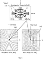
- FIG. 1 is a diagram illustrating a quadrupolar magnetic field, a FFP 130, and a FFL 140, in accordance with certain aspects of the present disclosure.
- An MPI system can produce a quadrupolar magnetic field (upper part of FIG. 1 ) that contains a magnetic null, zero-point or field-free region 120.
- a quadrupolar magnetic field (upper part of FIG. 1 ) that contains a magnetic null, zero-point or field-free region 120.
- the four "poles" 110 of the quadrupolar magnetic field are shown by the short arrows.
- the poles 110 are provided as examples of a magnetic configuration equivalent to the two opposed coils shown in FIG. 1 .
- the poles 110 are located between the two coils in the case where the currents in the coils are equal and opposite.
- the field-free region 120 can be a FFP 130 (as shown by the simplified illustration in the lower left half of FIG. 1 ).
- the field-free region takes the form of a field free line 140 (as shown by the simplified illustration in the lower right half of FIG. 1 ).
- the Y-axis of the plots in FIG. 1 are labeled as vertical to be consistent with later figures, showing the typically vertical orientation of field-free line 140.
- the MPI signal is received from the line, instead of from a point.
- FFL configurations may thus utilize projection-based imaging and reconstruction techniques.
- Field-free line 140 is a generally elongate region, having a length and a thickness, where the magnetic field is significantly lower than at other locations in the magnetic field generated by the MPI system.
- a "field-free line” is understood to account for the reality that the line may not be perfectly straight, nor completely absent magnetic field, but that such is generally the goal of an FFL.
- the field-free line 140 can, in some implementations, be generally elongate or "linear" only within an imaging volume of the MPI system. It is less important for the FFL to maintain linearity outside the imaging volume and thus field-free line 140 may deviate to a different shape away from its center, proximate the center of the imaging volume. Similarly, as used herein, a "field-free point" refers to an approximately spherical region of low magnetic field.
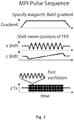
- FIG. 2 is a diagram illustrating an exemplary pulse sequence for moving a FFL 140 in accordance with certain aspects of the present disclosure.
- FFL 140 can be moved to scan different positions in an imaging volume (e.g., around a sample).
- the MPI system can implement a pulse sequence.
- a pulse sequence is a set of actions performed by the MPI scanning hardware.
- the pulse sequence can be designed to image a desired Field of View (FOV) through, for example, movement of FFL 140, movement of the sample 410, movement of the MPI system, or any combination of the above.
- FOV Field of View
- the example pulse sequence illustrated in FIG. 2 includes specifying a magnetic field gradient (shown in the top panel of FIG. 2 ), electronic movement of FFL 140 to cover the field of view (shown in the middle two panels of FIG. 2 ), and fast electronic movement of FFL 140 by an excitation magnet or coil to induce a signal from the sample (shown in the bottom panel of FIG. 2 ).
- the pulse sequence can further include controlling mechanical movement of the sample, movement or rotation of the MPI system, setting an excitation field vector (strength and direction of the magnetic field generated by the excitation magnet or coil), specifying a number and value of angles, or any combination thereof.
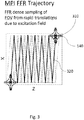
- Figure 3 is a diagram illustrating movement of a FFL 140 along a trajectory 320 during imaging in accordance with certain aspects of the present disclosure.
- the position 310 of FFL 140 can be varied by the combination of magnets in the MPI system by generating a modified magnetic field relative to the quadrupolar field illustrated in FIG. 1 .
- These magnets can include, for example, main magnets or "X magnets” that are configured to generate the FFL 140 and control the X position 310 of FFL 140, shifting magnets or "Z magnets” that are configured to modify or control the gradients around FFL 140 and also shift the Z position 310 of FFL 140.
- An example of the slow variation in position 310 of FFL 140 is illustrated by the zig-zag path in FIG. 3 .
- FFL 140 is moving back and forth in the X direction while generally moving in the Z direction.
- the MPI system can include excitation magnets configured to generate rapid variations in, for example, the X or Z positions of FFL 140 and to excite the particle tracers to generate signal.
- excitation magnets configured to generate rapid variations in, for example, the X or Z positions of FFL 140 and to excite the particle tracers to generate signal.
- FIG. 3 shows that the excitation magnet (driven to move FFL 140 rapidly over a short distance in the Z direction) causes a dense sampling of the scanned imaging area around the slow path created through the X and Z magnets.
- positioning FFL 140 can include varying the position 310 of FFL 140 only in one direction (e.g., the X direction) with a shifting magnet and an excitation magnet. In this example, because there is no variation in an orthogonal direction (e.g., the Z direction), FFL 140 sweeps out a thin slice.
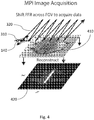
- a slab can be imaged when positioning the FFL 140 includes varying the position of the field free line in both directions orthogonal to the axis of FFL 140 (e.g., varying in both the X direction and in the Z direction). As shown in FIG. 4 , the position 310 of FFL 140 can be varied slowly with, for example, the X magnets and Z magnets. In addition, the excitation magnets (that rapidly move the position 310 of FFL 140 in the X or Z directions) can also add some nominal thickness to the volume imaged with FFL 140.
- FFL 140 trajectory 320 can change depending on the excitation magnetic field vector.
- an excitation field in Z can cover the field of view when rapidly shifted in the X direction.
- an excitation field in the X direction can cover the field of view when rapidly in shifted in the Z direction.
- an excitation field can be produced in both the X and Z directions.
- Figure 4 is a diagram illustrating scanning sample 410 with FFL 140 in two dimensions to generate image 420 in accordance with certain aspects of the present disclosure.
- FFL 140 can be moved across sample 410 rapidly along one axis (e.g., the X axis), and slowly along a second axis (e.g., the Z axis).
- scanning trajectories such as spirals (e.g., where FFL 140 is moved in a spiral pattern in the X-Z plane) and Cartesian grids (e.g., where FFL 140 is moved along X only, and then a short distance along Z, and then back along X in the opposite direction, and so on until a grid-like pattern is formed) are possible.
- image 420 (2D as shown, or 3D in other implementations) can be reconstructed, for example by X-space reconstruction, tomographic methods, etc.
- the number of projections can range from just a few for sparse datasets, to 50 or even a 500+ depending on the level of undersampling or oversampling desired, the strength of the magnetic field gradient, and the tracer particle used. In other implementations, projections can also be acquired using the mechanical movement of the sample 410.
- FIG. 5 is a diagram illustrating a simplified MPI system in accordance with certain aspects of the present disclosure.
- MPI system 500 can include two magnets 510, 520.
- the magnets 510,520 when they have opposing currents, they can generate a quadrupolar magnetic field that includes FFL 140, similar to the example in FIG. 1 .
- FFL 140 can have an FFL axis 540 extending along the length of FFL 140 and passing through FFL center 550 of FFL 140.
- the magnet includes a first magnet 510 and a second magnet 520.
- the present disclosure contemplates that the requisite magnetic field and field free line may be generated by any number, and any type, of magnets.
- the magnet may incorporate multiple magnets (2, 3, 4, etc.) and such magnets can be, for example, a permanent magnet, a current-carrying coil or electromagnet, an electromagnet with a flux return, or any combination of such magnets.
- the magnet may in fact be only a single magnet, to the extent such is capable of generating a field free line (for example, a Halbach cylinder).
- the discussion of the exemplary magnet design herein including two main magnets is not intended to be limiting.
- MPI system 500 can include two or more high-power, water-cooled electromagnets, and two shim magnets (although fewer or more than two shim magnets can be used). Shim magnets can alter the magnetic field, for example to cause a shortening of FFL 140.
- the magnets 510, 520 can be elongate.
- the term "elongate” refers to a geometry where the magnets are longer in one dimension then in another (i.e., not a circular coil). The length of such an elongate configuration can determine, in part, the length of FFL 140.
- MPI systems include an excitation source, an RF detector, and a control system configured to acquire projections according to any of the methods described herein.
- An excitation source can include any type of RF generator, for example, one or more coils or transmit coils, antennas, waveguides that supply RF to FFL 140, and the like.
- a control system can include any combination of hardware and software that is configured to control the operation of the magnets, rotation drivers for the mechanically-rotatable magnet 610, RF receivers or receive coils, and the like. Any of the components of the control system can be configured to work together to enable the methods, mechanical operations, and software operations described herein. The control system can also execute pulse sequences, as described herein.
- FIG. 5 also shows a flux return 530 integrated with the first and second magnets 510 and 520.
- flux return refers to any arrangement of material components that shape the magnetic flux in the manner described herein.
- the flux return 530 may contain, for example, a ferromagnetic material such as iron, or any other material having a low reluctance compared to other materials, such as air, to more efficiently channel, guide, shape, or concentrate magnetic flux.
- the flux return 530 can be, for example, in two halves, or a number of layers of laminates that can be stacked or otherwise assembled to form flux return 530.
- the simplified diagram in FIG. 5 also shows a square aperture in the flux return 530 surrounding the magnets. This aperture can be aligned with the imaging region (or bore) to allow access to the field-free region through the flux return 530.
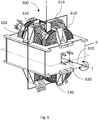
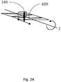
- FIG. 6 is a diagram illustrating an MPI system 600 in accordance with certain aspects of the present disclosure.
- Rotating MPI system 600 includes a mechanically-rotatable magnet 610 that can generate a magnetic field that includes FFL 140 for imaging a sample 410. However, with mechanically-rotatable magnet 610, projections can be acquired at different angles through mechanical rotation.
- the image reconstruction system can be configured to generate a two dimensional image or a three dimensional image.
- Image reconstruction systems can generate an image resolved in all three dimensions based on the projections acquired at different angles.
- a mechanically-rotatable magnet 610 because projections are acquired at different angles, data acquisition and reconstruction methods can be used that differ from data acquisition and reconstruction with a stationary MPI system.
- the magnets can position the field free line at least by the mechanically-rotatable magnet 610 (e.g., a Z magnet, X magnet, shim magnet, or excitation magnet).
- MPI system 600 is similar to MPI system 500, however MPI system 600 includes components (such as mechanically-rotatable magnets 610) configured to rotate about rotation axis 620. As shown in FIG. 6 , MPI system 600 also includes bore 630 that can receive the object that is to be imaged. FFL 140 can extend perpendicularly (here along the Y axis) to the bore 630 (here along the Z axis) though, as described herein, FFL 140 can be shifted in any direction by the application of additional magnetic fields. In some implementations, MPI system 600 can rotate about rotation axis 620 of the bore 630.
- MPI system 600 can rotate about one or more axes of rotation.
- MPI system 600 this refers to any portion of rotatable MPI system 600 that is constructed to rotate around rotation axis 620, and does not imply that every component of MPI system 600 is configured to (or must) rotate to enable the disclosed methods.
- the components of MPI system that can be configured to rotate can include, for example, some or all of the magnets (e.g., main magnets, shifting magnets, shim magnets, excitation magnets), passive shims, flux return, detectors, shielding, cables, a gantry or other support system for any of the above, or any combination the above.
- a "rotation axis 620" refers to any axis that any part of MPI system 600 is configured to rotate about.
- the first magnet 510 and the second magnet 520 and the flux return 530 are shown as capable of rotating about the rotation axis 620, which in this case is the z-axis that extends along the center of the length of the bore 630.
- MPI system 600 can rotate about other axes, which may or may not be an orthogonal X, Y, or Z-axis as shown in FIG. 6 .
- MPI system 600 rotates about rotation axis 620 (e.g., the Z-axis), it is understood that the coordinate system (taken to be in the frame of reference of the MPI system 600 and not a lab frame of reference) correspondingly rotates (e.g., the X axis and Y axis rotate with MPI system 600).
- rotation axis 620 e.g., the Z-axis
- the gantry can be directly driven with a direct drive motor.
- This approach allows accurate control of the magnet position 310.
- the choice of a direct drive motor can be costly, however, and may require the use of a unique motor when requiring a large access hole through the gantry for hoses and current carrying conductors.
- FIG. 7 is a diagram illustrating pinions and gears for direct drive of an MPI system in accordance with certain aspects of the present disclosure.
- the top portion of FIG. 7 shows attachment of the magnet bearing assembly.
- the middle portion of FIG. 7 shows a pinion, gearbox, and servo motor mounted to a backlash adjustment lever arm.
- the bottom portion of FIG. 7 shows a motor and pinion assembly mounted to the frame.
- the pinion to drive a gear tooth approach may be used to rotate MPI system 600.
- the pinion can be driven by a direct drive motor, or by a high accuracy gearbox coupled to a motor.
- the backlash of the pinion to the main gear can be adjusted. This adjustment can be accomplished through the use of a lever arm screw adjustment.
- a hydraulic piston is efficient at moving the magnet, but can require complex linkages in order to enable 180° or 360° rotation.
- the present disclosure contemplates a number of ways of including or excluding components that make up a rotating gantry assembly for rotating an MPI system.
- the magnet is typically mounted to and rotates with the gantry, as rotation of FFL 140 is an aim of the rotating gantry assembly.
- other components such as an RF shielding system and RF receive subsystems are attached to the rotating gantry, and in other designs the RF shield and RF receiver subsystems remain stationary.
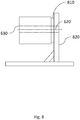
- FIG. 8 is a diagram illustrating an end bearing support for an MPI system in accordance with certain aspects of the present disclosure.
- One approach to supporting a horizontal bore MPI system is to support the magnet from a single end.
- the bore 630 and the rotation axis are centered on the end bearing assembly 810.
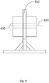
- Figure 9 is a diagram illustrating a center bearing support for an MPI system in accordance with certain aspects of the present disclosure.
- the magnet can also be inserted into a center bearing assembly 910, shown in FIG. 9 .
- the center bearing assembly 910 can be close to the center of gravity of MPI system 600.
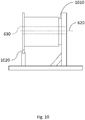
- Figure 10 is a side elevational view illustrating a three bearing support for an MPI system in accordance with certain aspects of the present disclosure.
- Figure 11 is a front elevational view illustrating the three bearing support.
- MPI system 600 can be supported from a first end at a first bearing assembly 1010 and stabilized by the addition of two second bearings assemblies 1020 to support a second opposing end of the MPI system.
- the bearings can press against a plate that is aligned such that it ensures that the centerline of the magnet is also the axis of the rotation. This may be done by attaching the plate to the magnet rotating gantry after manufacturing the magnet gantry.
- the plate is capable of being separately aligned and attached in order to ensure accuracy in alignment of the plate with the rotation axis.
- the plate can be machined in place after manufacturing the rotating gantry to ensure that the outer diameter is concentric with the axis of rotation of the large bearing.
- the substantial weight of the magnet may make it such that the gantry and the support frame bend and ensure that the two small bearing assemblies remain in consistent contact with the round plate throughout the full rotation.
- the small bearing assemblies can be adjusted so that they contact the round plate.
- bearings that can tolerate angular misalignment, such as self-aligning bearings, so that the contact patch is a line.
- An improved contact patch can prevent plastic deformation of the metal plate contact surface since the bearings support a substantial part of the load.
- the large bearing can be designed to support the full weight of the magnet for safety during construction and shipping of the instrument.
- the two small bearings can be designed to be retracted during shipping to prevent vibration and shocks during shipping from indenting the edge of the round plate. Indentation of sufficient magnitude can negatively affect the magnet's ability to produce high-resolution images.
- shipping brackets may be added to the rotating plate and the rear of the gantry to limit motion during shipping in the three instrument axes and the rotation axis.
- An exemplary design of a rotating electromagnet is a magnet that is supported at both ends by bearing assemblies, as shown in FIG. 12 .
- the gantry which contains the magnet and RF shielding, is supported by two smaller bearings that mate with a round plate.
- the gantry is supported by a single large bearing which has a clear bore 630.
- the RF shield box which is mounted to the gantry, extends through the clear bore 630.
- the bearing assemblies can be adjusted up and down.
- Figure 12 is a diagram illustrating two open bore 630 bearing assemblies for an MPI system in accordance with certain aspects of the present disclosure.
- This alternative implementation includes two large bearing assemblies for a horizontal bore magnet, an example of which is shown in FIG. 12 .
- This design may include the use of one standard bearing (e.g., a four point contact ball bearing), and one bearing that can accommodate angular misalignment, such as self-aligning bearings.
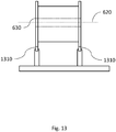
- Figure 13 is a diagram illustrating multiple small bearing assemblies for an MPI system in accordance with certain aspects of the present disclosure.
- the magnet may be supported using three or four small bearing contact surfaces, an example of which is shown in Fig 5 .
- any number of (e.g., three or four) v-groove rollers and matching plates may be used on the magnet.
- Figure 14 is a diagram illustrating a single bearing assembly for a vertical bore 630 MPI system in accordance with certain aspects of the present disclosure.
- the magnet In some magnet designs, it is desirable for the magnet to rotate around a vertical sample 410. This could be the case for two unique scanner concepts including a human breast scanner (accessed from above), or a human brain scanner (accessed from below the magnet, e.g., a patient in a seated position 310). In these cases, the substantial weight of the magnet can be supported on a bearing assembly.
- An exemplary single bearing assembly 1410 for a vertical bore magnet is shown in Fig. 14 .
- Encoder devices for gantry position include printed encoder marks on the gantry itself, or monitoring of the gantry position using a rotary encoder mated to a round plate.
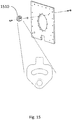
- Figure 15 is a diagram illustrating a mechanical stop in accordance with certain aspects of the present disclosure.
- the magnet preferably includes a mechanical stop 1510 for safety when the magnet has hard-wired connections to supporting equipment (amplifiers, water cooling, etc.).
- the hard stop may be designed in such a way that the magnet can still rotate 360 degrees.
- the hard stop engages with a post on the gantry after the gantry has been rotated beyond 360 degrees, thereby still enabling a full 360 degrees of movement.
- the stop can also incorporate a shock absorber to safely absorb the energy of the system during a fast stop utilizing the mechanical stop.
- Figure 16 is a diagram illustrating a cable track for limited rotation in an MPI system in accordance with certain aspects of the present disclosure.
- a limited rotation system we aim to manage the wire and hoses so that they spool safely and repeatedly with no kinking or binding. This can be done by mounting the wires and hoses in a cable carrier (e.g., IGUS, Inc.) and winding them on a spool.
- a cable carrier e.g., IGUS, Inc.
- An exemplary design is shown in Fig. 16 . In this exemplary design, cables and hoses can be rated for high flex usage.
- the exemplary design shown in Figure 16 specifies a corrugated teflon water hose with a kevlar coating that is suitable for repeated flexing.
- the low noise electrical cables that carry the received signal may benefit from being constructed using low triboelectric noise wiring.
- a cable management system for a limited range rotational system can be one in which the cables associated with the magnet and other components of the gantry system are routed through the center of the bearing and out one end of rotating MPI system 600.
- the cables can then be guided along a windable track that has some flexibility to adapt to the winding of the cables as rotating MPI system 600 turns.
- the cables can then be mated with a stationary interface panel.
- slip rings may be implemented. However, care must be taken as slip rings can introduce noise to MPI system 600 and compromise SNR. Specific design choices that may be considered include brushed slip rings, inductive and capacitive slip rings, liquid metal slip rings, fiber optic slip rings, and water slip rings. For example, high power low frequency magnet currents are well matched to brushed slip rings. The low power signal after the pre-amplifier can be more difficult to transmit to the console, and so multiple options exist to get the signal back while adding little noise.
- cooling fluids e.g., water, fluorinert, galden, or oil
- cooling fluids may also need to be supplied to the magnet and the RF subsystems.
- slip rings e.g., Dynamic Sealing Technologies, Inc.
- typical rotation speed would be approximately 0.5 rotations to 1 rotation per second, which would allow the imager to temporally resolve blood perfusion.
- the routing of the cables and hoses through the system can be complex.
- the hoses and electrical wires are preferably routed through the center of the bearing. This routing is preferred so that the magnet is capable of rotating 360 degrees or continuously rotating without the wires binding with the magnet frame.
- An exemplary design that can be implemented with cables routing through the center of the bearing 1010 is shown in Fig. 10 .
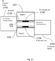
- FIG. 17 is a diagram illustrating a radio frequency (RF) shield 1710 in accordance with certain aspects of the present disclosure.
- the bore 630 can include one or more RF transmit coils 1720 and one or more RF receive coils 1730.
- a radio frequency RF shield 1710 is implemented to electrostatically and magnetically isolate the bore 630 from the external environment.
- an RF shield 1710 is integrated.
- the RF shield 1710 extends through the magnet, from the front to the rear.
- the front of RF shield 1710 holds the RF receivers
- the rear of RF shield 1710 includes the RF transmit filters that provide, for example, high-pass, low-pass, or bandpass filtering of transmitted RF.
- RF shield 1710 can be mounted to rotate with the MPI system. It is contemplated that any part of RF shield 1710 can be mounted to the MPI system.
- RF shield 1710 can include RF shield 1710 (surrounding some or all of bore 630), RF transmit shield 1740 (shielding the RF transmit filter(s)), or RF receive shield 1750 (shielding the RF receive filter(s) and preamplifier(s)). Any combination of the above RF shielding can be implemented.
- any combination of the above RF shielding can be mounted to rotate with the MPI system (not according to the invention) while other portions of the RF shielding remain stationary and do not rotate.
- projections can be acquired while rotating the mechanically-rotatable magnet 610.
- acquisition of projections can include, for example, rotating the mechanically-rotatable magnet 610 to orient the field free line at various angles, positioning FFL 140 at a number of positions at the plurality of angles, and controlling the excitation source and RF detector to acquire signals from magnetic particles in a sample 410 within the field free line.
- the angles at which the magnet may be oriented can be any number and value of angles that MPI system 600 is capable of rotating to.
- the angles can include, for example, 50, 100, 200, or 500 angles spread over a 360° span of rotation of MPI system 600.
- the number and value of the angles can be, for example, predefined (e.g. stored in a computer data file), selected by a user at a user interface, calculated by a control system to provide a desired set of angles for acquiring a particular image at a particular resolution, etc.
- imaging can be performed with different scanning or rotation modes. Some exemplary scanning modes that can provide coverage of a sample 410 are described below.
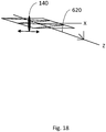
- Figure 18 is a simplified diagram illustrating an example of step-scan imaging in an MPI system in accordance with certain aspects of the present disclosure.
- a step-scan approach acquires projections at a number of angles by rotating the MPI system, fixing the mechanically-rotatable magnet 610 at an angle, and then positioning FFL 140 at a number of different positions to acquire the projections. This process may then be repeated by rotating the magnet to another angle, similarly acquiring projections, and so on.
- FIG. 19 is a diagram illustrating an example of a pulse sequence for step-scan imaging in MPI system 600 in accordance with certain aspects of the present disclosure.
- This pulse sequence is similar to that shown in FIG. 2 , however, the bottom plot shows the progression of the angle of the MPI system 600 over time. As shown, the MPI system is at a first angle, projections are acquired, then imaging halts or pauses while the MPI system is rotated to the next angle, where additional projections are acquired.
- the exemplary positions of FFL 140 are shown in the right portion of FIG. 19 .
- an X-Z plane in the exemplary system rotates around the Z axis with mechanically-rotatable magnet 610. Accordingly, the positions of FFL 140 as shown are similar to those shown for the stationary case.
- acquiring projections at each angle can generate data that an image reconstruction system can utilize to generate an image based on the projections, including three-dimensional images.
- an image reconstruction system can also be configured to create a projection image from a plurality of projections acquired at a fixed angle.
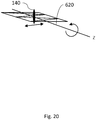
- FIG. 20 is a simplified diagram illustrating an example of an MPI system utilizing continuous rotation in accordance with certain aspects of the present disclosure. As shown in FIG. 20 , in some implementations, positioning FFL 140 at different positions can occur while the mechanically-rotatable magnet 610 is rotating.
- Continuous rotation implementations may include changes in rotational speed, for example speeding up or slowing down, while still rotating the MPI system and acquiring projections.
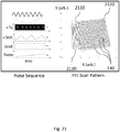
- FIG. 21 is a diagram illustrating a pulse sequence for continuous rotation imaging in accordance with certain aspects of the present disclosure. This pulse sequence is similar to the pulse sequence shown in FIG. 19 , however, instead of the angle being stepped from one value to another, the angle is continuously varied.
- the plot on the right side of FIG. 21 shows a representation of a sequence of FFLs (e.g., simplified as lines in the X-Y plane) as the position of the FFL is shifted in X and continuously rotated in angle.
- the series of lines represent the FFL over a sweep from left to right (shown by the solid lines 2110), to a reversal point 2120, and a sweep from right to left (shown by the dashed lines 2130).
- the solid lines 2110 gradually rotate from vertical (e.g., along with the Y axis) to an angle of about 10° from vertical at reversal point 2120.
- FFL 140 is being rotated by virtue of the rotation of MPI system 600.
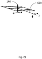
- FIG. 22 is a simplified diagram illustrating an example of back-and-forth imaging in an MPI system in accordance with certain aspects of the present disclosure.
- the field free line is moved through a number of different positions, and is moving through these positions, while the magnet is rotating. At some point, the magnet rotation direction can reverse. Reversal may happen after a rotation of approximately 360°, or at some other angle.
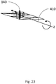
- Figure 23 is a simplified diagram illustrating imaging in an MPI system in accordance with certain aspects of the present disclosure.
- spiral imaging combines the previously described rotation of the magnet while acquiring projections, along with the control system being further configured to move the sample through the bore of the magnet during rotation of the magnet.
- projections can be acquired, as previously discussed, and, after a full set has been acquired, the control system can move the sample along the axis of the bore, and repeat the acquisition of projections.
- the image reconstruction system may be configured to generate a three-dimensional or volumetric image.
- the previously described rotation of the magnet while acquiring projections may be combined with a configuration of the control system that allows for translation of the FFL along the axis of the bore, effected by the magnet itself, and not by physical movement of a portion of the system.
- This translation of the FFL may be done during rotation of the magnet, or only after a full-rotation dataset is acquired (in step-like fashion).
- the data acquired in such implementations can likewise be utilized by the image reconstruction system to create a three-dimensional or volumetric image.
- the magnet is rotated while projections are acquired and the positions of the field free line vary only in the one direction.
- FFL positions may be varied only in the X direction, and the excitation source may only excite or move the FFL in the X direction as well.
- This method of data acquisition may be particularly useful for rapid perfusion or functional MPI imaging of a thin slice of a subject.
- the magnet is rotated while projections are acquired and the positions of the field free line are varied in two directions.
- FFL positions may be varied in both the X and Z directions, and the excitation source may excite or move the FFL in both the X and Z directions as well.
- shim magnet(s) may be used to counteract the normal flux distribution around the main magnet and thereby reshape the FFL into different forms, for example, into an approximation of a field-free point, or into an ellipsoidal field-free region. Utilization of such alternatively shaped FFLs (such as an ellipsoid) to acquire projections during magnet rotation may enable beneficial slab-type imaging.
- One or more aspects or features of the subject matter described herein can be realized in digital electronic circuitry, integrated circuitry, specially designed application specific integrated circuits (ASICs), field programmable gate arrays (FPGAs) computer hardware, firmware, software, and/or combinations thereof.
- ASICs application specific integrated circuits
- FPGAs field programmable gate arrays
- These various aspects or features can include implementation in one or more computer programs that are executable and/or interpretable on a programmable system including at least one programmable processor, which can be special or general purpose, coupled to receive data and instructions from, and to transmit data and instructions to, a storage system, at least one input device, and at least one output device.
- the programmable system or computing system may include clients and servers.
- a client and server are generally remote from each other and typically interact through a communication network. The relationship of client and server arises by virtue of computer programs running on the respective computers and having a client-server relationship to each other.
- machine-readable signal refers to any signal used to provide machine instructions and/or data to a programmable processor.
- the machine-readable medium can store such machine instructions non-transitorily, such as for example as would a non-transient solid-state memory or a magnetic hard drive or any equivalent storage medium.
- the machine-readable medium can alternatively or additionally store such machine instructions in a transient manner, such as for example as would a processor cache or other random access memory associated with one or more physical processor cores.
- one or more aspects or features of the subject matter described herein can be implemented on a computer having a display device, such as for example a cathode ray tube (CRT) or a liquid crystal display (LCD) or a light emitting diode (LED) monitor for displaying information to the user and a keyboard and a pointing device, such as for example a mouse or a trackball, by which the user may provide input to the computer.
- a display device such as for example a cathode ray tube (CRT) or a liquid crystal display (LCD) or a light emitting diode (LED) monitor for displaying information to the user
- LCD liquid crystal display
- LED light emitting diode
- a keyboard and a pointing device such as for example a mouse or a trackball
- feedback provided to the user can be any form of sensory feedback, such as for example visual feedback, auditory feedback, or tactile feedback; and input from the user may be received in any form, including, but not limited to, acoustic, speech, or tactile input.
- Other possible input devices include, but are not limited to, touch screens or other touch-sensitive devices such as single or multi-point resistive or capacitive trackpads, voice recognition hardware and software, optical scanners, optical pointers, digital image capture devices and associated interpretation software, and the like.
- phrases such as "at least one of” or “one or more of” may occur followed by a conjunctive list of elements or features.
- the term “and/or” may also occur in a list of two or more elements or features. Unless otherwise implicitly or explicitly contradicted by the context in which it used, such a phrase is intended to mean any of the listed elements or features individually or any of the recited elements or features in combination with any of the other recited elements or features.
- the phrases “at least one of A and B;” “one or more of A and B;” and “A and/or B” are each intended to mean "A alone, B alone, or A and B together.”
- a similar interpretation is also intended for lists including three or more items.
- phrases “at least one of A, B, and C;” “one or more of A, B, and C;” and “A, B, and/or C” are each intended to mean “A alone, B alone, C alone, A and B together, A and C together, B and C together, or A and B and C together.”
- Use of the term “based on,” above and in the claims is intended to mean, “based at least in part on,” such that an unrecited feature or element is also permissible.
- section headings shall not limit or characterize the invention(s) set out in any claims that may issue from this disclosure. Specifically, and by way of example, although the headings refer to a "Technical Field,” such claims should not be limited by the language chosen under this heading to describe the so-called technical field. Further, the description of a technology in the "Background” is not to be construed as an admission that technology is prior art to any invention(s) in this disclosure. Neither is the “Summary” to be considered as a characterization of the invention(s) set forth in issued claims.
Landscapes
- Physics & Mathematics (AREA)
- Health & Medical Sciences (AREA)
- Life Sciences & Earth Sciences (AREA)
- General Physics & Mathematics (AREA)
- Condensed Matter Physics & Semiconductors (AREA)
- Chemical & Material Sciences (AREA)
- Engineering & Computer Science (AREA)
- Nuclear Medicine, Radiotherapy & Molecular Imaging (AREA)
- Pathology (AREA)
- General Health & Medical Sciences (AREA)
- Medical Informatics (AREA)
- Public Health (AREA)
- Biomedical Technology (AREA)
- Heart & Thoracic Surgery (AREA)
- Radiology & Medical Imaging (AREA)
- Molecular Biology (AREA)
- Surgery (AREA)
- Animal Behavior & Ethology (AREA)
- Nanotechnology (AREA)
- Biophysics (AREA)
- Veterinary Medicine (AREA)
- Chemical Kinetics & Catalysis (AREA)
- Electrochemistry (AREA)
- Analytical Chemistry (AREA)
- Biochemistry (AREA)
- Immunology (AREA)
- Magnetic Resonance Imaging Apparatus (AREA)
- Measurement And Recording Of Electrical Phenomena And Electrical Characteristics Of The Living Body (AREA)
- Apparatus For Radiation Diagnosis (AREA)
- Magnetic Treatment Devices (AREA)
Claims (16)
- Système d'imagerie à particules magnétiques (IMP) à auto-protection (600) comprenant:un aimant à rotation mécanique (610) configuré pour générer un champ magnétique comprenant une ligne de champ libre (140) ;une source d'excitation ;un détecteur RF ;un blindage RF (1710) entourant une partie ou l'ensemble d'un alésage du système IMP à auto-protection, le blindage RF (1710) étant intégré dans le système IMP, fournissant ainsi ladite auto-protection ; etun système de commande configuré acquiert une pluralité de projections à une pluralité d'angles, l'acquisition comprenant :la rotation de l'aimant à rotation mécanique (610) pour orienter la ligne de champ libre (140) à la pluralité d'angles ;le positionnement de la ligne de champ libre (140) sur une pluralité de positions à la pluralité d'angles ; etla commande de la source d'excitation et du détecteur RF pour acquérir des signaux à partir de particules magnétiques dans un échantillon à l'intérieur de la ligne de champ libre (140) sur la pluralité de positions ; etun système de reconstruction d'image configuré pour générer une image sur base au moins de la pluralité de projections,dans lequel le blindage RF (1710) est configuré pour rester immobile durant la rotation de l'aimant à rotation mécanique (610).
- Système selon la revendication 1, dans lequel le positionnement de la ligne de champ libre (140) sur une pluralité de positions se produit lorsque l'aimant à rotation mécanique (610) est fixé à un angle.
- Système selon la revendication 2, dans lequel le système de reconstruction d'image est en outre configuré pour créer l'image à partir d'une pluralité de projections acquises à un angle fixe.
- Système selon la revendication 1, dans lequel le positionnement de la ligne de champ libre (140) sur une pluralité de positions se produit alors que l'aimant à rotation mécanique tourne.
- Système selon la revendication 4, dans lequel la rotation de l'aimant à rotation mécanique (610) comprend l'inversion du sens de rotation durant l'acquisition de la pluralité de projections.
- Système selon la revendication 4, dans lequel le système de commande est en outre configuré pour déplacer l'échantillon à travers un alésage de l'aimant à rotation mécanique (610) durant l'acquisition.
- Système selon la revendication 1, dans lequel le système de commande est en outre configuré pour déplacer l'échantillon à travers un alésage de l'aimant à rotation mécanique (610) et acquérir une pluralité supplémentaire de projections à une autre pluralité d'angles.
- Système selon la revendication 1, dans lequel le système de commande est en outre configuré pour déplacer électroniquement la ligne de champ libre (140) le long d'un axe de rotation de l'aimant à rotation mécanique (610) et acquérir une pluralité supplémentaire de projections à une autre pluralité d'angles.
- Système selon la revendication 1, dans lequel le positionnement de la ligne de champ libre sur une pluralité de positions est accompli au moins par l'aimant à rotation mécanique (610) générant un champ magnétique modifié.
- Système selon la revendication 1, dans lequel le positionnement de la ligne de champ libre (140) dans une pluralité de positions comprend la variation de la position de la ligne de champ libre (140) uniquement dans la direction X avec un aimant de décalage et un aimant d'excitation.
- Système selon la revendication 1, dans lequel le positionnement de la ligne de champ libre (140) dans une pluralité de positions comprend la variation de la position de la ligne de champ libre (140) à la fois dans la direction X et dans la direction Z avec au moins un aimant et avec au moins un aimant d'excitation.
- Système selon la revendication 1, comprenant en outre au moins un aimant de compensation configuré pour modifier le champ magnétique.
- Système selon la revendication 12, dans lequel la modification du champ magnétique provoque un élargissement de la ligne de champ libre (140).
- Système selon la revendication 1, dans lequel le système de commande est en outre configuré pour établir un vecteur de champ d'excitation qui spécifie une intensité et une direction d'un champ magnétique généré par la source d'excitation.
- Système selon la revendication 1, dans lequel l'aimant à rotation mécanique (610) est couplé à une ou plusieurs bagues collectrices pour permettre une rotation continue de l'aimant à rotation mécanique.
- Système selon la revendication 15, dans lequel la ou les bagues collectrices comprennent une ou plusieurs parmi : une bague collectrice capacitive, une bague collectrice inductive et une bague collectrice optique, ou une bague collectrice numérique.
Applications Claiming Priority (3)
| Application Number | Priority Date | Filing Date | Title |
|---|---|---|---|
| US201662361463P | 2016-07-12 | 2016-07-12 | |
| US201662361475P | 2016-07-12 | 2016-07-12 | |
| PCT/US2017/041792 WO2018013738A1 (fr) | 2016-07-12 | 2017-07-12 | Imagerie à particules magnétiques employant un aimant rotatif |
Publications (2)
| Publication Number | Publication Date |
|---|---|
| EP3484357A1 EP3484357A1 (fr) | 2019-05-22 |
| EP3484357B1 true EP3484357B1 (fr) | 2021-04-14 |
Family
ID=59388183
Family Applications (3)
| Application Number | Title | Priority Date | Filing Date |
|---|---|---|---|
| EP22181395.9A Pending EP4085827A1 (fr) | 2016-07-12 | 2017-07-12 | Magerie de particules magnétiques |
| EP17743441.2A Active EP3484358B1 (fr) | 2016-07-12 | 2017-07-12 | Imagerie à particules magnétiques utilisant un aimant de retour |
| EP17743158.2A Active EP3484357B1 (fr) | 2016-07-12 | 2017-07-12 | Imagerie à particules magnétiques employant un aimant rotatif |
Family Applications Before (2)
| Application Number | Title | Priority Date | Filing Date |
|---|---|---|---|
| EP22181395.9A Pending EP4085827A1 (fr) | 2016-07-12 | 2017-07-12 | Magerie de particules magnétiques |
| EP17743441.2A Active EP3484358B1 (fr) | 2016-07-12 | 2017-07-12 | Imagerie à particules magnétiques utilisant un aimant de retour |
Country Status (5)
| Country | Link |
|---|---|
| US (3) | US10466316B2 (fr) |
| EP (3) | EP4085827A1 (fr) |
| JP (3) | JP7097879B2 (fr) |
| CN (3) | CN109937005B (fr) |
| WO (2) | WO2018013738A1 (fr) |
Families Citing this family (18)
| Publication number | Priority date | Publication date | Assignee | Title |
|---|---|---|---|---|
| US10466316B2 (en) | 2016-07-12 | 2019-11-05 | Magnetic Insight, Inc. | Magnetic particle imaging |
| JP6887567B2 (ja) * | 2018-05-21 | 2021-06-16 | 三菱電機株式会社 | 磁気粒子イメージング用電磁石装置および磁気粒子イメージング装置 |
| WO2020186185A1 (fr) * | 2019-03-13 | 2020-09-17 | Magnetic Insight, Inc. | Actionnement de particules magnétiques |
| CN110367983B (zh) * | 2019-07-15 | 2020-09-22 | 中国科学院自动化研究所 | 基于无磁场线扫描的磁粒子成像系统 |
| DE102020202097B3 (de) * | 2020-02-19 | 2021-04-08 | Bruker Biospin Mri Gmbh | MPI-Bildgebungsvorrichtung, Verfahren zur Erzeugung eines Magnetfelds mit einem Gradienten und einer feldfreien Linie mittels einer MPI-Bildgebungsvorrichtung |
| KR102545062B1 (ko) | 2020-06-25 | 2023-06-20 | 한국전자통신연구원 | 나노 자성 입자 영상화 장치 및 방법 |
| DE102020211948B3 (de) | 2020-09-23 | 2021-10-14 | Bruker Biospin Mri Gmbh | Magnetanordnung zur Erzeugung eines Selektionsmagnetfelds, Vorrichtung mit Magnetanordnung und Verfahren zur Erzeugung eines Selektionsmagnetfelds |
| KR102655930B1 (ko) * | 2020-09-24 | 2024-04-11 | 한국전자통신연구원 | 필드프리 생성 장치, 나노 자성 입자 영상화 장치 및 방법 |
| CN112635152A (zh) * | 2020-12-14 | 2021-04-09 | 瑞声精密制造科技(常州)有限公司 | 环形阵列磁钢系统及磁吸定位系统 |
| CN113288106B (zh) * | 2021-05-24 | 2022-11-15 | 中国科学院自动化研究所 | 磁粒子成像检测系统、方法、电子设备 |
| CN113397521B (zh) * | 2021-06-15 | 2022-05-27 | 中国科学院自动化研究所 | 螺旋扫描磁粒子投影断层成像方法、系统、设备 |
| CN117916608A (zh) * | 2021-09-14 | 2024-04-19 | 三菱电机株式会社 | 磁微粒成像装置 |
| US11940502B2 (en) * | 2021-09-24 | 2024-03-26 | Analog Devices International Unlimited Company | Magnetic field sensing based on particle position within container |
| US11733324B2 (en) | 2021-09-24 | 2023-08-22 | Mitsubishi Electric Corporation | Magnetic particle imaging system and magnetic particle imaging method |
| CN114521882B (zh) * | 2022-04-22 | 2022-07-19 | 北京航空航天大学 | 基于磁粒子的无场线扫描成像和无场点定位热疗融合装置 |
| CN114521881B (zh) * | 2022-04-22 | 2022-07-19 | 北京航空航天大学 | 基于无场线有惯性扫描的磁粒子成像和热疗融合的装置 |
| CN115778354B (zh) * | 2023-02-07 | 2023-04-28 | 北京航空航天大学 | 基于径向-笛卡尔轨迹扫描的人体尺度闭孔式mpi装置 |
| CN115792747B (zh) * | 2023-02-13 | 2023-04-28 | 北京航空航天大学 | 多模态磁粒子成像的固定及配准标定系统 |
Family Cites Families (70)
| Publication number | Priority date | Publication date | Assignee | Title |
|---|---|---|---|---|
| US1567423A (en) | 1925-02-02 | 1925-12-29 | George L Comlossy | Drain seal for refrigerator cars |
| JPS59155239A (ja) | 1983-02-23 | 1984-09-04 | 株式会社東芝 | 診断用核磁気共鳴装置 |
| US4538130A (en) | 1984-04-23 | 1985-08-27 | Field Effects, Inc. | Tunable segmented ring magnet and method of manufacture |
| JPH01209706A (ja) * | 1988-02-17 | 1989-08-23 | Kobe Steel Ltd | 磁極構造 |
| DE3821984A1 (de) | 1988-06-30 | 1990-04-12 | Philips Patentverwaltung | Schaltungsanordnung zur erzeugung von hochfrequenzsignalen fuer kernspinuntersuchungen |
| US5461282A (en) * | 1993-02-05 | 1995-10-24 | Litton Systems, Inc. | Advanced center post electron gun |
| US5510711A (en) | 1994-08-05 | 1996-04-23 | Picker International, Inc. | Digital combination and correction of quadrature magnetic resonance receiver coils |
| GB9506909D0 (en) | 1995-04-04 | 1995-05-24 | Scient Generics Ltd | Spatial magnetic interrogation system |
| US5606254A (en) * | 1995-10-19 | 1997-02-25 | General Motors Corporation | Rotation sensor employing coil wound on assembly of a core interposed between two magnets |
| GB9608329D0 (en) | 1996-04-23 | 1996-06-26 | Scient Genarics Ltd | Improved methods for coding magnetic tags |
| AU717499B2 (en) | 1996-06-19 | 2000-03-30 | Flying Null Limited | Magnetic sensing and reading devices |
| GB9619896D0 (en) | 1996-09-24 | 1996-11-06 | Flying Null Ltd | Improvements in or relating to magnetic sensors |
| GB9620190D0 (en) | 1996-09-27 | 1996-11-13 | Flying Null Ltd | Improved methods for coding magnetic tags |
| CN1133080C (zh) | 1996-10-09 | 2003-12-31 | 飞零有限公司 | 用于检测磁标记体的读取器 |
| GB9717574D0 (en) | 1997-08-19 | 1997-10-22 | Flying Null Ltd | Catheter location |
| DE69822841T2 (de) | 1997-08-19 | 2005-04-21 | Flying Null Ltd | Verbesserung in bezug auf chirurgiegeräte und ihre lokalisierung |
| GB9800064D0 (en) | 1998-01-05 | 1998-03-04 | Sentec Ltd | Uni-directional magnetic tag |
| GB9805824D0 (en) | 1998-03-18 | 1998-05-13 | Flying Null Ltd | Magnetic patterns |
| GB9806923D0 (en) | 1998-03-31 | 1998-05-27 | Flying Null Ltd | Position sensing |
| GB9817803D0 (en) | 1998-08-14 | 1998-10-14 | Flying Null Ltd | Magnetic information carriers |
| DE69909842T2 (de) | 1998-12-23 | 2004-01-29 | Flying Null Ltd | Lesevorrichtungen für magnetische etiketten |
| US7022987B2 (en) * | 2001-02-20 | 2006-04-04 | Carl Zeiss Nis Gmbh | Particle-optical arrangements and particle-optical systems |
| DE10151778A1 (de) | 2001-10-19 | 2003-05-08 | Philips Corp Intellectual Pty | Verfahren zur Ermittlung der räumlichen Verteilung magnetischer Partikel |
| DE10238853A1 (de) | 2002-08-24 | 2004-03-04 | Philips Intellectual Property & Standards Gmbh | Verfahren zur lokalen Erwärmung mit magnetischen Partikeln |
| EP2335573B1 (fr) * | 2003-04-15 | 2013-08-21 | Philips Intellectual Property & Standards | Kit de compositions de particules magnétiques et composition de particules magnétiques fonctionnalisées |
| US7351194B2 (en) | 2003-04-15 | 2008-04-01 | Koninklijke Philips Electronics N.V. | Arrangement for influencing magnetic particles |
| WO2004091395A2 (fr) | 2003-04-15 | 2004-10-28 | Philips Intellectual Property & Standards Gmbh | Procede de determination par resolution spatiale de la repatition de particules magnetiques dans une zone d'examen |
| JP4583369B2 (ja) | 2003-04-15 | 2010-11-17 | コーニンクレッカ フィリップス エレクトロニクス エヌ ヴィ | 磁性粒子に影響を与える方法及び装置 |
| US20060248944A1 (en) | 2003-04-15 | 2006-11-09 | Koninklijke Philips Electronics N.V. | Method to determine the spatial distribution of magnetic particles and magnetic particle administering compositions |
| US20050073309A1 (en) | 2003-10-01 | 2005-04-07 | Williams Neil R. | Magnetic resonance coil modules |
| US20070258908A1 (en) | 2006-04-27 | 2007-11-08 | Lanza Gregory M | Detection and imaging of target tissue |
| CN101563032B (zh) * | 2006-12-20 | 2013-02-13 | 皇家飞利浦电子股份有限公司 | 用于影响和/或检测作用区域中的磁性粒子的方法和布置 |
| WO2008078242A2 (fr) | 2006-12-20 | 2008-07-03 | Philips Intellectual Property & Standards Gmbh | Dispositif et procédé permettant d'influencer et/ou de détecter des particules magnétiques dans une zone d'action |
| JP2010512916A (ja) | 2006-12-20 | 2010-04-30 | コーニンクレッカ フィリップス エレクトロニクス エヌ ヴィ | 作用領域の磁性粒子に影響を及ぼし、及び/又は該磁性粒子を検出する装置並びに方法 |
| CN101626725B (zh) | 2007-02-15 | 2011-08-10 | 皇家飞利浦电子股份有限公司 | 用于磁性粒子成像的设备、用于影响和/或检测多个和单个磁性粒子的方法 |
| DE102007009210A1 (de) | 2007-02-26 | 2008-08-28 | Siemens Ag | Bildgebendes tomographisches Verfahren und zugehörige Anordnung |
| JP5100212B2 (ja) | 2007-06-15 | 2012-12-19 | 株式会社東芝 | 磁性微粒子イメージング装置、検出コイル配設方法および磁束検出装置 |
| US7994786B2 (en) | 2007-06-19 | 2011-08-09 | Mary Hitchcock Memorial Hospital | System and method for use of nanoparticles in imaging and temperature measurement |
| US8954131B2 (en) | 2007-06-19 | 2015-02-10 | The Trustees Of Dartmouth College | Magnetic particle imaging (MPI) system and method for use of iron-based nanoparticles in imaging and diagnosis |
| US8884617B2 (en) | 2008-06-23 | 2014-11-11 | The Regents Of The University Of California | Magnetic particle imaging devices and methods |
| US8847592B2 (en) * | 2008-06-23 | 2014-09-30 | The Regents Of The University Of California | Techniques for magnetic particle imaging |
| CN102245097B (zh) * | 2008-12-10 | 2014-07-09 | 皇家飞利浦电子股份有限公司 | 具有可变选择场取向的用于磁性粒子成像的设备 |
| EP2223719A1 (fr) * | 2009-02-27 | 2010-09-01 | Koninklijke Philips Electronics N.V. | Appareil thérapeutique pour traiter un sujet utilisant des nanoparticules magnétiques |
| EP2427108A1 (fr) | 2009-05-08 | 2012-03-14 | Koninklijke Philips Electronics N.V. | Dispositif et procédé de chauffage d'un matériau magnétique |
| WO2010134006A2 (fr) | 2009-05-18 | 2010-11-25 | Koninklijke Philips Electronics N.V. | Système et procédé permettant d'influencer et/ou de détecter des particules magnétiques |
| JP5763631B2 (ja) | 2009-07-01 | 2015-08-12 | コーニンクレッカ フィリップス エヌ ヴェ | Mpi誘導による薬物送達のための刺激応答性キャリア |
| RU2542780C2 (ru) | 2009-07-20 | 2015-02-27 | Конинклейке Филипс Электроникс Н.В. | Устройство и способ для оказания влияния и обнаружения магнитных частиц |
| US9192320B2 (en) * | 2009-09-11 | 2015-11-24 | Koninklijke Philips N.V. | Apparatus and method for influencing and/or detecting magnetic particles in a field of view |
| EP2477543B1 (fr) | 2009-09-14 | 2013-08-28 | Koninklijke Philips Electronics N.V. | Appareil et procede de deplacement et d'activation d'un agent actif |
| WO2011116229A2 (fr) | 2010-03-17 | 2011-09-22 | The Regents Of The University Of California | Dispositifs et procédés d'imagerie de particules magnétiques |
| EP2452622A1 (fr) * | 2010-11-11 | 2012-05-16 | Philips Intellectual Property & Standards GmbH | Examen du côlon à l'aide d'imagerie de particules magnétiques |
| BR112013013882A2 (pt) * | 2010-12-10 | 2016-09-13 | Koninkl Philips Electronics Nv | aparelho para operação em um modo de imagem da partículas magnética para influenciar e/ou detectar partículas magnéticas em um campo de visão e para operação em um modo de imagem de ressonância magnética, método para operar um aparelho e programa de computador |
| US20120190979A1 (en) | 2011-01-24 | 2012-07-26 | Actium BioSystems, LLC | System for automatically amending energy field characteristics in the application of an energy field to a living organism for treatment of invasive agents |
| US8968171B2 (en) | 2011-01-24 | 2015-03-03 | Endomagnetics Limited | System for correlating energy field characteristics with target particle characteristics in the application of an energy field to a living organism for imaging and treatment of invasive agents |
| US8757166B2 (en) | 2011-01-24 | 2014-06-24 | Actium BioSystems, LLC | System for defining energy field characteristics to illuminate nano-particles used to treat invasive agents |
| US20120265050A1 (en) | 2011-04-04 | 2012-10-18 | Ge Wang | Omni-Tomographic Imaging for Interior Reconstruction using Simultaneous Data Acquisition from Multiple Imaging Modalities |
| RU2635653C2 (ru) | 2011-08-26 | 2017-11-14 | Эндомагнетикс Лтд | Устройство для генерирования энергетического поля для лечения рака полостей тела и полостных органов тела |
| US9622809B2 (en) * | 2011-09-23 | 2017-04-18 | Weinberg Medical Physics Inc | Apparatus and method for spatially selective interventional neuroparticles |
| BR112014011533A2 (pt) * | 2011-11-16 | 2017-05-09 | Koninklijke Philips Nv | aparelho de influência e/ou detecção de partículas magnéticas em um campo de visão |
| EP2748623B1 (fr) * | 2011-12-02 | 2016-09-07 | Koninklijke Philips N.V. | Agencement de bobine pour mpi |
| BR112014014284A2 (pt) * | 2011-12-15 | 2017-06-13 | Koninklijke Philips Nv | aparelho e método para detecção de partículas magnéticas em um campo de visão, e, programa de computador |
| CN104619249B (zh) * | 2012-09-14 | 2017-09-15 | 布鲁克碧奥斯平Mri有限公司 | 用于产生满足mpi以及mri要求的磁场分布的装置 |
| US10222438B2 (en) | 2012-11-01 | 2019-03-05 | The Trustees Of Dartmouth College | System and apparatus for combined magnetic resonance imaging with magnetic spectroscopy of brownian motion and/or magnetic nanoparticle imaging |
| EP2916731A1 (fr) * | 2012-11-07 | 2015-09-16 | Koninklijke Philips N.V. | Dispositif magnétique pour utilisation dans un appareil d'imagerie de particules magnétiques (mpi) |
| DE102012221838B3 (de) * | 2012-11-29 | 2014-04-30 | Bruker Biospin Mri Gmbh | Vorrichtung zur sequenziellen Untersuchung eines Messobjektes mittels der Verfahren MPI als auch MRI |
| US9846206B2 (en) * | 2012-12-10 | 2017-12-19 | General Electric Company | Systems and methods for magnetic material imaging |
| EP3043703A1 (fr) * | 2013-09-11 | 2016-07-20 | Koninklijke Philips N.V. | Appareil d'imagerie mpi avec mouvement rapide du champ de vision |
| AU2016203678A1 (en) | 2015-06-02 | 2016-12-22 | Endomagnetics Ltd. | Multicore magnetic particles |
| EP3374779B1 (fr) * | 2015-11-12 | 2021-03-03 | University of Massachusetts | Appareil et procédé pour le codage spatial de dispositifs d'ipm basés sur ffl |
| US10466316B2 (en) | 2016-07-12 | 2019-11-05 | Magnetic Insight, Inc. | Magnetic particle imaging |
-
2017
- 2017-07-12 US US15/648,421 patent/US10466316B2/en active Active
- 2017-07-12 CN CN201780053587.4A patent/CN109937005B/zh active Active
- 2017-07-12 US US15/648,403 patent/US10775452B2/en active Active
- 2017-07-12 CN CN202310779666.0A patent/CN116807441A/zh active Pending
- 2017-07-12 CN CN201780053595.9A patent/CN109952060B/zh active Active
- 2017-07-12 WO PCT/US2017/041792 patent/WO2018013738A1/fr unknown
- 2017-07-12 EP EP22181395.9A patent/EP4085827A1/fr active Pending
- 2017-07-12 EP EP17743441.2A patent/EP3484358B1/fr active Active
- 2017-07-12 JP JP2019522617A patent/JP7097879B2/ja active Active
- 2017-07-12 WO PCT/US2017/041783 patent/WO2018013731A1/fr unknown
- 2017-07-12 EP EP17743158.2A patent/EP3484357B1/fr active Active
- 2017-07-12 US US15/648,401 patent/US11204398B2/en active Active
- 2017-07-12 JP JP2019522618A patent/JP7097357B2/ja active Active
-
2022
- 2022-06-28 JP JP2022104008A patent/JP2022126838A/ja active Pending
Non-Patent Citations (1)
| Title |
|---|
| MATTHIAS WEBER ET AL.: "P17 TECHNICAL ASPECTS OF A TWO DIMENSIONAL ROTATABLE FIELDFREE LINE IMAGER FOR MAGNETIC PARTICLE IMAGING", 4TH INTERNATIONAL WORKSHOP ON MAGNETIC PARTICLE IMAGING, 28 March 2014 (2014-03-28), pages - 99, Retrieved from the Internet <URL:http://doc.utwente.nl/94650/1/IWMPI2014_Book_of_Abstracts.pdf> [retrieved on 20161110] * |
Also Published As
| Publication number | Publication date |
|---|---|
| CN116807441A (zh) | 2023-09-29 |
| JP7097357B2 (ja) | 2022-07-07 |
| EP3484358B1 (fr) | 2022-06-29 |
| WO2018013731A1 (fr) | 2018-01-18 |
| JP7097879B2 (ja) | 2022-07-08 |
| CN109937005B (zh) | 2023-08-08 |
| WO2018013738A1 (fr) | 2018-01-18 |
| US20180017639A1 (en) | 2018-01-18 |
| US20180017641A1 (en) | 2018-01-18 |
| CN109952060A (zh) | 2019-06-28 |
| US11204398B2 (en) | 2021-12-21 |
| CN109937005A (zh) | 2019-06-25 |
| JP2019523115A (ja) | 2019-08-22 |
| CN109952060B (zh) | 2023-07-18 |
| US10466316B2 (en) | 2019-11-05 |
| EP3484358A1 (fr) | 2019-05-22 |
| JP2019527606A (ja) | 2019-10-03 |
| EP3484357A1 (fr) | 2019-05-22 |
| US20180017640A1 (en) | 2018-01-18 |
| JP2022126838A (ja) | 2022-08-30 |
| EP4085827A1 (fr) | 2022-11-09 |
| US10775452B2 (en) | 2020-09-15 |
Similar Documents
| Publication | Publication Date | Title |
|---|---|---|
| EP3484357B1 (fr) | Imagerie à particules magnétiques employant un aimant rotatif | |
| CN103800009B (zh) | 组合的磁共振成像和放射治疗系统 | |
| JP6018185B2 (ja) | Mri放射線治療装置の静磁場補正 | |
| US10261141B2 (en) | Apparatus and methods for spatial encoding of FFL-based MPI devices | |
| JP2021524775A (ja) | 磁気共鳴結像システム用のb0磁石の機器および方法 | |
| US10656224B2 (en) | Magnetic field-generating device for magnetic particle imaging | |
| US20100174172A1 (en) | Mri system for upright radiotherapy | |
| CN110420026A (zh) | 基于ffl的磁粒子成像三维立体重建方法、系统、装置 | |
| WO2014154861A1 (fr) | Marqueurs, fantômes et procédés associés de calibrage de systèmes d'imagerie | |
| KR101128045B1 (ko) | 전자기장을 이용한 드릴링 마이크로로봇 시스템 | |
| EP3011354B1 (fr) | Système correcteur de champ magnétique destiné à un scanner hybride à résonance magnétique | |
| CN102481118A (zh) | 用于移动和激活活性剂的设备和方法 | |
| CN112684391A (zh) | 混合成像装置和/或用于设计磁体布置结构的方法 | |
| Liu et al. | A new transmission mechanism for the actuation of manipulators for magnetic resonance imaging (MRI) guided interventions | |
| JP2016178967A (ja) | 磁気共鳴イメージング装置 | |
| CN116990734A (zh) | 一种基于静磁场偏心运动的三维磁粒子成像系统和方法 | |
| An et al. | Manipulator‐driven selection of semi‐active MR‐visible markers | |
| CN117434483A (zh) | 一种磁场发生装置及磁粒子成像系统 | |
| JP2019505254A (ja) | 陽子線療法のための回転可能磁石 |
Legal Events
| Date | Code | Title | Description |
|---|---|---|---|
| STAA | Information on the status of an ep patent application or granted ep patent |
Free format text: STATUS: UNKNOWN |
|
| STAA | Information on the status of an ep patent application or granted ep patent |
Free format text: STATUS: THE INTERNATIONAL PUBLICATION HAS BEEN MADE |
|
| PUAI | Public reference made under article 153(3) epc to a published international application that has entered the european phase |
Free format text: ORIGINAL CODE: 0009012 |
|
| STAA | Information on the status of an ep patent application or granted ep patent |
Free format text: STATUS: REQUEST FOR EXAMINATION WAS MADE |
|
| 17P | Request for examination filed |
Effective date: 20190207 |
|
| AK | Designated contracting states |
Kind code of ref document: A1 Designated state(s): AL AT BE BG CH CY CZ DE DK EE ES FI FR GB GR HR HU IE IS IT LI LT LU LV MC MK MT NL NO PL PT RO RS SE SI SK SM TR |
|
| AX | Request for extension of the european patent |
Extension state: BA ME |
|
| DAV | Request for validation of the european patent (deleted) | ||
| DAX | Request for extension of the european patent (deleted) | ||
| STAA | Information on the status of an ep patent application or granted ep patent |
Free format text: STATUS: EXAMINATION IS IN PROGRESS |
|
| 17Q | First examination report despatched |
Effective date: 20200121 |
|
| RAP1 | Party data changed (applicant data changed or rights of an application transferred) |
Owner name: MAGNETIC INSIGHT, INC. |
|
| RIN1 | Information on inventor provided before grant (corrected) |
Inventor name: GOODWILL, PATRICK W. |
|
| GRAP | Despatch of communication of intention to grant a patent |
Free format text: ORIGINAL CODE: EPIDOSNIGR1 |
|
| STAA | Information on the status of an ep patent application or granted ep patent |
Free format text: STATUS: GRANT OF PATENT IS INTENDED |
|
| INTG | Intention to grant announced |
Effective date: 20201023 |
|
| GRAS | Grant fee paid |
Free format text: ORIGINAL CODE: EPIDOSNIGR3 |
|
| GRAA | (expected) grant |
Free format text: ORIGINAL CODE: 0009210 |
|
| STAA | Information on the status of an ep patent application or granted ep patent |
Free format text: STATUS: THE PATENT HAS BEEN GRANTED |
|
| AK | Designated contracting states |
Kind code of ref document: B1 Designated state(s): AL AT BE BG CH CY CZ DE DK EE ES FI FR GB GR HR HU IE IS IT LI LT LU LV MC MK MT NL NO PL PT RO RS SE SI SK SM TR |
|
| REG | Reference to a national code |
Ref country code: GB Ref legal event code: FG4D |
|
| REG | Reference to a national code |
Ref country code: CH Ref legal event code: EP |
|
| REG | Reference to a national code |
Ref country code: DE Ref legal event code: R096 Ref document number: 602017036691 Country of ref document: DE |
|
| REG | Reference to a national code |
Ref country code: IE Ref legal event code: FG4D |
|
| REG | Reference to a national code |
Ref country code: AT Ref legal event code: REF Ref document number: 1381540 Country of ref document: AT Kind code of ref document: T Effective date: 20210515 |
|
| REG | Reference to a national code |
Ref country code: LT Ref legal event code: MG9D |
|
| REG | Reference to a national code |
Ref country code: AT Ref legal event code: MK05 Ref document number: 1381540 Country of ref document: AT Kind code of ref document: T Effective date: 20210414 |
|
| REG | Reference to a national code |
Ref country code: NL Ref legal event code: MP Effective date: 20210414 |
|
| PG25 | Lapsed in a contracting state [announced via postgrant information from national office to epo] |
Ref country code: NL Free format text: LAPSE BECAUSE OF FAILURE TO SUBMIT A TRANSLATION OF THE DESCRIPTION OR TO PAY THE FEE WITHIN THE PRESCRIBED TIME-LIMIT Effective date: 20210414 Ref country code: HR Free format text: LAPSE BECAUSE OF FAILURE TO SUBMIT A TRANSLATION OF THE DESCRIPTION OR TO PAY THE FEE WITHIN THE PRESCRIBED TIME-LIMIT Effective date: 20210414 Ref country code: BG Free format text: LAPSE BECAUSE OF FAILURE TO SUBMIT A TRANSLATION OF THE DESCRIPTION OR TO PAY THE FEE WITHIN THE PRESCRIBED TIME-LIMIT Effective date: 20210714 Ref country code: AT Free format text: LAPSE BECAUSE OF FAILURE TO SUBMIT A TRANSLATION OF THE DESCRIPTION OR TO PAY THE FEE WITHIN THE PRESCRIBED TIME-LIMIT Effective date: 20210414 Ref country code: LT Free format text: LAPSE BECAUSE OF FAILURE TO SUBMIT A TRANSLATION OF THE DESCRIPTION OR TO PAY THE FEE WITHIN THE PRESCRIBED TIME-LIMIT Effective date: 20210414 Ref country code: FI Free format text: LAPSE BECAUSE OF FAILURE TO SUBMIT A TRANSLATION OF THE DESCRIPTION OR TO PAY THE FEE WITHIN THE PRESCRIBED TIME-LIMIT Effective date: 20210414 |
|
| PG25 | Lapsed in a contracting state [announced via postgrant information from national office to epo] |
Ref country code: NO Free format text: LAPSE BECAUSE OF FAILURE TO SUBMIT A TRANSLATION OF THE DESCRIPTION OR TO PAY THE FEE WITHIN THE PRESCRIBED TIME-LIMIT Effective date: 20210714 Ref country code: PT Free format text: LAPSE BECAUSE OF FAILURE TO SUBMIT A TRANSLATION OF THE DESCRIPTION OR TO PAY THE FEE WITHIN THE PRESCRIBED TIME-LIMIT Effective date: 20210816 Ref country code: PL Free format text: LAPSE BECAUSE OF FAILURE TO SUBMIT A TRANSLATION OF THE DESCRIPTION OR TO PAY THE FEE WITHIN THE PRESCRIBED TIME-LIMIT Effective date: 20210414 Ref country code: RS Free format text: LAPSE BECAUSE OF FAILURE TO SUBMIT A TRANSLATION OF THE DESCRIPTION OR TO PAY THE FEE WITHIN THE PRESCRIBED TIME-LIMIT Effective date: 20210414 Ref country code: SE Free format text: LAPSE BECAUSE OF FAILURE TO SUBMIT A TRANSLATION OF THE DESCRIPTION OR TO PAY THE FEE WITHIN THE PRESCRIBED TIME-LIMIT Effective date: 20210414 Ref country code: LV Free format text: LAPSE BECAUSE OF FAILURE TO SUBMIT A TRANSLATION OF THE DESCRIPTION OR TO PAY THE FEE WITHIN THE PRESCRIBED TIME-LIMIT Effective date: 20210414 Ref country code: IS Free format text: LAPSE BECAUSE OF FAILURE TO SUBMIT A TRANSLATION OF THE DESCRIPTION OR TO PAY THE FEE WITHIN THE PRESCRIBED TIME-LIMIT Effective date: 20210814 Ref country code: GR Free format text: LAPSE BECAUSE OF FAILURE TO SUBMIT A TRANSLATION OF THE DESCRIPTION OR TO PAY THE FEE WITHIN THE PRESCRIBED TIME-LIMIT Effective date: 20210715 |
|
| REG | Reference to a national code |
Ref country code: DE Ref legal event code: R097 Ref document number: 602017036691 Country of ref document: DE |
|
| PG25 | Lapsed in a contracting state [announced via postgrant information from national office to epo] |
Ref country code: SM Free format text: LAPSE BECAUSE OF FAILURE TO SUBMIT A TRANSLATION OF THE DESCRIPTION OR TO PAY THE FEE WITHIN THE PRESCRIBED TIME-LIMIT Effective date: 20210414 Ref country code: SK Free format text: LAPSE BECAUSE OF FAILURE TO SUBMIT A TRANSLATION OF THE DESCRIPTION OR TO PAY THE FEE WITHIN THE PRESCRIBED TIME-LIMIT Effective date: 20210414 Ref country code: RO Free format text: LAPSE BECAUSE OF FAILURE TO SUBMIT A TRANSLATION OF THE DESCRIPTION OR TO PAY THE FEE WITHIN THE PRESCRIBED TIME-LIMIT Effective date: 20210414 Ref country code: ES Free format text: LAPSE BECAUSE OF FAILURE TO SUBMIT A TRANSLATION OF THE DESCRIPTION OR TO PAY THE FEE WITHIN THE PRESCRIBED TIME-LIMIT Effective date: 20210414 Ref country code: CZ Free format text: LAPSE BECAUSE OF FAILURE TO SUBMIT A TRANSLATION OF THE DESCRIPTION OR TO PAY THE FEE WITHIN THE PRESCRIBED TIME-LIMIT Effective date: 20210414 Ref country code: DK Free format text: LAPSE BECAUSE OF FAILURE TO SUBMIT A TRANSLATION OF THE DESCRIPTION OR TO PAY THE FEE WITHIN THE PRESCRIBED TIME-LIMIT Effective date: 20210414 Ref country code: EE Free format text: LAPSE BECAUSE OF FAILURE TO SUBMIT A TRANSLATION OF THE DESCRIPTION OR TO PAY THE FEE WITHIN THE PRESCRIBED TIME-LIMIT Effective date: 20210414 |
|
| PLBE | No opposition filed within time limit |
Free format text: ORIGINAL CODE: 0009261 |
|
| STAA | Information on the status of an ep patent application or granted ep patent |
Free format text: STATUS: NO OPPOSITION FILED WITHIN TIME LIMIT |
|
| REG | Reference to a national code |
Ref country code: CH Ref legal event code: PL |
|
| 26N | No opposition filed |
Effective date: 20220117 |
|
| PG25 | Lapsed in a contracting state [announced via postgrant information from national office to epo] |
Ref country code: MC Free format text: LAPSE BECAUSE OF FAILURE TO SUBMIT A TRANSLATION OF THE DESCRIPTION OR TO PAY THE FEE WITHIN THE PRESCRIBED TIME-LIMIT Effective date: 20210414 |
|
| REG | Reference to a national code |
Ref country code: BE Ref legal event code: MM Effective date: 20210731 |
|
| PG25 | Lapsed in a contracting state [announced via postgrant information from national office to epo] |
Ref country code: LI Free format text: LAPSE BECAUSE OF NON-PAYMENT OF DUE FEES Effective date: 20210731 Ref country code: CH Free format text: LAPSE BECAUSE OF NON-PAYMENT OF DUE FEES Effective date: 20210731 |
|
| PG25 | Lapsed in a contracting state [announced via postgrant information from national office to epo] |
Ref country code: IS Free format text: LAPSE BECAUSE OF FAILURE TO SUBMIT A TRANSLATION OF THE DESCRIPTION OR TO PAY THE FEE WITHIN THE PRESCRIBED TIME-LIMIT Effective date: 20210814 Ref country code: LU Free format text: LAPSE BECAUSE OF NON-PAYMENT OF DUE FEES Effective date: 20210712 Ref country code: AL Free format text: LAPSE BECAUSE OF FAILURE TO SUBMIT A TRANSLATION OF THE DESCRIPTION OR TO PAY THE FEE WITHIN THE PRESCRIBED TIME-LIMIT Effective date: 20210414 |
|
| PG25 | Lapsed in a contracting state [announced via postgrant information from national office to epo] |
Ref country code: IT Free format text: LAPSE BECAUSE OF FAILURE TO SUBMIT A TRANSLATION OF THE DESCRIPTION OR TO PAY THE FEE WITHIN THE PRESCRIBED TIME-LIMIT Effective date: 20210414 Ref country code: IE Free format text: LAPSE BECAUSE OF NON-PAYMENT OF DUE FEES Effective date: 20210712 Ref country code: BE Free format text: LAPSE BECAUSE OF NON-PAYMENT OF DUE FEES Effective date: 20210731 |
|
| PG25 | Lapsed in a contracting state [announced via postgrant information from national office to epo] |
Ref country code: CY Free format text: LAPSE BECAUSE OF FAILURE TO SUBMIT A TRANSLATION OF THE DESCRIPTION OR TO PAY THE FEE WITHIN THE PRESCRIBED TIME-LIMIT Effective date: 20210414 |
|
| PG25 | Lapsed in a contracting state [announced via postgrant information from national office to epo] |
Ref country code: HU Free format text: LAPSE BECAUSE OF FAILURE TO SUBMIT A TRANSLATION OF THE DESCRIPTION OR TO PAY THE FEE WITHIN THE PRESCRIBED TIME-LIMIT; INVALID AB INITIO Effective date: 20170712 |
|
| PGFP | Annual fee paid to national office [announced via postgrant information from national office to epo] |
Ref country code: FR Payment date: 20230523 Year of fee payment: 7 |
|
| PGFP | Annual fee paid to national office [announced via postgrant information from national office to epo] |
Ref country code: GB Payment date: 20230518 Year of fee payment: 7 |
|
| PGFP | Annual fee paid to national office [announced via postgrant information from national office to epo] |
Ref country code: DE Payment date: 20230516 Year of fee payment: 7 |
|
| PG25 | Lapsed in a contracting state [announced via postgrant information from national office to epo] |
Ref country code: MK Free format text: LAPSE BECAUSE OF FAILURE TO SUBMIT A TRANSLATION OF THE DESCRIPTION OR TO PAY THE FEE WITHIN THE PRESCRIBED TIME-LIMIT Effective date: 20210414 |