EP3484142A1 - Imaging control apparatus, control method therefor, program, and recording medium - Google Patents
Imaging control apparatus, control method therefor, program, and recording medium Download PDFInfo
- Publication number
- EP3484142A1 EP3484142A1 EP18204419.8A EP18204419A EP3484142A1 EP 3484142 A1 EP3484142 A1 EP 3484142A1 EP 18204419 A EP18204419 A EP 18204419A EP 3484142 A1 EP3484142 A1 EP 3484142A1
- Authority
- EP
- European Patent Office
- Prior art keywords
- image capturing
- area
- interval
- operation member
- touch
- Prior art date
- Legal status (The legal status is an assumption and is not a legal conclusion. Google has not performed a legal analysis and makes no representation as to the accuracy of the status listed.)
- Withdrawn
Links
- 238000003384 imaging method Methods 0.000 title claims abstract description 34
- 238000000034 method Methods 0.000 title claims description 18
- 230000004044 response Effects 0.000 claims abstract description 9
- 238000001514 detection method Methods 0.000 claims description 5
- 230000007704 transition Effects 0.000 claims description 5
- 210000005224 forefinger Anatomy 0.000 claims description 3
- 210000003813 thumb Anatomy 0.000 claims description 3
- 238000012545 processing Methods 0.000 description 54
- 210000003811 finger Anatomy 0.000 description 27
- 230000008859 change Effects 0.000 description 18
- 230000006870 function Effects 0.000 description 11
- 238000003860 storage Methods 0.000 description 9
- 238000003825 pressing Methods 0.000 description 6
- 230000003247 decreasing effect Effects 0.000 description 5
- 230000003287 optical effect Effects 0.000 description 5
- 238000004364 calculation method Methods 0.000 description 4
- 238000004891 communication Methods 0.000 description 4
- 238000006243 chemical reaction Methods 0.000 description 3
- 230000004048 modification Effects 0.000 description 3
- 238000012986 modification Methods 0.000 description 3
- 238000013459 approach Methods 0.000 description 2
- 238000010586 diagram Methods 0.000 description 2
- 230000008569 process Effects 0.000 description 2
- 239000004065 semiconductor Substances 0.000 description 2
- 240000006829 Ficus sundaica Species 0.000 description 1
- WHXSMMKQMYFTQS-UHFFFAOYSA-N Lithium Chemical compound [Li] WHXSMMKQMYFTQS-UHFFFAOYSA-N 0.000 description 1
- 229910005580 NiCd Inorganic materials 0.000 description 1
- 229910005813 NiMH Inorganic materials 0.000 description 1
- 230000000295 complement effect Effects 0.000 description 1
- 238000004590 computer program Methods 0.000 description 1
- 239000012141 concentrate Substances 0.000 description 1
- 238000010276 construction Methods 0.000 description 1
- 230000000694 effects Effects 0.000 description 1
- 230000005674 electromagnetic induction Effects 0.000 description 1
- 239000004973 liquid crystal related substance Substances 0.000 description 1
- 229910052744 lithium Inorganic materials 0.000 description 1
- 210000004932 little finger Anatomy 0.000 description 1
- 229910044991 metal oxide Inorganic materials 0.000 description 1
- 150000004706 metal oxides Chemical class 0.000 description 1
- 239000000203 mixture Substances 0.000 description 1
- 238000004091 panning Methods 0.000 description 1
- 238000002360 preparation method Methods 0.000 description 1
- 230000009467 reduction Effects 0.000 description 1
- 238000010897 surface acoustic wave method Methods 0.000 description 1
- 238000012546 transfer Methods 0.000 description 1
- 238000002834 transmittance Methods 0.000 description 1
Images

Classifications
-
- H—ELECTRICITY
- H04—ELECTRIC COMMUNICATION TECHNIQUE
- H04N—PICTORIAL COMMUNICATION, e.g. TELEVISION
- H04N23/00—Cameras or camera modules comprising electronic image sensors; Control thereof
- H04N23/60—Control of cameras or camera modules
- H04N23/63—Control of cameras or camera modules by using electronic viewfinders
- H04N23/631—Graphical user interfaces [GUI] specially adapted for controlling image capture or setting capture parameters
-
- H—ELECTRICITY
- H04—ELECTRIC COMMUNICATION TECHNIQUE
- H04N—PICTORIAL COMMUNICATION, e.g. TELEVISION
- H04N23/00—Cameras or camera modules comprising electronic image sensors; Control thereof
- H04N23/60—Control of cameras or camera modules
- H04N23/667—Camera operation mode switching, e.g. between still and video, sport and normal or high- and low-resolution modes
-
- H—ELECTRICITY
- H04—ELECTRIC COMMUNICATION TECHNIQUE
- H04N—PICTORIAL COMMUNICATION, e.g. TELEVISION
- H04N23/00—Cameras or camera modules comprising electronic image sensors; Control thereof
- H04N23/60—Control of cameras or camera modules
- H04N23/62—Control of parameters via user interfaces
-
- H—ELECTRICITY
- H04—ELECTRIC COMMUNICATION TECHNIQUE
- H04N—PICTORIAL COMMUNICATION, e.g. TELEVISION
- H04N23/00—Cameras or camera modules comprising electronic image sensors; Control thereof
- H04N23/60—Control of cameras or camera modules
- H04N23/63—Control of cameras or camera modules by using electronic viewfinders
- H04N23/633—Control of cameras or camera modules by using electronic viewfinders for displaying additional information relating to control or operation of the camera
-
- H—ELECTRICITY
- H04—ELECTRIC COMMUNICATION TECHNIQUE
- H04N—PICTORIAL COMMUNICATION, e.g. TELEVISION
- H04N23/00—Cameras or camera modules comprising electronic image sensors; Control thereof
- H04N23/95—Computational photography systems, e.g. light-field imaging systems
- H04N23/951—Computational photography systems, e.g. light-field imaging systems by using two or more images to influence resolution, frame rate or aspect ratio
-
- H—ELECTRICITY
- H04—ELECTRIC COMMUNICATION TECHNIQUE
- H04N—PICTORIAL COMMUNICATION, e.g. TELEVISION
- H04N5/00—Details of television systems
- H04N5/76—Television signal recording
- H04N5/91—Television signal processing therefor
- H04N5/915—Television signal processing therefor for field- or frame-skip recording or reproducing
Definitions
- the present invention relates to an imaging control apparatus capable of controlling continuous image capturing and a control method for the imaging control apparatus.
- the continuous image capturing velocity is changed according to how the release button is pressed. Accordingly, for example, in a case where it is difficult for a user to maintain a press amount, such as when the user performs image capturing while panning a camera or when the user concentrates on an object, the continuous image capturing velocity may be unintentionally changed.
- the present invention is directed to providing an imaging control apparatus with improved operability in performing continuous image capturing.
- an imaging control apparatus as specified in claims 1 to 15.
- a control method as specified in claim 16.
- a program as specified in claim 17.
- a storage medium as specified in claim 18.
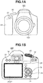
- Figs. 1A and 1B each illustrate an external view of a digital camera 100 serving as an embodiment of an imaging control apparatus to which the present invention is applicable.
- Fig. 1A is a front perspective view of the digital camera 100
- Fig. 1B is a back perspective view of the digital camera 100.
- a display unit 28 is a display portion for displaying images and various kinds of information.
- a lens unit 150 is a lens unit including a lens.
- a shutter button 61 is an operation unit for providing an image capturing instruction.
- a mode selection switch 60 is an operation unit for selecting any of various modes.
- a power switch 72 is an operation member for switching between power-on and power-off of the digital camera 100.
- a cross key 74 is a four-direction key having pressable upper, lower, left, and right portions. It is possible to perform an operation corresponding to the pressed portion of the cross key 74.
- a SET button 75 is a push button to be mainly used for determining a selection item.
- a playback button 79 is an operation button for switching between an image capturing mode and a playback mode. Pressing the playback button 79 in the image capturing mode effects a transition to the playback mode, and can thereby cause the display unit 28 to display the latest image among images recorded in a recording medium 200.
- a MENU button 73 is included in an operation unit 70. The MENU button 73 is provided to display setting items and settings on the display unit 28 when a user performs various kinds of setting of the digital camera 100. In a menu screen, the user can perform time setting and display setting, as well as setting related to communication, and setting of a continuous image capturing velocity (a continuous photographing velocity, and an interval for performing continuous image capturing).
- a touch bar 29 is an operation member provided separately from the shutter button 61, and is disposed at a position where the touch bar 29 can be operated even in a state where the shutter button 61 is pressed.
- the user can grasp a grip portion 90 for holding a camera, with the middle, ring, and little fingers as well as the palm of a hand. Further, the user can place the forefinger on the shutter button 61, and position the thumb at the touch bar 29.
- the shutter button 61 is provided at a location that allows the user to operate the shutter button 61 with the forefinger of the right hand of the user holding the grip portion 90.
- the touch bar 29 is provided at a location that allows the user to perform a touch operation with the thumb of the right hand holding the grip portion 90, while looking through a viewfinder 16.
- the touch bar 29 is provided on the back face of the digital camera 100.
- the back face of the digital camera 100 is a face opposite to the imaging direction.
- the touch bar 29 is provided at a position toward the right side of the viewfinder 16 and toward the left side of the grip portion 90.
- the touch bar 29 is provided in a direction toward the viewfinder 16 with respect to the center of the back face of the digital camera 100 (i.e., on the upper side).
- the touch bar 29 is a device different from the display unit 28, and is disposed at a position higher than the display unit 28 on the back face of the digital camera 100.
- the operation unit 70 includes the shutter button 61, the power switch 72, the cross key 74, the SET button 75, the playback button 79, the touch bar 29, and the MENU button 73.
- the viewfinder 16 is a looking-through-type viewfinder, for confirming a focus and a composition of an object image obtained through the lens unit 150, by observing a display unit (not illustrated) within the viewfinder 16.
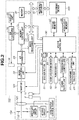
- Fig. 2 is a block diagram illustrating a configuration example of the digital camera 100 according to the present embodiment.
- the lens unit 150 is equipped with a replaceable image capturing lens.
- a lens 103 is typically configured of a plurality lenses, but here, only one lens is illustrated for simplification.
- a communication terminal 6 is provided for the lens unit 150 to communicate with the digital camera 100.
- a communication terminal 10 is provided for the digital camera 100 to communicate with the lens unit 150.
- the lens unit 150 communicates with a system control unit 50 via the communication terminals 6 and 10.
- the lens unit 150 obtains focusing, by controlling an aperture 102 via an aperture drive circuit 2, and displacing the position of the lens 103 via an autofocus (AF) drive circuit 3, by using a lens system control circuit 4 provided inside.
- AF autofocus
- a shutter 101 is a focal plane shutter capable of freely controlling the exposure period of an image capturing unit 22 based on control by the system control unit 50.
- the image capturing unit 22 is an imaging sensor configured of a sensor such as a charge-coupled device (CCD) sensor or complementary metal oxide semiconductor (CMOS) sensor for converting an optical image into an electrical signal.
- An analog-to-digital (A/D) converter 23 converts an analog signal into a digital signal.
- the A/D converter 23 is used to convert an analog signal output from the image capturing unit 22 into a digital signal.
- An image processing unit 24 performs predetermined pixel interpolation, resizing processing such as reduction, and color conversion processing, for data from the A/D converter 23 or data from a memory control unit 15. Further, in the image processing unit 24, predetermined calculation processing is performed using the image data obtained by imaging, and the system control unit 50 performs exposure control and ranging control based on the obtained calculation result. Autofocus (AF) processing, autoexposure (AE) processing, and electronic flash (EF) pre-emission processing in a through-the-lens (TTL) method are thereby performed. Further, in the image processing unit 24, predetermined calculation processing is also performed using the image data obtained by imaging, and automatic white balance (AWB) processing in the TTL method is also performed based on the obtained calculation result.
- AVB automatic white balance
- Output data from the A/D converter 23 is written into a memory 32 via the image processing unit 24 and the memory control unit 15, or directly written into the memory 32 via the memory control unit 15 without going through the image processing unit 24.
- the memory 32 stores image data obtained by the image capturing unit 22 and then converted into digital data by the A/D converter 23, and stores image data to be displayed by the display unit 28.
- the memory 32 has a storage capacity sufficient to store a predetermined number of still images, a moving image, and sound of a predetermined length of time.
- the memory 32 also serves as a memory (video memory) for image display.
- a digital-to-analog (D/A) converter 19 converts data for image display stored in the memory 32 into an analog signal, and supplies the analog signal to the display unit 28. In this way, the image data for display written in the memory 32 is displayed by the display unit 28 via the D/A converter 19.
- the display unit 28 performs display according to the analog signal from the D/A converter 19, on a display device such as a liquid crystal display (LCD).
- the digital signals resulting from the A/D conversion by the A/D converter 23 are accumulated in the memory 32, and the accumulated digital signals are converted into the analog signals by the D/A converter 19.
- These analog signals are then sequentially transferred to the display unit 28 and the display unit within the viewfinder 16 to be displayed.
- Such sequential transfer and display enables the display unit 28 to function as an electronic viewfinder and thus to perform through-image display (live view display).
- a nonvolatile memory 56 is a memory provided as a recording medium that is electrically erasable, recordable, and readable by the system control unit 50.
- EEPROM electrically erasable programmable read only memory
- the nonvolatile memory 56 stores a constant for operation of the system control unit 50, and a program.
- the program here refers to a computer program for executing various flowcharts to be described below in the present embodiment.
- the system control unit 50 includes at least one processor and/or at least one circuit, and controls the entire digital camera 100.
- the system control unit 50 implements each process of the present embodiment, by executing the program recorded in the nonvolatile memory 56 described above.
- a random access memory (RAM) is used for a system memory 52.
- a constant for operation of the system control unit 50, a variable, and a program read out from the nonvolatile memory 56 are loaded into the system memory 52.
- the system control unit 50 also performs display control by controlling components such as the memory 32, the D/A converter 19, and the display unit 28.
- the mode selection switch 60, the shutter button 61, and the operation unit 70 are operation units for inputting various operation instructions into the system control unit 50.
- the mode selection switch 60 changes the operation mode of the system control unit 50 to any of modes including a still-image recording mode, a moving image capturing mode, and the playback mode.
- the still-image recording mode includes a continuous image capturing mode, an automatic image capturing mode, an automatic scene determination mode, a manual mode, and various scene modes for providing image capturing settings by image capturing scene, a program AE mode, and a custom mode.
- the mode selection switch 60 the user can directly switch to any one of these modes included in the menu screen.
- the user may switch to the menu screen with the mode selection switch 60 and then switch to any one of these modes included in the menu screen by using other operation member.
- the moving image capturing mode may include a plurality of modes.
- a first shutter switch 62 is turned on during an operation on the shutter button 61 provided in the digital camera 100, at a half press (an image capturing preparation instruction), and thereby generates a first shutter switch signal SW1.
- the first shutter switch signal SW1 starts operation such as the AF processing, the AE processing, the AWB processing, and the EF pre-flash processing.
- a second shutter switch 64 is turned on at the completion of the operation on the shutter button 61, at a full press (an image capturing instruction), and thereby generates a second shutter switch signal SW2.
- the system control unit 50 starts still-image imaging operation by the image capturing unit 22, i.e., operation of a series of image capturing processes from signal readout from the image capturing unit 22 to writing of image data into the recording medium 200.
- the operation unit 70 includes the function buttons, a touch panel 27, and the touch bar 29, and receives a touch operation on a touch detection surface.
- the touch operation will be described below.
- the function buttons include an end button, a back button, an image feeding button, a jump button, a narrowing-down button, and an attribute change button.
- the MENU button 73 is pressed, the menu screen in which various kinds of setting can be performed is displayed by the display unit 28.
- the user can perform various kinds of setting by intuitively using the menu screen displayed by the display unit 28, the cross key 74, and the SET button 75.
- a power supply control unit 80 includes a battery detecting circuit, a DC-DC converter, and a switch circuit for changing a block to be energized.
- the power supply control unit 80 thereby detects the presence or absence of the attachment of a battery, the type of a battery, and a remaining battery level. Based on the detection results and an instruction of the system control unit 50, the power supply control unit 80 controls the DC-DC converter, thereby supplying a necessary voltage for a necessary period to each of components including the recording medium 200.
- a power supply unit 30 is configured of a primary battery such as an alkaline cell or a lithium battery, or a secondary battery such as a NiCd battery, a NiMH battery, or a Li battery, or an AC adapter.
- a primary battery such as an alkaline cell or a lithium battery
- a secondary battery such as a NiCd battery, a NiMH battery, or a Li battery, or an AC adapter.
- a recording medium interface (I/F) 18 is an interface with the recording medium 200 such as a memory card or a hard disk.
- the recording medium 200 is a nonvolatile recording medium such as a memory card for recording an image in image capturing.
- the recording medium 200 includes a semiconductor memory, an optical disk, or a magnetic disk.
- the touch bar 29 and the touch panel 27 included in the operation unit 70 will be described.
- the touch panel 27 is a touch panel capable of detecting a touch on the display unit 28.
- the touch panel 27 and the display unit 28 can be integrally configured.
- the touch panel 27 is configured to have light transmittance not disturbing display of the display unit 28, and is attached to an upper layer of the display screen of the display unit 28. Subsequently, input coordinates in the touch panel and display coordinates on the display unit 28 are brought into correspondence with each other. This can form a graphical user interface (GUI) that allows the user to perform an operation as if the user is directly operating a screen displayed on the display unit 28.
- GUI graphical user interface
- the system control unit 50 can detect the following operations on the touch panel 27 and the touch bar 29 or states of the touch panel 27 and the touch bar 29.
- the touch bar 29 is not integral with the display screen, but may be integral with the display screen.
- Touch-On When Touch-Down is detected, Touch-On is detected at the same time. After Touch-Down, unless Touch-Up is detected, the detection of Touch-On normally continues. Touch-Move being detected is also a state where Touch-On is detected. Even if Touch-On is detected, Touch-Move is not detected if a touch position has not moved. Upon detection of Touch-Up of all touching fingers or a touching stylus pen, Touch-Off is established.
- Information about these operations and states as well as the position coordinates of a finger or stylus pen touching the touch surface is notified to the system control unit 50 through an internal bus, and the system control unit 50 determines what kind of operation is performed on the touch surface based on the notified information.
- Touch-Move a moving direction of a finger or stylus pen moving on the touch panel can also be determined with respect to each of a vertical component and a horizontal component on the touch panel 27 as well as a horizontal component of the touch bar 29, based on a change of the position coordinates. Further, when Touch-Up is performed after a certain amount of Touch-Move from Touch-Down on the touch surface, this operation can be regarded as drawing of a stroke.
- the flick is such an operation that a finger is quickly moved by some distance while touching the touch surface, and then leaves.
- the flick is an operation of quickly running on the touch surface with a finger as if flipping.
- any of various types may be used, including a resistance film type, a capacitive sensing type, a surface acoustic wave type, an infrared ray type, an electromagnetic induction type, an image recognition type, and an optical sensor type.
- a touch is detected by an approach of a finger or stylus pen to the touch panel 27 or the touch bar 29, or detected by contact of a finger or stylus pen with the touch panel 27 or the touch bar 29, and either method may be adopted.
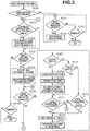
- the system control unit 50 executes the program recorded in the nonvolatile memory 56 by loading the program into the system memory 52, thereby implementing this processing. This processing starts when the digital camera 100 is powered on and the image capturing mode begins.
- step S100 the system control unit 50 determines whether the current image capturing mode is the continuous image capturing mode. If the system control unit 50 determines that the current image capturing mode is the continuous image capturing mode (YES in step S100), the processing proceeds to step S101. If not (NO in step S100), the processing proceeds to step S117.
- step S101 the system control unit 50 determines whether a continuous image capturing velocity S is changed in a menu screen about image capturing.
- the menu screen about image capturing can be displayed by pressing the MENU button 73.
- the continuous image capturing velocity S can be selected from 30 fps, 20 fps, and 10 fps. If the system control unit 50 determines that an operation for changing the continuous image capturing velocity S has been performed (YES in step S101), the processing proceeds to step S102. If not (NO in step S101), the processing proceeds to step S103.
- An interval T between frames in the continuous image capturing is calculated according to the set continuous image capturing velocity S.
- the interval T is longer as the value of the continuous image capturing velocity S is smaller, and the interval T is shorter as the value of the continuous image capturing velocity S is larger.
- step S103 the system control unit 50 determines whether an image capturing instruction is provided.
- the image capturing instruction can be provided by pressing the shutter button 61. If the system control unit 50 determines that the image capturing instruction is provided (YES in step S103), the processing proceeds to step S104. If not (NO in step S103), the processing proceeds to step S116.
- an AE sensor performs light metering, and the image capturing unit 22 performs exposure. Output signals of the respective pixels are sequentially read out, and then each converted into a digital signal by the A/D converter 23.
- the image processing unit 24 performs image processing on output data of each pixel resulting from the digital conversion, and image data generated by this image processing is stored into the memory 32. The processing up to this point is the image capturing of one frame.
- the image data stored in the memory 32 is then stored into the recording medium 200.
- step S105 upon completion of the processing for the image capturing of one frame, the system control unit 50 starts counting the interval T until start of the next image capturing.
- step S106 the system control unit 50 determines whether the image capturing instruction is cancelled. If the shutter button 61 not being pressed is detected (YES in step S106), the processing returns to step S101. If the shutter button 61 is being pressed, the system control unit 50 determines that the user continues the image capturing (NO in step S106), and the processing proceeds to step S107.
- step S107 the system control unit 50 determines whether the touch bar 29 has been touched. In a case where the user touches the touch bar 29 with a finger, the touch is detected. If the system control unit 50 determines that the touch bar 29 has been touched (YES in step S107), the processing proceeds to step S108. If not (NO in step S107), the processing proceeds to step S114.
- step S108 the system control unit 50 changes a touch flag stored in the system memory 52 to NO, and records the touched state of the touch bar 29.
- the touch flag is a flag for indicating whether the touch bar 29 has been touched after the start of the continuous image capturing.
- step S109 the system control unit 50 determines which area of the touch bar 29 is touched by the user.
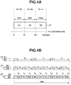
- Fig. 4A illustrates an example of a relationship between an area of the touch bar 29 and the continuous image capturing velocity S.
- the touch bar 29 is divided into three areas and the continuous image capturing velocity S is assigned to each of the areas.
- the system control unit 50 determines which area among these areas is touched.
- the number of the areas is not limited to three.
- the three areas, which are a range of 0 to X1, a range of X1 to X2, and a range of X2 to X3 of coordinates of the touch bar 29, are provided as areas A1, A2, and A3, respectively.
- the continuous image capturing velocities S assigned to the respective areas are velocities ⁇ 1, ⁇ 2, and ⁇ 3.
- ⁇ 3 10 fps
- ⁇ 2 6 fps
- ⁇ 1 3 fps are assigned.
- the continuous image capturing velocity S can be changed according to the touched area, the user can perform the continuous image capturing with flexibility and easy operability according to the state of an object during the continuous image capturing.
- the touch bar 29 capable of detecting a light press is used as an operation member for setting the continuous image capturing velocity S, less vibration is generated than during an operation on a button. Therefore, occurrence of camera shake during an operation is reduced.
- the touch bar 29 is disposed on the back face, not the top face, of the digital camera 100, and thus the optical axis of the lens deviates less easily when a touch operation is made.
- step S112 because the interval T has elapsed by the predetermined time period, the system control unit 50 resets the counting.
- step S113 image capturing of an image capturing frame number N+1 is performed. Similar to step S104, the content of this image capturing is as illustrated in Fig. 5A . When the image capturing is completed, the processing returns to step S105 and the counting of the interval T starts again.
- step S116 the system control unit 50 determines whether an operation for terminating the image capturing mode is performed. For example, when a transition occurs from the image capturing mode to the playback mode, or when the power is turned off, the image capturing mode is terminated. If the system control unit 50 determines that an operation for terminating the image capturing mode is performed (YES in step S116), the image capturing processing is terminated. If not (NO in step S116), the processing returns to step S101.
- Step S117 to step S119 indicate processing in a mode other than the continuous image capturing mode.
- the mode other than the continuous image capturing mode include a normal mode for single image capturing for capturing one frame regardless of the pressing time of the shutter button 61, and the moving image capturing mode.
- step S117 in a manner similar to step S103, the system control unit 50 determines whether an image capturing instruction is provided. If the system control unit 50 determines that an image capturing instruction is provided (YES in step S117), the processing proceeds to step S118. If not (NO in step S117), the processing proceeds to step S119.
- step S118 the system control unit 50 performs image capturing once (one frame) (single image capturing).
- An image capturing method is similar to the method described with reference to step S104. After performing the image capturing once, the shutter button 61 is released from the pressed state, and when the shutter button 61 is pressed again, image capturing is performed. In a case of the moving image mode, recording of a moving image starts in response to an image capturing start instruction, and the recording of the moving image stops in response to an image capturing termination instruction.
- step S119 the system control unit 50 determines whether an operation for terminating the image capturing mode is performed, as in step S116. If the system control unit 50 determines that an operation for terminating the image capturing mode is performed (YES in step S119), the image capturing processing is terminated. If not (NO in step S119), the processing returns to step S117.
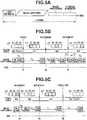
- Fig. 5B illustrates a transition from a state where the touch bar 29 is not touched by the user to a state where the area A1 is touched and subsequently the touch position is moved from the area A2 to the area A3, in the division areas of the touch bar 29 illustrated in Fig. 4A .
- This is an example of a continuous image capturing timing chart of a case where the continuous image capturing velocity S is increased by thus moving the touch position.
- a state from continuous image capturing start to image capturing of the (N+1)th frame is the state where the touch bar 29 is not touched.
- image capturing of a (N+2)th frame is performed after the interval T1 corresponding to 3 fps elapses from the image capturing of the (N+1)th frame.
- the user performs an operation for changing the continuous image capturing velocity S from 3 fps to 6 fps by moving the finger on the touch bar 29 to the area A2 at a time t2 before the interval T1 elapses.
- image capturing of an (N+3)th frame is performed after the interval T2 elapses from the image capturing of the (N+2)th frame.
- the user performs an operation for changing the continuous image capturing velocity S from 6 fps to 10 fps by moving the finger on the touch bar 29 to the area A3.
- the interval is changed to T3 corresponding to 10 fps, but the time t3 is the time that comes after a time period equal to or more than the interval T3 elapses from the image capturing of the (N+4)th frame.
- image capturing of an (N+5)th frame is performed immediately after the change in the touch area at the time t3 is determined.
- the interval before the change is being counted, but the next image capturing is performed at the time when the change operation is performed, even if the interval has not elapsed.
- the user desires to have a continuous image capturing velocity higher than before the change. Therefore, the next image capturing is performed as soon as possible, so that the image capturing intended by the user can be performed.
- Fig. 5C illustrates an example of a continuous image capturing timing chart of a case where the user performs an operation for decreasing the continuous image capturing velocity S, by moving a finger touching the area A3 of the touch bar 29 to the area A2 and then to the area A1.
- the user moves the touch area on the touch bar 29 to the area A2 before the interval T3 elapses.
- the continuous image capturing velocity S is changed to 6 fps assigned to the area A2, and image capturing of an (M+1)th frame is performed after the interval T2 elapses from the image capturing of the Mth frame.
- the user moves the finger to the area A1.
- the continuous image capturing velocity S is changed to 3 fps assigned to the area A1, and image capturing of an (M+3)th frame is performed after the interval T1 elapses from the image capturing of the (M+2)th frame.
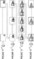
- Figs. 6A to 6D illustrate image capturing of an approaching train, as an example.
- the user desires to capture an image at the timing when the train, which is a main object, comes forward, the user starts the continuous image capturing by pressing the shutter button 61 before the train comes.
- the continuous image capturing may not be performed at high velocity ( Fig. 6A ). Therefore, the user performs the continuous image capturing at 3 fps, by touching the area A1 of the touch bar 29.
- the user moves the finger on the area A1 of the touch bar 29 to the area A2, thereby increasing the continuous image capturing velocity to 6 fps ( Fig. 6B ).
- the user moves the finger to the area A3, thereby increasing the continuous image capturing velocity to 10 fps ( Fig. 6C ).
- the user returns the finger to the area A2, thereby decreasing the continuous image capturing velocity to 6 fps ( Fig. 6D ). The user can thus change the continuous image capturing velocity.
- the continuous image capturing velocity is decreased to avoid excessive image capturing.
- the continuous image capturing is performed for capturing the same object. If the user performs an operation for changing the velocity by opening the menu screen in the middle of the image capturing, the user cannot perform the image capturing while performing such an operation. However, according to this use case, the user only needs to change the touch area during the continuous image capturing and therefore, the user can continue the image capturing for the same object, without stopping the continuous image capturing.
- FIG. 7A illustrates an operation for moving the finger from left to right (from the area A2 to the area A3), thereby increasing the continuous image capturing velocity S.
- Fig. 7B illustrates an operation for moving the finger from right to left (from the area A3 to the area A2), thereby decreasing the continuous image capturing velocity S.
- Fig. 7A illustrates an operation for moving the finger from left to right (from the area A2 to the area A3), thereby increasing the continuous image capturing velocity S.
- Fig. 7B illustrates an operation for moving the finger from right to left (from the area A3 to the area A2), thereby decreasing the continuous image capturing velocity S.
- the continuous image capturing velocity S immediately before is maintained and thus, the continuous image capturing velocity S is not unintentionally changed.
- the continuous image capturing velocity S is not changed.
- the touch bar 29 is used as a member for changing the continuous image capturing velocity S during the continuous image capturing.
- the member for changing the continuous image capturing velocity S is not limited to the touch bar 29 and may be any type of member as long as the member is a touch operation member.
- the touch panel 27 may also be used in place of the touch bar 29.
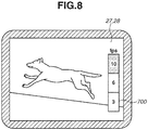
- Fig. 8 illustrates an example of a case where the continuous image capturing velocity S is changed using the touch panel 27.
- a bar 700 is displayed on the display unit 28 integral with the touch panel 27.
- the continuous image capturing velocities S are assigned to portions that the user can operate while pressing the shutter button 61, with another finger.
- the continuous image capturing velocity S may be changed according to which area of the bar 700 displayed during the continuous image capturing is touched.
- the user can change the interval of the continuous image capturing during the continuous image capturing, with good operability.
- the image capturing is performed at the maximum velocity among the set continuous image capturing velocities, whereas for an image capturing period during which the touch bar 29 is touched, the interval for the continuous image capturing is decided according to the touch position of the touch bar 29.
- the user can decide the interval of the continuous image capturing according to the state of an object with good operability and can perform image capturing with flexibility during the continuous image capturing.
- the interval T is changed according to the set continuous image capturing velocity S, whereby the time interval for image capturing is changed.
- a flag to an image captured at the time when the interval according to the continuous image capturing velocity S has elapsed, and keep only the image with the flag among images recorded in the recording medium 200 after the image capturing, deleting the rest of the images.
- only the image with the flag may be stored from the memory 32 into the recording medium 200, and an image with no flag may be deleted. Only the image with the flag may be saved from the recording medium 200 into an external media.
- This interval is not changed in setting of any of the continuous image capturing velocities S.
- the flag is attached to an image at an interval corresponding to the value of this change.
- Flag is attached to the first image captured after the interval T1, in a case where the area A1 is touched, or after the interval T2, in a case where the area A2 is touched, elapses from an image capturing, and this image is recorded into the recording medium 200.
- this image is recorded into the recording medium 200.
- the flag in a case where the area A1 is touched, the flag is attached to an (N+3)th image after the interval T1 elapses from an Nth image, to an (N+6)th image after the interval T1 further elapses, and to an (N+9)th image after the interval T1 further elapses.
- the flag is attached to an (N+2)th image that is a first image after the interval T2 elapses from the Nth image. Subsequently, the flag is similarly attached to an (N+4)th image, an (N+6)th image, and an (N+8)th image, and these images are each recorded.
- the continuous image capturing velocity has been described to be decreased according to the touch to the touch bar 29, but it may be increased instead.
- the various kinds of control described above to be performed by the system control unit 50 may be performed by a single piece of hardware, or a plurality of pieces of hardware may share the processing to control the entire apparatus.
- the present invention is not limited to this case and is applicable to any type of imaging control apparatus if the apparatus can control continuous image capturing.
- the present invention is applicable to apparatuses including a mobile phone terminal, a portable image viewer, a printer apparatus with a viewfinder, a digital photo frame, a music player, a game console, and an electronic-book reader.
- operability in performing continuous image capturing can be improved.
- Embodiment(s) of the present invention can also be realized by a computer of a system or apparatus that reads out and executes computer executable instructions (e.g., one or more programs) recorded on a storage medium (which may also be referred to more fully as a 'non-transitory computer-readable storage medium') to perform the functions of one or more of the above-described embodiment(s) and/or that includes one or more circuits (e.g., application specific integrated circuit (ASIC)) for performing the functions of one or more of the above-described embodiment(s), and by a method performed by the computer of the system or apparatus by, for example, reading out and executing the computer executable instructions from the storage medium to perform the functions of one or more of the above-described embodiment(s) and/or controlling the one or more circuits to perform the functions of one or more of the above-described embodiment(s).
- computer executable instructions e.g., one or more programs
- a storage medium which may also be referred to more fully as
- the computer may comprise one or more processors (e.g., central processing unit (CPU), micro processing unit (MPU)) and may include a network of separate computers or separate processors to read out and execute the computer executable instructions.
- the computer executable instructions may be provided to the computer, for example, from a network or the storage medium.
- the storage medium may include, for example, one or more of a hard disk, a random-access memory (RAM), a read only memory (ROM), a storage of distributed computing systems, an optical disk (such as a compact disc (CD), digital versatile disc (DVD), or Blu-ray Disc (BD)TM), a flash memory device, a memory card, and the like.
Landscapes
- Engineering & Computer Science (AREA)
- Multimedia (AREA)
- Signal Processing (AREA)
- Human Computer Interaction (AREA)
- Computing Systems (AREA)
- Theoretical Computer Science (AREA)
- Studio Devices (AREA)
- Exposure Control For Cameras (AREA)
- Details Of Cameras Including Film Mechanisms (AREA)
- Camera Bodies And Camera Details Or Accessories (AREA)
Applications Claiming Priority (1)
| Application Number | Priority Date | Filing Date | Title |
|---|---|---|---|
| JP2017215914A JP2019086701A (ja) | 2017-11-08 | 2017-11-08 | 撮像制御装置およびその制御方法 |
Publications (1)
| Publication Number | Publication Date |
|---|---|
| EP3484142A1 true EP3484142A1 (en) | 2019-05-15 |
Family
ID=64270611
Family Applications (1)
| Application Number | Title | Priority Date | Filing Date |
|---|---|---|---|
| EP18204419.8A Withdrawn EP3484142A1 (en) | 2017-11-08 | 2018-11-05 | Imaging control apparatus, control method therefor, program, and recording medium |
Country Status (5)
| Country | Link |
|---|---|
| US (1) | US10924671B2 (enExample) |
| EP (1) | EP3484142A1 (enExample) |
| JP (1) | JP2019086701A (enExample) |
| KR (1) | KR20190052634A (enExample) |
| CN (1) | CN109756669A (enExample) |
Families Citing this family (2)
| Publication number | Priority date | Publication date | Assignee | Title |
|---|---|---|---|---|
| US11283990B2 (en) * | 2017-04-18 | 2022-03-22 | Sony Corporation | Display control device, imaging device, and display control method |
| US11140292B1 (en) * | 2019-09-30 | 2021-10-05 | Gopro, Inc. | Image capture device for generating time-lapse videos |
Citations (5)
| Publication number | Priority date | Publication date | Assignee | Title |
|---|---|---|---|---|
| JP2002148693A (ja) | 2000-11-06 | 2002-05-22 | Canon Inc | カメラ |
| US20030146981A1 (en) * | 2002-02-04 | 2003-08-07 | Bean Heather N. | Video camera selector device |
| JP2010141582A (ja) | 2008-12-11 | 2010-06-24 | Olympus Imaging Corp | カメラ、連写タイミング設定方法および連写タイミング設定用プログラム |
| US20100295970A1 (en) * | 2009-05-20 | 2010-11-25 | Toshihiko Suzuki | Imaging apparatus and reproducing apparatus |
| US20160269674A1 (en) * | 2015-03-09 | 2016-09-15 | Microsoft Technology Licensing, Llc | Dynamic Video Capture Rate Control |
Family Cites Families (18)
| Publication number | Priority date | Publication date | Assignee | Title |
|---|---|---|---|---|
| US6424806B1 (en) | 1998-12-03 | 2002-07-23 | Fuji Photo Film Co., Ltd. | Camera having interlock preventing simultaneous use of electronic zoom and panoramic format |
| JP2006221036A (ja) | 2005-02-14 | 2006-08-24 | Fuji Photo Film Co Ltd | カメラ |
| JP5168837B2 (ja) * | 2006-07-27 | 2013-03-27 | ソニー株式会社 | 画像処理装置、画像処理方法およびプログラム |
| JP4254836B2 (ja) | 2006-10-10 | 2009-04-15 | ソニー株式会社 | 撮像装置 |
| JP2009025643A (ja) * | 2007-07-20 | 2009-02-05 | Olympus Corp | カメラ |
| JP2010087778A (ja) * | 2008-09-30 | 2010-04-15 | Casio Computer Co Ltd | 撮像装置、変速撮像方法、及びプログラム |
| CN101626500B (zh) | 2009-07-31 | 2011-07-27 | 北京大学深圳研究生院 | 一种视频帧率控制方法及装置 |
| JP5127792B2 (ja) * | 2009-08-18 | 2013-01-23 | キヤノン株式会社 | 情報処理装置、その制御方法、プログラム及び記録媒体 |
| JP5306266B2 (ja) * | 2010-03-15 | 2013-10-02 | キヤノン株式会社 | 撮像装置及びその制御方法 |
| JP5921121B2 (ja) * | 2011-09-09 | 2016-05-24 | キヤノン株式会社 | 撮像装置、その制御方法及びプログラム並びに記録媒体 |
| JP2013101313A (ja) | 2011-10-21 | 2013-05-23 | Panasonic Corp | カメラシステム、カメラ本体 |
| JP5613187B2 (ja) * | 2012-01-27 | 2014-10-22 | オリンパスイメージング株式会社 | 撮像装置、撮像装置の制御方法、及び、撮像装置の制御をコンピュータに行わせるためのコードを備える持続性コンピュータ可読媒体 |
| TWI519155B (zh) * | 2012-02-24 | 2016-01-21 | 宏達國際電子股份有限公司 | 影像連續拍攝方法與相關影像擷取系統 |
| WO2013153713A1 (ja) | 2012-04-10 | 2013-10-17 | 富士フイルム株式会社 | 撮像装置および撮影方法 |
| JP5668803B2 (ja) * | 2013-07-11 | 2015-02-12 | カシオ計算機株式会社 | 撮影装置及び撮影方法 |
| CN103970272B (zh) | 2014-04-10 | 2018-04-27 | 北京智谷睿拓技术服务有限公司 | 交互方法、装置及用户设备 |
| US20160309063A1 (en) | 2015-04-17 | 2016-10-20 | mPerpetuo, Inc. | Digital Camera Accessory Providing a Secondary Image Capture Device ("SICD") |
| KR102400998B1 (ko) | 2015-07-15 | 2022-05-23 | 삼성전자주식회사 | 사용자의 제스쳐를 이용하여 기능을 제어하는 방법 및 촬영 장치. |
-
2017
- 2017-11-08 JP JP2017215914A patent/JP2019086701A/ja active Pending
-
2018
- 2018-10-30 US US16/175,576 patent/US10924671B2/en active Active
- 2018-11-05 EP EP18204419.8A patent/EP3484142A1/en not_active Withdrawn
- 2018-11-07 KR KR1020180135521A patent/KR20190052634A/ko not_active Abandoned
- 2018-11-07 CN CN201811317489.XA patent/CN109756669A/zh active Pending
Patent Citations (5)
| Publication number | Priority date | Publication date | Assignee | Title |
|---|---|---|---|---|
| JP2002148693A (ja) | 2000-11-06 | 2002-05-22 | Canon Inc | カメラ |
| US20030146981A1 (en) * | 2002-02-04 | 2003-08-07 | Bean Heather N. | Video camera selector device |
| JP2010141582A (ja) | 2008-12-11 | 2010-06-24 | Olympus Imaging Corp | カメラ、連写タイミング設定方法および連写タイミング設定用プログラム |
| US20100295970A1 (en) * | 2009-05-20 | 2010-11-25 | Toshihiko Suzuki | Imaging apparatus and reproducing apparatus |
| US20160269674A1 (en) * | 2015-03-09 | 2016-09-15 | Microsoft Technology Licensing, Llc | Dynamic Video Capture Rate Control |
Also Published As
| Publication number | Publication date |
|---|---|
| US20190141244A1 (en) | 2019-05-09 |
| US10924671B2 (en) | 2021-02-16 |
| JP2019086701A (ja) | 2019-06-06 |
| CN109756669A (zh) | 2019-05-14 |
| KR20190052634A (ko) | 2019-05-16 |
Similar Documents
| Publication | Publication Date | Title |
|---|---|---|
| US10623647B2 (en) | Image capturing apparatus and control method for changing a setting based on a touch operation on a display | |
| RU2466447C1 (ru) | Устройство захвата изображения и способ управления им | |
| US20210173536A1 (en) | Electronic apparatus and control method thereof | |
| US10216313B2 (en) | Electronic apparatus and control method of the same | |
| US11082608B2 (en) | Electronic apparatus, method, and storage medium | |
| US10212335B2 (en) | Electronic apparatus and control method therefor | |
| US10523862B2 (en) | Electronic device, method, and medium for touch movement control | |
| US10313580B2 (en) | Electronic apparatus, control method therefor, and storage medium | |
| US9992405B2 (en) | Image capture control apparatus and control method of the same | |
| US11240419B2 (en) | Electronic device that can execute function in accordance with line of sight of user, method of controlling electronic device, and non-transitory computer readable medium | |
| US10120496B2 (en) | Display control apparatus and control method thereof | |
| US12439155B2 (en) | Display control apparatus and control method | |
| US10924671B2 (en) | Imaging control apparatus with improved operability in performing continuous image capturing by using a shutter button and a touch bar, control method therefor, and recording | |
| US9088762B2 (en) | Image capturing apparatus and control method thereof | |
| JP5575290B2 (ja) | 撮像装置及びその制御方法 | |
| US10389945B2 (en) | Imaging control apparatus, control method for the same, and storage medium | |
| US11418715B2 (en) | Display control apparatus and control method therefor | |
| US11169684B2 (en) | Display control apparatuses, control methods therefor, and computer readable storage medium | |
| US12147629B2 (en) | Electronic apparatus, control method for electronic apparatus, and storage medium | |
| US12501143B2 (en) | Image capture apparatus, control method for the same, and non-transitory computer-readable storage medium | |
| JP5863418B2 (ja) | 撮像装置及びその制御方法 | |
| JP2017085465A (ja) | 撮像装置、その制御方法、および制御プログラム |
Legal Events
| Date | Code | Title | Description |
|---|---|---|---|
| PUAI | Public reference made under article 153(3) epc to a published international application that has entered the european phase |
Free format text: ORIGINAL CODE: 0009012 |
|
| STAA | Information on the status of an ep patent application or granted ep patent |
Free format text: STATUS: THE APPLICATION HAS BEEN PUBLISHED |
|
| AK | Designated contracting states |
Kind code of ref document: A1 Designated state(s): AL AT BE BG CH CY CZ DE DK EE ES FI FR GB GR HR HU IE IS IT LI LT LU LV MC MK MT NL NO PL PT RO RS SE SI SK SM TR |
|
| AX | Request for extension of the european patent |
Extension state: BA ME |
|
| STAA | Information on the status of an ep patent application or granted ep patent |
Free format text: STATUS: REQUEST FOR EXAMINATION WAS MADE |
|
| 17P | Request for examination filed |
Effective date: 20191115 |
|
| RBV | Designated contracting states (corrected) |
Designated state(s): AL AT BE BG CH CY CZ DE DK EE ES FI FR GB GR HR HU IE IS IT LI LT LU LV MC MK MT NL NO PL PT RO RS SE SI SK SM TR |
|
| STAA | Information on the status of an ep patent application or granted ep patent |
Free format text: STATUS: EXAMINATION IS IN PROGRESS |
|
| 17Q | First examination report despatched |
Effective date: 20210311 |
|
| STAA | Information on the status of an ep patent application or granted ep patent |
Free format text: STATUS: THE APPLICATION HAS BEEN WITHDRAWN |
|
| 18W | Application withdrawn |
Effective date: 20211027 |