EP3483661A1 - Outil d'actionnement d'un correcteur équipant un objet portable de petites dimensions tel qu'une pièce d'horlogerie - Google Patents
Outil d'actionnement d'un correcteur équipant un objet portable de petites dimensions tel qu'une pièce d'horlogerie Download PDFInfo
- Publication number
- EP3483661A1 EP3483661A1 EP17200902.9A EP17200902A EP3483661A1 EP 3483661 A1 EP3483661 A1 EP 3483661A1 EP 17200902 A EP17200902 A EP 17200902A EP 3483661 A1 EP3483661 A1 EP 3483661A1
- Authority
- EP
- European Patent Office
- Prior art keywords
- actuating
- tool
- actuating tool
- portable object
- corrective
- Prior art date
- Legal status (The legal status is an assumption and is not a legal conclusion. Google has not performed a legal analysis and makes no representation as to the accuracy of the status listed.)
- Granted
Links
Images


Classifications
-
- G—PHYSICS
- G04—HOROLOGY
- G04B—MECHANICALLY-DRIVEN CLOCKS OR WATCHES; MECHANICAL PARTS OF CLOCKS OR WATCHES IN GENERAL; TIME PIECES USING THE POSITION OF THE SUN, MOON OR STARS
- G04B3/00—Normal winding of clockworks by hand or mechanically; Winding up several mainsprings or driving weights simultaneously
- G04B3/02—Removably-mounted keys or the like
-
- G—PHYSICS
- G04—HOROLOGY
- G04D—APPARATUS OR TOOLS SPECIALLY DESIGNED FOR MAKING OR MAINTAINING CLOCKS OR WATCHES
- G04D1/00—Gripping, holding, or supporting devices
- G04D1/02—Tweezers; Vice clamps or other special hand tools for watchmakers
- G04D1/027—Hand tools for gripping or holding by magnetic means
-
- G—PHYSICS
- G04—HOROLOGY
- G04B—MECHANICALLY-DRIVEN CLOCKS OR WATCHES; MECHANICAL PARTS OF CLOCKS OR WATCHES IN GENERAL; TIME PIECES USING THE POSITION OF THE SUN, MOON OR STARS
- G04B3/00—Normal winding of clockworks by hand or mechanically; Winding up several mainsprings or driving weights simultaneously
- G04B3/04—Rigidly-mounted keys, knobs or crowns
- G04B3/048—Operation exclusively by axial movement of a push-button, e.g. for chronographs
-
- G—PHYSICS
- G04—HOROLOGY
- G04G—ELECTRONIC TIME-PIECES
- G04G17/00—Structural details; Housings
- G04G17/02—Component assemblies
-
- G—PHYSICS
- G04—HOROLOGY
- G04G—ELECTRONIC TIME-PIECES
- G04G5/00—Setting, i.e. correcting or changing, the time-indication
- G04G5/04—Setting, i.e. correcting or changing, the time-indication by setting each of the displayed values, e.g. date, hour, independently
Definitions
- the present invention relates to a tool for actuating a corrector equipping a portable object of small dimensions such as a timepiece.
- the invention relates more particularly to a tool for actuating a small push button also called corrector that commonly equips portable objects such as wristwatches with major complications or smart phones.
- Some watches especially so-called high-complexity watches, offer their users such a large number of functions that it is not possible to correct them all with the help of a single winding and correction crown. It is for this reason that such watches include additional control means such as pushbuttons.
- pushbuttons of different types among which there are miniature pushbuttons that are typically embedded in the middle part of the watch and that is usually operated by means of a pointed instrument.
- These miniature pushbuttons conventionally comprise a bushing driven, glued or screwed into an opening made in the middle part of the watch, and a cylindrical control rod able to slide freely in the socket.
- the sleeve comprises, on the outside of the watch case, a first cylindrical passage adapted to the dimensions of a first portion of the control rod, and the inner side of the watch case, a second cylindrical passage arranged in the extension of the first cylindrical passage and whose inner diameter, adapted to the dimensions of a second portion of the control rod is smaller than that of the first cylindrical passage.
- a seal housed in a groove on a perimeter of the first portion of the control rod ensures the seal between the control rod and the sleeve.
- Such a push button also comprises a coil spring which compresses when the user presses the miniature push button, and whose restoring force returns the control rod to the rest position when the user releases the pressure on the button. -poussoir.
- Push buttons of the type described above have very small dimensions. Such pushbuttons thus save space. In addition, they do not protrude from the middle part and therefore do not risk being actuated involuntarily. The correction operations are done by pushing the control rod into the socket against the return force of the coil spring by means of a pointed instrument such as a pen for example. This last point is problematic. Indeed, as mentioned above, such push buttons are most often equipped wristwatches with major complications. These are extremely expensive watches whose boxes are often made using precious materials. However, the risks of hurting the watch case and altering its appearance when handling a sharp instrument are important, which has become difficult to accept. Of course, there is always the possibility to return the watch in the workshop so that it is repolished, but it is not very convenient.
- Push buttons of the type described above are also found on other small portable objects such as smart phones and their actuation is often used to reset the electronic circuits of the phone.
- the present invention aims to remedy the aforementioned problems as well as others by providing a tool that can be used by watchmakers, but primarily intended for watch wearers and to operate small pushbuttons still called correctors without the risk of injuring the middle part of the watch case.
- the tool according to the invention can also be used to actuate the correctors that equip for example smart phones and which are used for example to perform the reset of the operating system of the phone.
- the present invention relates to a tool for actuating a corrective push button fitted to a portable object of small dimensions, this actuation tool comprising a body which extends between a rear end which defines a gripping zone. of the actuating tool and a front end which defines an actuating zone of the actuating tool, at least the front end of the actuating tool being magnetized.
- a magnetic bar is arranged in the front end of the actuating tool.
- the body of the actuating tool is made by means of a magnetic material.
- the invention also relates to a portable object of small dimensions such as a timepiece, this portable object comprising a middle part in an opening of which is fixed a corrective pushbutton, at least one element of the push-button corrector or at the at least one zone of the middle part immediately surrounding the corrective push-button being made of a ferromagnetic material or a magnetic material.
- the invention also relates to an assembly comprising a tool for actuating a corrective pushbutton fitted to a portable object small size, this actuating tool comprising a body which extends between a rear end which defines a gripping area of the actuating tool and a front end which defines an actuating zone of the tool of actuation, at least the front end of the actuating tool being magnetized, the portable object comprising a middle part in an opening of which is fixed a push-type corrector, at least one element of the corrector or at least one zone the middle part of the portable object that immediately surrounds the corrector being made of a ferromagnetic material or a magnetic material whose first magnetic polarity is opposite to a second magnetic polarity of the magnetic actuation tool.
- the invention also relates to an assembly comprising a tool for actuating a push-type corrector equipping a portable object of small dimensions, this actuating tool comprising a body which extends between a rear end which defines a gripping zone. of the actuating tool and a front end which defines an actuating zone of the actuating tool, at least the front end of the actuating tool being made of a ferromagnetic material, the portable object comprising a middle part in an opening of which is fixed a push-type corrector, at least one element of the corrector or at least one area of the middle part immediately surrounding the corrector being made of a magnetic material.
- the present invention provides an actuating tool which, under the effect of the magnetic attraction force exerted on it by the corrector or the environment close to the corrector, will spontaneously come into contact with the corrector. in the center of the latter, so that it is then left to the user to exert a thrust on the actuating tool to be able to actuate the corrector.
- the risks that the actuating tool skids on the middle of the portable object equipped with the corrector and scratches it when the user wants to operate the corrector are weak or nonexistent.
- the present invention proceeds from the general inventive idea of providing an actuating tool for actuating a push button corrector type embedded in the middle part of a portable object such as a wristwatch complications or a smart phone without the risk of hurting the middle part of the portable object which, especially in the case of wristwatches, is very often made of a precious material.
- the present invention teaches the use of an actuating tool which, by magnetic attraction exerted by the corrector or a portion of the middle part close to the corrector, guides the tip of the tool in the center of the corrector. Once the actuator tool centered on the corrector, it is not enough for the user to exert a push on the corrector to enter a command. Any risk of seeing the end of the actuating tool slide on the middle and injure it is thus removed.
- the figure 1 is a perspective view of an embodiment of a push button corrector type whose operation can be performed by means of an actuating tool according to the invention.
- a corrective push-button is given purely by way of illustration and is in no way limiting only.
- it is a conventional type of corrective push-button whose structure at most only needs to be modified as regards the choice of the material in which are made its components, while in some embodiments of the invention, the structure of the corrective pushbutton remains unchanged.
- a push-button corrector type conventionally comprises a socket 2 for example driven or glued into an opening 4 made in a middle 6 of a portable object, for example a wristwatch which the middle part is made of a precious material or a smart phone.
- a cylindrical control rod 8 is slidable in the sleeve 2.
- the sleeve 2 comprises for this purpose a first cylindrical passage 10a which opens on the outside of the middle part 6 of the portable object and which is adapted to the dimensions of a first portion 12a of the control rod 8.
- the sleeve 2 On the inner side of the middle part 6, the sleeve 2 comprises a second cylindrical passage 10b arranged in the extending the first cylindrical passage 10a and defining a shoulder 14 inside the sleeve 2.
- the inner diameter of the second cylindrical passage 10b, adapted to the dimensions of a second portion 12b of the control rod 8, is less than that of the first cylindrical passage 10a.
- a seal 16 housed in a groove formed on a perimeter of the first portion 12a of the control rod 8 ensures the seal between the control rod 8 and the sleeve 2.
- a corrective pushbutton 1 comprises also a coil spring 18 which compresses when the user presses the corrector push button 1, and whose restoring force returns the control rod 8 to the rest position when the user releases the pressure on the push-button corrector 1.
- the coil spring 18 is in abutment against a washer 20 fixedly mounted on the first portion 12a of the control rod 8 at one end, and against the shoulder 14 at the other end.
- Push buttons of the type described above have very small dimensions. They therefore save space. In addition, they do not protrude from the middle part and therefore do not risk being actuated involuntarily. Such push buttons frequently equip high-end watches said to complications. Correction operations are done using a sharp instrument such as a pen for example. This last point, however, poses a problem. In fact, complicated wristwatches are expensive watches whose watch cases are very often made using precious materials. However, the risks of hurting the watch case and altering its appearance when handling a sharp instrument are important, which has become difficult to accept.
- the present invention teaches that at least one of the components of the corrective push-button 1 detailed above is made by means of a ferromagnetic material, that is to say a material that is magnetizable ( see Figures 2B and 2C ). It may be, for purely illustrative and non-limiting purposes, the sleeve 2, or even the rod control 8, or both of these components simultaneously. In the case where it is for example the control rod 8 which is made of a ferromagnetic material, the middle 6 of the portable object will preferably be made of a non-magnetizable material.
- At least a portion 22 of the middle part 6 of the portable object located in the immediate vicinity of the corrective push-button 1 is also made of a ferromagnetic material.
- this portion 22 of the middle part 6 will be arranged with a circular symmetry around the corrector push button 1.
- It may be, for example, a ring 24 arranged concentrically around the socket 2 (see Figures 3B and 3C ).
- It may also be, for example, two studs 26a and 26b made of a ferromagnetic material and preferably arranged diametrically opposite with respect to the center 28 of the corrector push button 1 materialized by the control rod 8 (see Figures 4B and 4C ).
- none of the components of the corrector pushbutton 1 is made of a ferromagnetic material, only a portion 22 of the middle part 6 then being made of such a ferromagnetic material.
- immediate proximity is meant that the portion 22 of the caseband 6 is arranged sufficiently close to the correcting pushbutton 1 so that, when the user approaches the actuating tool 30 according to the invention of the corrective pushbutton 1, the magnetic attraction exerted on this actuating tool 30 guides this tool 30 towards the control rod 8, that is to say toward the center 28 of the corrective push-button 1. It is then sufficient for the user to exert a thrust on the actuating tool 30 to be able to actuate the corrective push-button 1.
- the actuating tool 30 comprises a body 32 which extends between a rear end 32a which defines a gripping zone of this tool 30, and a front end 32b which defines an actuating zone of this tool 30.
- the actuating tool 30 is made entirely of a magnetic material and is attracted by the ferromagnetic material in which is made at least a portion 22 of the middle part and / or at least one of the components of the corrective push-button 1.
- this actuating tool 30 is irresistibly attracted by the corrector pushbutton 1, towards the center 28 of the latter.
- a magnet bar 34 is disposed in a housing 36 formed in the front end 32b of the body 32 which defines the operating zone of the actuating tool 30.
- the embodiment described above is particularly advantageous because, as it involves a magnet bar 34 only on the side of the actuating tool 30, and that the middle part 6 and / or the corrective push-button 1 include only a ferromagnetic material, it is not necessary to worry about the polarity of the magnet to ensure the magnetic attraction of the actuating tool 30 by the portable object.
- Another embodiment of the invention consists in producing all or part of the actuating tool in a ferromagnetic material and in disposing a bipolar magnet in the portable object.
- the front end 32b which defines the operating zone of the actuating tool 30 is made of a ferromagnetic material, and that at least one component of the corrective pushbutton 1, for example the control rod 8 or the sleeve 2, is made of a magnetic material.
- at least one and, preferably, two discrete bipolar magnets 38a and 38b preferably diametrically opposite to the center 28 of the corrector pushbutton 1.
- the discrete bipolar magnets 38a, 38b can be replaced by an annular magnet 40 arranged around the bushing 2 of the correcting push-button 1, at a short distance from the latter ( Figures 5B and 5C ).
- a bipolar magnet 38, 40 is only involved on the side of the portable object, so that it is not necessary to be concerned with the polarity of the magnet to guarantee the magnetic attraction. of the actuating tool 30 by the portable object.
- a bipolar magnet 42 is arranged in the front end 32b of the operating zone of the actuating tool 30 ( Figure 6A ), and at least one component of the corrector push-button 1 and / or at least one portion 22 of the caseband 6 is made of a magnetic material ( Figures 6B and 6C ). It should be understood that, in this embodiment, it must be ensured that the magnetic polarity of the actuating tool is opposite to the magnetic polarity of the corrective push-button 1.
Landscapes
- Physics & Mathematics (AREA)
- General Physics & Mathematics (AREA)
- Electric Clocks (AREA)
- Magnetic Treatment Devices (AREA)
Abstract
Description
- La présente invention concerne un outil d'actionnement d'un correcteur équipant un objet portable de petites dimensions tel qu'une pièce d'horlogerie. L'invention concerne plus particulièrement un outil permettant d'actionner un bouton-poussoir de petites dimensions encore appelé correcteur qui équipe couramment des objets portables tels que des montres-bracelets à grandes complications ou bien des téléphones intelligents.
- Certaines montres, en particulier les montres dites à grandes complications, offrent à leurs utilisateurs un nombre si élevé de fonctions qu'il n'est pas possible de les corriger toutes à l'aide d'une unique couronne de remontage et de correction. C'est pour cette raison que de telles montres comprennent des moyens de commande supplémentaires tels que des boutons-poussoirs. Il existe des boutons-poussoirs de différents types parmi lesquels on trouve des boutons-poussoirs miniatures qui sont typiquement noyés dans la carrure de la montre et que l'on actionne habituellement au moyen d'un instrument pointu. Ces boutons-poussoirs miniatures comprennent classiquement une douille chassée, collée ou vissée dans une ouverture pratiquée dans la carrure de la montre, et une tige de commande cylindrique apte à coulisser librement dans la douille. La douille comprend, du côté extérieur de la boîte de la montre, un premier passage cylindrique adapté aux dimensions d'une première portion de la tige de commande, et du côté intérieur de la boîte de la montre, un second passage cylindrique agencé dans le prolongement du premier passage cylindrique et dont le diamètre intérieur, adapté aux dimensions d'une seconde portion de la tige de commande, est inférieur à celui du premier passage cylindrique. Une garniture d'étanchéité logée dans une saignée ménagée sur un périmètre de la première portion de la tige de commande permet de garantir l'étanchéité entre la tige de commande et la douille. Un tel bouton-poussoir comprend également un ressort hélicoïdal qui se comprime lorsque l'utilisateur appuie sur le bouton-poussoir miniature, et dont la force de rappel ramène la tige de commande en position de repos lorsque l'utilisateur relâche la pression sur le bouton-poussoir.
- Des boutons-poussoirs du type décrit ci-dessus ont des dimensions très réduites. De tels boutons-poussoirs permettent donc de gagner de la place. En outre, ils ne font pas saillie de la carrure et ne risquent donc pas d'être actionnés involontairement. Les opérations de correction se font en enfonçant la tige de commande dans la douille à l'encontre de la force de rappel du ressort hélicoïdal au moyen d'un instrument pointu tel qu'un stylo par exemple. Ce dernier point pose problème. En effet, comme mentionné ci-avant, de tels boutons-poussoirs équipent le plus souvent des montres-bracelets à grandes complications. Il s'agit de montres extrêmement onéreuses dont les boîtes sont très souvent réalisées à l'aide de matériaux précieux. Or, les risques de blesser la boîte de la montre et d'altérer son aspect esthétique lorsqu'on manipule un instrument pointu sont importants, ce qui est devenu difficilement acceptable. Bien entendu, il existe toujours la possibilité de retourner la montre en atelier afin qu'elle y soit repolie, mais cela n'est pas très commode.
- Des boutons-poussoirs du type décrit ci-dessus se retrouvent également sur d'autres objets portables de petites dimensions tels que des téléphones intelligents et leur actionnement sert souvent à remettre à zéro les circuits électroniques du téléphone.
- La présente invention a pour but de remédier aux problèmes susmentionnés ainsi qu'à d'autres encore en procurant un outil pouvant être utilisé par les horlogers, mais avant tout destiné aux porteurs de montres et permettant d'actionner de petits boutons-poussoirs encore appelés correcteurs sans risque de blesser la carrure de la boîte de montre. L'outil selon l'invention peut également être utilisé pour actionner les correcteurs qui équipent par exemple des téléphones intelligents et qui servent par exemple à effectuer la remise à zéro du système d'exploitation du téléphone.
- A cet effet, la présente invention concerne un outil d'actionnement d'un bouton-poussoir correcteur équipant un objet portable de petites dimensions, cet outil d'actionnement comprenant un corps qui s'étend entre une extrémité arrière qui définit une zone de préhension de l'outil d'actionnement et une extrémité avant qui définit une zone d'actionnement de l'outil d'actionnement, au moins l'extrémité avant de l'outil d'actionnement étant aimantée.
- Selon un mode de réalisation de l'invention, un barreau aimanté est agencé dans l'extrémité avant de l'outil d'actionnement.
- Selon un autre mode de réalisation, le corps de l'outil d'actionnement est réalisé au moyen d'un matériau magnétique.
- L'invention concerne également un objet portable de petites dimensions tel qu'une pièce d'horlogerie, cet objet portable comprenant une carrure dans une ouverture de laquelle est fixé un bouton-poussoir correcteur, au moins un élément du bouton-poussoir correcteur ou au moins une zone de la carrure qui entoure immédiatement le bouton-poussoir correcteur étant réalisé en un matériau ferromagnétique ou en un matériau magnétique.
- L'invention concerne également un ensemble comprenant un outil d'actionnement d'un bouton-poussoir correcteur équipant un objet portable de petites dimensions, cet outil d'actionnement comprenant un corps qui s'étend entre une extrémité arrière qui définit une zone de préhension de l'outil d'actionnement et une extrémité avant qui définit une zone d'actionnement de l'outil d'actionnement, au moins l'extrémité avant de l'outil d'actionnement étant aimantée, l'objet portable comprenant une carrure dans une ouverture de laquelle est fixé un correcteur de type poussoir, au moins un élément du correcteur ou bien au moins une zone de la carrure de l'objet portable qui entoure immédiatement le correcteur étant réalisé en un matériau ferromagnétique ou en un matériau aimanté dont une première polarité magnétique est opposée à une seconde polarité magnétique de l'outil d'actionnement aimanté.
- L'invention concerne également un ensemble comprenant un outil d'actionnement d'un correcteur de type poussoir équipant un objet portable de petites dimensions, cet outil d'actionnement comprenant un corps qui s'étend entre une extrémité arrière qui définit une zone de préhension de l'outil d'actionnement et une extrémité avant qui définit une zone d'actionnement de l'outil d'actionnement, au moins l'extrémité avant de l'outil d'actionnement étant réalisée en un matériau ferromagnétique, l'objet portable comprenant une carrure dans une ouverture de laquelle est fixé un correcteur de type poussoir, au moins un élément du correcteur ou bien au moins une zone de la carrure qui entoure immédiatement le correcteur étant réalisé en un matériau magnétique.
- Grâce à ces caractéristiques, la présente invention procure un outil d'actionnement qui, sous l'effet de la force d'attraction magnétique qu'exerce sur lui le correcteur ou l'environnement proche du correcteur, va venir spontanément en contact avec le correcteur, au centre de ce dernier, de sorte qu'il ne reste plus ensuite à l'utilisateur qu'à exercer une poussée sur l'outil d'actionnement pour pouvoir actionner le correcteur. Les risques que l'outil d'actionnement dérape sur la carrure de l'objet portable équipé du correcteur et raye celle-ci au moment où l'utilisateur veut actionner le correcteur sont faibles, voire inexistants.
- Comme on l'aura compris de ce qui précède, différentes combinaisons entre l'outil d'actionnement et l'objet portable sont envisageables :
- l'outil d'actionnement présente une polarité magnétique et le correcteur ou son environnement proche présente une polarité magnétique de sens opposé à celui de la polarité de l'outil d'actionnement ;
- l'outil d'actionnement présente une polarité magnétique et le correcteur ou son environnement proche est réalisé en un matériau ferromagnétique ;
- l'outil d'actionnement est réalisé en un matériau ferromagnétique et le correcteur ou son environnement proche présente une polarité magnétique.
- D'autres caractéristiques et avantages de la présente invention ressortiront plus clairement de la description détaillée qui suit de deux exemples de réalisation différents d'un outil d'actionnement selon l'invention, cet exemple étant donné à titre purement illustratif et non limitatif seulement en liaison avec le dessin annexé sur lequel :
- la
figure 1 est une vue en perspective d'un mode de réalisation d'un bouton-poussoir correcteur dont l'actionnement est effectué au moyen d'un outil d'actionnement selon l'invention ; - la
figure 2A est une vue en coupe longitudinale de l'outil d'actionnement selon l'invention équipé d'un aimant, et lesfigures 2B et 2C sont des vues en coupe respectivement longitudinalement et en élévation du bouton-poussoir correcteur selon l'invention qui comprend au-moins un composant réalisé en un matériau ferromagnétique et qui est adapté à l'outil d'actionnement de lafigure 2A ; - la
figure 3A est une vue en coupe longitudinale de l'outil d'actionnement selon l'invention équipé d'un aimant, et lesfigures 3B et 3C sont des vues en coupe respectivement longitudinalement et en élévation du bouton-poussoir correcteur selon l'invention auquel est associé un anneau ferromagnétique et qui est adapté à l'outil d'actionnement de lafigure 3A ; - la
figure 4A est une vue en coupe longitudinale de l'outil d'actionnement selon l'invention équipé d'un aimant, et lesfigures 4B et 4C sont des vues en coupe respectivement longitudinalement et en élévation du bouton-poussoir correcteur selon l'invention auquel sont associés deux plots ferromagnétiques et qui est adapté à l'outil d'actionnement de lafigure 4A ; - la
figure 5A est une vue en coupe longitudinale de l'outil d'actionnement selon l'invention réalisé en un matériau ferromagnétique, et lesfigures 5B et 5C sont des vues en coupe respectivement longitudinalement et en élévation du bouton-poussoir correcteur selon l'invention auquel sont associés deux aimants bipolaires discrets et qui est adapté à l'outil d'actionnement de lafigure 5A , et - la
figure 6A est une vue en coupe longitudinale de l'outil d'actionnement selon l'invention équipé d'un aimant, et lesfigures 6B et 6C sont des vues en coupe respectivement longitudinalement et en élévation du bouton-poussoir correcteur selon l'invention auquel est associé un aimant annulaire et qui est adapté à l'outil d'actionnement de lafigure 6A . - La présente invention procède de l'idée générale inventive qui consiste à procurer un outil d'actionnement permettant d'actionner un bouton-poussoir du type correcteur noyé dans la carrure d'un objet portable tel qu'une montre-bracelet à complications ou bien un téléphone intelligent sans risquer de blesser la carrure de l'objet portable qui, en particulier dans le cas des montres-bracelets, est très souvent réalisée en un matériau précieux. Pour atteindre cet objectif, la présente invention enseigne d'utiliser un outil d'actionnement qui, par attraction magnétique exercée par le correcteur ou une portion de la carrure proche du correcteur, guide la pointe de l'outil au centre du correcteur. Une fois l'outil d'actionnement centré sur le correcteur, il ne suffit plus à l'utilisateur que d'exercer une poussée sur le correcteur pour introduire une commande. Tout risque de voir l'extrémité de l'outil d'actionnement glisser sur la carrure et blesser celle-ci est ainsi écarté.
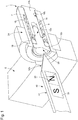
- La
figure 1 est une vue en perspective d'un mode de réalisation d'un bouton-poussoir de type correcteur dont l'actionnement peut être effectué au moyen d'un outil d'actionnement selon l'invention. On comprendra cependant que la description d'un tel bouton-poussoir correcteur est donnée à titre purement illustratif et nullement limitatif seulement. Comme on le verra ci-dessous, il s'agit d'un bouton-poussoir correcteur de type conventionnel dont la structure n'a tout au plus besoin d'être modifiée que pour ce qui est du choix du matériau dans lequel sont réalisés ses composants, alors que dans certaines formes de réalisation de l'invention, la structure du bouton-poussoir correcteur reste inchangée. - Désigné dans son ensemble par la référence numérique générale 1, un bouton-poussoir de type correcteur comprend classiquement une douille 2 par exemple chassée ou collée dans une ouverture 4 pratiquée dans une carrure 6 d'un objet portable, par exemple une montre-bracelet dont la carrure est réalisée dans un matériau précieux ou bien un téléphone intelligent.
- Une tige de commande 8 cylindrique est apte à coulisser dans la douille 2. La douille 2 comprend à cet effet un premier passage cylindrique 10a qui débouche du côté extérieur de la carrure 6 de l'objet portable et qui est adapté aux dimensions d'une première portion 12a de la tige de commande 8. Du côté intérieur de la carrure 6, la douille 2 comprend un second passage cylindrique 10b agencé dans le prolongement du premier passage cylindrique 10a et qui définit un épaulement 14 à l'intérieur de la douille 2. Le diamètre intérieur de ce second passage cylindrique 10b, adapté aux dimensions d'une seconde portion 12b de la tige de commande 8, est inférieur à celui du premier passage cylindrique 10a. Une garniture d'étanchéité 16 logée dans une saignée ménagée sur un périmètre de la première portion 12a de la tige de commande 8 permet de garantir l'étanchéité entre la tige de commande 8 et la douille 2. Un tel bouton-poussoir correcteur 1 comprend également un ressort hélicoïdal 18 qui se comprime lorsque l'utilisateur appuie sur le bouton-poussoir correcteur 1, et dont la force de rappel ramène la tige de commande 8 en position de repos lorsque l'utilisateur relâche la pression sur le bouton-poussoir correcteur 1. Le ressort hélicoïdal 18 est en appui contre une rondelle 20 montée fixe sur la première portion 12a de la tige de commande 8 à une extrémité, et contre l'épaulement 14 à l'autre extrémité.
- Des boutons-poussoirs du type décrit ci-dessus ont des dimensions très réduites. Ils permettent donc de gagner de la place. En outre, ils ne font pas saillie de la carrure et ne risquent donc pas d'être actionnés involontairement. De tels boutons-poussoirs équipent fréquemment des montres haut de gamme dites à complications. Les opérations de correction se font au moyen d'un instrument pointu tel qu'un stylo par exemple. Ce dernier point pose cependant problème. En effet, les montres-bracelets à complications sont des montres onéreuses dont les boîtes de montres sont très souvent réalisées à l'aide de matériaux précieux. Or, les risques de blesser la boîte de la montre et d'altérer son aspect esthétique lorsqu'on manipule un instrument pointu sont importants, ce qui est devenu difficilement acceptable.
- Pour pallier ce problème, la présente invention enseigne que l'un au moins des composants du bouton-poussoir correcteur 1 détaillé ci-dessus est réalisé au moyen d'un matériau ferromagnétique, c'est-à-dire un matériau qui soit magnétisable (voir
figures 2B et 2C ). Il peut s'agir, à titre purement illustratif et non limitatif, de la douille 2, ou bien encore de la tige de commande 8, ou bien de ces deux composants simultanément. Dans le cas où c'est par exemple la tige de commande 8 qui est réalisée en un matériau ferromagnétique, la carrure 6 de l'objet portable sera préférentiellement réalisée en un matériau non magnétisable. - On peut néanmoins envisager qu'au moins une portion 22 de la carrure 6 de l'objet portable située à proximité immédiate du bouton-poussoir correcteur 1 soit elle-aussi réalisée en un matériau ferromagnétique. De préférence, cette portion 22 de la carrure 6 sera agencée avec une symétrie circulaire autour du bouton-poussoir correcteur 1. Il pourra s'agir, par exemple, d'un anneau 24 disposé concentriquement autour de la douille 2 (voir
figures 3B et 3C ). Il pourra également s'agir, par exemple, de deux plots 26a et 26b réalisés en un matériau ferromagnétique et préférentiellement disposés de manière diamétralement opposée par rapport au centre 28 du bouton-poussoir correcteur 1 matérialisé par la tige de commande 8 (voirfigures 4B et 4C ). De même, il est envisageable qu'aucun des composants du bouton-poussoir correcteur 1 ne soit réalisé en un matériau ferromagnétique, seule une portion 22 de la carrure 6 étant alors réalisée en un tel matériau ferromagnétique. - Par « proximité immédiate », on entend que la portion 22 de la carrure 6 est disposée suffisamment proche du bouton-poussoir correcteur 1 pour que, lorsque l'utilisateur approche l'outil d'actionnement 30 selon l'invention du bouton-poussoir correcteur 1, l'attraction magnétique exercée sur cet outil d'actionnement 30 guide cet outil 30 vers la tige de commande 8, c'est-à-dire vers le centre 28 du bouton-poussoir correcteur 1. Il suffit ensuite à l'utilisateur d'exercer une poussée sur l'outil d'actionnement 30 pour pouvoir actionner le bouton-poussoir correcteur 1.
- Plus précisément, en ce qui concerne l'outil d'actionnement 30 selon l'invention, celui-ci comprend un corps 32 qui s'étend entre une extrémité arrière 32a qui définit une zone de préhension de cet outil d'actionnement 30, et une extrémité avant 32b qui définit une zone d'actionnement de cet outil 30. Selon une forme de réalisation de l'invention, l'outil d'actionnement 30 est entièrement réalisé en un matériau magnétique et est attiré par le matériau ferromagnétique dans lequel est réalisé au moins une portion 22 de la carrure et/ou l'un au moins des composants du bouton-poussoir correcteur 1. Ainsi, lorsque l'on approche l'outil d'actionnement 30 de l'objet portable, cet outil d'actionnement 30 est irrésistiblement attiré par le bouton-poussoir correcteur 1, vers le centre 28 de ce dernier. Selon une autre forme de réalisation de l'invention illustrée aux
figures 2A ,3A ,4A et6A , un barreau aimanté 34 est disposé dans un logement 36 ménagé dans l'extrémité avant 32b du corps 32 qui définit la zone d'actionnement de l'outil d'actionnement 30. - Le mode de réalisation décrit ci-dessus est particulièrement avantageux car, comme il ne fait intervenir un barreau aimanté 34 que du côté de l'outil d'actionnement 30, et que la carrure 6 et/ou le bouton-poussoir correcteur 1 comprennent uniquement un matériau ferromagnétique, il n'est pas nécessaire de se préoccuper de la polarité de l'aimant pour garantir l'attraction magnétique de l'outil d'actionnement 30 par l'objet portable.
- Une autre forme d'exécution de l'invention consiste à réaliser tout ou partie de l'outil d'actionnement en un matériau ferromagnétique et à disposer un aimant bipolaire dans l'objet portable. On peut ainsi envisager (voir
figure 5A ) que l'extrémité avant 32b qui définit la zone d'actionnement de l'outil d'actionnement 30 soit réalisée en un matériau ferromagnétique, et qu'au moins un composant du bouton-poussoir correcteur 1, par exemple la tige de commande 8 ou la douille 2, soit réalisé en un matériau magnétique. Il est aussi envisageable d'agencer au moins un et, de préférence, deux aimants bipolaires discrets 38a et 38b préférentiellement de manière diamétralement opposée par rapport au centre 28 du bouton-poussoir correcteur 1. De même, les aimants bipolaires discrets 38a, 38b peuvent être remplacés par un aimant annulaire 40 disposé autour de la douille 2 du bouton-poussoir correcteur 1, à faible distance de cette dernière (figures 5B et 5C ). - Dans ce cas également, on ne fait intervenir un aimant bipolaire 38, 40 que du côté de l'objet portable, de sorte qu'il n'est pas nécessaire de se préoccuper de la polarité de l'aimant pour garantir l'attraction magnétique de l'outil d'actionnement 30 par l'objet portable.
- Selon encore un autre mode de réalisation de l'invention, un aimant bipolaire 42 est agencé dans l'extrémité avant 32b de la zone d'actionnement de l'outil d'actionnement 30 (
figure 6A ), et au moins un composant du bouton-poussoir correcteur 1 et/ou au moins une portion 22 de la carrure 6 est réalisé en un matériau magnétique (figures 6B et 6C ). On comprendra que, dans ce mode de réalisation, il faut veiller à ce que la polarité magnétique de l'outil d'actionnement soit opposée à la polarité magnétique du bouton-poussoir correcteur 1. - Il va de soi que la présente invention n'est pas limitée aux modes de réalisation qui viennent d'être décrits et que diverses modifications et variantes simples peuvent être envisagées par l'homme du métier sans sortir du cadre de l'invention tel que défini par les revendications annexées.
-
- 1. Bouton-poussoir correcteur
- 2. Douille
- 4. Ouverture
- 6. Carrure
- 8. Tige de commande
- 10a. Premier passage cylindrique
- 10b. Second passage cylindrique
- 12a. Première portion
- 12b. Seconde portion
- 14. Epaulement
- 16. Garniture d'étanchéité
- 18. Ressort hélicoïdal
- 20. Rondelle
- 22. Portion
- 24. Anneau
- 26a, 26b. Plots
- 28. Centre
- 30. Outil d'actionnement
- 32. Corps
- 32a. Extrémité arrière
- 32b. Extrémité avant
- 34. Barreau aimanté
- 36. Logement
- 38a, 38b. Aimants bipolaires discrets
- 40. Aimant annulaire
- 42. Aimant bipolaire
Claims (6)
- Outil d'actionnement d'un bouton-poussoir correcteur (1) équipant un objet portable de petites dimensions, cet outil d'actionnement (30) comprenant un corps (32) qui s'étend entre une extrémité arrière (32a) qui définit une zone de préhension de l'outil d'actionnement (30) et une extrémité avant (32b) qui définit une zone d'actionnement de l'outil d'actionnement (30), au moins l'extrémité avant (32b) de l'outil d'actionnement (30) étant aimantée.
- Outil d'actionnement selon la revendication 1, caractérisé en ce qu'il comprend un barreau aimanté (34) agencé dans son extrémité avant (32b).
- Outil d'actionnement selon la revendication 1, caractérisé en ce que le corps (32) de l'outil d'actionnement (30) est réalisé au moyen d'un matériau magnétique.
- Objet portable de petites dimensions tel qu'une pièce d'horlogerie, cet objet portable comprenant une carrure (6) dans une ouverture (4) de laquelle est agencé un bouton-poussoir correcteur (1), au moins un composant du bouton-poussoir correcteur (1) ou au moins une zone (22) de la carrure (6) qui entoure immédiatement le bouton-poussoir correcteur (1) étant réalisé en un matériau ferromagnétique ou en un matériau magnétique.
- Ensemble comprenant un outil d'actionnement (30) d'un bouton-poussoir correcteur (1) équipant un objet portable de petites dimensions, cet outil d'actionnement (30) comprenant un corps (32) qui s'étend entre une extrémité arrière (32a) qui définit une zone de préhension de l'outil d'actionnement (30) et une extrémité avant (32b) qui définit une zone d'actionnement de l'outil d'actionnement (30), au moins l'extrémité avant (32b) de l'outil d'actionnement (30) étant aimantée, l'objet portable comprenant une carrure (6) dans une ouverture de laquelle est agencé un bouton-poussoir correcteur (1), au moins un élément du bouton-poussoir correcteur (1) ou bien au moins une portion (22) de la carrure (6) de l'objet portable qui entoure immédiatement le bouton-poussoir correcteur (1) étant réalisé en un matériau ferromagnétique ou en un matériau aimanté dont une première polarité magnétique est opposée à une seconde polarité magnétique de l'outil d'actionnement (30) aimanté.
- Ensemble comprenant un outil d'actionnement (30) d'un bouton-poussoir correcteur (1) équipant un objet portable de petites dimensions, cet outil d'actionnement (30) comprenant un corps (32) qui s'étend entre une extrémité arrière (32a) qui définit une zone de préhension de l'outil d'actionnement (30) et une extrémité avant (32b) qui définit une zone d'actionnement de l'outil d'actionnement (30), au moins l'extrémité avant (32b) de l'outil d'actionnement (30) étant réalisée en un matériau ferromagnétique, l'objet portable comprenant une carrure (6) dans une ouverture de laquelle est agencé un bouton-poussoir correcteur (1), au moins un composant du bouton-poussoir correcteur (1) ou bien au moins une portion (22) de la carrure (6) qui entoure immédiatement le bouton-poussoir correcteur (1) étant réalisé en un matériau magnétique.
Priority Applications (4)
| Application Number | Priority Date | Filing Date | Title |
|---|---|---|---|
| EP17200902.9A EP3483661B1 (fr) | 2017-11-09 | 2017-11-09 | Ensemble comprenant un objet portable de petites dimensions et un outil d'actionnement d'un bouton poussoir correcteur équipant ledit objet portable de petites dimensions tel qu'une pièce d'horlogerie |
| US16/136,500 US11262706B2 (en) | 2017-11-09 | 2018-09-20 | Tool for actuating a corrector fitted in a small portable object such as a timepiece |
| JP2018187203A JP6633711B2 (ja) | 2017-11-09 | 2018-10-02 | 計時器のような小型の携行可能な物に取り付けられたコレクターをアクチュエートする工具 |
| CN201811274395.9A CN109765776B (zh) | 2017-11-09 | 2018-10-30 | 用于致动安装在例如为钟表的小型便携式物体中的校正器的工具 |
Applications Claiming Priority (1)
| Application Number | Priority Date | Filing Date | Title |
|---|---|---|---|
| EP17200902.9A EP3483661B1 (fr) | 2017-11-09 | 2017-11-09 | Ensemble comprenant un objet portable de petites dimensions et un outil d'actionnement d'un bouton poussoir correcteur équipant ledit objet portable de petites dimensions tel qu'une pièce d'horlogerie |
Publications (2)
| Publication Number | Publication Date |
|---|---|
| EP3483661A1 true EP3483661A1 (fr) | 2019-05-15 |
| EP3483661B1 EP3483661B1 (fr) | 2024-06-05 |
Family
ID=60301845
Family Applications (1)
| Application Number | Title | Priority Date | Filing Date |
|---|---|---|---|
| EP17200902.9A Active EP3483661B1 (fr) | 2017-11-09 | 2017-11-09 | Ensemble comprenant un objet portable de petites dimensions et un outil d'actionnement d'un bouton poussoir correcteur équipant ledit objet portable de petites dimensions tel qu'une pièce d'horlogerie |
Country Status (4)
| Country | Link |
|---|---|
| US (1) | US11262706B2 (fr) |
| EP (1) | EP3483661B1 (fr) |
| JP (1) | JP6633711B2 (fr) |
| CN (1) | CN109765776B (fr) |
Cited By (1)
| Publication number | Priority date | Publication date | Assignee | Title |
|---|---|---|---|---|
| EP3825777A1 (fr) * | 2019-11-21 | 2021-05-26 | Meco S.A. | Correcteur de montre et carrure de montre |
Families Citing this family (2)
| Publication number | Priority date | Publication date | Assignee | Title |
|---|---|---|---|---|
| EP4198645B1 (fr) * | 2021-12-16 | 2025-11-19 | ETA SA Manufacture Horlogère Suisse | Dispositif de correction multifonction pour pièce d'horlogerie et pièce d'horlogerie comportant un tel dispositif de correction multifonction |
| EP4198638A1 (fr) * | 2021-12-16 | 2023-06-21 | ETA SA Manufacture Horlogère Suisse | Dispositif de correction multifonction pour piece d'horlogerie et outil d'actionnement d'un tel dispositif |
Citations (4)
| Publication number | Priority date | Publication date | Assignee | Title |
|---|---|---|---|---|
| FR2134533A1 (fr) * | 1971-04-29 | 1972-12-08 | Watch Hamilton Cy | |
| EP0224030A1 (fr) * | 1985-10-31 | 1987-06-03 | Montres Rado S.A. | Montre électronique avec système de commande dans le fond de la boîte |
| EP1835364A1 (fr) * | 2006-03-15 | 2007-09-19 | Seiko Epson Corporation | Structure bouton pour une pièce d'horlogerie et pièce d'horloge dotée de cette structure bouton |
| EP2077488A1 (fr) * | 2007-12-28 | 2009-07-08 | HTC Corporation | Stylet et dispositif électronique |
Family Cites Families (7)
| Publication number | Priority date | Publication date | Assignee | Title |
|---|---|---|---|---|
| CH576166B5 (fr) * | 1973-03-20 | 1976-05-31 | Ruhla Uhren Veb K | |
| JP4481195B2 (ja) | 2005-02-28 | 2010-06-16 | 株式会社日立国際電気 | 電子機器のスイッチ構造 |
| US20070171205A1 (en) * | 2006-01-24 | 2007-07-26 | Steinberg Dan A | Keyboard having magnet-actuted switches |
| US9195351B1 (en) * | 2011-09-28 | 2015-11-24 | Amazon Technologies, Inc. | Capacitive stylus |
| US9285903B1 (en) * | 2011-09-28 | 2016-03-15 | Amazon Technologies, Inc. | Stylus and electronic display |
| US20140168175A1 (en) * | 2012-12-13 | 2014-06-19 | Research In Motion Limited | Magnetically coupling stylus and host electronic device |
| US9298281B2 (en) * | 2012-12-27 | 2016-03-29 | Correlated Magnetics Research, Llc. | Magnetic vector sensor positioning and communications system |
-
2017
- 2017-11-09 EP EP17200902.9A patent/EP3483661B1/fr active Active
-
2018
- 2018-09-20 US US16/136,500 patent/US11262706B2/en active Active
- 2018-10-02 JP JP2018187203A patent/JP6633711B2/ja active Active
- 2018-10-30 CN CN201811274395.9A patent/CN109765776B/zh active Active
Patent Citations (4)
| Publication number | Priority date | Publication date | Assignee | Title |
|---|---|---|---|---|
| FR2134533A1 (fr) * | 1971-04-29 | 1972-12-08 | Watch Hamilton Cy | |
| EP0224030A1 (fr) * | 1985-10-31 | 1987-06-03 | Montres Rado S.A. | Montre électronique avec système de commande dans le fond de la boîte |
| EP1835364A1 (fr) * | 2006-03-15 | 2007-09-19 | Seiko Epson Corporation | Structure bouton pour une pièce d'horlogerie et pièce d'horloge dotée de cette structure bouton |
| EP2077488A1 (fr) * | 2007-12-28 | 2009-07-08 | HTC Corporation | Stylet et dispositif électronique |
Cited By (2)
| Publication number | Priority date | Publication date | Assignee | Title |
|---|---|---|---|---|
| EP3825777A1 (fr) * | 2019-11-21 | 2021-05-26 | Meco S.A. | Correcteur de montre et carrure de montre |
| US11994831B2 (en) | 2019-11-21 | 2024-05-28 | Meco Sa | Watch corrector and watch middle |
Also Published As
| Publication number | Publication date |
|---|---|
| JP6633711B2 (ja) | 2020-01-22 |
| US20190137938A1 (en) | 2019-05-09 |
| JP2019086512A (ja) | 2019-06-06 |
| US11262706B2 (en) | 2022-03-01 |
| EP3483661B1 (fr) | 2024-06-05 |
| CN109765776B (zh) | 2021-06-01 |
| CN109765776A (zh) | 2019-05-17 |
Similar Documents
| Publication | Publication Date | Title |
|---|---|---|
| EP2065767B1 (fr) | Dispositif de commande à poussoir | |
| CH713834A2 (fr) | Pièce d'horlogerie comportant un dispositif de verrouillage d'un poussoir. | |
| EP3483661B1 (fr) | Ensemble comprenant un objet portable de petites dimensions et un outil d'actionnement d'un bouton poussoir correcteur équipant ledit objet portable de petites dimensions tel qu'une pièce d'horlogerie | |
| CH685901B5 (fr) | Couronne-poussoir pour piece d'horlogerie. | |
| EP3451071A1 (fr) | Dispositif à poussoir pour pièce d'horlogerie | |
| EP3454138B1 (fr) | Outil d'actionnement d'un correcteur équipant une montre | |
| EP3454137B1 (fr) | Outil d'actionnement d'un correcteur équipant une montre | |
| EP3418814B1 (fr) | Dispositif de commande à couronne-poussoir pour un objet portable de petites dimensions | |
| EP0762241B1 (fr) | Pièce d'horlogerie comportant un mécanisme de commande à tige et à tirette | |
| CH713784B1 (fr) | Outil d'actionnement d'un correcteur équipant un objet portable de petites dimensions tel qu'une pièce d'horlogerie. | |
| BE505142A (fr) | ||
| EP3333648B1 (fr) | Dispositif pour la commande d'au moins deux fonctions électroniques et/ou mécaniques d'un objet portable | |
| CH714125B1 (fr) | Outil d'actionnement d'un correcteur équipant un objet portable de petites dimensions, tel qu'une pièce d'horlogerie. | |
| EP3056947A1 (fr) | Dispositif d actionnement d'une couronne dans une pièce d horlogerie et le procédé correspondant | |
| CH714124B1 (fr) | Outil d'actionnement pour un correcteur équipant un objet portable de petites dimensions, tel qu'une pièce d'horlogerie | |
| EP3825777B1 (fr) | Correcteur de montre et carrure de montre | |
| WO2005103844A1 (fr) | Dispositif correcteur pour piece d'horlogerie | |
| CH260357A (fr) | Palier pare-chocs pour mobiles de pièces d'horlogerie. | |
| EP4567525A1 (fr) | Dispositif de verrouillage d'un poussoir d'une boite de montre | |
| CH721369A2 (fr) | Dispositif de verrouillage d'un poussoir d'une boite de montre | |
| CH710434A2 (fr) | Arrangement de poussoir d'une pièce d'horlogerie. | |
| FR2996805A1 (fr) | Porte mine comprenant un guide-mine retractable | |
| FR2978257A1 (fr) | Dispositif manuel de reglage et/ou de correction des indications d'une montre | |
| CH715661B1 (fr) | Pièce d'horlogerie, notamment montre de poche, équipée d'un couvercle et d'un dispositif d'ouverture du couvercle. | |
| CH94051A (fr) | Montre-remontoir avec mécanisme de mise à l'heure. |
Legal Events
| Date | Code | Title | Description |
|---|---|---|---|
| PUAI | Public reference made under article 153(3) epc to a published international application that has entered the european phase |
Free format text: ORIGINAL CODE: 0009012 |
|
| STAA | Information on the status of an ep patent application or granted ep patent |
Free format text: STATUS: THE APPLICATION HAS BEEN PUBLISHED |
|
| AK | Designated contracting states |
Kind code of ref document: A1 Designated state(s): AL AT BE BG CH CY CZ DE DK EE ES FI FR GB GR HR HU IE IS IT LI LT LU LV MC MK MT NL NO PL PT RO RS SE SI SK SM TR |
|
| AX | Request for extension of the european patent |
Extension state: BA ME |
|
| STAA | Information on the status of an ep patent application or granted ep patent |
Free format text: STATUS: REQUEST FOR EXAMINATION WAS MADE |
|
| 17P | Request for examination filed |
Effective date: 20191115 |
|
| RBV | Designated contracting states (corrected) |
Designated state(s): AL AT BE BG CH CY CZ DE DK EE ES FI FR GB GR HR HU IE IS IT LI LT LU LV MC MK MT NL NO PL PT RO RS SE SI SK SM TR |
|
| STAA | Information on the status of an ep patent application or granted ep patent |
Free format text: STATUS: EXAMINATION IS IN PROGRESS |
|
| 17Q | First examination report despatched |
Effective date: 20210826 |
|
| P01 | Opt-out of the competence of the unified patent court (upc) registered |
Effective date: 20230611 |
|
| GRAP | Despatch of communication of intention to grant a patent |
Free format text: ORIGINAL CODE: EPIDOSNIGR1 |
|
| STAA | Information on the status of an ep patent application or granted ep patent |
Free format text: STATUS: GRANT OF PATENT IS INTENDED |
|
| INTG | Intention to grant announced |
Effective date: 20240215 |
|
| GRAS | Grant fee paid |
Free format text: ORIGINAL CODE: EPIDOSNIGR3 |
|
| GRAA | (expected) grant |
Free format text: ORIGINAL CODE: 0009210 |
|
| STAA | Information on the status of an ep patent application or granted ep patent |
Free format text: STATUS: THE PATENT HAS BEEN GRANTED |
|
| AK | Designated contracting states |
Kind code of ref document: B1 Designated state(s): AL AT BE BG CH CY CZ DE DK EE ES FI FR GB GR HR HU IE IS IT LI LT LU LV MC MK MT NL NO PL PT RO RS SE SI SK SM TR |
|
| REG | Reference to a national code |
Ref country code: GB Ref legal event code: FG4D Free format text: NOT ENGLISH |
|
| REG | Reference to a national code |
Ref country code: CH Ref legal event code: EP |
|
| REG | Reference to a national code |
Ref country code: DE Ref legal event code: R096 Ref document number: 602017082388 Country of ref document: DE |
|
| REG | Reference to a national code |
Ref country code: IE Ref legal event code: FG4D Free format text: LANGUAGE OF EP DOCUMENT: FRENCH |
|
| REG | Reference to a national code |
Ref country code: LT Ref legal event code: MG9D |
|
| PG25 | Lapsed in a contracting state [announced via postgrant information from national office to epo] |
Ref country code: BG Free format text: LAPSE BECAUSE OF FAILURE TO SUBMIT A TRANSLATION OF THE DESCRIPTION OR TO PAY THE FEE WITHIN THE PRESCRIBED TIME-LIMIT Effective date: 20240605 |
|
| REG | Reference to a national code |
Ref country code: NL Ref legal event code: MP Effective date: 20240605 |
|
| PG25 | Lapsed in a contracting state [announced via postgrant information from national office to epo] |
Ref country code: FI Free format text: LAPSE BECAUSE OF FAILURE TO SUBMIT A TRANSLATION OF THE DESCRIPTION OR TO PAY THE FEE WITHIN THE PRESCRIBED TIME-LIMIT Effective date: 20240605 Ref country code: HR Free format text: LAPSE BECAUSE OF FAILURE TO SUBMIT A TRANSLATION OF THE DESCRIPTION OR TO PAY THE FEE WITHIN THE PRESCRIBED TIME-LIMIT Effective date: 20240605 |
|
| PG25 | Lapsed in a contracting state [announced via postgrant information from national office to epo] |
Ref country code: GR Free format text: LAPSE BECAUSE OF FAILURE TO SUBMIT A TRANSLATION OF THE DESCRIPTION OR TO PAY THE FEE WITHIN THE PRESCRIBED TIME-LIMIT Effective date: 20240906 |
|
| PG25 | Lapsed in a contracting state [announced via postgrant information from national office to epo] |
Ref country code: ES Free format text: LAPSE BECAUSE OF FAILURE TO SUBMIT A TRANSLATION OF THE DESCRIPTION OR TO PAY THE FEE WITHIN THE PRESCRIBED TIME-LIMIT Effective date: 20240605 |
|
| PG25 | Lapsed in a contracting state [announced via postgrant information from national office to epo] |
Ref country code: LV Free format text: LAPSE BECAUSE OF FAILURE TO SUBMIT A TRANSLATION OF THE DESCRIPTION OR TO PAY THE FEE WITHIN THE PRESCRIBED TIME-LIMIT Effective date: 20240605 |
|
| PG25 | Lapsed in a contracting state [announced via postgrant information from national office to epo] |
Ref country code: NO Free format text: LAPSE BECAUSE OF FAILURE TO SUBMIT A TRANSLATION OF THE DESCRIPTION OR TO PAY THE FEE WITHIN THE PRESCRIBED TIME-LIMIT Effective date: 20240905 Ref country code: LV Free format text: LAPSE BECAUSE OF FAILURE TO SUBMIT A TRANSLATION OF THE DESCRIPTION OR TO PAY THE FEE WITHIN THE PRESCRIBED TIME-LIMIT Effective date: 20240605 Ref country code: HR Free format text: LAPSE BECAUSE OF FAILURE TO SUBMIT A TRANSLATION OF THE DESCRIPTION OR TO PAY THE FEE WITHIN THE PRESCRIBED TIME-LIMIT Effective date: 20240605 Ref country code: GR Free format text: LAPSE BECAUSE OF FAILURE TO SUBMIT A TRANSLATION OF THE DESCRIPTION OR TO PAY THE FEE WITHIN THE PRESCRIBED TIME-LIMIT Effective date: 20240906 Ref country code: FI Free format text: LAPSE BECAUSE OF FAILURE TO SUBMIT A TRANSLATION OF THE DESCRIPTION OR TO PAY THE FEE WITHIN THE PRESCRIBED TIME-LIMIT Effective date: 20240605 Ref country code: ES Free format text: LAPSE BECAUSE OF FAILURE TO SUBMIT A TRANSLATION OF THE DESCRIPTION OR TO PAY THE FEE WITHIN THE PRESCRIBED TIME-LIMIT Effective date: 20240605 Ref country code: BG Free format text: LAPSE BECAUSE OF FAILURE TO SUBMIT A TRANSLATION OF THE DESCRIPTION OR TO PAY THE FEE WITHIN THE PRESCRIBED TIME-LIMIT Effective date: 20240605 Ref country code: RS Free format text: LAPSE BECAUSE OF FAILURE TO SUBMIT A TRANSLATION OF THE DESCRIPTION OR TO PAY THE FEE WITHIN THE PRESCRIBED TIME-LIMIT Effective date: 20240905 |
|
| PG25 | Lapsed in a contracting state [announced via postgrant information from national office to epo] |
Ref country code: NL Free format text: LAPSE BECAUSE OF FAILURE TO SUBMIT A TRANSLATION OF THE DESCRIPTION OR TO PAY THE FEE WITHIN THE PRESCRIBED TIME-LIMIT Effective date: 20240605 |
|
| REG | Reference to a national code |
Ref country code: AT Ref legal event code: MK05 Ref document number: 1692896 Country of ref document: AT Kind code of ref document: T Effective date: 20240605 |
|
| PG25 | Lapsed in a contracting state [announced via postgrant information from national office to epo] |
Ref country code: NL Free format text: LAPSE BECAUSE OF FAILURE TO SUBMIT A TRANSLATION OF THE DESCRIPTION OR TO PAY THE FEE WITHIN THE PRESCRIBED TIME-LIMIT Effective date: 20240605 |
|
| PG25 | Lapsed in a contracting state [announced via postgrant information from national office to epo] |
Ref country code: PT Free format text: LAPSE BECAUSE OF FAILURE TO SUBMIT A TRANSLATION OF THE DESCRIPTION OR TO PAY THE FEE WITHIN THE PRESCRIBED TIME-LIMIT Effective date: 20241007 |
|
| PG25 | Lapsed in a contracting state [announced via postgrant information from national office to epo] |
Ref country code: PT Free format text: LAPSE BECAUSE OF FAILURE TO SUBMIT A TRANSLATION OF THE DESCRIPTION OR TO PAY THE FEE WITHIN THE PRESCRIBED TIME-LIMIT Effective date: 20241007 |
|
| PG25 | Lapsed in a contracting state [announced via postgrant information from national office to epo] |
Ref country code: PL Free format text: LAPSE BECAUSE OF FAILURE TO SUBMIT A TRANSLATION OF THE DESCRIPTION OR TO PAY THE FEE WITHIN THE PRESCRIBED TIME-LIMIT Effective date: 20240605 |
|
| PG25 | Lapsed in a contracting state [announced via postgrant information from national office to epo] |
Ref country code: EE Free format text: LAPSE BECAUSE OF FAILURE TO SUBMIT A TRANSLATION OF THE DESCRIPTION OR TO PAY THE FEE WITHIN THE PRESCRIBED TIME-LIMIT Effective date: 20240605 |
|
| PG25 | Lapsed in a contracting state [announced via postgrant information from national office to epo] |
Ref country code: AT Free format text: LAPSE BECAUSE OF FAILURE TO SUBMIT A TRANSLATION OF THE DESCRIPTION OR TO PAY THE FEE WITHIN THE PRESCRIBED TIME-LIMIT Effective date: 20240605 Ref country code: IS Free format text: LAPSE BECAUSE OF FAILURE TO SUBMIT A TRANSLATION OF THE DESCRIPTION OR TO PAY THE FEE WITHIN THE PRESCRIBED TIME-LIMIT Effective date: 20241005 |
|
| PG25 | Lapsed in a contracting state [announced via postgrant information from national office to epo] |
Ref country code: CZ Free format text: LAPSE BECAUSE OF FAILURE TO SUBMIT A TRANSLATION OF THE DESCRIPTION OR TO PAY THE FEE WITHIN THE PRESCRIBED TIME-LIMIT Effective date: 20240605 |
|
| PG25 | Lapsed in a contracting state [announced via postgrant information from national office to epo] |
Ref country code: RO Free format text: LAPSE BECAUSE OF FAILURE TO SUBMIT A TRANSLATION OF THE DESCRIPTION OR TO PAY THE FEE WITHIN THE PRESCRIBED TIME-LIMIT Effective date: 20240605 Ref country code: SK Free format text: LAPSE BECAUSE OF FAILURE TO SUBMIT A TRANSLATION OF THE DESCRIPTION OR TO PAY THE FEE WITHIN THE PRESCRIBED TIME-LIMIT Effective date: 20240605 |
|
| PG25 | Lapsed in a contracting state [announced via postgrant information from national office to epo] |
Ref country code: SM Free format text: LAPSE BECAUSE OF FAILURE TO SUBMIT A TRANSLATION OF THE DESCRIPTION OR TO PAY THE FEE WITHIN THE PRESCRIBED TIME-LIMIT Effective date: 20240605 |
|
| PG25 | Lapsed in a contracting state [announced via postgrant information from national office to epo] |
Ref country code: SM Free format text: LAPSE BECAUSE OF FAILURE TO SUBMIT A TRANSLATION OF THE DESCRIPTION OR TO PAY THE FEE WITHIN THE PRESCRIBED TIME-LIMIT Effective date: 20240605 Ref country code: SK Free format text: LAPSE BECAUSE OF FAILURE TO SUBMIT A TRANSLATION OF THE DESCRIPTION OR TO PAY THE FEE WITHIN THE PRESCRIBED TIME-LIMIT Effective date: 20240605 Ref country code: RO Free format text: LAPSE BECAUSE OF FAILURE TO SUBMIT A TRANSLATION OF THE DESCRIPTION OR TO PAY THE FEE WITHIN THE PRESCRIBED TIME-LIMIT Effective date: 20240605 Ref country code: PL Free format text: LAPSE BECAUSE OF FAILURE TO SUBMIT A TRANSLATION OF THE DESCRIPTION OR TO PAY THE FEE WITHIN THE PRESCRIBED TIME-LIMIT Effective date: 20240605 Ref country code: IS Free format text: LAPSE BECAUSE OF FAILURE TO SUBMIT A TRANSLATION OF THE DESCRIPTION OR TO PAY THE FEE WITHIN THE PRESCRIBED TIME-LIMIT Effective date: 20241005 Ref country code: EE Free format text: LAPSE BECAUSE OF FAILURE TO SUBMIT A TRANSLATION OF THE DESCRIPTION OR TO PAY THE FEE WITHIN THE PRESCRIBED TIME-LIMIT Effective date: 20240605 Ref country code: CZ Free format text: LAPSE BECAUSE OF FAILURE TO SUBMIT A TRANSLATION OF THE DESCRIPTION OR TO PAY THE FEE WITHIN THE PRESCRIBED TIME-LIMIT Effective date: 20240605 Ref country code: AT Free format text: LAPSE BECAUSE OF FAILURE TO SUBMIT A TRANSLATION OF THE DESCRIPTION OR TO PAY THE FEE WITHIN THE PRESCRIBED TIME-LIMIT Effective date: 20240605 |
|
| PG25 | Lapsed in a contracting state [announced via postgrant information from national office to epo] |
Ref country code: IT Free format text: LAPSE BECAUSE OF FAILURE TO SUBMIT A TRANSLATION OF THE DESCRIPTION OR TO PAY THE FEE WITHIN THE PRESCRIBED TIME-LIMIT Effective date: 20240605 |
|
| REG | Reference to a national code |
Ref country code: DE Ref legal event code: R097 Ref document number: 602017082388 Country of ref document: DE |
|
| PLBE | No opposition filed within time limit |
Free format text: ORIGINAL CODE: 0009261 |
|
| STAA | Information on the status of an ep patent application or granted ep patent |
Free format text: STATUS: NO OPPOSITION FILED WITHIN TIME LIMIT |
|
| PG25 | Lapsed in a contracting state [announced via postgrant information from national office to epo] |
Ref country code: DK Free format text: LAPSE BECAUSE OF FAILURE TO SUBMIT A TRANSLATION OF THE DESCRIPTION OR TO PAY THE FEE WITHIN THE PRESCRIBED TIME-LIMIT Effective date: 20240605 |
|
| 26N | No opposition filed |
Effective date: 20250306 |
|
| PG25 | Lapsed in a contracting state [announced via postgrant information from national office to epo] |
Ref country code: MC Free format text: LAPSE BECAUSE OF FAILURE TO SUBMIT A TRANSLATION OF THE DESCRIPTION OR TO PAY THE FEE WITHIN THE PRESCRIBED TIME-LIMIT Effective date: 20240605 |
|
| PG25 | Lapsed in a contracting state [announced via postgrant information from national office to epo] |
Ref country code: LU Free format text: LAPSE BECAUSE OF NON-PAYMENT OF DUE FEES Effective date: 20241109 |
|
| REG | Reference to a national code |
Ref country code: BE Ref legal event code: MM Effective date: 20241130 |
|
| PG25 | Lapsed in a contracting state [announced via postgrant information from national office to epo] |
Ref country code: SE Free format text: LAPSE BECAUSE OF FAILURE TO SUBMIT A TRANSLATION OF THE DESCRIPTION OR TO PAY THE FEE WITHIN THE PRESCRIBED TIME-LIMIT Effective date: 20240605 |
|
| PG25 | Lapsed in a contracting state [announced via postgrant information from national office to epo] |
Ref country code: BE Free format text: LAPSE BECAUSE OF NON-PAYMENT OF DUE FEES Effective date: 20241130 |
|
| PG25 | Lapsed in a contracting state [announced via postgrant information from national office to epo] |
Ref country code: IE Free format text: LAPSE BECAUSE OF NON-PAYMENT OF DUE FEES Effective date: 20241109 |
|
| REG | Reference to a national code |
Ref country code: CH Ref legal event code: U11 Free format text: ST27 STATUS EVENT CODE: U-0-0-U10-U11 (AS PROVIDED BY THE NATIONAL OFFICE) Effective date: 20251201 |
|
| PGFP | Annual fee paid to national office [announced via postgrant information from national office to epo] |
Ref country code: DE Payment date: 20251022 Year of fee payment: 9 |
|
| PGFP | Annual fee paid to national office [announced via postgrant information from national office to epo] |
Ref country code: GB Payment date: 20251022 Year of fee payment: 9 |
|
| PGFP | Annual fee paid to national office [announced via postgrant information from national office to epo] |
Ref country code: FR Payment date: 20251023 Year of fee payment: 9 |
|
| PGFP | Annual fee paid to national office [announced via postgrant information from national office to epo] |
Ref country code: CH Payment date: 20251201 Year of fee payment: 9 |
|
| PG25 | Lapsed in a contracting state [announced via postgrant information from national office to epo] |
Ref country code: HU Free format text: LAPSE BECAUSE OF FAILURE TO SUBMIT A TRANSLATION OF THE DESCRIPTION OR TO PAY THE FEE WITHIN THE PRESCRIBED TIME-LIMIT; INVALID AB INITIO Effective date: 20171109 |
|
| PG25 | Lapsed in a contracting state [announced via postgrant information from national office to epo] |
Ref country code: CY Free format text: LAPSE BECAUSE OF FAILURE TO SUBMIT A TRANSLATION OF THE DESCRIPTION OR TO PAY THE FEE WITHIN THE PRESCRIBED TIME-LIMIT; INVALID AB INITIO Effective date: 20171109 |