EP3483541A1 - Aufnahmevorrichtung für behandlungsvorrichtungen für metallurgische gefässe - Google Patents
Aufnahmevorrichtung für behandlungsvorrichtungen für metallurgische gefässe Download PDFInfo
- Publication number
- EP3483541A1 EP3483541A1 EP18205328.0A EP18205328A EP3483541A1 EP 3483541 A1 EP3483541 A1 EP 3483541A1 EP 18205328 A EP18205328 A EP 18205328A EP 3483541 A1 EP3483541 A1 EP 3483541A1
- Authority
- EP
- European Patent Office
- Prior art keywords
- side walls
- metallurgical
- front plate
- receiving device
- copper
- Prior art date
- Legal status (The legal status is an assumption and is not a legal conclusion. Google has not performed a legal analysis and makes no representation as to the accuracy of the status listed.)
- Withdrawn
Links
Images

Classifications
-
- F—MECHANICAL ENGINEERING; LIGHTING; HEATING; WEAPONS; BLASTING
- F27—FURNACES; KILNS; OVENS; RETORTS
- F27B—FURNACES, KILNS, OVENS OR RETORTS IN GENERAL; OPEN SINTERING OR LIKE APPARATUS
- F27B3/00—Hearth-type furnaces, e.g. of reverberatory type; Electric arc furnaces ; Tank furnaces
- F27B3/10—Details, accessories or equipment, e.g. dust-collectors, specially adapted for hearth-type furnaces
- F27B3/22—Arrangements of air or gas supply devices
-
- C—CHEMISTRY; METALLURGY
- C21—METALLURGY OF IRON
- C21C—PROCESSING OF PIG-IRON, e.g. REFINING, MANUFACTURE OF WROUGHT-IRON OR STEEL; TREATMENT IN MOLTEN STATE OF FERROUS ALLOYS
- C21C5/00—Manufacture of carbon-steel, e.g. plain mild steel, medium carbon steel or cast steel or stainless steel
- C21C5/52—Manufacture of steel in electric furnaces
- C21C5/5211—Manufacture of steel in electric furnaces in an alternating current [AC] electric arc furnace
- C21C5/5217—Manufacture of steel in electric furnaces in an alternating current [AC] electric arc furnace equipped with burners or devices for injecting gas, i.e. oxygen, or pulverulent materials into the furnace
-
- F—MECHANICAL ENGINEERING; LIGHTING; HEATING; WEAPONS; BLASTING
- F27—FURNACES; KILNS; OVENS; RETORTS
- F27D—DETAILS OR ACCESSORIES OF FURNACES, KILNS, OVENS OR RETORTS, IN SO FAR AS THEY ARE OF KINDS OCCURRING IN MORE THAN ONE KIND OF FURNACE
- F27D3/00—Charging; Discharging; Manipulation of charge
- F27D3/16—Introducing a fluid jet or current into the charge
-
- F—MECHANICAL ENGINEERING; LIGHTING; HEATING; WEAPONS; BLASTING
- F27—FURNACES; KILNS; OVENS; RETORTS
- F27D—DETAILS OR ACCESSORIES OF FURNACES, KILNS, OVENS OR RETORTS, IN SO FAR AS THEY ARE OF KINDS OCCURRING IN MORE THAN ONE KIND OF FURNACE
- F27D9/00—Cooling of furnaces or of charges therein
-
- C—CHEMISTRY; METALLURGY
- C21—METALLURGY OF IRON
- C21B—MANUFACTURE OF IRON OR STEEL
- C21B7/00—Blast furnaces
- C21B7/10—Cooling; Devices therefor
-
- C—CHEMISTRY; METALLURGY
- C21—METALLURGY OF IRON
- C21C—PROCESSING OF PIG-IRON, e.g. REFINING, MANUFACTURE OF WROUGHT-IRON OR STEEL; TREATMENT IN MOLTEN STATE OF FERROUS ALLOYS
- C21C5/00—Manufacture of carbon-steel, e.g. plain mild steel, medium carbon steel or cast steel or stainless steel
- C21C5/28—Manufacture of steel in the converter
- C21C5/42—Constructional features of converters
- C21C5/46—Details or accessories
- C21C5/4606—Lances or injectors
-
- F—MECHANICAL ENGINEERING; LIGHTING; HEATING; WEAPONS; BLASTING
- F27—FURNACES; KILNS; OVENS; RETORTS
- F27D—DETAILS OR ACCESSORIES OF FURNACES, KILNS, OVENS OR RETORTS, IN SO FAR AS THEY ARE OF KINDS OCCURRING IN MORE THAN ONE KIND OF FURNACE
- F27D3/00—Charging; Discharging; Manipulation of charge
- F27D3/16—Introducing a fluid jet or current into the charge
- F27D2003/168—Introducing a fluid jet or current into the charge through a lance
- F27D2003/169—Construction of the lance, e.g. lances for injecting particles
-
- F—MECHANICAL ENGINEERING; LIGHTING; HEATING; WEAPONS; BLASTING
- F27—FURNACES; KILNS; OVENS; RETORTS
- F27D—DETAILS OR ACCESSORIES OF FURNACES, KILNS, OVENS OR RETORTS, IN SO FAR AS THEY ARE OF KINDS OCCURRING IN MORE THAN ONE KIND OF FURNACE
- F27D9/00—Cooling of furnaces or of charges therein
- F27D2009/0002—Cooling of furnaces
- F27D2009/001—Cooling of furnaces the cooling medium being a fluid other than a gas
- F27D2009/0013—Cooling of furnaces the cooling medium being a fluid other than a gas the fluid being water
-
- F—MECHANICAL ENGINEERING; LIGHTING; HEATING; WEAPONS; BLASTING
- F27—FURNACES; KILNS; OVENS; RETORTS
- F27D—DETAILS OR ACCESSORIES OF FURNACES, KILNS, OVENS OR RETORTS, IN SO FAR AS THEY ARE OF KINDS OCCURRING IN MORE THAN ONE KIND OF FURNACE
- F27D9/00—Cooling of furnaces or of charges therein
- F27D2009/0002—Cooling of furnaces
- F27D2009/0045—Cooling of furnaces the cooling medium passing a block, e.g. metallic
- F27D2009/0048—Cooling of furnaces the cooling medium passing a block, e.g. metallic incorporating conduits for the medium
-
- Y—GENERAL TAGGING OF NEW TECHNOLOGICAL DEVELOPMENTS; GENERAL TAGGING OF CROSS-SECTIONAL TECHNOLOGIES SPANNING OVER SEVERAL SECTIONS OF THE IPC; TECHNICAL SUBJECTS COVERED BY FORMER USPC CROSS-REFERENCE ART COLLECTIONS [XRACs] AND DIGESTS
- Y02—TECHNOLOGIES OR APPLICATIONS FOR MITIGATION OR ADAPTATION AGAINST CLIMATE CHANGE
- Y02P—CLIMATE CHANGE MITIGATION TECHNOLOGIES IN THE PRODUCTION OR PROCESSING OF GOODS
- Y02P10/00—Technologies related to metal processing
- Y02P10/20—Recycling
Definitions
- the present invention relates to a receiving device for the protection of treatment devices in the metallurgical treatment of a melt in a metallurgical vessel.
- treatment devices are understood to mean, for example, injectors, thermal lances or measuring probes and the like, but are by no means limited thereto.
- Receiving devices for injectors in a melting furnace for example, from EP 1 553 192 A2 known. They are made of solid copper and / or steel sheets and are exposed to high levels of heat during use. They are therefore subject to relatively high wear and cause high, costly repairs.
- the object of the present invention is to provide a cost-effective receiving device for protecting the injectors for the metallurgical treatment of melts.
- Such copper-clad steel sheets for the outer skin are used only in the hot area. The production is thereby simplified and the manufacturing costs are reduced. A Expensive and expensive construction and repairs only by professionals are avoided because the previously required pure copper welds and copper / steel welds are not required. This makes a simple repair before the place possible.
- the back plate of the receiving device may be provided with lateral projections for engagement with an opening of a metallurgical vessel and with retaining tabs.
- the receiving device is usually installed from the outside to the inside of the wall of a vessel shell.
- the lateral projections or the lateral projection thus serves on the one hand to seal against the vessel interior, on the other hand it serves for fastening the receiving device, for example by means of bolt-wedge connections.
- the front plate and the side walls can be flowed through by a coolant.
- the front panel can be connected by means of screw, wedge or welded connection with the side walls of the receiving device.
- Front panel and side wall apparatus for use in a melting vessel, in particular for molten steel, with passages for introducing lances, injectors and probes for supplying means for metallurgical treatment of the melt contained in the metallurgical vessel, the apparatus being clad with copper Shell can be assigned in the hot area.
- FIG. 1 shows the isometric view of a receiving device 10 according to the invention for the protection of treatment devices in the metallurgical treatment of a melt in a metallurgical vessel.
- the treatment devices can be, for example, injectors, lances or measuring probes and the like.
- the receiving device 10 is designed as a box-like box 10a and has an access 11 in the installed position at the rear.
- the access 11 makes it possible to reach the interior of the receiving device 10 unhindered.
- the receiving device 10 may also be referred to as a hybrid box. This is to make it clear that the front plate 12 made of copper-clad sheet steel and the side walls 13 may either consist of sheet steel or also of a material mix of sheet steel with copper-clad steel sheet.
- the side walls 13 are fixedly connected to a rear plate 14.
- the rear plate 14 has a circumferential lateral projection 14a, which can be temporarily connected to the outer surface of the metallurgical vessel for better sealing against an opening of a - not shown - metallurgical vessel, such as a melting vessel. This can be done by fixing the rear plate 14 to the metallurgical vessel, for example by means of bolts, by means of bores 15 associated with the lateral projection 14a.
- the front panel 12 is provided with a plurality of passages 16 through which treatment devices (not shown), such as injectors or lances, may be introduced for metallurgical treatment of a melt into the metallurgical vessel, such as an electric arc furnace.
- treatment devices such as injectors or lances
- the injectors are thus relatively protected against heat radiation and exposed to less wear.
- a coolant circuit (not shown) is arranged in the box 10a (hybrid box).
- the coolant circuit has an inlet and outlet 17 and is supplied here with a coolant.
- the supply and return lines 17 of the coolant circuit can be designed differently.
- the front panel 12 can be removed from the side walls 13.
- the side walls 13 on the inside retaining tabs 18 are assigned.
- the front panel 12 can thereby be releasably connected to the side walls 13 in a sealing manner.
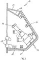
- the Fig. 3 shows a possible embodiment of the receiving device 10 according to the invention, in which the front plate 12 by means of bolts 21 and retaining tabs 18 (angle pieces) relative to the side walls 13 (perspective only one shown) can be set.
- a holding device 22 for example for an injector and other accessories, on one of the passages 16 is arranged, with which then the injector via the holding device 22 through a passage 16 in the metallurgical vessel (not shown) can be introduced.
- At least one supply and return 17 are provided for a coolant circuit in this embodiment of the receiving device 10.
- the coolant circuit may for example comprise a part of a double-walled cover plate 23, which connects the side walls 13 with each other. Through the cavity 24 created thereby, a coolant can circulate, via which the heat introduced into the receiving device 10 can be absorbed and ultimately dissipated.
Landscapes
- Engineering & Computer Science (AREA)
- Mechanical Engineering (AREA)
- General Engineering & Computer Science (AREA)
- Chemical & Material Sciences (AREA)
- Manufacturing & Machinery (AREA)
- Materials Engineering (AREA)
- Metallurgy (AREA)
- Organic Chemistry (AREA)
- Manufacture And Refinement Of Metals (AREA)
Abstract
Description
- Die vorliegende Erfindung betrifft eine Aufnahmevorrichtung zum Schutz von Behandlungsvorrichtungen bei der metallurgischen Behandlung einer Schmelze in einem metallurgischen Gefäß. Unter dem Begriff Behandlungsvorrichtungen werden beispielsweise Injektoren, thermische Lanzen oder Messsonden und dgl. verstanden, sind aber keineswegs hierauf beschränkt.
- Aufnahmevorrichtungen für Injektoren in einem Schmelzofen sind beispielsweise aus der
EP 1 553 192 A2 bekannt. Sie bestehen aus massivem Kupfer und/oder Stahlblechen und sind im Einsatz einer hohen Hitzebelastung ausgesetzt. Sie unterliegen dadurch einem relativ hohen Verschleiß und verursachen hohe, kostenaufwendige Reparaturen. - Aufgabe der vorliegenden Erfindung ist es, eine kostengünstige Aufnahmevorrichtung zum Schutz der Injektoren für die metallurgische Behandlung von Schmelzen zu schaffen.
- Diese Aufgabe wird durch die im Anspruch 1 angegebenen Merkmale gelöst, insbesondere dadurch, dass die Frontplatte und auch die Seitenwände aus kupferplattiertem Stahl bestehen.
- Derartige kupferplattierte Stahlbleche für die Außenhaut werden lediglich im Heißbereich eingesetzt. Die Fertigung wird dadurch vereinfacht und die Herstellungskosten werden verringert. Eine aufwendige und teure Konstruktion und Reparaturen nur durch Fachleute werden vermieden, da die bisher erforderlichen reinen Kupferschweißungen und Kupfer/Stahlschweißungen nicht erforderlich sind. Dadurch wird eine einfache Reparatur vor auch Ort möglich.
- Gemäß einer Ausführungsform der erfindungsgemäßen Vorrichtung kann das Rückenblech der Aufnahmevorrichtung mit seitlichen Überständen zur Anlage an eine Öffnung eines metallurgischen Gefäßes und mit Haltelaschen versehen sein.
- Die Aufnahmevorrichtung wird in der Regel von außen nach innen in die Wandung eines Gefäßoberteils eingebaut. Die seitlichen Überstände bzw. der seitliche Überstand dient damit einerseits zur Abdichtung gegen den Gefäßinnenraum, andererseits dient er zur Befestigung der Aufnahmevorrichtung, beispielsweise mit Hilfe von Bolzen-Keil-Verbindungen.
- Als weitere Ausgestaltung der Erfindung können die Frontplatte und die Seitenwände von einem Kühlmittel durchströmt werden.
- Des Weiteren kann die Frontplatte mittels Schraub-, Keil-, oder Schweißverbindung mit den Seitenwänden der Aufnahmevorrichtung verbinden werden.
- Aus einer Frontplatte und Seitenwänden bestehende Vorrichtung zum Ansetzen an ein Schmelzgefäß, insbesondere für Stahlschmelzen, mit Durchlässen zur Einführung von Lanzen, Injektoren und Sonden für die Zufuhr von Mitteln zur metallurgischen Behandlung der in dem metallurgischen Gefäß befindlichen Schmelze, wobei der Vorrichtung eine mit Kupfer plattierte Außenhaut im Heißbereich zugeordnet sein kann.
- Weitere vorteilhafte Maßnahmen sind in den Unteransprüchen beschrieben. Die Erfindung ist in den beiliegenden Zeichnungen dargestellt und wird nachfolgend näher beschrieben. Es zeigen:
- Fig. 1
- Eine isometrische Darstellung der erfindungsgemäßen Aufnahmevorrichtung in einer ersten Ausführungsform mit einem Vor- und Rücklauf für ein Kühlmittel;
- Fig. 2
- die isometrische Darstellung der erfindungsgemäßen Aufnahmevorrichtung mit abgenommener Frontplatte, wobei hier der Vor- und Rücklauf für das Kühlmittel gegenüber der
Fig. 1 gekröpft ausgebildet ist; - Fig. 3
- eine Darstellung im Schnitt durch die erfindungsgemäße Aufnahmevorrichtung in einer Ausführungsform mit einer darin angeordneten Injektor-Aufnahme;
- Die
Figur 1 zeigt die isometrische Darstellung einer erfindungsgemäßen Aufnahmevorrichtung 10 zum Schutz von Behandlungsvorrichtungen bei der metallurgischen Behandlung einer Schmelze in einem metallurgischen Gefäß. Wie eingangs schon erwähnt, können die Behandlungsvorrichtungen beispielsweise Injektoren, Lanzen oder Messsonden und dergleichen sein. - Die Aufnahmevorrichtung 10 ist als kastenartige Box 10a ausgebildet und weist in Einbaulage hinten einen Zugang 11 auf. Der Zugang 11 ermöglicht es, das Innere der Aufnahmevorrichtung 10 ungehindert zu erreichen. Die Aufnahmevorrichtung 10 kann auch als Hybridbox bezeichnet werden. Hierdurch soll verdeutlicht werden, dass die Frontplatte 12 aus kupferplattiertem Stahlblech und die Seitenwände 13 entweder aus Stahlblech oder ebenfalls aus einem Materialmix aus Stahlblech mit kupferplattiertem Stahlblech bestehen kann.
- Die Seitenwände 13 sind fest mit einem Rückblech 14 verbunden. Das Rückblech 14 weist einen rundumlaufenden seitlichen Überstand 14a auf, der zur besseren Abdichtung gegenüber einer Öffnung eines - nicht dargestellten - metallurgischen Gefäßes, beispielsweise eines Schmelzgefäßes, mit der Außenoberfläche des metallurgischen Gefäßes temporär verbunden werden kann. Dies kann dadurch geschehen, dass das Rückblech 14 beispielsweise durch Schraubbolzen mittels dem seitlichen Überstand 14a zugeordneten Bohrungen 15 gegenüber dem metallurgischen Gefäß festgelegt wird.
- Wie in der
Fig. 2 dargestellt, ist die Frontplatte 12 mit einer Vielzahl von Durchlässen 16 versehen, durch die Behandlungsvorrichtungen (nicht dargestellt), beispielsweise Injektoren oder Lanzen, für eine metallurgische Behandlung einer Schmelze in das metallurgische Gefäß, beispielsweise einem Elektrolichtbogenofen, eingeführt werden können. Die Injektoren sind dadurch gegen die Hitzestrahlung verhältnismäßig geschützt und geringerem Verschleiß ausgesetzt. - Zur Kühlung der Aufnahmevorrichtung 10 ist in der Box 10a (Hybridbox) ein Kühlmittelkreislauf (nicht dargestellt) angeordnet. Der Kühlmittelkreislauf weist einen Zu- und Rücklauf 17 auf und wird hierüber mit einem Kühlmittel versorgt. Wie in
Fig. 1 und Fig. 2 dargestellt, können die Zu- und Rückläufe 17 des Kühlmittelkreislaufs unterschiedlich ausgebildet sein. - Wie die
Fig. 2 des Weiteren zeigt, kann die Frontplatte 12 von den Seitenwänden 13 abgenommen werden. In dieser Ausführungsform sind den Seitenwänden 13 an deren Innenseiten Haltelaschen 18 (Winkelstücke) zugeordnet. Die Frontplatte 12 kann hierdurch abdichtend mit den Seitenwänden 13 lösbar verbunden werden. - Dabei ist vorgesehen, dass das auf dem Stahlblech 19 aufplattierte Kupferblech 20 der Frontplatte 12 im zusammengebauten Zustand, sprich in der Einsatzposition, erhaben gegenüber den Seitenwänden 13 angeordnet ist, wobei hingegen das Stahlblech 19 bündig mit den Seitenwänden 13 abschließt, wie dies insbesondere in
Fig. 3 dargestellt ist. - Die
Fig. 3 zeigt eine mögliche Ausführungsform der erfindungsgemäßen Aufnahmevorrichtung 10, bei der die Frontplatte 12 mittels Schraubenbolzen 21 und Haltelaschen 18 (Winkelstücke) gegenüber den Seitenwänden 13 (perspektivbedingt nur eine dargestellt) festgelegt werden kann. In der Frontplatte 12 ist eine Haltevorrichtung 22, beispielsweise für einen Injektor und für weitere Zusatzgeräte, auf einen der Durchlässe 16 angeordnet, mit dem sodann der Injektor über die Haltevorrichtung 22 durch einen Durchlass 16 in das metallurgische Gefäß (nicht dargestellt) eingeführt werden kann. - Wie schon in den
Figuren 1 und 2 dargestellt, sind auch in dieser Ausführungsform der Aufnahmevorrichtung 10 mindestens ein Zu- und Rücklauf 17 für einen Kühlmittelkreislauf vorgesehen. Der Kühlmittelkreislauf kann beispielsweise einen Teil einer als doppelwandig ausgebildeten Deckplatte 23 umfassen, die die Seitenwände 13 miteinander verbindet. Durch den hierdurch geschaffenen Hohlraum 24 kann ein Kühlmittel zirkulieren, über das die in die Aufnahmevorrichtung 10 eingetragene Wärme aufgenommen und letztendlich abgeführt werden kann. -
- 10
- Aufnahmevorrichtung (Hybridbox)
- 10a
- Box
- 11
- Zugang
- 12
- Frontplatte
- 13
- Seitenwand/Seitenwände
- 14
- Rückblech
- 14a
- seitlich umlaufender Überstand
- 15
- Bohrung
- 16
- Durchlass / Durchlässe
- 17
- Zu- und Rücklauf
- 18
- Winkelstück / Winkelstücke
- 19
- Stahlblech
- 20
- Kupferblech
- 21
- Schraubenbolzen
- 23
- Deckplatte
- 24
- Hohlraum
Claims (6)
- Aufnahmevorrichtung zum Schutz von Behandlungsvorrichtungen bei der metallurgischen Behandlung einer Schmelze in einem metallurgischen Gefäß, bestehend aus einer Frontplatte (12) und Seitenwänden (13) dadurch gekennzeichnet, dass die Frontplatte (12) und auch die Seitenwände (13) aus kupferplattiertem Stahl bestehen.
- Vorrichtung nach Anspruch 1, dadurch gekennzeichnet, dass ein Rückenblech (14) mit einem seitlichen umlaufenden Überstand (14a) zur Anlage an eine Öffnung eines metallurgischen Gefäßes versehen ist.
- Vorrichtung nach den Ansprüchen 1 und 2, dadurch gekennzeichnet, dass die Seitenwände (13) mit Haltelaschen (18) versehen sind.
- Vorrichtung nach den Ansprüchen 1 bis 3, dadurch gekennzeichnet, dass die Frontplatte (12) und die Seitenwände (13) von einem Kühlmittel durchströmbar sind.
- Vorrichtung nach den Ansprüchen 1 bis 4, dadurch gekennzeichnet, dass die Frontplatte (12) mittels Schraub-, Keil-, oder Schweißverbindung mit den Seitenwänden (13) der Aufnahmevorrichtung (10) verbindbar ist.
- Aus einer Frontplatte (12) und Seitenwänden (13) bestehende Vorrichtung zum Ansetzen an ein Schmelzgefäß, insbesondere für Stahlschmelzen, mit Durchlässen (16) zur Einführung von Lanzen, Injektoren und Sonden für die Zufuhr von Mitteln zur metallurgischen Behandlung der in dem metallurgischen Gefäß befindlichen Schmelze, gekennzeichnet durch eine mit Kupfer plattierte Außenhaut (12, 13) im Heißbereich.
Applications Claiming Priority (1)
| Application Number | Priority Date | Filing Date | Title |
|---|---|---|---|
| DE102017126317.9A DE102017126317A1 (de) | 2017-11-09 | 2017-11-09 | Aufnahmevorrichtung für Behandlungsvorrichtungen für metallurgische Gefäße |
Publications (1)
| Publication Number | Publication Date |
|---|---|
| EP3483541A1 true EP3483541A1 (de) | 2019-05-15 |
Family
ID=64500131
Family Applications (1)
| Application Number | Title | Priority Date | Filing Date |
|---|---|---|---|
| EP18205328.0A Withdrawn EP3483541A1 (de) | 2017-11-09 | 2018-11-09 | Aufnahmevorrichtung für behandlungsvorrichtungen für metallurgische gefässe |
Country Status (2)
| Country | Link |
|---|---|
| EP (1) | EP3483541A1 (de) |
| DE (1) | DE102017126317A1 (de) |
Cited By (1)
| Publication number | Priority date | Publication date | Assignee | Title |
|---|---|---|---|---|
| WO2022184191A1 (en) * | 2021-03-05 | 2022-09-09 | Inteco Pti S.R.O. | Device for melting metals |
Citations (3)
| Publication number | Priority date | Publication date | Assignee | Title |
|---|---|---|---|---|
| DE897136C (de) * | 1943-05-14 | 1953-11-19 | Aeg | Abschirmung fuer Induktionsoefen |
| WO2009016146A1 (de) * | 2007-07-30 | 2009-02-05 | Siemens Aktiengesellschaft | Deckel für einen ofen zur aufnahme von schmelzgut, insbesondere metall, und ofen zur aufnahme von schmelzgut |
| DE202007019294U1 (de) * | 2007-05-07 | 2012-01-16 | Concast Standard Ag | Gekühlter Behälter zum Positionieren von Düsen in Lichtbogenöfen |
Family Cites Families (5)
| Publication number | Priority date | Publication date | Assignee | Title |
|---|---|---|---|---|
| DE1056159B (de) * | 1956-04-25 | 1959-04-30 | Schmidt Sche Heissdampf | Einrichtung zur Ausnutzung des Waermeinhaltes von Konverterabgasen |
| DE2138540A1 (de) * | 1971-08-02 | 1973-02-15 | Hoesch Ag | Kontinuierliche analyse von fluessigen metallbaedern |
| US6289035B1 (en) * | 2000-02-10 | 2001-09-11 | Valery G. Shver | Mounting arrangement for auxiliary burner or lance |
| DE10361753A1 (de) | 2003-12-29 | 2005-07-28 | Sms Demag Ag | Aufnahmevorrichtung für Injektoren |
| DE102007063748B4 (de) * | 2007-07-30 | 2015-11-05 | Siemens Aktiengesellschaft | Ofen zur Aufnahme von Schmelzgut |
-
2017
- 2017-11-09 DE DE102017126317.9A patent/DE102017126317A1/de not_active Withdrawn
-
2018
- 2018-11-09 EP EP18205328.0A patent/EP3483541A1/de not_active Withdrawn
Patent Citations (3)
| Publication number | Priority date | Publication date | Assignee | Title |
|---|---|---|---|---|
| DE897136C (de) * | 1943-05-14 | 1953-11-19 | Aeg | Abschirmung fuer Induktionsoefen |
| DE202007019294U1 (de) * | 2007-05-07 | 2012-01-16 | Concast Standard Ag | Gekühlter Behälter zum Positionieren von Düsen in Lichtbogenöfen |
| WO2009016146A1 (de) * | 2007-07-30 | 2009-02-05 | Siemens Aktiengesellschaft | Deckel für einen ofen zur aufnahme von schmelzgut, insbesondere metall, und ofen zur aufnahme von schmelzgut |
Cited By (2)
| Publication number | Priority date | Publication date | Assignee | Title |
|---|---|---|---|---|
| WO2022184191A1 (en) * | 2021-03-05 | 2022-09-09 | Inteco Pti S.R.O. | Device for melting metals |
| CZ310124B6 (cs) * | 2021-03-05 | 2024-09-04 | Inteco Pti S.R.O. | Zařízení pro tavbu kovů |
Also Published As
| Publication number | Publication date |
|---|---|
| DE102017126317A1 (de) | 2019-05-09 |
Similar Documents
| Publication | Publication Date | Title |
|---|---|---|
| DE2233782C2 (de) | Rohrverbindung zur Verhinderung der Korrosionsbildung | |
| DE102019207347A1 (de) | Energiespeicher, Kraftfahrzeug und Gehäusedeckelanordnung | |
| EP2381174B1 (de) | Verkleidungselement für Vorrichtungsteile von Verbrennungsöfen | |
| EP0525136B1 (de) | Vorrichtung zum kühlen von gefässteilen eines ofens, insbesondere eines metallurgischen ofens | |
| DE60108790T2 (de) | Einspritzeinheit | |
| DE102020131108A1 (de) | Batterieanordnung, Kraftfahrzeug und Verfahren zum Fluten einer Hochvolt-Batterie | |
| DE102017126317A1 (de) | Aufnahmevorrichtung für Behandlungsvorrichtungen für metallurgische Gefäße | |
| EP1218549B1 (de) | Metallurgischer ofen mit kupferkühlplatten | |
| EP2307527B1 (de) | Vergaser mit schlackerinne an brennern zum schutz vor herabfliessender schlacke | |
| EP1553192B1 (de) | Aufnahmevorrichtung für Injektoren in einem Schmelzofen | |
| DE2620509C2 (de) | Feuerfester Bauteil oder Formkörper | |
| EP0085461B1 (de) | Flüssigkeitsgekühlte Gefässwände für Lichtbogenöfen | |
| DE3313998C2 (de) | Kühlplatte für metallurgische Öfen, insbesondere Hochöfen sowie Verfahren zu ihrer Herstellung | |
| EP3574121B1 (de) | Brenner-lanzeneinsatz für einen lichtbogenofen | |
| EP0167037A1 (de) | Badelektrode zu Pfannenofen | |
| EP1403603B1 (de) | Anschlussleitung für ein Kühlelement für einen Schachtofen | |
| DE3511233C2 (de) | Vorrichtung zum leichten Austausch von Plasmageneratoren in Schachtöfen | |
| EP1739374B1 (de) | Wandelement für einen metallurgischen Ofen | |
| DE102016111663A1 (de) | Horizontale Gießkammer, Kit mit einer Gießkammer und einer Einfüllhilfe sowie Verfahren zum Druckgießen von Metall in einer Gießkammer | |
| DE102009041057A1 (de) | Brennerplattform und Brennersystem umfassend eine Brennerplattform für einen Lichtbogenofen | |
| EP3224560B1 (de) | Deckelteil eines metallurgischen schmelzgefässes | |
| AT391367B (de) | Ausgussrohr fuer metallschmelzen aus metallurgischen oefen und gefaessen | |
| DE2617663C2 (de) | Einrichtung zum Einbringen von Feststoffen in eine Pfanne zur Aufnahme flüssiger Metalle | |
| AT17838U1 (de) | Sprühgekühltes Ofendach mit Schwerkraftabfluss | |
| EP2847531B1 (de) | Seitenwandkühlungsvorrichtung für schmelzöfen |
Legal Events
| Date | Code | Title | Description |
|---|---|---|---|
| PUAI | Public reference made under article 153(3) epc to a published international application that has entered the european phase |
Free format text: ORIGINAL CODE: 0009012 |
|
| STAA | Information on the status of an ep patent application or granted ep patent |
Free format text: STATUS: REQUEST FOR EXAMINATION WAS MADE |
|
| STAA | Information on the status of an ep patent application or granted ep patent |
Free format text: STATUS: EXAMINATION IS IN PROGRESS |
|
| 17P | Request for examination filed |
Effective date: 20181109 |
|
| AK | Designated contracting states |
Kind code of ref document: A1 Designated state(s): AL AT BE BG CH CY CZ DE DK EE ES FI FR GB GR HR HU IE IS IT LI LT LU LV MC MK MT NL NO PL PT RO RS SE SI SK SM TR |
|
| AX | Request for extension of the european patent |
Extension state: BA ME |
|
| 17Q | First examination report despatched |
Effective date: 20190503 |
|
| RIC1 | Information provided on ipc code assigned before grant |
Ipc: F27D 9/00 20060101ALI20190830BHEP Ipc: C21C 5/46 20060101ALI20190830BHEP Ipc: F27D 3/16 20060101ALI20190830BHEP Ipc: C21C 5/52 20060101ALI20190830BHEP Ipc: F27B 3/22 20060101AFI20190830BHEP Ipc: C21B 7/10 20060101ALI20190830BHEP |
|
| GRAJ | Information related to disapproval of communication of intention to grant by the applicant or resumption of examination proceedings by the epo deleted |
Free format text: ORIGINAL CODE: EPIDOSDIGR1 |
|
| STAA | Information on the status of an ep patent application or granted ep patent |
Free format text: STATUS: GRANT OF PATENT IS INTENDED |
|
| GRAP | Despatch of communication of intention to grant a patent |
Free format text: ORIGINAL CODE: EPIDOSNIGR1 |
|
| GRAJ | Information related to disapproval of communication of intention to grant by the applicant or resumption of examination proceedings by the epo deleted |
Free format text: ORIGINAL CODE: EPIDOSDIGR1 |
|
| STAA | Information on the status of an ep patent application or granted ep patent |
Free format text: STATUS: EXAMINATION IS IN PROGRESS |
|
| INTG | Intention to grant announced |
Effective date: 20191111 |
|
| INTC | Intention to grant announced (deleted) | ||
| RBV | Designated contracting states (corrected) |
Designated state(s): AL AT BE BG CH CY CZ DE DK EE ES FI FR GB GR HR HU IE IS IT LI LT LU LV MC MK MT NL NO PL PT RO RS SE SI SK SM TR |
|
| R17C | First examination report despatched (corrected) |
Effective date: 20190503 |
|
| P01 | Opt-out of the competence of the unified patent court (upc) registered |
Effective date: 20230707 |
|
| STAA | Information on the status of an ep patent application or granted ep patent |
Free format text: STATUS: THE APPLICATION HAS BEEN WITHDRAWN |
|
| 18W | Application withdrawn |
Effective date: 20230919 |