EP1553192B1 - Aufnahmevorrichtung für Injektoren in einem Schmelzofen - Google Patents
Aufnahmevorrichtung für Injektoren in einem Schmelzofen Download PDFInfo
- Publication number
- EP1553192B1 EP1553192B1 EP04028237A EP04028237A EP1553192B1 EP 1553192 B1 EP1553192 B1 EP 1553192B1 EP 04028237 A EP04028237 A EP 04028237A EP 04028237 A EP04028237 A EP 04028237A EP 1553192 B1 EP1553192 B1 EP 1553192B1
- Authority
- EP
- European Patent Office
- Prior art keywords
- injector
- furnace
- side walls
- roof
- base part
- Prior art date
- Legal status (The legal status is an assumption and is not a legal conclusion. Google has not performed a legal analysis and makes no representation as to the accuracy of the status listed.)
- Expired - Lifetime
Links
- 238000002844 melting Methods 0.000 title description 6
- 230000008018 melting Effects 0.000 title description 6
- 238000010276 construction Methods 0.000 claims description 12
- 229910000831 Steel Inorganic materials 0.000 claims description 11
- 239000010959 steel Substances 0.000 claims description 11
- QVGXLLKOCUKJST-UHFFFAOYSA-N atomic oxygen Chemical compound [O] QVGXLLKOCUKJST-UHFFFAOYSA-N 0.000 claims description 9
- 229910052760 oxygen Inorganic materials 0.000 claims description 9
- 239000001301 oxygen Substances 0.000 claims description 9
- RYGMFSIKBFXOCR-UHFFFAOYSA-N Copper Chemical compound [Cu] RYGMFSIKBFXOCR-UHFFFAOYSA-N 0.000 claims description 6
- 229910052802 copper Inorganic materials 0.000 claims description 6
- 239000010949 copper Substances 0.000 claims description 6
- 238000010891 electric arc Methods 0.000 claims description 6
- 239000007787 solid Substances 0.000 claims description 6
- 238000001816 cooling Methods 0.000 claims description 3
- 239000000446 fuel Substances 0.000 claims description 2
- 238000003723 Smelting Methods 0.000 claims 2
- XLYOFNOQVPJJNP-UHFFFAOYSA-N water Substances O XLYOFNOQVPJJNP-UHFFFAOYSA-N 0.000 description 9
- 239000002893 slag Substances 0.000 description 8
- 239000011819 refractory material Substances 0.000 description 7
- OKTJSMMVPCPJKN-UHFFFAOYSA-N Carbon Chemical compound [C] OKTJSMMVPCPJKN-UHFFFAOYSA-N 0.000 description 5
- 229910052799 carbon Inorganic materials 0.000 description 5
- 239000006260 foam Substances 0.000 description 4
- 238000004519 manufacturing process Methods 0.000 description 4
- 229910001018 Cast iron Inorganic materials 0.000 description 2
- 230000015572 biosynthetic process Effects 0.000 description 2
- 239000003245 coal Substances 0.000 description 2
- 239000000498 cooling water Substances 0.000 description 2
- 238000009434 installation Methods 0.000 description 2
- 238000012423 maintenance Methods 0.000 description 2
- 239000000463 material Substances 0.000 description 2
- 229910000975 Carbon steel Inorganic materials 0.000 description 1
- 239000000654 additive Substances 0.000 description 1
- 239000010962 carbon steel Substances 0.000 description 1
- 230000001419 dependent effect Effects 0.000 description 1
- 238000011161 development Methods 0.000 description 1
- 230000018109 developmental process Effects 0.000 description 1
- 230000000694 effects Effects 0.000 description 1
- 238000002347 injection Methods 0.000 description 1
- 239000007924 injection Substances 0.000 description 1
- 239000000155 melt Substances 0.000 description 1
- 238000005457 optimization Methods 0.000 description 1
- 239000011241 protective layer Substances 0.000 description 1
Images


Classifications
-
- F—MECHANICAL ENGINEERING; LIGHTING; HEATING; WEAPONS; BLASTING
- F23—COMBUSTION APPARATUS; COMBUSTION PROCESSES
- F23C—METHODS OR APPARATUS FOR COMBUSTION USING FLUID FUEL OR SOLID FUEL SUSPENDED IN A CARRIER GAS OR AIR
- F23C5/00—Disposition of burners with respect to the combustion chamber or to one another; Mounting of burners in combustion apparatus
- F23C5/02—Structural details of mounting
-
- C—CHEMISTRY; METALLURGY
- C21—METALLURGY OF IRON
- C21C—PROCESSING OF PIG-IRON, e.g. REFINING, MANUFACTURE OF WROUGHT-IRON OR STEEL; TREATMENT IN MOLTEN STATE OF FERROUS ALLOYS
- C21C5/00—Manufacture of carbon-steel, e.g. plain mild steel, medium carbon steel or cast steel or stainless steel
- C21C5/52—Manufacture of steel in electric furnaces
-
- F—MECHANICAL ENGINEERING; LIGHTING; HEATING; WEAPONS; BLASTING
- F27—FURNACES; KILNS; OVENS; RETORTS
- F27B—FURNACES, KILNS, OVENS OR RETORTS IN GENERAL; OPEN SINTERING OR LIKE APPARATUS
- F27B3/00—Hearth-type furnaces, e.g. of reverberatory type; Electric arc furnaces ; Tank furnaces
- F27B3/10—Details, accessories or equipment, e.g. dust-collectors, specially adapted for hearth-type furnaces
- F27B3/20—Arrangements of heating devices
- F27B3/205—Burners
-
- F—MECHANICAL ENGINEERING; LIGHTING; HEATING; WEAPONS; BLASTING
- F27—FURNACES; KILNS; OVENS; RETORTS
- F27B—FURNACES, KILNS, OVENS OR RETORTS IN GENERAL; OPEN SINTERING OR LIKE APPARATUS
- F27B3/00—Hearth-type furnaces, e.g. of reverberatory type; Electric arc furnaces ; Tank furnaces
- F27B3/10—Details, accessories or equipment, e.g. dust-collectors, specially adapted for hearth-type furnaces
- F27B3/22—Arrangements of air or gas supply devices
- F27B3/225—Oxygen blowing
-
- F—MECHANICAL ENGINEERING; LIGHTING; HEATING; WEAPONS; BLASTING
- F27—FURNACES; KILNS; OVENS; RETORTS
- F27D—DETAILS OR ACCESSORIES OF FURNACES, KILNS, OVENS OR RETORTS, IN SO FAR AS THEY ARE OF KINDS OCCURRING IN MORE THAN ONE KIND OF FURNACE
- F27D1/00—Casings; Linings; Walls; Roofs
- F27D1/12—Casings; Linings; Walls; Roofs incorporating cooling arrangements
-
- F—MECHANICAL ENGINEERING; LIGHTING; HEATING; WEAPONS; BLASTING
- F27—FURNACES; KILNS; OVENS; RETORTS
- F27D—DETAILS OR ACCESSORIES OF FURNACES, KILNS, OVENS OR RETORTS, IN SO FAR AS THEY ARE OF KINDS OCCURRING IN MORE THAN ONE KIND OF FURNACE
- F27D99/00—Subject matter not provided for in other groups of this subclass
- F27D99/0001—Heating elements or systems
- F27D99/0033—Heating elements or systems using burners
- F27D2099/0038—Heating elements or systems using burners removable
-
- Y—GENERAL TAGGING OF NEW TECHNOLOGICAL DEVELOPMENTS; GENERAL TAGGING OF CROSS-SECTIONAL TECHNOLOGIES SPANNING OVER SEVERAL SECTIONS OF THE IPC; TECHNICAL SUBJECTS COVERED BY FORMER USPC CROSS-REFERENCE ART COLLECTIONS [XRACs] AND DIGESTS
- Y02—TECHNOLOGIES OR APPLICATIONS FOR MITIGATION OR ADAPTATION AGAINST CLIMATE CHANGE
- Y02P—CLIMATE CHANGE MITIGATION TECHNOLOGIES IN THE PRODUCTION OR PROCESSING OF GOODS
- Y02P10/00—Technologies related to metal processing
- Y02P10/20—Recycling
Definitions
- the invention relates to a device for receiving at least one injector, are introduced with the media, such as oxygen and / or carbonaceous fuels, in a melting furnace, in particular an electric arc furnace.
- the respective injector is protected by means of the receiving device arranged on or in the furnace wall of the melting furnace.
- the well-known mounting block is of its basic construction in one piece and consists of a square block of cast iron. Such a block is positioned with its underside on the furnace base and although on a par with the upper part of the oven, which results from the lining of the lower part of the furnace with refractory material.
- an opening for the respective injector is poured, which dictates the positioning angle of the injector. The injector protrudes from the block so far that the underlying refractory material is not within the beam angle of the injector.
- the block comprises a recess in which a cooling medium-carrying panel is used, which is also made of cast iron or copper.
- the upper part of the solid block is formed as an inclined canopy with grooves intended to hold back slag parts so as to form a protective layer for the block exposed to high wear.
- GB-A-2 280 501 shows a recording device which consists of one piece of a block.
- the invention has the object, such a device for receiving an injector to the effect that it is simpler in terms of its arrangement in the oven variable and the maintenance of a subject to high wear component.
- Injektorbox the receiving device, hereinafter referred to as Injektorbox, not as in the prior art integrally formed as a block, but in several parts, i. consists of several parts.
- the injector box in this case comprises a lower floor part, an upper roof part and side walls. These four components are each independent and connected to each other so that they are each separately interchangeable. If, for example, charging of scrap or additives into the furnace or damage to the injector box occurs during operation, only the damaged parts need to be replaced. For example then a damaged or worn roof part can be replaced without removing the bottom part and the side walls.
- the injector box can be installed as a completely pre-assembled unit on the furnace wall or in a wall panel.
- the injector box allows the respective injectors to be installed and dismounted from the outside of the smelter or outside of the vessel.
- this module construction is achieved by a support structure on which the components of the injector box are arranged.
- the bottom part or the base plate is preferably made of a solid copper plate, which has thermal advantages.
- At the bottom of the injectors are in recordings, for example, in Flanschan Whyn attached.
- the upper roof part is preferably made of steel, in order to prevent any damage caused by the charging.
- the roof part is designed as a roof panel of a pipe-pipe construction inclined to the furnace wall and extending in the direction of the furnace center to support the slipping of the scrap or the charging material. Impacted charging material can thus be better rejected.
- the roof part may be formed according to another embodiment as a water-cooled plate.
- the side walls can be made of solid copper plates or steel plates. They preferably have on their outer side grooves for better adhesion of slag and thus for protection reasons.
- All parts are preferably water-cooled and in particular each independently with a separate cooling circuit.
- the cooling water supply takes place from the water distributor of the upper vessel. In the case of training as massive copper or steel plate bores or channels are introduced into the plate, which are traversed by the cooling water.
- the Injektorbox is attached to the upper vessel of the furnace by means of a support structure.
- Wall panel and injector box are hung together in the water manifold of the upper vessel.
- the supporting structure is welded to the water distributor of the upper vessel and, if necessary, is supported on the lower part of the furnace.
- changes in position which could result if the injector box were placed on the edge of the lining as in the prior art, which could vary in height, are excluded.
- the roof part or the roof panel is detachably connected via a spline connection with this support structure in order to easily decouple and change the roof panel in case of damage.
- the roof part can be flush with the side walls. It is recommended that the roof part projects laterally beyond the side walls. Damage to the side walls, for example during charging, can thus be reduced.
- the respective injector is positioned closer to the melt.
- the selected arrangement shortens the jet lengths of the media to be used to the bath surface (or foamed slag).
- the installation position of the respective injector is advantageously chosen so that the injector or part of this does not protrude beyond the bottom part, but the beam is directed through a corresponding opening in the bottom part in the direction of melt. Possible damage to the injector head are thus avoided.
- the proposed multi-part injector box has the advantage of ease of assembly and disassembly through installation in the wall panel.
- the injector box is easy to maintain because it can be replaced module by module and because it is accessible from the outside of the furnace. Due to the design of the bottom plate with recordings can be installed optionally one or two or more injectors.
- the beam paths are not directed to the refractory material, so that it wears less.
- the injector box can be positioned with sufficient distance to the refractory material of the lining of the lower furnace. Overall, the productivity and reliability of the furnace is increased. The maintenance costs and the manufacturing costs for the injector boxes are reduced.
- the injector box finds particular use in the electric arc furnace for the production of foam slags in the production of carbon steel.
- Fig. 1 shows the receiving device 1 according to the invention, hereinafter called injector box, which on the furnace wall 2 of a melting furnace, here an electric arc furnace, is arranged.
- the melting furnace consists firstly of a lower vessel 3, which is provided over the height of the molten bath or steel bath out to the height of the foam slag with a refractory lining 4.
- the melting furnace consists of the upper vessel 5 with a pipe-wall construction comprising a pipe construction for water distribution (water distributor 6) and a wall panel 7.
- the Injektorbox is constructed in several parts and consists of a bottom part 8, a roof part 9 and two side walls 10, 11 (hidden) together.
- Floor part 8, roof part 9 and the two side walls 10, 11 are detachably connected to each other.
- the roof part 9 as well as the wall panel 7 is designed as a panel or pipe construction, wherein the water-carrying pipes 12 and pipes of the roof panel are arranged in a meandering side by side (see. Fig. 2 ).
- the roof panel projects diagonally into the furnace room.
- the bottom forms the likewise projecting into the furnace chamber bottom part 8 and a solid bottom plate, which closes with the roof panel and is supported on the back of the lower vessel.
- a reinforced plate portion 13 through openings 14, 15 and receptacles for - in this embodiment - two injectors 16, 17 for oxygen and carbon - introduced the injector head 18 with the passage opening 14, 15 is completed.
- the injectors 16, 17 can be arranged closer to the steel bath level or foam slag level, here marked by the distance "X".
- the distance "Y” makes it clear that the injector head 18 is arranged away from the refractory material or the lining 4, so that wear phenomena of the refractory material are reduced.
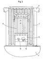
- the Fig. 2 shows the arrangement of the Injektorbox in the wall panel 7 of the upper vessel in the view A of Fig. 1 , It is clear the formation of the roof part 9 as a roof panel.
- the Injektorbox is a complete unit in the wall panel. 7 built-in. Wall panel 7 and injector box are hung together in the water distributor 6 of the upper vessel 5.
- the support structure 19 is shown, by means of which the injector box is suspended in the water distributor 6 of the upper vessel.
- the supporting structure 19 comprises two parallel spaced plates 20 projecting into the oven, stiffened with each other by means of two horizontally extending plates (not shown).
- the side plates 20 and feet 21 of the sheets are welded to the lower vessel 3 of the furnace.
- the support construction plates 20 are inserted with corresponding recesses 22 to the horizontal tubes of the water distributor 6 and welded.
- the bottom part 8 is attached to the lower vessel 3 via a releasable bolt connection 23 and on the other to the support structure 19.
- the roof part 9 is connected via wedge joints 24 with the support structure 19.
- the side walls of the injector box are fastened by screw connections to the side panels 20 of the supporting structure.
Landscapes
- Engineering & Computer Science (AREA)
- Mechanical Engineering (AREA)
- General Engineering & Computer Science (AREA)
- Chemical & Material Sciences (AREA)
- Combustion & Propulsion (AREA)
- Manufacturing & Machinery (AREA)
- Materials Engineering (AREA)
- Metallurgy (AREA)
- Organic Chemistry (AREA)
- Vertical, Hearth, Or Arc Furnaces (AREA)
- Gasification And Melting Of Waste (AREA)
- Feeding, Discharge, Calcimining, Fusing, And Gas-Generation Devices (AREA)
Description
- Die Erfindung betrifft eine Vorrichtung zur Aufnahme mindestens eines Injektors, mit dem Medien, wie Sauerstoff und/oder kohlenhaltige Brennstoffe, in einen Schmelzofen, insbesondere einen Elektrolichtbogenofen, eingebracht werden. Hierbei ist der jeweilige Injektor mittels der Aufnahmevorrichtung geschützt an oder in der Ofenwand des Schmelzofens angeordnet.
- Es ist bekannt, in Elektrolichtbogenöfen bei der Herstellung von Stahl Sauerstoff und Kohle in den Ofenraum einzubringen. Dies geschieht üblicherweise mittels Lanzen durch die Schlackentür oder auch mittels in das Wandpanel des Obergefäßes eingebauter Module. Der Einsatz von Türlanzen bedeutet einen Energieverlust durch Öffnen der Schlackentür. Der Einsatz von Modulen in das Obergefäß bedingt einen großen Abstand zum Stahlbad, verbunden mit einem hohen Verbrauch von Sauerstoff und Kohle. Aufgrund des großen Strahlweges ist zudem der Verschleiss des Feuerfest-Materials relativ hoch.
- Um den Abstand zum Stahlbad zu verringern, ist in der
US 6,289,035 B1 vorgeschlagen worden, den Injektor in einem Befestigungsblock an dem Oberteil eines Elektrolichtbogenofen zu befestigen und somit den Positionierungsort mehr in den Ofenraum zu verschieben. Der bekannte Befestigungsblock ist von seiner Grundkonstruktion einstückig und besteht aus einem eckigen Block aus Gusseisen. Ein solcher Block wird mit seiner Unterseite auf dem Ofenunterteil positioniert und zwar auf einer Stufe zum Ofenoberteil, die sich durch die Auskleidung des Unterteils des Ofens mit Feuerfestmaterial ergibt. In den Befestigungsblock ist eine Öffnung für den jeweiligen Injektor eingegossen, der den Positionierungswinkel des Injektors vorgibt. Der Injektor ragt aus dem Block soweit hervor, dass das darunter angeordnete Feuerfest-Material nicht im Strahlwinkel des Injektors liegt. Im Austrittsbereich des Injektors umfasst der Block eine Ausnehmung, in die ein mediumdurchflossenes Kühlpanel eingesetzt ist, das ebenfalls aus Gusseisen oder aus Kupfer besteht. Der obere Teil des massiven Blocks ist als schräges Vordach mit Nuten ausgebildet, die Schlacketeile zurückhalten sollen, um so eine Schutzschicht für den einem hohen Verschleiss ausgesetzten Block zu bilden. -
GB-A-2 280 501 - Ausgehend hiervon liegt der Erfindung die Aufgabe zugrunde, eine solche Vorrichtung zur Aufnahme eines Injektors dahingehend weiterzubilden, dass er hinsichtlich seiner Anordnung im Ofen variabler und die Wartung des einem hohen Verschleiss unterliegenden Bauteils einfacher wird.
- Diese Aufgabe wird durch Vorrichtungen mit den Merkmalen des Anspruchs 1 gelöst. Vorteilhafte Weiterentwicklungen sind in den Unteransprüchen beschrieben.
- Kerngedanke der Erfindung ist, dass die Aufnahmevorrichtung, nachfolgend als Injektorbox bezeichnet, nicht wie im Stand der Technik einteilig als Block, sondern mehrteilig ausgebildet ist, d.h. aus mehreren Einzelteilen besteht.
- Die Injektorbox umfasst hierbei einen unteren Bodenteil, einem oberen Dachteil und Seitenwände. Diese vier Bauteile sind jeweils unabhängig und derart miteinander verbunden, dass sie jeweils separat voneinander auswechselbar sind. Sollte es zum Beispiel durch den Chargiervorgang von Schrott oder Zusätzen in den Schmelzofen oder beim Betrieb zu Beschädigungen der Injektorbox gekommen sein, brauchen nur die beschädigten Teile ausgewechselt werden. Beispielsweise kann dann ein beschädigtes oder verschlissenes Dachteil ohne Ausbau des Bodenteils und der Seitenwände ersetzt werden.
- Die Injektorbox kann als komplett vormontierte Einheit an die Ofenwand oder in ein Wandpanel eingebaut werden. Die Injektorbox erlaubt zudem, dass die jeweiligen Injektoren sich von der Schmelzofenaußenseite bzw. Gefäßaußenseite ein- und ausbauen lassen.
- Vorzugsweise wird diese module Aufbauweise durch eine Tragkonstruktion erreicht, an der die Bestandteile der Injektorbox angeordnet sind.
- Das Bodenteil bzw. die Grundplatte ist vorzugsweise aus einer massiven Kupferplatte gefertigt, die wärmetechnische Vorteile besitzt. Am Bodenteil sind die Injektoren in Aufnahmen, beispielsweise in Flanschanschlüssen, befestigt.
- Das obere Dachteil wird vorzugsweise aus Stahl gefertigt, um evtl. Beschädigungen durch das Chargieren vorzubeugen. Nach einer besonders vorteilhaften Variante ist das Dachteil als Dachpanel aus einer Rohr-Rohr-Konstruktion ausgebildet mit zur Ofenwand geneigt und in Richtung Ofenmitte verlaufenden Rohren, um das Rutschen des Schrotts bzw. des Chargiermaterial zu unterstützen. Auftreffendes Chargiergut kann somit besser abgewiesen werden. Das Dachteil kann nach einer anderen Ausführungsform auch als wassergekühlte Platte ausgebildet sein.
- Die Seitenwände können aus massiven Kupferplatten oder aus Stahlplatten hergestellt sein. Sie weisen vorzugsweise an ihrer Außenseite Nuten zur besseren Anhaftung von Schlacke und damit aus Schutzgründen auf.
- Alle Teile sind vorzugsweise wassergekühlt und zwar insbesondere jeweils unabhängig mit einem separaten Kühlkreislauf. Die Kühlwasserversorgung erfolgt aus dem Wasserverteiler des Obergefäßes. Im Falle der Ausbildung als massive Kupfer- oder Stahlplatte sind Bohrungen oder Kanäle in die Platte eingebracht, die vom Kühlwasser durchflossen werden.
- Wie oben ausgeführt, ist die Injektorbox am Obergefäß des Schmelzofens mittels einer Tragkonstruktion befestigt. Wandpanel und Injektorbox werden gemeinsam in den Wasserverteiler des Obergefäßes eingehängt. Die Tragkonstruktion wird an den Wasserverteiler des Obergefäßes verschweißt und stützt sich ggfs. auf dem Unterteil des Ofens ab. Somit sind Lageänderungen, welche sich dadurch ergeben könnten, wenn die Injektorbox wie beim Stand der Technik auf den Rand der Ausmauerung gestellt würde, die in ihrer Höhe variieren kann, ausgeschlossen. Es empfiehlt sich, dass das Dachteil bzw. das Dachpanel über eine Keilverbindung mit dieser Tragkonstruktion lösbar verbunden ist, um das Dachpanel im Falle einer Beschädigung leicht entkoppeln und wechseln zu können.
- Das Dachteil kann mit den Seitenwänden abschließen. Es empfiehlt sich, dass das Dachteil seitlich über die Seitenwände übersteht. Damit können Beschädigungen der Seitenwände, zum Beispiel beim Chargieren, verringert werden.
- Durch die Injektorbox wird der jeweilige Injektor näher an die Schmelze positioniert. Durch die gewählte Anordnung werden die Strahllängen der einzusetzenden Medien zur Badoberfläche (bzw. zur Schaumschlacke) verkürzt. Die Einbaulage des jeweiligen Injektors wird vorteilhafterweise so gewählt, dass der Injektor bzw. Teil von diesem nicht über das Bodenteil hinausragen, sondern der Strahl durch eine entsprechende Öffnung im Bodenteil in Richtung Schmelze gerichtet ist. Mögliche Beschädigungen des Injektorkopfes werden somit vermieden.
- Neben den Vorteilen von kurzen Strahllängen für beispielsweise die Sauerstoff- und Kohlenstoffeinblasung, neben einem geringeren Verbrauch von Sauerstoff und Kohlenstoff durch eine optimale nahe Positionierung zum Stahlbad, einer Optimierung der Schaumschlackenbildung durch effektives Einbringen von Sauerstoff und Kohlenstoff und kürzeren Einschaltzeit für die Injektoren zeigt die vorgeschlagene mehrteilige Injektorbox den Vorteil einer einfachen Montage und Demontage durch den Einbau im Wandpanel auf. Die Injektorbox ist wartungsfreundlich, weil sie modulweise ersetzt werden kann und weil sie von der Ofenaußenseite erreichbar ist. Aufgrund der Ausbildung der Bodenplatte mit Aufnahmen können wahlweise ein oder zwei oder mehrere Injektoren eingebaut werden.
- Aufgrund der Tragkonstruktion für die Injektorbox und der vorgeschlagenen Positionierung der Injektoren in der Box wird erreicht, dass die Strahlgänge nicht auf das Feuerfest-Material gerichtet sind, so dass dieses weniger stark verschleisst. Mittels der Tragkonstruktion kann die Injektorbox mit ausreichendem Abstand zur Feuerfest-Material der Ausmauerung des unteren Ofens positioniert werden. Insgesamt wird die Produktivität und die Betriebssicherheit des Schmelzofen erhöht. Die Wartungskosten und die Herstellungskosten für die Injektorenboxen werden reduziert.
- Die Injektorbox findet insbesondere Einsatz im Elektrolichtbogenofen für die Erzeugung von Schaumschlacken bei der Produktion von Kohlenstoffstahl.
- Weitere Einzelheiten und Vorteile der Erfindung ergeben sich aus den Unteransprüchen und aus der nachfolgenden Beschreibung, in der die in den Figuren dargestellten Ausführungsformen der Erfindung näher erläutert werden. Es zeigen:
- Fig. 1
- einen Längsschnitt einer an der Ofenwand angeordneten Injektorbox;
- Fig. 2
- die Ansicht in Richtung A der
Fig. 1 auf die in den Ofenraum weisende Seite der Injektorbox; - Fig. 3
- einen Längsschnitt der Injektorbox mit Tragkonstruktion.
-
Fig. 1 zeigt die Aufnahmevorrichtung 1 nach der Erfindung, nachfolgend Injektorbox genannt, die an der Ofenwand 2 eines Schmelzofens, hier eines Elektrolichtbogenofens, angeordnet ist. Der Schmelzofen besteht zum einen aus einem Untergefäß 3, das über die Höhe des Schmelzbades bzw. Stahlbades hinaus bis zur Höhe der Schaumschlacke mit einer Feuerfest-Auskleidung 4 versehen ist. Zum anderen besteht der Schmelzofen aus dem Obergefäß 5 mit einer Rohr-Wandkonstruktion, die eine Rohrkonstruktion zur Wasserverteilung (Wasserverteiler 6) und ein Wandpanel 7 umfasst. - Die Injektorbox ist mehrteilig aufgebaut und setzt sich aus einem Bodenteil 8, einem Dachteil 9 und zwei Seitenwänden 10, 11 (verdeckt) zusammen. Bodenteil 8, Dachteil 9 und die beiden Seitenwände 10, 11 sind lösbar miteinander verbunden.
- Das Dachteil 9 ist ebenso wie das Wandpanel 7 als Panel bzw. Rohrkonstruktion ausgebildet, wobei die wasserdurchflossenen Rohre 12 bzw. Rohrleitungen des Dachpanels mäandrierend nebeneinander angeordnet sind (vgl.
Fig. 2 ). Das Dachpanel ragt schräg vorspringend in den Ofenraum hinein. Den Boden bildet das sich ebenfalls in den Ofenraum ragende Bodenteil 8 bzw. eine massive Bodenplatte, die mit dem Dachpanel abschließt und sich rückseitig an dem Untergefäß abstützt. In einem verstärkten Plattenbereich 13 sind Durchlassöffnungen 14, 15 bzw. Aufnahmen für ― bei diesem Ausführungsbeispiel ― zwei Injektoren 16, 17 für Sauerstoff und Kohlenstoff ― eingebracht, deren Injektorkopf 18 mit der Durchlassöffnung 14, 15 abschließt. Aufgrund der in den Ofenraum hineinragenden Konstruktion der Injektorbox können die Injektoren 16, 17 näher am Stahlbad-Niveau bzw. Schaumschlackenniveau angeordnet werden, hier durch den Abstand "X" gekennzeichnet. Der Abstand "Y" verdeutlicht, dass der Injektorkopf 18 entfernt vom Feuerfest-Material bzw. der Auskleidung 4 angeordnet ist, so dass Verschleisserscheinungen des Feuerfest-Materials reduziert werden. - Die
Fig. 2 zeigt die Anordnung der Injektorbox in dem Wandpanel 7 des Obergefäßes in der Ansicht A derFig. 1 . Es wird die Ausbildung des Dachteils 9 als Dachpanel deutlich. Die Injektorbox wird als komplette Einheit in das Wandpanel 7 eingebaut. Wandpanel 7 und Injektorbox werden gemeinsam in den Wasserverteiler 6 des Obergefäßes 5 eingehängt. - Mit Hilfe der
Fig. 3 wird die Tragkonstruktion 19 gezeigt, mit deren Hilfe die Injektorbox in den Wasserverteiler 6 des Obergefäßes eingehängt wird. Die Tragkonstruktion 19 umfasst zwei in den Ofen ragende parallel beabstandete Bleche 20, die untereinander mittels zwei horizontal verlaufenden Blechen (nicht gezeigt) versteift sind. Die seitlichen Bleche 20 bzw. Füße 21 der Bleche sind am Untergefäß 3 des Ofens angeschweißt. Die Tragkonstruktions-Bleche 20 sind mit entsprechenden Ausnehmungen 22 an die horizontalen Rohre des Wasserverteilers 6 gesteckt und verschweißt. Das Bodenteil 8 ist zum einen an dem Untergefäß 3 über eine lösbare Bolzenverbindung 23 und zum anderen an der Tragkonstruktion 19 befestigt. Das Dachteil 9 wird über Keilverbindungen 24 mit der Tragkonstruktion 19 verbunden. Die Seitenwände der l'njektorbox sind über Schraubverbindungen an den Seitenblechen 20 der Tragkonstruktion befestigt. - Mittels dieser Tragkonstruktion wird erreicht, dass die Bauteile der Injektorbox jeweils separat voneinander auswechselbar sind, ohne die gesamte Injektorbox austauschen zu müssen.
-
- 1
- Aufnahmevorrichtung oder Injektorbox
- 2
- Ofenwand
- 3
- Untergefäß
- 4
- Feuerfest-Auskleidung
- 5
- Obergefäß
- 6
- Wasserverteiler Obergefäß
- 7
- Wandpanel
- 8
- Bodenteil
- 9
- Dachteil
- 10
- Seitenwand
- 11
- Seitenwand
- 12
- Rohre des Dachteils
- 13
- verstärkter Plattenbereich des Bodenteils
- 14
- Durchlassöffnung bzw. Aufnahme für Injektor
- 15
- Durchlassöffnung bzw. Aufnahme für Injektor
- 16
- Sauerstoff-Injektor
- 17
- Kohlenstoff-Injektor
- 18
- Injektorkopf
- 19
- Tragkonstruktion für die Injektorbox
- 20
- Seitenbleche der Tragkonstruktion
- 21
- Füße der Seitenbleche
- 22
- Ausnehmungen der Seitenbleche
- 23
- Bolzenverbindung
- 24
- Keilverbindung
Claims (11)
- Vorrichtung (1) zur Aufnahme mindestens eines Injektors (15, 16), mit dem Medien, wie Sauerstoff und/oder kohlenhaltige Brennstoffe, in einen Schmelzofen, insbesondere einen Elektrolichtbogenofen, eingebracht werden, wobei mittels der Aufnahmevorrichtung (1) der jeweilige Injektor (15, 16) geschützt an oder in der Ofenwand (2) des Schmelzofens angeordnet ist,
dadurch gekennzeichnet,
dass diese Aufnahmevorrichtung (1) mehrteilig ausgebildet ist mit einem unteren Bodenteil (8), einem oberen Dachteil (9) und Seitenwänden (10, 11), die separat voneinander auswechselbar sind. - Vorrichtung nach Anspruch 1,
dadurch gekennzeichnet,
dass das Bodenteil (8) aus einer massiven Kupferplatte gefertigt ist. - Vorrichtung nach Anspruch 1 oder 2,
dadurch gekennzeichnet,
dass die Seitenwände (10, 11) aus massiven Kupferplatten oder Stahlplatten gefertigt sind. - Vorrichtung nach einem der Ansprüche 1 bis 3,
dadurch gekennzeichnet,
dass das Dachteil (9) als Dachpanel oder als Platte ausgebildet ist. - Vorrichtung nach Anspruch 4,
dadurch gekennzeichnet,
dass das Dachpanel als Rohr-an-Rohr-Konstruktion aus Stahl mit zur Ofenwand geneigt und in Richtung Ofenmitte verlaufenden Rohren (12) ausgebildet ist. - Vorrichtung nach einem der Ansprüche 1 bis 5,
dadurch gekennzeichnet,
dass das Bodenteil (8) und/oder das Dachteil (9) und/oder die Seitenwände (10, 11) gekühlt, insbesondere wassergekühlt, sind. - Vorrichtung nach Anspruch 6,
dadurch gekennzeichnet,
dass dem Bodenteil (8), dem Dachteil (9) und den Seitenwänden (10, 11) separate Kühlkreisläufe zugeordnet sind. - Vorrichtung nach einem der Ansprüche 1 bis 7,
dadurch gekennzeichnet,
dass das untere Bodenteil (8), das obere Dachteil (9) und die Seitenwände (10, 11) lösbar an einer gemeinsamen Tragkonstruktion (19) befestigt sind, die am Obergefäß (5) angeordnet ist. - Vorrichtung nach Anspruch 8,
dadurch gekennzeichnet,
dass das Dachteil (9) über mindestens eine Keilverbindung (24) mit der Tragkonstruktion (19) verbunden ist. - Vorrichtung nach einem der Ansprüche 4 bis 7,
dadurch gekennzeichnet,
dass das Dachteil (9) seitlich über die Seitenwände als Schutz vor Beschädigungen übersteht. - Vorrichtung nach einem der Ansprüche 1 bis 10,
dadurch gekennzeichnet,
dass in dem Bodenteil (8) eine Durchlassöffnung (14, 15) für den jeweiligen Injektor (16, 17) vorgesehen ist und darin der jeweilige Injektor (16, 17) so positioniert ist, dass der Injektorkopf (18) nicht aus dem Bodenteil (8) herausragt.
Applications Claiming Priority (2)
| Application Number | Priority Date | Filing Date | Title |
|---|---|---|---|
| DE10361753A DE10361753A1 (de) | 2003-12-29 | 2003-12-29 | Aufnahmevorrichtung für Injektoren |
| DE10361753 | 2003-12-29 |
Publications (3)
| Publication Number | Publication Date |
|---|---|
| EP1553192A2 EP1553192A2 (de) | 2005-07-13 |
| EP1553192A3 EP1553192A3 (de) | 2007-09-26 |
| EP1553192B1 true EP1553192B1 (de) | 2010-07-28 |
Family
ID=34585313
Family Applications (1)
| Application Number | Title | Priority Date | Filing Date |
|---|---|---|---|
| EP04028237A Expired - Lifetime EP1553192B1 (de) | 2003-12-29 | 2004-11-29 | Aufnahmevorrichtung für Injektoren in einem Schmelzofen |
Country Status (3)
| Country | Link |
|---|---|
| EP (1) | EP1553192B1 (de) |
| AT (1) | ATE475850T1 (de) |
| DE (2) | DE10361753A1 (de) |
Families Citing this family (8)
| Publication number | Priority date | Publication date | Assignee | Title |
|---|---|---|---|---|
| US7704445B2 (en) * | 2005-06-29 | 2010-04-27 | Process Technology International, Inc. | Systems and methods for accessing a furnace melt |
| DE102005034309A1 (de) | 2005-07-01 | 2007-01-04 | Sms Demag Ag | Wandelement für einen metallurgischen Ofen |
| US7951325B2 (en) | 2006-05-17 | 2011-05-31 | Air Liquide Advanced Technologies U.S. Llc | Methods of implementing a water-cooling system into a burner panel and related apparatuses |
| US7824604B2 (en) | 2006-05-17 | 2010-11-02 | Air Liquide Advanced Technologies U.S. Llc | Methods of implementing a water-cooling system into a burner panel and related apparatuses |
| BRPI0711913B1 (pt) | 2006-05-18 | 2015-08-18 | Technological Resouces Pty Ltd | Vaso de fusão redutora direta e elemento de resfriador para localização em uma soleira revestida de refratário de um vaso de fusão redutora direta |
| DE102008032523A1 (de) | 2008-07-10 | 2010-01-14 | Sms Siemag Aktiengesellschaft | Halterung für einen Injektor und Verfahren zu seinem Betrieb |
| DE102017126317A1 (de) | 2017-11-09 | 2019-05-09 | Sms Group Gmbh | Aufnahmevorrichtung für Behandlungsvorrichtungen für metallurgische Gefäße |
| DE102018220242A1 (de) | 2018-03-08 | 2019-09-12 | Sms Group Gmbh | Verfahren zum Anordnen eines Sauerstoffinjektors an einem metallurgischen Schmelzaggregat sowie metallurgisches Schmelzaggregat |
Family Cites Families (3)
| Publication number | Priority date | Publication date | Assignee | Title |
|---|---|---|---|---|
| GB734077A (en) * | 1951-08-27 | 1955-07-27 | Fuel Firing Ltd | Improvements relating to burners |
| GB2280501B (en) * | 1993-07-30 | 1996-10-23 | Co Steel Sheerness Plc | Burner mounting device |
| US6289035B1 (en) * | 2000-02-10 | 2001-09-11 | Valery G. Shver | Mounting arrangement for auxiliary burner or lance |
-
2003
- 2003-12-29 DE DE10361753A patent/DE10361753A1/de not_active Withdrawn
-
2004
- 2004-11-29 EP EP04028237A patent/EP1553192B1/de not_active Expired - Lifetime
- 2004-11-29 DE DE502004011440T patent/DE502004011440D1/de not_active Expired - Lifetime
- 2004-11-29 AT AT04028237T patent/ATE475850T1/de active
Also Published As
| Publication number | Publication date |
|---|---|
| EP1553192A3 (de) | 2007-09-26 |
| EP1553192A2 (de) | 2005-07-13 |
| DE502004011440D1 (de) | 2010-09-09 |
| DE10361753A1 (de) | 2005-07-28 |
| ATE475850T1 (de) | 2010-08-15 |
Similar Documents
| Publication | Publication Date | Title |
|---|---|---|
| EP0731180B1 (de) | Kühlplatte für Schachtöfen | |
| EP0031160B1 (de) | Metallurgisches Schmelz- und Frischaggregat | |
| DE60115191T2 (de) | Montageanordnung für zusatzbrenner oder thermische lanze | |
| DE29611704U1 (de) | Kühlplatte für metallurgische Öfen | |
| DE69602871T2 (de) | Vorrichtung zur Herstellung von Roheisen durch Direktreduktion | |
| EP1553192B1 (de) | Aufnahmevorrichtung für Injektoren in einem Schmelzofen | |
| EP0918092B1 (de) | Kühlelemente für Schachtöfen | |
| EP0048007B1 (de) | Metallurgisches Schmelzaggregat mit einer schwenkbaren Düse bzw. einem schwenkbaren Brenner | |
| EP0487494B1 (de) | Anlage zur Herstellung von flüssigen Metallen | |
| DE69802427T2 (de) | Feuerfeste mauerstruktur sowie aus diese bestehendes metallurgisches gefäss und verfahren zur verwendung dieser feuerfesten mauerstruktur | |
| EP1218549B1 (de) | Metallurgischer ofen mit kupferkühlplatten | |
| DE69117782T2 (de) | Herdboden für Gleichstrom-Lichtbogenöfen | |
| EP1381817B1 (de) | Kühlelement zur kühlung eines metallurgischen ofens | |
| DE3153040C2 (de) | Plattenkühler für Verhüttungsöfen, insbesondere Hochöfen | |
| EP0060239B1 (de) | Rinne für eine Metallschmelze | |
| DE2722681A1 (de) | Metallurgischer ofen | |
| EP0825383B1 (de) | Rostplatte | |
| EP2300768B1 (de) | Halterung für einen injektor und verfahren zu seinem betrieb | |
| EP0267197B1 (de) | Schmelz- und warmhalteofen | |
| EP0085461A1 (de) | Flüssigkeitsgekühlte Gefässwände für Lichtbogenöfen | |
| DE29616509U1 (de) | Wandkühlelement für Schachtöfen | |
| EP2255140B1 (de) | Kühlelement zur kühlung der feuerfesten auskleidung eines metallurgischen ofens | |
| DE19545984A1 (de) | Kühlplatte für Schmelzöfen | |
| AT410717B (de) | Kühlplatte mit verstärkungsteil | |
| DE3321118C2 (de) | Brenner für Schmelzöfen |
Legal Events
| Date | Code | Title | Description |
|---|---|---|---|
| PUAI | Public reference made under article 153(3) epc to a published international application that has entered the european phase |
Free format text: ORIGINAL CODE: 0009012 |
|
| 17P | Request for examination filed |
Effective date: 20041207 |
|
| AK | Designated contracting states |
Kind code of ref document: A2 Designated state(s): AT BE BG CH CY CZ DE DK EE ES FI FR GB GR HU IE IS IT LI LU MC NL PL PT RO SE SI SK TR |
|
| AX | Request for extension of the european patent |
Extension state: AL HR LT LV MK YU |
|
| PUAL | Search report despatched |
Free format text: ORIGINAL CODE: 0009013 |
|
| AK | Designated contracting states |
Kind code of ref document: A3 Designated state(s): AT BE BG CH CY CZ DE DK EE ES FI FR GB GR HU IE IS IT LI LU MC NL PL PT RO SE SI SK TR |
|
| AX | Request for extension of the european patent |
Extension state: AL HR LT LV MK YU |
|
| AKX | Designation fees paid |
Designated state(s): AT BE BG CH CY CZ DE DK EE ES FI FR GB GR HU IE IS IT LI LU MC NL PL PT RO SE SI SK TR |
|
| 17Q | First examination report despatched |
Effective date: 20080804 |
|
| RAP1 | Party data changed (applicant data changed or rights of an application transferred) |
Owner name: SMS SIEMAG AG |
|
| GRAP | Despatch of communication of intention to grant a patent |
Free format text: ORIGINAL CODE: EPIDOSNIGR1 |
|
| RIC1 | Information provided on ipc code assigned before grant |
Ipc: F27B 3/20 20060101AFI20100219BHEP Ipc: F27D 1/12 20060101ALI20100219BHEP Ipc: F27B 3/22 20060101ALI20100219BHEP |
|
| GRAS | Grant fee paid |
Free format text: ORIGINAL CODE: EPIDOSNIGR3 |
|
| GRAA | (expected) grant |
Free format text: ORIGINAL CODE: 0009210 |
|
| AK | Designated contracting states |
Kind code of ref document: B1 Designated state(s): AT BE BG CH CY CZ DE DK EE ES FI FR GB GR HU IE IS IT LI LU MC NL PL PT RO SE SI SK TR |
|
| REG | Reference to a national code |
Ref country code: GB Ref legal event code: FG4D Free format text: NOT ENGLISH |
|
| REG | Reference to a national code |
Ref country code: CH Ref legal event code: EP |
|
| REG | Reference to a national code |
Ref country code: IE Ref legal event code: FG4D Free format text: LANGUAGE OF EP DOCUMENT: GERMAN |
|
| REF | Corresponds to: |
Ref document number: 502004011440 Country of ref document: DE Date of ref document: 20100909 Kind code of ref document: P |
|
| REG | Reference to a national code |
Ref country code: NL Ref legal event code: VDEP Effective date: 20100728 |
|
| PG25 | Lapsed in a contracting state [announced via postgrant information from national office to epo] |
Ref country code: FI Free format text: LAPSE BECAUSE OF FAILURE TO SUBMIT A TRANSLATION OF THE DESCRIPTION OR TO PAY THE FEE WITHIN THE PRESCRIBED TIME-LIMIT Effective date: 20100728 Ref country code: NL Free format text: LAPSE BECAUSE OF FAILURE TO SUBMIT A TRANSLATION OF THE DESCRIPTION OR TO PAY THE FEE WITHIN THE PRESCRIBED TIME-LIMIT Effective date: 20100728 |
|
| PG25 | Lapsed in a contracting state [announced via postgrant information from national office to epo] |
Ref country code: PT Free format text: LAPSE BECAUSE OF FAILURE TO SUBMIT A TRANSLATION OF THE DESCRIPTION OR TO PAY THE FEE WITHIN THE PRESCRIBED TIME-LIMIT Effective date: 20101129 Ref country code: SI Free format text: LAPSE BECAUSE OF FAILURE TO SUBMIT A TRANSLATION OF THE DESCRIPTION OR TO PAY THE FEE WITHIN THE PRESCRIBED TIME-LIMIT Effective date: 20100728 Ref country code: PL Free format text: LAPSE BECAUSE OF FAILURE TO SUBMIT A TRANSLATION OF THE DESCRIPTION OR TO PAY THE FEE WITHIN THE PRESCRIBED TIME-LIMIT Effective date: 20100728 Ref country code: IS Free format text: LAPSE BECAUSE OF FAILURE TO SUBMIT A TRANSLATION OF THE DESCRIPTION OR TO PAY THE FEE WITHIN THE PRESCRIBED TIME-LIMIT Effective date: 20101128 Ref country code: CY Free format text: LAPSE BECAUSE OF FAILURE TO SUBMIT A TRANSLATION OF THE DESCRIPTION OR TO PAY THE FEE WITHIN THE PRESCRIBED TIME-LIMIT Effective date: 20100728 Ref country code: BG Free format text: LAPSE BECAUSE OF FAILURE TO SUBMIT A TRANSLATION OF THE DESCRIPTION OR TO PAY THE FEE WITHIN THE PRESCRIBED TIME-LIMIT Effective date: 20101028 |
|
| REG | Reference to a national code |
Ref country code: IE Ref legal event code: FD4D |
|
| PG25 | Lapsed in a contracting state [announced via postgrant information from national office to epo] |
Ref country code: SE Free format text: LAPSE BECAUSE OF FAILURE TO SUBMIT A TRANSLATION OF THE DESCRIPTION OR TO PAY THE FEE WITHIN THE PRESCRIBED TIME-LIMIT Effective date: 20100728 Ref country code: GR Free format text: LAPSE BECAUSE OF FAILURE TO SUBMIT A TRANSLATION OF THE DESCRIPTION OR TO PAY THE FEE WITHIN THE PRESCRIBED TIME-LIMIT Effective date: 20101029 |
|
| PLBI | Opposition filed |
Free format text: ORIGINAL CODE: 0009260 |
|
| PG25 | Lapsed in a contracting state [announced via postgrant information from national office to epo] |
Ref country code: IE Free format text: LAPSE BECAUSE OF FAILURE TO SUBMIT A TRANSLATION OF THE DESCRIPTION OR TO PAY THE FEE WITHIN THE PRESCRIBED TIME-LIMIT Effective date: 20100728 Ref country code: DK Free format text: LAPSE BECAUSE OF FAILURE TO SUBMIT A TRANSLATION OF THE DESCRIPTION OR TO PAY THE FEE WITHIN THE PRESCRIBED TIME-LIMIT Effective date: 20100728 |
|
| 26 | Opposition filed |
Opponent name: SIEMENS AKTIENGESELLSCHAFT Effective date: 20110418 |
|
| PLAX | Notice of opposition and request to file observation + time limit sent |
Free format text: ORIGINAL CODE: EPIDOSNOBS2 |
|
| BERE | Be: lapsed |
Owner name: SMS SIEMAG AG Effective date: 20101130 |
|
| PG25 | Lapsed in a contracting state [announced via postgrant information from national office to epo] |
Ref country code: RO Free format text: LAPSE BECAUSE OF FAILURE TO SUBMIT A TRANSLATION OF THE DESCRIPTION OR TO PAY THE FEE WITHIN THE PRESCRIBED TIME-LIMIT Effective date: 20100728 Ref country code: SK Free format text: LAPSE BECAUSE OF FAILURE TO SUBMIT A TRANSLATION OF THE DESCRIPTION OR TO PAY THE FEE WITHIN THE PRESCRIBED TIME-LIMIT Effective date: 20100728 Ref country code: EE Free format text: LAPSE BECAUSE OF FAILURE TO SUBMIT A TRANSLATION OF THE DESCRIPTION OR TO PAY THE FEE WITHIN THE PRESCRIBED TIME-LIMIT Effective date: 20100728 Ref country code: CZ Free format text: LAPSE BECAUSE OF FAILURE TO SUBMIT A TRANSLATION OF THE DESCRIPTION OR TO PAY THE FEE WITHIN THE PRESCRIBED TIME-LIMIT Effective date: 20100728 |
|
| PG25 | Lapsed in a contracting state [announced via postgrant information from national office to epo] |
Ref country code: ES Free format text: LAPSE BECAUSE OF FAILURE TO SUBMIT A TRANSLATION OF THE DESCRIPTION OR TO PAY THE FEE WITHIN THE PRESCRIBED TIME-LIMIT Effective date: 20101108 Ref country code: MC Free format text: LAPSE BECAUSE OF NON-PAYMENT OF DUE FEES Effective date: 20101130 |
|
| REG | Reference to a national code |
Ref country code: CH Ref legal event code: PL |
|
| REG | Reference to a national code |
Ref country code: DE Ref legal event code: R026 Ref document number: 502004011440 Country of ref document: DE Effective date: 20110418 |
|
| PG25 | Lapsed in a contracting state [announced via postgrant information from national office to epo] |
Ref country code: CH Free format text: LAPSE BECAUSE OF NON-PAYMENT OF DUE FEES Effective date: 20101130 Ref country code: LI Free format text: LAPSE BECAUSE OF NON-PAYMENT OF DUE FEES Effective date: 20101130 |
|
| REG | Reference to a national code |
Ref country code: FR Ref legal event code: ST Effective date: 20110801 |
|
| PG25 | Lapsed in a contracting state [announced via postgrant information from national office to epo] |
Ref country code: BE Free format text: LAPSE BECAUSE OF NON-PAYMENT OF DUE FEES Effective date: 20101130 |
|
| PLBB | Reply of patent proprietor to notice(s) of opposition received |
Free format text: ORIGINAL CODE: EPIDOSNOBS3 |
|
| PG25 | Lapsed in a contracting state [announced via postgrant information from national office to epo] |
Ref country code: FR Free format text: LAPSE BECAUSE OF NON-PAYMENT OF DUE FEES Effective date: 20101130 |
|
| PG25 | Lapsed in a contracting state [announced via postgrant information from national office to epo] |
Ref country code: LU Free format text: LAPSE BECAUSE OF NON-PAYMENT OF DUE FEES Effective date: 20101129 Ref country code: HU Free format text: LAPSE BECAUSE OF FAILURE TO SUBMIT A TRANSLATION OF THE DESCRIPTION OR TO PAY THE FEE WITHIN THE PRESCRIBED TIME-LIMIT Effective date: 20110129 |
|
| PG25 | Lapsed in a contracting state [announced via postgrant information from national office to epo] |
Ref country code: TR Free format text: LAPSE BECAUSE OF FAILURE TO SUBMIT A TRANSLATION OF THE DESCRIPTION OR TO PAY THE FEE WITHIN THE PRESCRIBED TIME-LIMIT Effective date: 20100728 |
|
| PLCK | Communication despatched that opposition was rejected |
Free format text: ORIGINAL CODE: EPIDOSNREJ1 |
|
| PLBN | Opposition rejected |
Free format text: ORIGINAL CODE: 0009273 |
|
| STAA | Information on the status of an ep patent application or granted ep patent |
Free format text: STATUS: OPPOSITION REJECTED |
|
| 27O | Opposition rejected |
Effective date: 20121206 |
|
| REG | Reference to a national code |
Ref country code: DE Ref legal event code: R100 Ref document number: 502004011440 Country of ref document: DE Effective date: 20121206 |
|
| P01 | Opt-out of the competence of the unified patent court (upc) registered |
Effective date: 20230707 |
|
| PGFP | Annual fee paid to national office [announced via postgrant information from national office to epo] |
Ref country code: GB Payment date: 20231123 Year of fee payment: 20 |
|
| PGFP | Annual fee paid to national office [announced via postgrant information from national office to epo] |
Ref country code: IT Payment date: 20231124 Year of fee payment: 20 Ref country code: DE Payment date: 20231121 Year of fee payment: 20 Ref country code: AT Payment date: 20231121 Year of fee payment: 20 |
|
| REG | Reference to a national code |
Ref country code: DE Ref legal event code: R071 Ref document number: 502004011440 Country of ref document: DE |
|
| REG | Reference to a national code |
Ref country code: GB Ref legal event code: PE20 Expiry date: 20241128 |
|
| REG | Reference to a national code |
Ref country code: AT Ref legal event code: MK07 Ref document number: 475850 Country of ref document: AT Kind code of ref document: T Effective date: 20241129 |
|
| PG25 | Lapsed in a contracting state [announced via postgrant information from national office to epo] |
Ref country code: GB Free format text: LAPSE BECAUSE OF EXPIRATION OF PROTECTION Effective date: 20241128 |
|
| PG25 | Lapsed in a contracting state [announced via postgrant information from national office to epo] |
Ref country code: GB Free format text: LAPSE BECAUSE OF EXPIRATION OF PROTECTION Effective date: 20241128 |