EP3483486A1 - Druckmittelversorungseinrichtung - Google Patents
Druckmittelversorungseinrichtung Download PDFInfo
- Publication number
- EP3483486A1 EP3483486A1 EP18199096.1A EP18199096A EP3483486A1 EP 3483486 A1 EP3483486 A1 EP 3483486A1 EP 18199096 A EP18199096 A EP 18199096A EP 3483486 A1 EP3483486 A1 EP 3483486A1
- Authority
- EP
- European Patent Office
- Prior art keywords
- valve
- pressure medium
- supply device
- housing
- medium supply
- Prior art date
- Legal status (The legal status is an assumption and is not a legal conclusion. Google has not performed a legal analysis and makes no representation as to the accuracy of the status listed.)
- Withdrawn
Links
- 238000009826 distribution Methods 0.000 description 14
- 238000007789 sealing Methods 0.000 description 5
- 238000003860 storage Methods 0.000 description 5
- 230000005540 biological transmission Effects 0.000 description 3
- 238000010276 construction Methods 0.000 description 2
- 238000010586 diagram Methods 0.000 description 2
- 238000004519 manufacturing process Methods 0.000 description 2
- 240000006829 Ficus sundaica Species 0.000 description 1
- 230000000903 blocking effect Effects 0.000 description 1
- 238000001514 detection method Methods 0.000 description 1
- 238000000034 method Methods 0.000 description 1
- 230000001105 regulatory effect Effects 0.000 description 1
- 238000005507 spraying Methods 0.000 description 1
Images


Classifications
-
- F—MECHANICAL ENGINEERING; LIGHTING; HEATING; WEAPONS; BLASTING
- F16—ENGINEERING ELEMENTS AND UNITS; GENERAL MEASURES FOR PRODUCING AND MAINTAINING EFFECTIVE FUNCTIONING OF MACHINES OR INSTALLATIONS; THERMAL INSULATION IN GENERAL
- F16K—VALVES; TAPS; COCKS; ACTUATING-FLOATS; DEVICES FOR VENTING OR AERATING
- F16K11/00—Multiple-way valves, e.g. mixing valves; Pipe fittings incorporating such valves
- F16K11/02—Multiple-way valves, e.g. mixing valves; Pipe fittings incorporating such valves with all movable sealing faces moving as one unit
- F16K11/06—Multiple-way valves, e.g. mixing valves; Pipe fittings incorporating such valves with all movable sealing faces moving as one unit comprising only sliding valves, i.e. sliding closure elements
- F16K11/072—Multiple-way valves, e.g. mixing valves; Pipe fittings incorporating such valves with all movable sealing faces moving as one unit comprising only sliding valves, i.e. sliding closure elements with pivoted closure members
- F16K11/074—Multiple-way valves, e.g. mixing valves; Pipe fittings incorporating such valves with all movable sealing faces moving as one unit comprising only sliding valves, i.e. sliding closure elements with pivoted closure members with flat sealing faces
- F16K11/0743—Multiple-way valves, e.g. mixing valves; Pipe fittings incorporating such valves with all movable sealing faces moving as one unit comprising only sliding valves, i.e. sliding closure elements with pivoted closure members with flat sealing faces with both the supply and the discharge passages being on one side of the closure plates
-
- B—PERFORMING OPERATIONS; TRANSPORTING
- B60—VEHICLES IN GENERAL
- B60G—VEHICLE SUSPENSION ARRANGEMENTS
- B60G17/00—Resilient suspensions having means for adjusting the spring or vibration-damper characteristics, for regulating the distance between a supporting surface and a sprung part of vehicle or for locking suspension during use to meet varying vehicular or surface conditions, e.g. due to speed or load
- B60G17/02—Spring characteristics, e.g. mechanical springs and mechanical adjusting means
- B60G17/04—Spring characteristics, e.g. mechanical springs and mechanical adjusting means fluid spring characteristics
- B60G17/052—Pneumatic spring characteristics
- B60G17/0523—Regulating distributors or valves for pneumatic springs
- B60G17/0525—Height adjusting or levelling valves
-
- B—PERFORMING OPERATIONS; TRANSPORTING
- B60—VEHICLES IN GENERAL
- B60G—VEHICLE SUSPENSION ARRANGEMENTS
- B60G99/00—Subject matter not provided for in other groups of this subclass
- B60G99/002—Suspension details of the suspension of the vehicle body on the vehicle chassis
-
- B—PERFORMING OPERATIONS; TRANSPORTING
- B62—LAND VEHICLES FOR TRAVELLING OTHERWISE THAN ON RAILS
- B62D—MOTOR VEHICLES; TRAILERS
- B62D33/00—Superstructures for load-carrying vehicles
- B62D33/06—Drivers' cabs
- B62D33/0604—Cabs insulated against vibrations or noise, e.g. with elastic suspension
- B62D33/0608—Cabs insulated against vibrations or noise, e.g. with elastic suspension pneumatic or hydraulic suspension
-
- F—MECHANICAL ENGINEERING; LIGHTING; HEATING; WEAPONS; BLASTING
- F15—FLUID-PRESSURE ACTUATORS; HYDRAULICS OR PNEUMATICS IN GENERAL
- F15B—SYSTEMS ACTING BY MEANS OF FLUIDS IN GENERAL; FLUID-PRESSURE ACTUATORS, e.g. SERVOMOTORS; DETAILS OF FLUID-PRESSURE SYSTEMS, NOT OTHERWISE PROVIDED FOR
- F15B13/00—Details of servomotor systems ; Valves for servomotor systems
- F15B13/02—Fluid distribution or supply devices characterised by their adaptation to the control of servomotors
- F15B13/06—Fluid distribution or supply devices characterised by their adaptation to the control of servomotors for use with two or more servomotors
- F15B13/07—Fluid distribution or supply devices characterised by their adaptation to the control of servomotors for use with two or more servomotors in distinct sequence
-
- F—MECHANICAL ENGINEERING; LIGHTING; HEATING; WEAPONS; BLASTING
- F16—ENGINEERING ELEMENTS AND UNITS; GENERAL MEASURES FOR PRODUCING AND MAINTAINING EFFECTIVE FUNCTIONING OF MACHINES OR INSTALLATIONS; THERMAL INSULATION IN GENERAL
- F16K—VALVES; TAPS; COCKS; ACTUATING-FLOATS; DEVICES FOR VENTING OR AERATING
- F16K11/00—Multiple-way valves, e.g. mixing valves; Pipe fittings incorporating such valves
- F16K11/10—Multiple-way valves, e.g. mixing valves; Pipe fittings incorporating such valves with two or more closure members not moving as a unit
- F16K11/20—Multiple-way valves, e.g. mixing valves; Pipe fittings incorporating such valves with two or more closure members not moving as a unit operated by separate actuating members
- F16K11/207—Multiple-way valves, e.g. mixing valves; Pipe fittings incorporating such valves with two or more closure members not moving as a unit operated by separate actuating members with two handles or actuating mechanisms at opposite sides of the housing
-
- F—MECHANICAL ENGINEERING; LIGHTING; HEATING; WEAPONS; BLASTING
- F16—ENGINEERING ELEMENTS AND UNITS; GENERAL MEASURES FOR PRODUCING AND MAINTAINING EFFECTIVE FUNCTIONING OF MACHINES OR INSTALLATIONS; THERMAL INSULATION IN GENERAL
- F16K—VALVES; TAPS; COCKS; ACTUATING-FLOATS; DEVICES FOR VENTING OR AERATING
- F16K27/00—Construction of housing; Use of materials therefor
- F16K27/04—Construction of housing; Use of materials therefor of sliding valves
- F16K27/044—Construction of housing; Use of materials therefor of sliding valves slide valves with flat obturating members
- F16K27/047—Construction of housing; Use of materials therefor of sliding valves slide valves with flat obturating members with wedge-shaped obturating members
-
- B—PERFORMING OPERATIONS; TRANSPORTING
- B60—VEHICLES IN GENERAL
- B60G—VEHICLE SUSPENSION ARRANGEMENTS
- B60G2204/00—Indexing codes related to suspensions per se or to auxiliary parts
- B60G2204/10—Mounting of suspension elements
- B60G2204/16—Mounting of vehicle body on chassis
- B60G2204/162—Cabins, e.g. for trucks, tractors
-
- B—PERFORMING OPERATIONS; TRANSPORTING
- B60—VEHICLES IN GENERAL
- B60G—VEHICLE SUSPENSION ARRANGEMENTS
- B60G2206/00—Indexing codes related to the manufacturing of suspensions: constructional features, the materials used, procedures or tools
- B60G2206/01—Constructional features of suspension elements, e.g. arms, dampers, springs
- B60G2206/011—Modular constructions
- B60G2206/0116—Integrated distribution control units with valves, accumulators, PCB's or the like
-
- B—PERFORMING OPERATIONS; TRANSPORTING
- B60—VEHICLES IN GENERAL
- B60G—VEHICLE SUSPENSION ARRANGEMENTS
- B60G2206/00—Indexing codes related to the manufacturing of suspensions: constructional features, the materials used, procedures or tools
- B60G2206/01—Constructional features of suspension elements, e.g. arms, dampers, springs
- B60G2206/90—Maintenance
- B60G2206/91—Assembly procedures
-
- F—MECHANICAL ENGINEERING; LIGHTING; HEATING; WEAPONS; BLASTING
- F15—FLUID-PRESSURE ACTUATORS; HYDRAULICS OR PNEUMATICS IN GENERAL
- F15B—SYSTEMS ACTING BY MEANS OF FLUIDS IN GENERAL; FLUID-PRESSURE ACTUATORS, e.g. SERVOMOTORS; DETAILS OF FLUID-PRESSURE SYSTEMS, NOT OTHERWISE PROVIDED FOR
- F15B13/00—Details of servomotor systems ; Valves for servomotor systems
- F15B13/02—Fluid distribution or supply devices characterised by their adaptation to the control of servomotors
- F15B13/04—Fluid distribution or supply devices characterised by their adaptation to the control of servomotors for use with a single servomotor
- F15B13/0401—Valve members; Fluid interconnections therefor
- F15B13/0406—Valve members; Fluid interconnections therefor for rotary valves
-
- F—MECHANICAL ENGINEERING; LIGHTING; HEATING; WEAPONS; BLASTING
- F15—FLUID-PRESSURE ACTUATORS; HYDRAULICS OR PNEUMATICS IN GENERAL
- F15B—SYSTEMS ACTING BY MEANS OF FLUIDS IN GENERAL; FLUID-PRESSURE ACTUATORS, e.g. SERVOMOTORS; DETAILS OF FLUID-PRESSURE SYSTEMS, NOT OTHERWISE PROVIDED FOR
- F15B2211/00—Circuits for servomotor systems
- F15B2211/30—Directional control
- F15B2211/305—Directional control characterised by the type of valves
- F15B2211/3056—Assemblies of multiple valves
- F15B2211/3059—Assemblies of multiple valves having multiple valves for multiple output members
-
- F—MECHANICAL ENGINEERING; LIGHTING; HEATING; WEAPONS; BLASTING
- F15—FLUID-PRESSURE ACTUATORS; HYDRAULICS OR PNEUMATICS IN GENERAL
- F15B—SYSTEMS ACTING BY MEANS OF FLUIDS IN GENERAL; FLUID-PRESSURE ACTUATORS, e.g. SERVOMOTORS; DETAILS OF FLUID-PRESSURE SYSTEMS, NOT OTHERWISE PROVIDED FOR
- F15B2211/00—Circuits for servomotor systems
- F15B2211/30—Directional control
- F15B2211/315—Directional control characterised by the connections of the valve or valves in the circuit
- F15B2211/31523—Directional control characterised by the connections of the valve or valves in the circuit being connected to a pressure source and an output member
- F15B2211/31541—Directional control characterised by the connections of the valve or valves in the circuit being connected to a pressure source and an output member having a single pressure source and multiple output members
Definitions
- the invention relates to a pressure medium supply device according to the preamble of patent claim 1.
- a pressure medium supply device for.
- a chassis or a cabin storage the individual components are supplied by different manufacturers and attached during assembly in a designated place.
- a pressure medium supply device is part of an active system, which is often offered as an equipment option. Consequently, there is a significant assembly effort between a simple passive system, such as a mechanical cab storage, and an active regulated cab storage. However, both systems often have to be mountable on a production line.
- the object of the present invention is to further develop a pressure medium supply device in order to minimize the assembly effort.
- This object is achieved in that at least two separately switchable valves are arranged in a common housing.
- the advantage is that over the simple assembly of the housing essential components of the pressure medium supply devices are mounted on the vehicle.
- the housing with the valves can be completely independently mounted and prepared, so that a quick mounting on the vehicle is possible.
- At least one connecting line between the valves extends within a wall structure of the housing.
- the assembly of the module is further simplified and increased reliability, for example because no hose can burst.
- the housing has a receptacle for a control unit.
- the electronics are not only well protected, but the connection paths to the valves are conceivably short.
- At least one valve is designed as a rotary slide valve and the housing has an axle carrier for the rotary slide valve.
- the axle is formed by a hollow profile, which in turn is connected to the wall parts. This results in a very rigid housing structure.
- both valves are designed as rotary valves and have a common axle.
- the hollow profile is simplified as a tubular body shaped.
- the housing consists of a formable material, with which the hollow profile can be carried out sufficiently accurately.
- axle is a valve carrier of the switchable valve stored.
- valve carrier is the movable component of the switchable valve.
- the valve has no further housing which accommodates the individual valve components.
- the valve carrier has several switching ranges for different valves. This makes it possible to use a standard component as a valve carrier, wherein one of the switching ranges is used for a specific valve function.
- At least one wall region of the housing forms a slide valve with the valve carrier.
- the slide valve design promotes the connection of housing-side wall areas and z.
- B. the movable valve parts by simply sliding the spool valve components to each other.
- the valve carrier has a transmission profile for an electric motor.
- the valve carrier has a receptacle with a spline for the motor shaft. Again, a simple plug connection between the electric motor and the valve carrier is sufficient.
- the housing has a receptacle for a pressure generating unit.
- the energy requirement can also be met by a relatively small compressor or a small pump, so that the space requirement can be realized.
- the receptacle has a connection channel to a pressure medium input terminal of the housing. This pressure inlet port is also used with an external pressure generator.
- the housing has two end covers. This construction promotes the production of the housing in a prototype process, eg. B. a spraying method for a plastic housing.
- the receptacle for the pressure generating unit is executed in the lid.
- the lid is easy to replace so that the case can be combined with an external or internal pressure generator.
- FIG. 12 shows an alternative diagram of an exemplary leveling system 1 with a pressure medium supply device 3, which in this embodiment comprises a pressure generating unit 5 in the form of a compressor in combination with a storage 7.
- a pressure medium supply device would be conceivable.
- the pressure medium supply device 3 is connected in the direction of a plurality of support units 9-15, for example air springs, a supply valve 17. Functionally between the supply valve 17 and the support units 9-15 is a single distribution valve 19 as part of the entire valve assembly 17; 19, which includes only the supply valve 17 and the distribution valve 19, arranged. With the distribution valve 19, at least three support units can be controlled selectively to adjust the level position, such as a vehicle cabin.
- the supply valve 17 is designed as a 3/3-way valve and has a blocking position "b" in the direction of the distribution valve 19. In addition, all other flow connections to the support units 9-15 can be blocked.
- a discharge position "c" the pressure medium for all support units 9-15 can be removed.
- the deflated air exits to the outside.
- the distribution valve 19 has a plurality of passage positions "x", “y”, “z”, in each of which a flow channel can flow through each other and in the ports "1"; “2”; “3” are blocked to the other support units 9-15.
- the distribution valve 19 and the supply valve 17 are designed as rotary valves and are actuated by an electric motor.
- Stylized transmission profiles 21; 23 on valve supports 25; 27 and electric motors 29; 31 is intended to represent the rotary valve design.
- a symbolized by a dotted line housing 33 receives the pressure medium supply means 3 at least so far that the two separately switchable supply valve 17 and the distribution valve 19 are arranged in the common housing 33.
- FIG. 2 shows the housing 33 with the components installed therein in an exploded view.
- the housing 33 may also have a receptacle 35 for a control unit 37.
- the picture 35 is clearly recognizable.
- an electrical connection 41 via which a connection between a vehicle electrical system of a vehicle and the control unit 37, here symbolized by a circuit board with connection plugs, is closed. ( Fig.2 )
- the housing 33 has two end-side lid 43; 45, via which the housing 33 is fixable to a vehicle. From two sides in each case the electric motor 29; 31 can be mounted, via a spline 47; 49 in the transmission profile 21; 23 of the respective valve carrier 25; 27 engages. Both valve supports 25; 27 take valve discs 51; 53, which with another valve disc 55; 57 as part of a wall area (s. Fig. 4 ) form a slide valve in the function of the supply valve 17 and the distribution valve 19. So that no moisture can penetrate into the housing 33, sealing rings 59; 61 between a housing ring 63 and the covers 43; 45 braced.
- FIG. 4 shows the housing 33 with a cutout in the area of the supply valve 17 and the distribution valve 19.
- wall structures 65 are shown cut, in which at least one connecting line between the two valves 17; 19 are lost ( Fig. 1 ).
- Fig. 5 refer to the connecting line 67 between the valves 17; 19 without the adjacent wall structures shows.
- a Wandungssebene connecting lines 69; 71; 73 to the support units 9-13 and in a further wall level connecting lines 75; 77 arranged to an inlet and an outlet port.
- the valve point of the inlet and the outlet connection, the valve disc 57 is fixed within the wall, which cooperates with the rotatable via the valve carrier 27 valve disc 53.
- the valve carrier 25; 27 preferably have two switching areas for receiving in each case a valve disc 51, which is provided for the supply valve 17 and a valve disc 53, which is provided for the distribution valve 19. ( Fig. 6 ). Therefore, the valve carrier 25; 27 as a standard component for both valves 17; 19 are used.
- axle carrier 85 is disclosed as part of the housing 33.
- the axle support 85 is designed as a tubular body with a support wall 87 in which the valve supports 25; 27 of the switchable valves 17; 19 are guided axially and radially.
- the two valve carrier 25; 27 are arranged in mirror image to the support wall 87. Also visible are fastening eyes 89 on the electric motors, via which a torque support on the housing 33 takes place.
- valve carrier 25 In the Fig. 6 the valve carrier 25 is shown, wherein a switching portion 83 is open, which has a zigzag-shaped seal receiver. This shift range interacts with the valve disk 53 for the distributor valve 19.
- the switching range for the supply valve 17 has an angle profile. ( Fig. 7 )
- FIG. 8A With the figure series 8A - 8C, the circuit diagram of the two valve disks 53; 57 of the distribution valve 19 are illustrated.
- Fig. 8A is the connecting line 67 to the supply valve 17 and the connecting line 69 to the support unit 9 via a sealing ring 91 connected together according to the switching position "X". All other connecting lines in the rotary valve 19 are closed. Consequently, pressure medium can be supplied to the support unit 9 or drained.
- Fig. 8b is the connecting line 67 to the supply valve 17 in turn open, however, the connecting line 71 is connected to the support unit 11.
- the connecting line 71 is connected to the support unit 11.
- the connecting line 73 is connected to the connecting line 73 for the combination of the support units 13; 15th
- the sequence of figures 9A and 9B is intended to illustrate the rotary valve function of the supply valve 17.
- the connecting line 67 is connected in the direction of the distributor valve with the connecting line 75 to the pressure medium supply device via a collecting space bounded by an annular region of the sealing ring 93 corresponding to the switching position "a".
- the Fig. 9b has the position of the valve discs 51; 55 changed over a twisting movement such that now the Connecting line 67 to the distribution valve 19 connected to the connecting line 77 for pressure medium discharge.
- this sequence of figures one can see the two ring areas whose main axis form an angle.
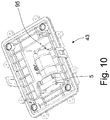
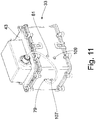
- the Figures 10 and 11 describe a further expansion stage of the housing 33, which now has a receptacle 95 for the pressure generating unit 5.
- the pressure generating unit for a vehicle cabin can be dimensioned relatively compact.
- the receptacle 95 is designed as a recess for the pressure generating unit in the lid 43.
- the receptacle 95 has a connection channel 97 to the pressure medium inlet port 79.
- the connecting channel 97 is preferably designed as a pressure hose, which can also run externally. This measure also serves the simple construction of the entire housing.
- the support units including sensors for level detection 99-103 are mounted, for example between a vehicle frame and a cabin. Thereafter, the housing 33 is attached to the already installed supply valve 17 and the distribution valve 19 to the vehicle. Possibly. can be mounted in the housing 33 and the pressure generating unit 5. The connections 67, 75; 77 between the two valves are already present within the wall areas. After mounting the housing, the support units 9-15 are connected via the lines 69-73 to the connection openings in outer wall regions of the housing 33. Furthermore, there is a signal connection between the sensors 99-103 and the housing 33 or the control unit 37 and the electrical power supply 41 for the control unit and for the electric motors.
- Leveling device 63 housing ring 3 Pressure medium supply device 65 wall structure 5 Pressure-generating unit 67 connecting line 7 Storage 69 connecting line 9 support unit 71 connecting line 11 support unit 73 connecting line 13 support unit 75 connecting line 15 support unit 77 connecting line 17 supply valve 79 Inlet port 19 distribution valve 81 Outlet port 21 transfer profile 83 switching range 23 transfer profile 85 axle 25 valve 87 retaining wall 27 valve 89 fastening eye 29 electric motor 91 sealing ring 31 electric motor 93 sealing ring 33 casing 95 admission 35 admission 97 connecting channel 37 control unit 99 sensors 39 outer wall 101 sensors 41 electrical connection 103 sensors 43 cover 105 connection openings 45 cover 107 connection openings 47 spline 109 connection openings 49 spline 51 valve discs 53 valve discs 55 valve discs 57 valve discs 59 seals 61 seals
Landscapes
- Engineering & Computer Science (AREA)
- Mechanical Engineering (AREA)
- General Engineering & Computer Science (AREA)
- Chemical & Material Sciences (AREA)
- Combustion & Propulsion (AREA)
- Transportation (AREA)
- Physics & Mathematics (AREA)
- Fluid Mechanics (AREA)
- Multiple-Way Valves (AREA)
Abstract
Description
- Die Erfindung betrifft eine Druckmittelversorgungseinrichtung gemäß dem Oberbegriff von Patentanspruch 1.
- Bei einer Druckmittelversorgungseinrichtung, z. B. für ein Fahrwerk oder eine Kabinenlagerung, werden die einzelnen Komponenten von verschiedenen Herstellern zugeliefert und bei der Montage an einem vorgesehenen Platz befestigt. Teilweise ist eine Druckmittelversorgungseinrichtung Bestandteil eines aktiven Systems, das vielfach als eine Ausstattungsoption angeboten wird. Folglich besteht ein deutlicher Montageaufwand zwischen einem einfachen passiven System, wie einer mechanischen Kabinenlagerung, und einer aktiven geregelten Kabinenlagerung. Beide Systeme müssen jedoch häufig auf einer Fertigungslinie montierbar sein.
- Die Aufgabe der vorliegenden Erfindung besteht darin, eine Druckmittelversorgungseinrichtung weiterzuentwickeln, um den Montageaufwand zu minimieren.
- Diese Aufgabe wird dadurch gelöst, dass mindestens zwei getrennt schaltbare Ventile in einem gemeinsamen Gehäuse angeordnet sind.
- Der Vorteil besteht darin, dass über die einfache Montage des Gehäuses wesentliche Komponenten der Druckmittelversorgungseinrichtungen am Fahrzeug montiert sind. Das Gehäuse mit den Ventilen kann völlig unabhängig montiert und vorbereitet werden, so dass eine schnelle Montage am Fahrzeug möglich ist.
- In weiterer vorteilhafter Ausgestaltung verläuft mindestens eine Verbindungsleitung zwischen den Ventilen innerhalb einer Wandstruktur des Gehäuses. Man kann auf Druckmittelschläuche im Gehäuse verzichten. Dadurch wird die Montage der Baugruppe nochmals vereinfacht und die Betriebssicherheit erhöht, da z.B. kein Schlauch platzen kann.
- Eine weitere Ausbaustufe des Gehäuses zeichnet sich dadurch aus, dass das Gehäuse eine Aufnahme für ein Steuergerät aufweist. Damit ist die Elektronik nicht nur bestens geschützt, sondern die Verbindungswege zu den Ventilen sind denkbar kurz.
- Im Hinblick auf eine kompakte und einfache Bauform ist mindestens ein Ventil als ein Drehschieberventil ausgeführt und das Gehäuse weist einen Achsträger für das Drehschieberventil auf. Der Achsträger wird von einem Hohlprofil gebildet, das wiederum mit den Wandungsteilen verbunden ist. Dadurch ergibt sich eine sehr steife Gehäusestruktur.
- Bevorzugt sind beide Ventile als Drehschieberventile ausgeführt und weisen einen gemeinsamen Achsträger auf. Dann ist das Hohlprofil vereinfacht als ein Rohrkörper geformt. Das Gehäuse besteht aus einem urformbaren Werkstoff, mit dem sich das Hohlprofil ausreichend exakt ausführen lässt.
- In dem der Achsträger ist ein Ventilträger des schaltbaren Ventils gelagert. Der Ventilträger stellt das bewegliche Bauteil des schaltbaren Ventils dar. Das Ventil verfügt über kein weiteres Gehäuse, das die einzelnen Ventilkomponenten aufnimmt.
- Der Ventilträger weist mehrere Schaltbereiche für verschiedene Ventile auf. Dadurch kann man ein Standardbauteil als Ventilträger verwenden, wobei für eine bestimmte Ventilfunktion eines der Schaltbereiche eingesetzt wird.
- Mindestens ein Wandungsbereich des Gehäuses bildet mit dem Ventilträger ein Schieberventil. Die Schieberventilbauweise fördert die Verbindung von gehäuseseitigen Wandbereichen und z. B. den beweglichen Ventilteilen, indem man die Schieberventilbauteile einfach aufeinander gleiten lässt.
- In weiterer vorteilhafter Ausgestaltung weist der Ventilträger ein Übertragungsprofil für einen E-Motor aufweist. Bevorzugt verfügt der Ventilträger über eine Aufnahme mit einem Keilprofil für die Motorwelle. Auch hier genügt eine einfache Steckverbindung zwischen dem E-Motor und dem Ventilträger.
- In einer weiteren Ausbaustufe weist dass das Gehäuse eine Aufnahme für ein Druckerzeugungsaggregat auf. Der Energiebedarf kann auch von einem relativ kleinen Kompressor oder einer kleinen Pumpe erfüllt werden, so dass die Bauraumanforderung realisierbar sind.
- Der Einsatz eines im Gehäuse angeordneten Druckerzeugungsaggregats soll die weitere Ausgestaltung der Verbindungsleitung im Gehäuse nicht beeinflussen. Deshalb weist die Aufnahme einen Verbindungskanal zu einem Druckmitteleingangsanschluss des Gehäuses auf. Dieser Druckmitteingangsanschluss wird auch bei einem externen Druckerzeugungsaggregat genutzt.
- Bevorzugt weist dass das Gehäuse zwei endseitige Deckel auf. Diese Bauweise fördert die Herstellung des Gehäuses in einem Urform-Prozess, z. B. eine Spritzverfahren für ein Gehäuse aus Kunststoff.
- Gemäß einem vorteilhaften Unteranspruch ist die Aufnahme für das Druckerzeugungsaggregat im Deckel ausgeführt. Der Deckel lässt sich einfach austauschen, so dass das Gehäuse mit einem externen oder mit einem internen Druckerzeugungsaggregat kombiniert werden kann.
- Anhand der folgenden Figurenbeschreibung soll die Erfindung näher erläutert werden.
- Es zeigt:
DieFigur 1 zeigt ein Ersatzschaubild eines beispielhaften Niveauregulierungssystems 1 mit einer Druckmittelversorgungseinrichtung 3, die in dieser Ausführungsform ein Druckerzeugungsaggregat 5 in Form eines Kompressors in Kombination mit einem Speicher 7 umfasst. Grundsätzlich wäre auch eine hydraulische Druckmittelversorgungseinrichtung denkbar. - Die Druckmittelversorgungseinrichtung 3 ist in Richtung einer Mehrzahl von Stützaggregaten 9-15, beispielsweise Luftfedern, ein Versorgungsventil 17 nachgeschaltet. Funktional zwischen dem Versorgungsventil 17 und den Stützaggregaten 9-15 ist ein einziges Verteilerventil 19 als Teil der gesamten Ventilanordnung 17; 19, die nur das Versorgungsventil 17 und das Verteilerventil 19 umfasst, angeordnet. Mit dem Verteilerventil 19 lassen sich mindestens drei Stützaggregate selektiv ansteuern, um die Niveaulage, z.B. einer Fahrzeugkabine einzustellen.
- Das Versorgungsventil 17 ist als ein 3/3-Wegeventil ausgeführt und verfügt über eine Sperrstellung "b" in Richtung des Verteilerventils 19. Darüber lassen sich alle weiteren Strömungsverbindungen zu den Stützaggregaten 9-15 blockieren.
- In einer Ablass-Stellung "c" kann das Druckmittel für sämtliche Stützaggregate 9-15 abgeführt werden. Bei einer Druckmittelversorgung mit Druckluft tritt die abgelassene Luft ins Freie aus.
- Das Verteilerventil 19 weist eine Mehrzahl von Durchlass-Stellungen "x", "y", "z" auf, in der jeweils ein Strömungskanal wechselseitig durchströmbar ist und in der Anschlüsse "1"; "2"; "3" zu den weiteren Stützaggregaten 9-15 blockiert sind.
- Das Verteilerventil 19 und auch das Versorgungsventil 17 sind als Drehschieberventile ausgeführt und werden elektromotorisch betätigt.
- Stilisierte Übertragungsprofile 21; 23 an Ventilträgern 25; 27 und Elektromotoren 29; 31 soll die Drehschieberbauform darstellen.
- Ein durch eine strichpunktierte Linie symbolisiertes Gehäuse 33 nimmt die Druckmittelversorgungseinrichtung 3 zumindest soweit auf, dass die beiden getrennt schaltbaren Versorgungsventil 17 und das Verteilerventil 19 in dem gemeinsamen Gehäuse 33 angeordnet sind.
- Die
Figur 2 zeigt das Gehäuse 33 mit den darin verbauten Komponenten in einer Explosionsdarstellung. Neben den beiden Ventilen 17; 19 kann das Gehäuse 33 auch eine Aufnahme 35 für ein Steuergerät 37 aufweisen. In derFigur 3 ist die Aufnahme 35 deutlich erkennbar. In einer äußeren Wandung 39 ist ein elektrischer Anschluss 41 befestigt, über den eine Verbindung zwischen einem Bordnetz eines Fahrzeugs und dem Steuergerät 37, hier symbolisiert durch eine Platine mit Anschlusssteckern, geschlossen wird. (Fig.2 ) - Aus der
Fig. 2 ist des Weiteren ersichtlich, dass das Gehäuse 33 zwei endseitige Deckel 43; 45 aufweist, über die das Gehäuse 33 an einem Fahrzeug fixierbar ist. Von zwei Seiten ist jeweils der E-Motor 29; 31 montierbar, der über ein Keilprofil 47; 49 in das Übertragungsprofil 21; 23 des jeweiligen Ventilträgers 25; 27 eingreift. Beide Ventilträger 25; 27 nehmen Ventilscheiben 51; 53 auf, die mit einer weiteren Ventilscheibe 55; 57 als Teil eines Wandungsbereichs (s.Fig. 4 ) ein Schieberventil in der Funktion des Versorgungsventils 17 und des Verteilerventils 19 bilden. Damit in das Gehäuse 33 keine Feuchtigkeit eindringen kann, werden Dichtungsringe 59; 61 zwischen einem Gehäusering 63 und den Deckeln 43; 45 verspannt. - Die
Figur 4 zeigt das Gehäuse 33 mit einem Freischnitt im Bereich des Versorgungsventils 17 und des Verteilerventils 19. Dabei sind auch Wandstrukturen 65 geschnitten dargestellt, in denen mindestens eine Verbindungsleitung zwischen den beiden Ventilen 17; 19 verlaufen (Fig. 1 ). In diesem Zusammenhang wird auf dieFig. 5 verwiesen, die die Verbindungsleitung 67 zwischen den Ventilen 17; 19 ohne die angrenzenden Wandstrukturen zeigt. In einer Wandungsebene sind Verbindungsleitungen 69; 71; 73 zu den Stützaggregaten 9 - 13 und in einer weiteren Wandungsebene Verbindungsleitungen 75; 77 zu einem Einlass- und einem Auslass-Anschluss angeordnet. Im Kontenpunkt des Einlass- und des Auslass-Anschlusses ist innerhalb der Wandung die Ventilscheibe 57 fixiert, die mit der über den Ventilträger 27 verdrehbaren Ventilscheibe 53 zusammenwirkt. - Die Ventilträger 25; 27 verfügen bevorzugt über zwei Schaltbereiche zur Aufnahme von jeweils einer Ventilscheibe 51, die für das Versorgungsventil 17 und eine Ventilscheibe 53, die für das Verteilerventil 19 vorgesehen ist. (
Fig. 6 ). Deshalb kann der Ventilträger 25; 27 als ein Standardbauteil für beide Ventile 17; 19 eingesetzt werden. - In der Zusammenschau der
Figuren 4 und7 ist ein Achsträger 85als Teil des Gehäuses 33 offenbart. Der Achsträger 85 ist als ein Rohrkörper mit einer Stützwand 87 ausgeführt, in dem die Ventilträger 25; 27 der schaltbaren Ventile 17; 19 axial und radial geführt sind. Die beiden Ventilträger 25; 27 sind spiegelbildlich zu der Stützwand 87 angeordnet. Erkennbar sind auch Befestigungsaugen 89 an den E-Motoren, über die eine Drehmomentabstützung am Gehäuse 33 erfolgt. - In der
Fig. 6 ist der Ventilträger 25 dargestellt, wobei ein Schaltbereich 83 offen ist, der eine zickzack-förmige Dichtungsaufnahme aufweist. Dieser Schaltbereich wirkt mit der Ventilscheibe 53 für das Verteilerventil 19 zusammen. Der Schaltbereich für das Versorgungsventil 17 weist ein Winkelprofil auf. (Fig. 7 ) - Mit der Figurenreihe 8A - 8C soll das Schaltbild der beiden Ventilscheiben 53; 57 des Verteilerventils 19 verdeutlicht werden. In der
Fig. 8A ist die Verbindungsleitung 67 zum Versorgungsventil 17 und die Verbindungsleitung 69 zum Stützaggregat 9 über einen Dichtungsring 91 miteinander verbunden entsprechend der Schaltstellung "X". Alle anderen Verbindungsleitungen in dem Drehschieberventil 19 sind verschlossen. Folglich kann Druckmittel zum Stützaggregat 9 zugeführt oder abgelassen werden. - In der
Fig. 8b ist die Verbindungsleitung 67 zum Versorgungsventil 17 wiederum geöffnet, jedoch die Verbindungsleitung 71 für das Stützaggregat 11 verbunden. Dafür ist die Ventilscheibe 53 im Ventilträger zur Ventilscheibe 57 in der Gehäusewandung rotatorisch verschoben. DieFig. 8C zeigt wiederum die Verbindungsleitung 67, jedoch verbunden mit der Verbindungsleitung 73 für die Kombination der Stützaggregate 13; 15. - Die Figurenfolge 9A und 9b soll die Drehschieberfunktion des Versorgungsventils 17 verdeutlichen. In der
Fig. 9A ist die Verbindungsleitung 67 in Richtung des Verteilerventils mit der Verbindungsleitung 75 zur Druckmittelversorgungseinrichtung über einen von einem Ringbereich des Dichtungsrings 93 begrenzten Sammelraum entsprechend der Schaltstellung "a" verbunden. In derFig. 9b hat sich die Position der Ventilscheiben 51; 55 über eine Verdrehbewegung derart verändert, dass nun die Verbindungsleitung 67 zum Verteilerventil 19 mit der Verbindungsleitung 77 zum Druckmittelablass verbunden. In dieser Figurenfolge kann man die beiden Ringbereiche erkennen, deren Hauptachse einen Winkel bilden. - Die
Figuren 10 und11 beschreiben eine weitere Ausbaustufe des Gehäuses 33, das nun eine Aufnahme 95 für das Druckerzeugungsaggregat 5 aufweist. Das Druckerzeugungsaggregat für eine Fahrzeugkabine kann relativ kompakt dimensioniert werden. Um ein möglichst weitgehend standardisiertes Gehäuse 33 verwenden zu können, ist die Aufnahme 95 als Vertiefung für das Druckerzeugungsaggregat im Deckel 43 ausgeführt. Die Aufnahme 95 weist einen Verbindungskanal 97 zu dem Druckmitteleinlassanschluss 79 aus. Der Verbindungskanal 97 ist bevorzugt als ein Druckschlauch ausgeführt, der auch extern verlaufen kann. Auch diese Maßnahme dient der einfachen Bauweise des gesamten Gehäuses. - Bei der Montage des Gesamtsystems werden die Stützaggregate inklusive Sensorik zur Niveauerfassung 99 - 103 montiert, beispielsweise zwischen einem Fahrzeugrahmen und einer Kabine. Danach wird das Gehäuse 33 mit dem bereits installierten Versorgungsventil 17 und dem Verteilerventil 19 an dem Fahrzeug befestigt. Ggf. kann im Gehäuse 33 auch das Druckerzeugungsaggregat 5 montiert sein. Die Verbindungen 67, 75; 77 zwischen beiden Ventilen sind bereits innerhalb der Wandungsbereiche vorhanden. Nach der Gehäusemontage werden die Stützaggregate 9-15 über die Leitungen 69 - 73 mit den Anschlussöffnungen in äußeren Wandbereichen des Gehäuses 33 verbunden. Des Weiteren besteht eine Signalverbindung zwischen den Sensoren 99 - 103 und dem Gehäuse 33 bzw. dem Steuergerät 37 und der elektrischen Leistungsversorgung 41 für das Steuergerät sowie für die E-Motoren.
Bezugszeichen 1 Niveauregulierungseinrichtung 63 Gehäusering 3 Druckmittelversorgungseinrichtung 65 Wandstruktur 5 Druckerzeugungsaggregat 67 Verbindungsleitung 7 Speicher 69 Verbindungsleitung 9 Stützaggregat 71 Verbindungsleitung 11 Stützaggregat 73 Verbindungsleitung 13 Stützaggregat 75 Verbindungsleitung 15 Stützaggregat 77 Verbindungsleitung 17 Versorgungsventil 79 Einlass-Anschluss 19 Verteilerventil 81 Auslass-Anschluss 21 Übertragungsprofil 83 Schaltbereich 23 Übertragungsprofil 85 Achsträger 25 Ventilträger 87 Stützwand 27 Ventilträger 89 Befestigungsauge 29 Elektromotor 91 Dichtungsring 31 Elektromotor 93 Dichtungsring 33 Gehäuse 95 Aufnahme 35 Aufnahme 97 Verbindungskanal 37 Steuergerät 99 Sensorik 39 äußere Wandung 101 Sensorik 41 elektrischer Anschluss 103 Sensorik 43 Deckel 105 Anschlussöffnungen 45 Deckel 107 Anschlussöffnungen 47 Keilprofil 109 Anschlussöffnungen 49 Keilprofil 51 Ventilscheiben 53 Ventilscheiben 55 Ventilscheiben 57 Ventilscheiben 59 Dichtungsringe 61 Dichtungsringe
Claims (13)
- Druckmittelversorgungseinrichtung (3), umfassend eine Anzahl von Ventilen (17; 19), die über Verbindungsleitungen (67 - 77) in die Druckmittelversorgungseinrichtung (3) eingebunden sind, dadurch gekennzeichnet, dass mindestens zwei getrennt schaltbare Ventile (17; 19) in einem gemeinsamen Gehäuse (33) angeordnet sind.
- Druckmittelversorgungseinrichtung nach Anspruch 1, dadurch gekennzeichnet, dass mindestens eine Verbindungsleitung (67) zwischen den Ventilen (17; 19) innerhalb einer Wandstruktur (65) des Gehäuses (33) verläuft.
- Druckmittelversorgungseinrichtung nach Anspruch 1, dadurch gekennzeichnet, dass das Gehäuse (33) eine Aufnahme (95) für ein Steuergerät (37) aufweist.
- Druckmittelversorgungseinrichtung nach Anspruch 1, dadurch gekennzeichnet, dass mindestens ein Ventil (17; 19) als ein Drehschieberventil ausgeführt ist und das Gehäuse (33) einen Achsträger (85) für das Drehschieberventil (17; 19) aufweist.
- Druckmittelversorgungseinrichtung nach Anspruch 4, dadurch gekennzeichnet, dass zwei Drehschieberventile (17; 19) einen gemeinsamen Achsträger (85) aufweisen.
- Druckmittelversorgungseinrichtung nach Anspruch 5, dadurch gekennzeichnet, dass der Achsträger (85) Ventilträger (25; 27) der schaltbaren Ventile (17; 19) lagert.
- Druckmittelversorgungseinrichtung nach Anspruch 6, dadurch gekennzeichnet, dass der Ventilträger (25; 27) mehrere Schaltbereiche (83) für verschiedene Ventile (17; 19) aufweist.
- Druckmittelversorgungseinrichtung nach Anspruch 4, dadurch gekennzeichnet, dass mindestens ein Wandungsbereich des Gehäuses (33) mit dem Ventilträger (25; 27) das Schieberventil (17; 19) bilden.
- Druckmittelversorgungseinrichtung nach Anspruch 6, dadurch gekennzeichnet, dass der Ventilträger (25; 27) ein Anschlussprofil (47; 49) für einen E-Motor (29; 31) aufweist.
- Druckmittelversorgungseinrichtung nach Anspruch 1, dadurch gekennzeichnet, dass das Gehäuse (33) eine Aufnahme (95) für ein Druckerzeugungsaggregat (5) aufweist.
- Druckmittelversorgungseinrichtung nach Anspruch 10, dadurch gekennzeichnet, dass die Aufnahme (95) einen Verbindungskanal (97) zu einem Druckmitteleingangsanschluss (79) des Gehäuses (33) aufweist.
- Druckmittelversorgungseinrichtung nach Anspruch 1, dadurch gekennzeichnet, dass das Gehäuse (33) zwei endseitige Deckel (43; 45) aufweist.
- Druckmittelversorgungseinrichtung nach Anspruch 11, dass die Aufnahme (95) für das Druckerzeugungsaggregat (5) im Deckel (43) ausgeführt ist.
Applications Claiming Priority (1)
| Application Number | Priority Date | Filing Date | Title |
|---|---|---|---|
| DE102017220090.1A DE102017220090A1 (de) | 2017-11-10 | 2017-11-10 | Druckmittelversorgungseinrichtung |
Publications (1)
| Publication Number | Publication Date |
|---|---|
| EP3483486A1 true EP3483486A1 (de) | 2019-05-15 |
Family
ID=63794373
Family Applications (1)
| Application Number | Title | Priority Date | Filing Date |
|---|---|---|---|
| EP18199096.1A Withdrawn EP3483486A1 (de) | 2017-11-10 | 2018-10-08 | Druckmittelversorungseinrichtung |
Country Status (3)
| Country | Link |
|---|---|
| EP (1) | EP3483486A1 (de) |
| CN (1) | CN109764016A (de) |
| DE (1) | DE102017220090A1 (de) |
Citations (6)
| Publication number | Priority date | Publication date | Assignee | Title |
|---|---|---|---|---|
| DE1217159B (de) * | 1961-12-27 | 1966-05-18 | Jottka Metallwarenfabrik Edgar | Steuerung fuer druckmittelbetaetigte Anlagen mit zwei Drehschiebern |
| DE10304064A1 (de) * | 2003-01-31 | 2004-08-26 | Rexroth Mecman Gmbh | Mechanisch programmierbares Mehrwegeventil |
| DE102004051812A1 (de) * | 2004-10-25 | 2006-08-17 | Knorr-Bremse Systeme für Nutzfahrzeuge GmbH | Druckluftversorgungseinrichtung und Verfahren zum Betreiben einer Druckluftversorgungseinrichtung |
| DE102008041305A1 (de) * | 2008-08-18 | 2010-02-25 | Zf Friedrichshafen Ag | Hydraulikversorgungseinheit |
| WO2016094746A1 (en) * | 2014-12-12 | 2016-06-16 | Dana Heavy Vehicle Systems Group, Llc | Dynamic weight shift suspension system |
| US20170267046A1 (en) * | 2016-03-18 | 2017-09-21 | Beijingwest Industries, Co. Ltd. | Vehicle Suspension Control System With High Flow Exhaust Mechanization |
-
2017
- 2017-11-10 DE DE102017220090.1A patent/DE102017220090A1/de not_active Ceased
-
2018
- 2018-10-08 EP EP18199096.1A patent/EP3483486A1/de not_active Withdrawn
- 2018-11-12 CN CN201811342646.2A patent/CN109764016A/zh active Pending
Patent Citations (6)
| Publication number | Priority date | Publication date | Assignee | Title |
|---|---|---|---|---|
| DE1217159B (de) * | 1961-12-27 | 1966-05-18 | Jottka Metallwarenfabrik Edgar | Steuerung fuer druckmittelbetaetigte Anlagen mit zwei Drehschiebern |
| DE10304064A1 (de) * | 2003-01-31 | 2004-08-26 | Rexroth Mecman Gmbh | Mechanisch programmierbares Mehrwegeventil |
| DE102004051812A1 (de) * | 2004-10-25 | 2006-08-17 | Knorr-Bremse Systeme für Nutzfahrzeuge GmbH | Druckluftversorgungseinrichtung und Verfahren zum Betreiben einer Druckluftversorgungseinrichtung |
| DE102008041305A1 (de) * | 2008-08-18 | 2010-02-25 | Zf Friedrichshafen Ag | Hydraulikversorgungseinheit |
| WO2016094746A1 (en) * | 2014-12-12 | 2016-06-16 | Dana Heavy Vehicle Systems Group, Llc | Dynamic weight shift suspension system |
| US20170267046A1 (en) * | 2016-03-18 | 2017-09-21 | Beijingwest Industries, Co. Ltd. | Vehicle Suspension Control System With High Flow Exhaust Mechanization |
Also Published As
| Publication number | Publication date |
|---|---|
| CN109764016A (zh) | 2019-05-17 |
| DE102017220090A1 (de) | 2019-05-16 |
Similar Documents
| Publication | Publication Date | Title |
|---|---|---|
| EP1607244B1 (de) | Reifendruckeinstellanlage | |
| EP2951036B1 (de) | Reifenfülldruck-einstellvorrichtung für ein reifenfüllsystem eines fahrzeugs | |
| DE202010013162U1 (de) | Luftreifenrad | |
| DE102008064647A1 (de) | Messeinrichtung für eine Luftfeder | |
| WO2012159689A1 (de) | Pneumatikventileinheit | |
| EP0417443A1 (de) | Vorrichtung zur Vermeidung des Blockierens der Räder eines Fahrzeugs | |
| DE102016013588A1 (de) | Filtervorrichtung | |
| DE3332677A1 (de) | Reifendruckregelanlage | |
| DE202008003944U1 (de) | Fluidbetätigter Drehantrieb | |
| EP0667472A2 (de) | Modulares Ventil- und Verteilersystem für strömende Medien | |
| WO2015082238A1 (de) | Aktuator | |
| DE4331966B4 (de) | Steuereinrichtung | |
| DE2424180B2 (de) | Filteranlage für Brennkraftmaschinen | |
| EP3483486A1 (de) | Druckmittelversorungseinrichtung | |
| DE4445705B4 (de) | Schwingungsdämpfer mit verstellbarer Dämpfkraft | |
| DE102006059029A1 (de) | Drehschieber | |
| DE4329327C2 (de) | Steuereinheit für ein hydraulisches Antriebssystem, insbesondere Doppelfahrbremsventil | |
| DE102016118576B4 (de) | Schaltventileinheit für eine Luftfedereinheit einer Luftfederanlage | |
| DE102014218753A1 (de) | Hydraulische Ventileinheit und hydrostatische Einheit mit einer solchen Vetileinheit | |
| DE3101968A1 (de) | Servolenkvorrichtung fuer fahrzeuge | |
| EP1488941B1 (de) | Luftdichte, koaxiale Radnabe zum Regulieren des internen Reifendrucks während der Fahrt | |
| DE102005006073A1 (de) | Vorrichtung, insbesondere Drehdurchführung | |
| WO2006058598A1 (de) | Niveauregelanlage für ein kraftfahrzeug | |
| DE3925292C2 (de) | ||
| DE102016008737A1 (de) | Kamerawagen |
Legal Events
| Date | Code | Title | Description |
|---|---|---|---|
| PUAI | Public reference made under article 153(3) epc to a published international application that has entered the european phase |
Free format text: ORIGINAL CODE: 0009012 |
|
| STAA | Information on the status of an ep patent application or granted ep patent |
Free format text: STATUS: THE APPLICATION HAS BEEN PUBLISHED |
|
| AK | Designated contracting states |
Kind code of ref document: A1 Designated state(s): AL AT BE BG CH CY CZ DE DK EE ES FI FR GB GR HR HU IE IS IT LI LT LU LV MC MK MT NL NO PL PT RO RS SE SI SK SM TR |
|
| AX | Request for extension of the european patent |
Extension state: BA ME |
|
| STAA | Information on the status of an ep patent application or granted ep patent |
Free format text: STATUS: REQUEST FOR EXAMINATION WAS MADE |
|
| 17P | Request for examination filed |
Effective date: 20191112 |
|
| STAA | Information on the status of an ep patent application or granted ep patent |
Free format text: STATUS: THE APPLICATION IS DEEMED TO BE WITHDRAWN |
|
| 18D | Application deemed to be withdrawn |
Effective date: 20210501 |