EP3482836B2 - Screeninganordnung und mobile materialbearbeitungsmaschine - Google Patents
Screeninganordnung und mobile materialbearbeitungsmaschine Download PDFInfo
- Publication number
- EP3482836B2 EP3482836B2 EP17201324.5A EP17201324A EP3482836B2 EP 3482836 B2 EP3482836 B2 EP 3482836B2 EP 17201324 A EP17201324 A EP 17201324A EP 3482836 B2 EP3482836 B2 EP 3482836B2
- Authority
- EP
- European Patent Office
- Prior art keywords
- assembly
- conveyor
- frame
- screen
- screening
- Prior art date
- Legal status (The legal status is an assumption and is not a legal conclusion. Google has not performed a legal analysis and makes no representation as to the accuracy of the status listed.)
- Active
Links
Images


Classifications
-
- B—PERFORMING OPERATIONS; TRANSPORTING
- B07—SEPARATING SOLIDS FROM SOLIDS; SORTING
- B07B—SEPARATING SOLIDS FROM SOLIDS BY SIEVING, SCREENING, SIFTING OR BY USING GAS CURRENTS; SEPARATING BY OTHER DRY METHODS APPLICABLE TO BULK MATERIAL, e.g. LOOSE ARTICLES FIT TO BE HANDLED LIKE BULK MATERIAL
- B07B1/00—Sieving, screening, sifting, or sorting solid materials using networks, gratings, grids, or the like
- B07B1/005—Transportable screening plants
-
- B—PERFORMING OPERATIONS; TRANSPORTING
- B07—SEPARATING SOLIDS FROM SOLIDS; SORTING
- B07B—SEPARATING SOLIDS FROM SOLIDS BY SIEVING, SCREENING, SIFTING OR BY USING GAS CURRENTS; SEPARATING BY OTHER DRY METHODS APPLICABLE TO BULK MATERIAL, e.g. LOOSE ARTICLES FIT TO BE HANDLED LIKE BULK MATERIAL
- B07B13/00—Grading or sorting solid materials by dry methods, not otherwise provided for; Sorting articles otherwise than by indirectly controlled devices
- B07B13/14—Details or accessories
- B07B13/16—Feed or discharge arrangements
-
- B—PERFORMING OPERATIONS; TRANSPORTING
- B02—CRUSHING, PULVERISING, OR DISINTEGRATING; PREPARATORY TREATMENT OF GRAIN FOR MILLING
- B02C—CRUSHING, PULVERISING, OR DISINTEGRATING IN GENERAL; MILLING GRAIN
- B02C21/00—Disintegrating plant with or without drying of the material
- B02C21/02—Transportable disintegrating plant
-
- B—PERFORMING OPERATIONS; TRANSPORTING
- B07—SEPARATING SOLIDS FROM SOLIDS; SORTING
- B07B—SEPARATING SOLIDS FROM SOLIDS BY SIEVING, SCREENING, SIFTING OR BY USING GAS CURRENTS; SEPARATING BY OTHER DRY METHODS APPLICABLE TO BULK MATERIAL, e.g. LOOSE ARTICLES FIT TO BE HANDLED LIKE BULK MATERIAL
- B07B2201/00—Details applicable to machines for screening using sieves or gratings
- B07B2201/04—Multiple deck screening devices comprising one or more superimposed screens
Definitions
- screening units A variety of different types have been developed for sizing or sorting bulk material, such units are usually equipped with vibration generating means for imparting circular or reciprocating vibratory motion on screen decks. Screening units are commonly combined with a crushing device to build an integral material processing machine, optionally it may be demountably set up on a mobile crusher.
- Fig. 1 shows an existing screening assembly, which has a screen box 16 containing two vertically-stacked screen decks.
- the assembly mounts a first transfer conveyor 13 located at the discharge end of screen box 16 which is used for diverting material flow sidewards and subsequently onto laterally arranged recirculation conveyor 11.
- a second transfer conveyor 14 is placed beneath the first transfer conveyor 13 for transferring material from a lower screen deck.
- the belt of the second transfer conveyor 14 may run in two optional directions, depending on its belt running direction, the second transfer conveyor may serve either the recirculation conveyor 11 or a stockpile conveyor 15 when in operation.
- EP3061533 describes multi-deck screening assembly comprising a plurality of vertically-stacked downwardly inclined screen decks (6, 8, 10), the lower screen decks (8, 10) deliver from their discharge ends over-sized material onto a respective stockpile conveyor (18, 20), a transfer conveyor 28 is provided to deliver material from the discharge end of the upper deck 6 onto a loading end of the third stockpile conveyor 22 located laterally on one side of the chassis but opposite to stockpile conveyor 20, as shown in its Fig. 4 / 5 .
- CA2960739 describes a mobile bulk material processing apparatus in which a transfer conveyor 134 configured to transfer oversized material material from the screen 112 to the recirculation conveyor 114.
- the transfer conveyor is adjustably mounted at carrier frame 110 and configured to pivot about a transverse horizontal axis ( Fig. 8b/8c ) or be moveable between a widthwise inclined working position and a substantially horizontal position to allow maintenance access.
- US2003173265 describes a mobile screening machine 2. in accordance with the preamble of claim 1, with a conveyor mounted to a frame and which conveyor conveys matter from a hopper to a screening device.
- the objective is achieved in terms of a single transfer conveyor in combination with a drive means.
- the drive means may act on the screening assembly or the transfer conveyor such that a relative vertical displacement is introduced between the discharge end of the screening device and the transfer conveyor.
- the transfer conveyor is not dedicated to serve a specific screen due to its position being changeable relative to the screen device. This makes the screening assembly compact and versatile, and it enables the mix of the material passing over multiple decks to be recirculated back to the crusher Optionally, it allows for distribution of intermediate products, i.e. mid-sized material passing over the lower deck(s) may be stockpiled.
- the drive means is configured to act on or communicate with at least one of the screening device or the first conveyor.
- the drive means may directly act on and bring the screening device or the first conveyor to be displaced.
- the drive means indirectly acts on the screening device and/or the first conveyor, for example the drive means may couple to the screening device and/or the first conveyor via a vibration reduction unit such as springs or equivalent; the drive means may act on a screen support frame wherein the screen support frame carries the screening device, preferably via a vibration reduction unit.
- the configuration of using a single transfer conveyor to substitute two or more transfer conveyors, where excess endless belt is dispensed with makes the assembly structure simpler and reduces the overall weight. It also leaves more clearance space within the assembly which is favorable for device maintenance, for example it is more convenient for machine inspection tasks, and for the exchange or repair of parts. It is also advantageous to remove an otherwise required additional motor for actuating a second transfer conveyor, this would reduce structure manufacturing costs and decrease the motor energy consumption.
- the objective may be achieved by shifting the screening device at the discharge end, this may require that the screening device is pivotably supported on the assembly frame at a position substantially away from the discharge end.
- the first conveyor is arranged transversely relative to the longitudinal direction of the screening device, the first conveyor is a transfer conveyor.
- the assembly frame includes a carrier frame and a screen support frame movably coupled to the carrier frame, wherein the carrier frame is configured to support the first conveyor, the screen support frame is configured to support the screening device.
- the drive means is coupled to the carrier frame and communicates with the screen support frame and operable to shift the discharge end of the screening device relative to the carrier frame.
- the screening assembly includes a further connecting means that is coupled to the carrier frame and communicates with the screen support frame at a position substantially away from the the discharge end of the screening device, for supporting the screen support frame.
- the drive means at its one end is directly or indirectly pivotably coupled to the carrier frame, the other end of the drive means is directly or indirectly pivotably attached to the screen support frame at a position adjacent to the discharge end of the screens.
- the screening assembly further includes a second conveyor coupled to the assembly frame and arranged below the screening device for receiving under-sized material from the screening device.
- the screening assembly further includes a third conveyor coupled to the assembly frame, arranged transversely relative to the longitudinal direction of the screening device, operable to receive over-sized material from the discharge end of the second screen, in particular the third conveyor is a stockpile conveyor.
- the stockpile conveyor is an optional component to the screening assembly, that is, the screening assembly may be built up and delivered to a buyer without a stockpile conveyor, however the screening assembly is so designed as to enable adding a stockpile conveyor at a later phase.
- the shifting operation includes lifting or lowering the discharge end of the screening device relative to the assembly frame. At the loading end of the screening device, it is also allowable to apply a raising or lowering operation with less amplitude than the shifting operation at the discharge end of the screening device, so long as the inclined position of the screening device is maintained to allow material to fall under the influence of gravity to the discharge end.
- the shifting operation includes lifting or lowering the receiving end of the first conveyor relative to the assembly frame.
- the screening device may be set in fixed position and not movable relative to the assembly frame, only the receiving end of the transfer conveyor is lifted upwards or dropped downwards relative to the assembly frame.
- the screening device may be configured to be vertically movable relative to the assembly frame as well.
- the drive means is a piston/cylinder device, preferably hydraulically actuated, whose first end is pivotably attached to one of the screen support frames and the first conveyor, the second end of the piston/cylinder device is pivotably connected to the carrier frame
- the drive means acts on the screening device and/or the first conveyor via a telescopic arm.
- the drive means is not limited to piston/cylinder device, any actuation means such as gear, chain, wire, winch and the like that are powered by mechanical, pneumatic, hydraulic or electrical source or even manually-operated means may be possible.
- the carrier frame includes a slot and a latching bracket
- one of the screen support frame and the first conveyor includes a coupling that is configured to engage the first end of the drive means or the telescopic arm, wherein the latching bracket is able to operably latch the coupling within the slot.
- the coupling is a pin support.
- the slot is inclined substantially upwardly, when the screen support frame or the first conveyor is raised to a higher slot position, larger clearance/space is left beneath the assembly frame. Such a configuration is advantageous to provide more space for maintenance purpose, also when the screening assembly is attached to a mobile machine, the larger clearance/space is beneficial for the machine relocation.
- the screening assembly includes a second drive means, preferably a piston/cylinder device or a telescopic arm driven by a piston/cylinder device, communicating with the carrier frame and the screen support frame, operable to change the tilting angle of the screening device.
- a second drive means preferably a piston/cylinder device or a telescopic arm driven by a piston/cylinder device, communicating with the carrier frame and the screen support frame, operable to change the tilting angle of the screening device.
- the lower end of the second drive means is directly or indirectly pivotably attached to the screen support frame at a position departing from the discharge end of the screens.
- the assembly further includes a recirculation conveyor mounted at the assembly frame, in particular mounted at the carrier frame, for receiving material delivered from the first conveyor.
- the recirculation conveyor is horizontally rotatable and supported by an attachment bracket that is mounted on the carrier frame.
- the recirculation conveyor may be positioned substantially transverse to the longitudinal direction of the screening assembly for stockpiling for onward processing.
- the recirculation conveyor may be secured to a base machine in particular a mobile crusher, rather than secured on the screening assembly.
- the third conveyor is rotatable in horizontal plane about a pivot mechanism of the assembly frame, in particular the pivot mechanism is mounted at the carrier frame.
- the first conveyor and/or the drive means and/or the recirculation conveyor are mounted separately from the assembly frame, in particular, the first conveyor and/or the drive means and/or the recirculation conveyor are mounted on a base machine, preferably the base machine is a mobile crusher.
- the transfer conveyor is not necessarily mounted on the screen assembly frame, rather it may be mounted on a frame of the base machine, the base machine is for example a mobile crusher machine.
- the drive means may also optionally be coupled to a frame of the base machine rather than coupled to the assembly frame.
- the assembly frame is configured to detachably couple to the base machine, in such a way that upon coupling, a supply conveyor of the base machine is configured to be located above the first screen and to feed material onto the first screen.
- the assembly frame includes support arms configured to be couplable with the base machine, wherein the arms having angled telescopic portion.
- support arms spaced apart in a widthwise direction of the machine may easily correspond to the spacing and alignment of the couplings on the base machine, depending on whether it is extended/retracted such a configuration allows for wider/narrower mounting positions on multiple base units.
- Such a configuration is advantageous to provide a flexible screening assembly having an adjustable width between its connection couplings, so as to permit the assembly to be releasably secured on various crusher machines.
- the screening device, and/or the conveyors, and /or the assembly frame, and/or the attachment bracket are of modular structure respectively, preferably each is constructed with various modules that are bolted together.
- the screening assembly incorporates modular elements thus allowing it to be mounted/paired with multiple base units, in particular with mobile crushers.
- the design of the modular frame is so that it can be bolted in various configurations for different machine types/applications. The bolted configuration is beneficial when considering containerized transportation.
- a method for processing material in a screening assembly comprising: adjusting the screening assembly by the aid of the drive means to set the assembly in an intended work position, wherein at least one of the discharge end of the screening device and the receiving end of the first conveyor is displaceable relative to the assembly frame by the drive means, to allow the first conveyor to selectively receive material from the first screen at its discharge end and from the first and the second screens at their respective discharge ends; generating vibration onto the screens to permit material to move under gravity on the screens or pass through the screens; supplying material to be screened onto the surface of the first screen; and conveying material delivered from the discharge end of the screening device by the first conveyor, in accordance with claim 15.
- a mobile material processing plant including a screening assembly as illustrated above.
- a mobile material processing plant includes a mobile crusher machine and the screening assembly as illustrated above that is rigidly or releasably secured on the mobile crusher machine.
- a mobile material processing plant includes a mobile crusher 101 and a screening assembly 102 which may be rigidly or detachably mounted on the mobile crusher.
- the plant includes a machine mainframe 103 which carries at a rearward end a crushing unit 104 e.g. a cone crusher or jaw crusher or impact crusher or the like, the mainframe further supports a belt conveyor 108 to supply the material to the crushing unit.
- a chute or hopper 105 is arranged above the conveyor to hold the material. Alternatively a vibrating feeder may be used to move material forward to a jaw/impact crushers.
- a supply conveyor 106 is arranged on the mainframe for transporting the material processed by the crusher to the screening assembly 102 to the forward end of the plant.
- the machine mainframe is mounted via undercarriage on a crawler track 107 on either side to make the material processing plant mobile.
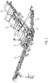
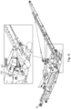
- Fig. 3a shows a perspective view of a screening assembly 102 according to a specific implementation of the present invention. It includes an assembly frame 201 which may be rigidly or detachably coupled to the machine mainframe 103, the assembly frame 201 carries a screening device 202 that may accommodate vertically-stacked multiple screens.
- the assembly frame 201 may have on either side one or more jacking legs 204 that may be extendable, for supporting the whole screening assembly on the ground when the screening assembly is detached from the mobile crusher.
- a transfer conveyor 205 is mounted on the assembly frame and arranged transverse to the longitudinal orientation of the assembly. It is located adjacent to the screen discharge end for receiving over-sized material passing over the discharge end of a screen, and may include an endless belt driven by a motor enabling the belt to run in both forward or backward directions.
- the transfer conveyor 205 forwards material onto a recirculation conveyor 207.
- the assembly frame 201 may be comprised of two sub-frames: a carrier frame 211 and a screen support frame 212, the carrier frame 211 carries a transfer conveyor 205 and includes couplings suitable for couplable with a mobile crusher.
- the screen support frame 212 is movably coupled to the carrier frame 211 at rearward end via a drive means 401; at a position towards its forward end i.e.
- the screen support frame 212 is pivotably attached to the carrier frame 211 via a connecting means 203 which may be an arm or a cylinder or a telescopic arm powered by a cylinder 302; the connecting means 203 is preferably a screen angle adjust support that may be set up for adjusting the tilting angle of the screening device 202, the screen angle adjust support may be a piston cylinder arrangement.
- the screening device 202 is mounted on the screen support frame 212 by a number of vibration reduction units such as springs or equivalent
- the screening device 202 may be defined by a pair of substantially parallel side walls which are interconnected by transversely extending bridging members. Two or more decks, i.e. upper deck 501 and lower deck 502, may be mounted on the bridging members. Each screen deck has small openings or slots or apertures for under-sized particles to pass through. The openings in the upper deck are larger than those of the lower deck.
- a vibration generation means 215 is incorporated for inparting vibration onto the screens to permit material to move under gravity on the screens or pass through the screens.
- the screening device may be of the doublescreen type, as shown in Fig. 3b , wherein the screening device has two upper decks cascaded along the longitudinal direction of the screening device such that the material may pass over an upper deck and sequentially onto the next stage upper deck, and a similar structure implemented for the lower decks.
- the screening device may include two inline independent screenboxes.
- a recirculation conveyor 207 is arranged on one side of the assembly frame, it is rotatable about an attachment bracket 209 to permit its receiving end to be positioned adjacent to the transfer conveyor so that the material from the transfer conveyor is delivered to the recirculation conveyor 207.
- a fines conveyor 206 is further secured to the assembly frame 201, in particular secured to the screen support frame 212, and arranged beneath the screening device 202 for receiving under-sized material passing through the screens and transporting the material to the forward end of the assembly.
- Fig.4 a magnified view of the coupling between the carrier frame and the rearward end of the screen support frame is shown.
- the screening assembly 102 is equipped with a cylinder 401, one end 405 of the cylinder is pivotably coupled to the carrier frame 211, the other end of the cylinder is pivotably connected to a pivot pin 402 of the screen support frame, the carrier frame 211 includes a slot 403 that is substantially upright and tilting slightly rearward, the cylinder 401 may lift the pin 402 upward or downward to displace the discharge end of the screening device, this movement is enabled due to the screen support frame 212 being pivotably coupled to the carrier frame 211 at the forward end at pivot support 210.
- a latching bracket 404 may be implemented to lock the pivot pin 402 within the slot firmly in position, especially when the screening device is brought to a higher slot position as shown in Fig. 4 .
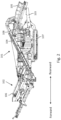
- Fig. 5 shows, the screen support frame 212 is placed at its lower slot position where over-sized material passing over the discharge end of the upper deck 501 is delivered to the transfer conveyor 205, parallelly over-sized material passing over the discharge end of the lower deck 502 is delivered to the stockpile conveyor 208 arranged substantially below the transfer conveyor.
- a chute can be arranged for guiding the material from the decks onto the conveyors, or for the purpose of preventing dust emission to the air environment.
- the belt on the transfer conveyor runs opposite to that of the belt on stockpile conveyor.
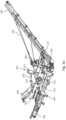
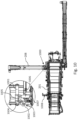
- the carrier frame 211 includes a pair of generally upstanding posts 703 having slots 403 embedded therein, and a pair of standing posts 705 leaning oppositely against and joining the posts 703 respectively at each side, as well as elongate beams 707 for connecting and binding the lower ends of the posts.
- the carrier frame 211 may further include at least one cross strut 704 and/or at least one cross bar 706 extending between the posts and the beams to reinforce the frame. These elements may be fixed together by bolts and the like, in practice some of these elements may be welded together.
- the carrier frame 211 may include a pair of upper coupling 701 and lower coupling 702 on either side to allow the screening assembly to be coupled to machine mainframe 103.
- This coupling 701, 702 may be in the form of hook which may complementarily engage a pin connection on the machine mainframe 103, alternatively it would be possible for this coupling to be a single boss/bush mounted by a single pin/bolt through the hole.
- a pivot bracket 1000 is also shown which can be mounted at the carrier frame for rotatably supporting the stockpile conveyor 208.
- An attachment bracket 209 is mounted on the carrier frame 211, and configured to rotatably support the recirculation conveyor 207, the bracket 209 includes a slewing arm 709 extending downwardly and be rotatable about a vertical axis, the slewing arm 709 at its distal end is pivotably coupled to a proximal end of the recirculation conveyor 207 at a pivot joint 213.
- the recirculation conveyor at its distal end and/or at mid-section is attached to the connectors 712 via connecting bars, strings, ropes, or rods and the like 214, so as to allow the recirculation conveyor 207 to be rotatably suspended on the carrier frame 211. Referring to Fig.3 , the recirculation conveyor is rotatable in the horizontal plane in a range of 180 degrees.
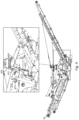
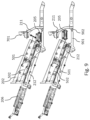
- Fig. 8 shows a perspective view of the carrier frame seen from the top.
- the elongate beam 707 at the rearward end extends laterally outward to form an angled support arm, in particular, the elongate beam is of sleeve structure where a beam 801 is slidably extendable within the sleeve, the beam 801 at its rearward end has coupling 702 on it, this configuration is advantageous for the screening assembly to match and adapt to different mobile crushers.
- the beam 801 can be retracted to a certain degree; otherwise the beam 801 can be extended to allow a large distance between couplings 702.
- the figure on righthand side shows the beam in extended state.
- an alternative solution is to have the transfer conveyor to be shifted by a drive means to allow the transfer conveyor to be positioned in two work positions. In the first work position as shown in the bottom of Fig. 9 , the transfer conveyor receives material from the upper deck, whereas in the second work position as shown on the top of Fig. 9 , the transfer conveyor receives material from both upper and lower decks.
- the screen support frame 212 is pivotably engaged with the carrier frame 211 at pivotable coupling 902, a connecting arm (not shown) in the from of a piston/cylinder device or a telescopic arm driven by a piston/cylinder and the like, connects the screen support frame 212 at its forward end (in particular, at a position departing from the rearward end of the screen support frame) to the coupling 701 of carrier frame 211.
- the transfer conveyor 205 may be movably supported by the carrier frame 211, a drive means (not shown) may lift or lower the transfer conveyor 205 in substantially vertical direction, however parallelly the transfer conveyor 205 may need also to move slightly forward or backward.
- the arrow in the top figure indicates the moving direction of the transfer conveyor 205.
- a chute or guiding plate may be introduced to guide the material from the deck onto the transfer conveyor.
- the transfer conveyor 205 has been raised to a upper position, thus leaving clearance between the transfer conveyor and the elongate beam 901 of the assembly frame.
- a receiving end of the stockpile conveyor 208 may be in the form of a cantilever structure, which is suitable for being inserted or embedded within the clearance/space, so as to allow the stockpile conveyor 208 to receive material from the lower deck 502.
- Fig. 10 depicts a stockpile conveyor pivot bracket 1000.
- the stockpile conveyor 208 is rotatable in the range of 0° to 90° from its work position as shown in Fig. 10 to a non-work position as shown in Fig. 11 .
- the pivot bracket 1000 has a carrier 1001 to pivotably hold the conveyor 208 on both sides.
- a carrier support 1003 extends laterally from the assembly frame 201 and includes a vertical pivot 1002, the carrier support 1003 carries an arm 1004 that is slewable about vertical pivot 1002, the distal end of the arm 1004 connects to a seat 1005 for holding the carrier 1001.
- the carrier 1001, the arm 1004 & the seat 1005 may be all part of one welded structure.
- a cylinder 1006 has one end pivotably coupled to the carrier frame 211, the distal end of the cylinder is rotatably connected to the seat 1005.
- the powered cylinder 1006 may drive the stockpile conveyor 208 to rotate about the vertical pivot 1002.
- the stockpile conveyor 208 In its work position the stockpile conveyor 208 may be further supported from above at a position torwards its distal end by use of wire ropes 301 that can be extended/restracted to change the angle of the conveyor for operation/transport.
- the conveyor 208 is placed parallel to the longitudinal direction of the assembly and rests on the assembly frame via a foldable support 1008.
- the screening assembly is adjusted by the aid of cylinder 401 to set the assembly in an intended work position, i.e. the screen support frame 212 is placed in a lower slot position as shown in Fig. 5 or raised into a higher slot position as shown in Fig. 6 .
- a vibration generating means is also started to impart vibration onto the screens.
- the material to be processed is brought by a loading truck or a conveyor and fed to the chute 105, the material is subsequently conveyed by the belt conveyor 108 to the crusher 104, after having been processed by the crusher the material is then loaded on the rearward end of the supply conveyor 106, which in turn transports the material towards the forward end to the screening device 202.
- material flow path may vary. If the screen support frame 212 is raised into a higher slot position as shown in Fig. 6 , material moves under gravity along the surface of vibrating decks and passes over the discharge end of both decks, and falls onto the transfer conveyor 205, and subsequently be transported onto the belt of recirculation conveyor 207, the recirculation conveyor 207 brings the over-sized material back to chute 105 for recycling processing.
- the screen support frame 212 is placed in a lower slot position as shown in Fig. 5 , it is necessary to set up the stockpile conveyor 208, i.e. to bring it to a transverse position as shown in Fig. 10 , the receiving end of stockpile conveyor 208 is located adjacent the lower deck, so that material passing over the lower deck 502 falls on the stockpile conveyor 208 and is transported laterally to the distal end, for stock piling or onward processing. Material from the upper deck 501 falls on the transfer conveyor 205 and be returned by recirculation conveyor 207 back to the chute 105 for recycling.
- Material passing through the lower deck drops on the fines conveyor 206 and is conveyed to the forward end of the assembly.
- the screening assembly and the mobile material processing plant can be used in the mining or recycling or construction industry etc. for bulk material processing such as crushing, sizing, stockpiling and the like.
Landscapes
- Disintegrating Or Milling (AREA)
- Combined Means For Separation Of Solids (AREA)
- Sorting Of Articles (AREA)
- Intermediate Stations On Conveyors (AREA)
Claims (16)
- Siebanordnung zum Sieben von Material und umfassend:- einen Anordnungsrahmen (201);- eine Siebvorrichtung (202), die an den Anordnungsrahmen gekoppelt ist, die ein erstes Sieb (501) und ein zweites Sieb (502) beinhaltet, wobei das zweite Sieb im Wesentlichen vertikal unter dem ersten Sieb gestapelt ist;- ein erstes Förderband (205), das an den Anordnungsrahmen gekoppelt ist und dazu konfiguriert ist, an einem Aufnahmeende Material von mindestens einem der Siebe an ihren jeweiligen Abgabeenden aufzunehmen; und- ein Antriebsmittel (401), das an dem Anordnungsrahmen montiert ist;dadurch gekennzeichnet, dass das Antriebsmittel dazu betreibbar ist, mindestens eines von dem Abgabeende der Siebvorrichtung und dem Aufnahmeende des ersten Förderbands relativ zu dem Anordnungsrahmen (201) zu verschieben, um es dem ersten Förderband (205) zu ermöglichen, selektiv Material von dem ersten Sieb (501) an dessen Abgabeende oder von dem ersten und dem zweiten Sieb (501, 502) an deren jeweiligen Abgabeenden aufzunehmen, und wobei das erste Förderband (205) ein Übertragungsförderband ist, das quer relativ zu der Längsrichtung der Siebvorrichtung (202) angeordnet ist.
- Anordnung nach Anspruch 1, wobei der Anordnungsrahmen (201) einen Tragrahmen (211) und einen Siebstützrahmen (212), der bewegbar an den Tragrahmen (211) gekoppelt ist, beinhaltet, wobei der Tragrahmen (211) dazu konfiguriert ist, das erste Förderband (205) zu stützen, und der Siebstützrahmen (212) dazu konfiguriert ist, die Siebvorrichtung (202) zu stützen.
- Anordnung nach einem der vorhergehenden Ansprüche, wobei die Siebanordnung ferner ein zweites Förderband (206) beinhaltet, das an den Anordnungsrahmen gekoppelt und unter der Siebvorrichtung (202) angeordnet ist, um unterdimensioniertes Material von der Siebvorrichtung (202) aufzunehmen.
- Anordnung nach einem der vorhergehenden Ansprüche, wobei der Verschiebevorgang Anheben oder Absenken von mindestens einem des Abgabeendes der Siebvorrichtung (202) und des Aufnahmeendes des ersten Förderbands relativ zu dem Anordnungsrahmen beinhaltet.
- Anordnung nach Anspruch 2, wobei das Antriebsmittel eine Kolben-/Zylindervorrichtung (401) ist, die bevorzugt hydraulisch betätigt wird, deren erstes Ende (402) schwenkbar an einem von dem Siebstützrahmen (212) und dem ersten Förderband (205) befestigt ist, wobei das zweite Ende (405) der Kolben-/Zylindervorrichtung (401) schwenkbar mit dem Tragrahmen (211) verbunden ist, wobei das Antriebsmittel optional über einen Teleskopausleger auf eines von der Siebvorrichtung und dem ersten Förderband einwirkt.
- Anordnung nach Anspruch 5, wobei der Tragrahmen einen Schlitz (403) und eine Verriegelungshalterung (404) beinhaltet, wobei eines von dem Siebstützrahmen und dem ersten Förderband eine Kopplung beinhaltet, bevorzugt eine Stiftstütze (402), die dazu konfiguriert ist, in das erste Ende des Antriebsmittels (401) oder des Teleskopauslegers einzugreifen, wobei die Verriegelungshalterung (404) dazu betreibbar ist, die Kopplung (402) innerhalb des Schlitzes (403) zu verriegeln.
- Anordnung nach einem der Ansprüche 2 und 5-6, die ferner ein zweites Antriebsmittel (203) beinhaltet, bevorzugt eine Kolben-/Zylindervorrichtung oder einen Teleskopausleger (203), der durch eine Kolben-/Zylindervorrichtung (302) angetrieben wird und mit dem Tragrahmen (211) und dem Siebstützrahmen (212) kommuniziert und dazu betreibbar ist, den Neigungswinkel der Siebvorrichtung (202) zu ändern.
- Anordnung nach Anspruch 3, wobei die Siebanordnung ferner ein drittes Förderband (208) beinhaltet, das an den Anordnungsrahmen gekoppelt ist, quer relativ zu der Längsrichtung der Siebvorrichtung (202) angeordnet und dazu betreibbar ist, überdimensioniertes Material von dem Abgabeende des zweiten Siebs aufzunehmen, wobei das dritte Förderband insbesondere bevorzugt ein Haldenförderband ist.
- Anordnung nach einem der vorhergehenden Ansprüche, wobei die Anordnung ferner ein Rückführförderband (207) beinhaltet, das an dem Anordnungsrahmen (201) montiert ist, um Material aufzunehmen, das von dem ersten Förderband (205) bereitgestellt wird.
- Anordnung nach Anspruch 8, wobei das dritte Förderband (208) in einer horizontalen Ebene um einen Schwenkmechanismus des Anordnungsrahmens drehbar ist.
- Anordnung nach einem der vorhergehenden Ansprüche, wobei das erste Förderband (205) und/oder das Antriebsmittel (401) und/oder das Rückführförderband (207) getrennt von dem Anordnungsrahmen (201) montiert sind, insbesondere das erste Förderband (205) und/oder das Antriebsmittel und/oder das Rückführförderband (207) an einer Basismaschine (101) montiert sind, wobei die Basismaschine bevorzugt ein mobiler Zerkleinerer ist.
- Anordnung nach Anspruch 11, wobei der Anordnungsrahmen (201) dazu konfiguriert ist, derart abnehmbar an die Basismaschine (101) gekoppelt zu sein, dass beim Koppeln ein Zufuhrförderband (106) der Basismaschine dazu konfiguriert ist, über dem ersten Sieb (501) angeordnet zu sein und dem ersten Sieb Material zuzuführen.
- Anordnung nach Anspruch 11 oder 12, wobei der Anordnungsrahmen Stützarme (707) beinhaltet, die dazu konfiguriert sind, mit der Basismaschine (101) koppelbar zu sein, wobei die Arme (707) einen abgewinkelten teleskopischen Abschnitt (801) aufweisen.
- Anordnung nach einem der vorhergehenden Ansprüche, wobei die Siebvorrichtung (202) und/oder die Förderbänder (205, 206, 207, 208) und/oder der Anordnungsrahmen (201) und/oder die Befestigungshalterung (209), die an dem Stützrahmen (211) montiert ist und dazu konfiguriert ist, das Rückführförderband (207) drehbar zu stützen, jeweils von modularer Struktur sind, wobei bevorzugt jedes mit verschiedenen Modulen konstruiert ist, die miteinander verschraubt sind.
- Verfahren zum Verarbeiten von Material in einer Siebanordnung nach einem der Ansprüche 1 bis 14, wobei das Verfahren Einstellen der Siebanordnung mithilfe des Antriebsmittels (401) umfasst, um die Anordnung in eine vorgesehene Arbeitsposition zu bringen, wobei mindestens eines von dem Abgabeende der Siebvorrichtung und dem Aufnahmeende des ersten Förderbands durch das Antriebsmittel relativ zu dem Anordnungsrahmen verschiebbar ist, um es dem ersten Förderband (205) zu ermöglichen, selektiv Material von dem ersten Sieb (501) an dessen Abgabeende oder von dem ersten und dem zweiten Sieb (501, 502) an deren jeweiligen Abgabeenden aufzunehmen;- Erzeugen von Vibration auf den Sieben, um es dem Material zu ermöglichen, sich mittels Schwerkraft auf den Sieben zu bewegen oder die Siebe zu passieren;- Zuführen von zu siebendem Material auf die Oberfläche des ersten Siebs (501); und- Befördern von Material, das durch das erste Förderband (205) von dem Abgabeende der Siebvorrichtung bereitgestellt wird.
- Mobile Materialverarbeitungsanlage, beinhaltend die Anordnung nach einem der Ansprüche 1 bis 14.
Priority Applications (12)
| Application Number | Priority Date | Filing Date | Title |
|---|---|---|---|
| FIEP17201324.5T FI3482836T4 (fi) | 2017-11-13 | 2017-11-13 | Seulakokoonpano ja siirrettävä materiaalinkäsittelykone |
| EP17201324.5A EP3482836B2 (de) | 2017-11-13 | 2017-11-13 | Screeninganordnung und mobile materialbearbeitungsmaschine |
| PL17201324.5T PL3482836T5 (pl) | 2017-11-13 | 2017-11-13 | Zespół przesiewający i mobilna maszyna do przetwarzania materiałów |
| PCT/EP2018/080937 WO2019092243A1 (en) | 2017-11-13 | 2018-11-12 | Screening assembly and mobile material processing machine |
| US16/763,397 US11511319B2 (en) | 2017-11-13 | 2018-11-12 | Screening assembly and mobile material processing machine |
| AU2018363808A AU2018363808B2 (en) | 2017-11-13 | 2018-11-12 | Screening assembly and mobile material processing machine |
| BR112020009272-0A BR112020009272B1 (pt) | 2017-11-13 | 2018-11-12 | Montagem de peneiramento para peneiramento de material, método para processar material em uma montagem de peneiramento e planta de processamento de material móvel |
| CN201880072864.0A CN111344071B (zh) | 2017-11-13 | 2018-11-12 | 筛分组件和移动式物料处理机 |
| RU2020117751A RU2020117751A (ru) | 2017-11-13 | 2018-11-12 | Узел грохочения и передвижная машина для обработки материала |
| CA3080921A CA3080921C (en) | 2017-11-13 | 2018-11-12 | Screening assembly and mobile material processing machine |
| ZA2020/02273A ZA202002273B (en) | 2017-11-13 | 2020-05-04 | Screening assembly and mobile material processing machine |
| CL2020001216A CL2020001216A1 (es) | 2017-11-13 | 2020-05-07 | Ensamblaje de cribado y máquina para el procesamiento de material móvil |
Applications Claiming Priority (1)
| Application Number | Priority Date | Filing Date | Title |
|---|---|---|---|
| EP17201324.5A EP3482836B2 (de) | 2017-11-13 | 2017-11-13 | Screeninganordnung und mobile materialbearbeitungsmaschine |
Publications (3)
| Publication Number | Publication Date |
|---|---|
| EP3482836A1 EP3482836A1 (de) | 2019-05-15 |
| EP3482836B1 EP3482836B1 (de) | 2020-06-17 |
| EP3482836B2 true EP3482836B2 (de) | 2024-12-11 |
Family
ID=60301987
Family Applications (1)
| Application Number | Title | Priority Date | Filing Date |
|---|---|---|---|
| EP17201324.5A Active EP3482836B2 (de) | 2017-11-13 | 2017-11-13 | Screeninganordnung und mobile materialbearbeitungsmaschine |
Country Status (10)
| Country | Link |
|---|---|
| US (1) | US11511319B2 (de) |
| EP (1) | EP3482836B2 (de) |
| CN (1) | CN111344071B (de) |
| AU (1) | AU2018363808B2 (de) |
| CL (1) | CL2020001216A1 (de) |
| FI (1) | FI3482836T4 (de) |
| PL (1) | PL3482836T5 (de) |
| RU (1) | RU2020117751A (de) |
| WO (1) | WO2019092243A1 (de) |
| ZA (1) | ZA202002273B (de) |
Families Citing this family (15)
| Publication number | Priority date | Publication date | Assignee | Title |
|---|---|---|---|---|
| US10537918B2 (en) * | 2017-11-21 | 2020-01-21 | Kringstad Ironworks, Inc. | Piler conveyor system |
| DE102019120580B4 (de) * | 2019-07-30 | 2021-04-01 | Kleemann Gmbh | Gesteins-Bearbeitungsmaschine |
| DE102019126778A1 (de) | 2019-10-04 | 2021-04-08 | Kleemann Gmbh | Gesteinsverarbeitungsanlage |
| FI129449B (en) | 2019-12-18 | 2022-02-28 | Metso Minerals Inc | Mobile multi-deck screening apparatus pile control |
| FI129228B2 (en) * | 2020-09-22 | 2023-12-20 | Metso Outotec Finland Oy | Sight attachment system |
| DE102020126743A1 (de) * | 2020-10-12 | 2022-04-14 | Kleemann Gmbh | Materialverarbeitungseinrichtung |
| DE102020130981A1 (de) | 2020-11-24 | 2022-05-25 | Kleemann Gmbh | Aufbereitungsanlage |
| US11865582B2 (en) | 2021-03-15 | 2024-01-09 | Portafill International Limited | Combination screening apparatus |
| EP4059622B1 (de) * | 2021-03-15 | 2023-07-19 | Portafill International Limited | Siebvorrichtung mit mehrfachausgabe |
| US20220288640A1 (en) * | 2021-03-15 | 2022-09-15 | Portafill International Limited | Screen apparatus with multi-discharge |
| EP4094850B1 (de) * | 2021-05-27 | 2024-03-20 | Sandvik Ltd | Siebvorrichtung mit geteiltem deck zum sieben von schüttgut |
| FI130635B (en) * | 2021-12-27 | 2023-12-21 | Metso Finland Oy | Pivoting processing device of mobile mineral material processing plant |
| FI20225017A1 (en) * | 2022-01-11 | 2023-07-12 | Metso Outotec Finland Oy | Transfer system for the output of mineral material screening |
| DE102022112640B3 (de) * | 2022-05-19 | 2023-03-16 | Kleemann Gmbh | Aufbereitungsanlage |
| EP4353369A1 (de) * | 2022-10-11 | 2024-04-17 | McGrath Engineering Limited | Mobiles sieb- und aufschüttsgerät |
Family Cites Families (18)
| Publication number | Priority date | Publication date | Assignee | Title |
|---|---|---|---|---|
| US4383651A (en) * | 1980-10-20 | 1983-05-17 | Allis-Chalmers Corporation | Portable crushing and screening plant |
| IE970078A1 (en) * | 1996-02-07 | 2000-08-23 | Erin Intellectual Property Ltd | A mobile screen |
| US6186338B1 (en) * | 1996-05-03 | 2001-02-13 | Patrick Joseph Douglas | Self-propelled material-processing apparatus |
| BE1010451A6 (nl) | 1996-08-02 | 1998-08-04 | Brecon Nv | Zeefmachine. |
| US6698594B2 (en) * | 2002-03-18 | 2004-03-02 | Ohio Central Steel Company | Screening machine |
| GB0202706D0 (en) * | 2002-02-06 | 2002-03-20 | Bl Pegson Ltd | Screen assembly |
| DE10221253A1 (de) | 2002-05-13 | 2003-11-27 | Backers Maschb Gmbh | Vorrichtung zum Sieben, Sortieren oder Zerkleinern von schüttfähigen Gütern |
| US6935587B2 (en) * | 2002-06-06 | 2005-08-30 | Johnson Crushers International | Mobile rock crushing plant |
| FI20021428A7 (fi) | 2002-07-31 | 2004-02-01 | Metso Minerals Tampere Oy | Menetelmä seulontakoneen ohjaamiseksi ja seulontakone |
| CN101384378A (zh) | 2006-02-16 | 2009-03-11 | 奥贾伊研究与设计有限公司 | 材料筛选设备 |
| US8162245B2 (en) * | 2006-06-22 | 2012-04-24 | Terex Usa, Llc | Mobile aggregate crushing system and method |
| US8820536B2 (en) * | 2011-08-10 | 2014-09-02 | Terex Usa, Llc | Platform and ladder interface for variable slope vibrating screens |
| FI127094B (fi) | 2012-01-03 | 2017-11-15 | Metso Minerals Inc | Materiaalin prosessointilaitos |
| CN105592928B (zh) * | 2013-09-04 | 2018-06-12 | 美卓矿物公司 | 矿物材料加工设备以及用于操作加工设备的方法 |
| CN105517712B (zh) * | 2013-09-04 | 2018-10-09 | 美卓矿物公司 | 矿物材料加工设施以及操作加工设施的方法 |
| AU2014407942A1 (en) * | 2014-10-03 | 2017-03-30 | Sandvik Intellectual Property Ab | Mobile bulk material processing machine with demountable hanging assembly |
| GB2523658B (en) * | 2015-02-06 | 2019-10-30 | Cde Global Ltd | A multi-deck screening assembly |
| DE102019126778A1 (de) * | 2019-10-04 | 2021-04-08 | Kleemann Gmbh | Gesteinsverarbeitungsanlage |
-
2017
- 2017-11-13 FI FIEP17201324.5T patent/FI3482836T4/fi active
- 2017-11-13 EP EP17201324.5A patent/EP3482836B2/de active Active
- 2017-11-13 PL PL17201324.5T patent/PL3482836T5/pl unknown
-
2018
- 2018-11-12 US US16/763,397 patent/US11511319B2/en active Active
- 2018-11-12 WO PCT/EP2018/080937 patent/WO2019092243A1/en not_active Ceased
- 2018-11-12 RU RU2020117751A patent/RU2020117751A/ru unknown
- 2018-11-12 CN CN201880072864.0A patent/CN111344071B/zh active Active
- 2018-11-12 AU AU2018363808A patent/AU2018363808B2/en active Active
-
2020
- 2020-05-04 ZA ZA2020/02273A patent/ZA202002273B/en unknown
- 2020-05-07 CL CL2020001216A patent/CL2020001216A1/es unknown
Also Published As
| Publication number | Publication date |
|---|---|
| US20210069750A1 (en) | 2021-03-11 |
| BR112020009272A2 (pt) | 2020-10-27 |
| WO2019092243A1 (en) | 2019-05-16 |
| EP3482836A1 (de) | 2019-05-15 |
| PL3482836T3 (pl) | 2020-11-16 |
| ZA202002273B (en) | 2022-09-28 |
| RU2020117751A3 (de) | 2021-12-15 |
| CN111344071A (zh) | 2020-06-26 |
| AU2018363808B2 (en) | 2024-05-30 |
| CA3080921A1 (en) | 2019-05-16 |
| CN111344071B (zh) | 2022-09-20 |
| FI3482836T4 (fi) | 2025-03-17 |
| PL3482836T5 (pl) | 2025-04-28 |
| EP3482836B1 (de) | 2020-06-17 |
| CL2020001216A1 (es) | 2020-12-18 |
| AU2018363808A1 (en) | 2020-05-07 |
| US11511319B2 (en) | 2022-11-29 |
| RU2020117751A (ru) | 2021-12-15 |
Similar Documents
| Publication | Publication Date | Title |
|---|---|---|
| US11511319B2 (en) | Screening assembly and mobile material processing machine | |
| EP0641607B1 (de) | Mobile Anlage für die Behandlung von Aggregatmaterial | |
| US10668503B2 (en) | Transfer conveyor assembly for a screening apparatus | |
| US6935587B2 (en) | Mobile rock crushing plant | |
| US7273150B2 (en) | Portable screening machine | |
| CN112604939B (zh) | 岩石加工设备 | |
| JP5822954B2 (ja) | 鉱物材料処理用の可動式処理装置 | |
| US6065606A (en) | Elevatable frame for transportable sorting machines | |
| CA3080921C (en) | Screening assembly and mobile material processing machine | |
| US12103041B2 (en) | Portable screening and stockpiling apparatus | |
| BR112020009272B1 (pt) | Montagem de peneiramento para peneiramento de material, método para processar material em uma montagem de peneiramento e planta de processamento de material móvel | |
| AU714167B2 (en) | A transportable rock screening plant | |
| CN117085828A (zh) | 加工设备 | |
| GB2302514A (en) | A transportable rock screening plant |
Legal Events
| Date | Code | Title | Description |
|---|---|---|---|
| PUAI | Public reference made under article 153(3) epc to a published international application that has entered the european phase |
Free format text: ORIGINAL CODE: 0009012 |
|
| STAA | Information on the status of an ep patent application or granted ep patent |
Free format text: STATUS: THE APPLICATION HAS BEEN PUBLISHED |
|
| AK | Designated contracting states |
Kind code of ref document: A1 Designated state(s): AL AT BE BG CH CY CZ DE DK EE ES FI FR GB GR HR HU IE IS IT LI LT LU LV MC MK MT NL NO PL PT RO RS SE SI SK SM TR |
|
| AX | Request for extension of the european patent |
Extension state: BA ME |
|
| STAA | Information on the status of an ep patent application or granted ep patent |
Free format text: STATUS: REQUEST FOR EXAMINATION WAS MADE |
|
| 17P | Request for examination filed |
Effective date: 20191115 |
|
| RBV | Designated contracting states (corrected) |
Designated state(s): AL AT BE BG CH CY CZ DE DK EE ES FI FR GB GR HR HU IE IS IT LI LT LU LV MC MK MT NL NO PL PT RO RS SE SI SK SM TR |
|
| GRAP | Despatch of communication of intention to grant a patent |
Free format text: ORIGINAL CODE: EPIDOSNIGR1 |
|
| STAA | Information on the status of an ep patent application or granted ep patent |
Free format text: STATUS: GRANT OF PATENT IS INTENDED |
|
| INTG | Intention to grant announced |
Effective date: 20200116 |
|
| GRAS | Grant fee paid |
Free format text: ORIGINAL CODE: EPIDOSNIGR3 |
|
| GRAA | (expected) grant |
Free format text: ORIGINAL CODE: 0009210 |
|
| STAA | Information on the status of an ep patent application or granted ep patent |
Free format text: STATUS: THE PATENT HAS BEEN GRANTED |
|
| AK | Designated contracting states |
Kind code of ref document: B1 Designated state(s): AL AT BE BG CH CY CZ DE DK EE ES FI FR GB GR HR HU IE IS IT LI LT LU LV MC MK MT NL NO PL PT RO RS SE SI SK SM TR |
|
| REG | Reference to a national code |
Ref country code: GB Ref legal event code: FG4D |
|
| REG | Reference to a national code |
Ref country code: CH Ref legal event code: EP |
|
| REG | Reference to a national code |
Ref country code: DE Ref legal event code: R096 Ref document number: 602017018236 Country of ref document: DE |
|
| REG | Reference to a national code |
Ref country code: IE Ref legal event code: FG4D |
|
| REG | Reference to a national code |
Ref country code: AT Ref legal event code: REF Ref document number: 1280687 Country of ref document: AT Kind code of ref document: T Effective date: 20200715 |
|
| REG | Reference to a national code |
Ref country code: FI Ref legal event code: FGE |
|
| REG | Reference to a national code |
Ref country code: SE Ref legal event code: TRGR |
|
| REG | Reference to a national code |
Ref country code: NO Ref legal event code: T2 Effective date: 20200617 |
|
| PG25 | Lapsed in a contracting state [announced via postgrant information from national office to epo] |
Ref country code: LT Free format text: LAPSE BECAUSE OF FAILURE TO SUBMIT A TRANSLATION OF THE DESCRIPTION OR TO PAY THE FEE WITHIN THE PRESCRIBED TIME-LIMIT Effective date: 20200617 Ref country code: GR Free format text: LAPSE BECAUSE OF FAILURE TO SUBMIT A TRANSLATION OF THE DESCRIPTION OR TO PAY THE FEE WITHIN THE PRESCRIBED TIME-LIMIT Effective date: 20200918 |
|
| REG | Reference to a national code |
Ref country code: LT Ref legal event code: MG4D |
|
| REG | Reference to a national code |
Ref country code: NL Ref legal event code: MP Effective date: 20200617 |
|
| PG25 | Lapsed in a contracting state [announced via postgrant information from national office to epo] |
Ref country code: BG Free format text: LAPSE BECAUSE OF FAILURE TO SUBMIT A TRANSLATION OF THE DESCRIPTION OR TO PAY THE FEE WITHIN THE PRESCRIBED TIME-LIMIT Effective date: 20200917 Ref country code: RS Free format text: LAPSE BECAUSE OF FAILURE TO SUBMIT A TRANSLATION OF THE DESCRIPTION OR TO PAY THE FEE WITHIN THE PRESCRIBED TIME-LIMIT Effective date: 20200617 Ref country code: LV Free format text: LAPSE BECAUSE OF FAILURE TO SUBMIT A TRANSLATION OF THE DESCRIPTION OR TO PAY THE FEE WITHIN THE PRESCRIBED TIME-LIMIT Effective date: 20200617 Ref country code: HR Free format text: LAPSE BECAUSE OF FAILURE TO SUBMIT A TRANSLATION OF THE DESCRIPTION OR TO PAY THE FEE WITHIN THE PRESCRIBED TIME-LIMIT Effective date: 20200617 |
|
| PG25 | Lapsed in a contracting state [announced via postgrant information from national office to epo] |
Ref country code: AL Free format text: LAPSE BECAUSE OF FAILURE TO SUBMIT A TRANSLATION OF THE DESCRIPTION OR TO PAY THE FEE WITHIN THE PRESCRIBED TIME-LIMIT Effective date: 20200617 Ref country code: NL Free format text: LAPSE BECAUSE OF FAILURE TO SUBMIT A TRANSLATION OF THE DESCRIPTION OR TO PAY THE FEE WITHIN THE PRESCRIBED TIME-LIMIT Effective date: 20200617 |
|
| PG25 | Lapsed in a contracting state [announced via postgrant information from national office to epo] |
Ref country code: ES Free format text: LAPSE BECAUSE OF FAILURE TO SUBMIT A TRANSLATION OF THE DESCRIPTION OR TO PAY THE FEE WITHIN THE PRESCRIBED TIME-LIMIT Effective date: 20200617 Ref country code: SM Free format text: LAPSE BECAUSE OF FAILURE TO SUBMIT A TRANSLATION OF THE DESCRIPTION OR TO PAY THE FEE WITHIN THE PRESCRIBED TIME-LIMIT Effective date: 20200617 Ref country code: EE Free format text: LAPSE BECAUSE OF FAILURE TO SUBMIT A TRANSLATION OF THE DESCRIPTION OR TO PAY THE FEE WITHIN THE PRESCRIBED TIME-LIMIT Effective date: 20200617 Ref country code: RO Free format text: LAPSE BECAUSE OF FAILURE TO SUBMIT A TRANSLATION OF THE DESCRIPTION OR TO PAY THE FEE WITHIN THE PRESCRIBED TIME-LIMIT Effective date: 20200617 Ref country code: PT Free format text: LAPSE BECAUSE OF FAILURE TO SUBMIT A TRANSLATION OF THE DESCRIPTION OR TO PAY THE FEE WITHIN THE PRESCRIBED TIME-LIMIT Effective date: 20201019 |
|
| PG25 | Lapsed in a contracting state [announced via postgrant information from national office to epo] |
Ref country code: SK Free format text: LAPSE BECAUSE OF FAILURE TO SUBMIT A TRANSLATION OF THE DESCRIPTION OR TO PAY THE FEE WITHIN THE PRESCRIBED TIME-LIMIT Effective date: 20200617 Ref country code: IS Free format text: LAPSE BECAUSE OF FAILURE TO SUBMIT A TRANSLATION OF THE DESCRIPTION OR TO PAY THE FEE WITHIN THE PRESCRIBED TIME-LIMIT Effective date: 20201017 |
|
| REG | Reference to a national code |
Ref country code: DE Ref legal event code: R026 Ref document number: 602017018236 Country of ref document: DE |
|
| PLBI | Opposition filed |
Free format text: ORIGINAL CODE: 0009260 |
|
| PLAX | Notice of opposition and request to file observation + time limit sent |
Free format text: ORIGINAL CODE: EPIDOSNOBS2 |
|
| REG | Reference to a national code |
Ref country code: FI Ref legal event code: MDE Opponent name: KLEEMANN GMBH |
|
| 26 | Opposition filed |
Opponent name: KLEEMANN GMBH Effective date: 20210312 |
|
| PG25 | Lapsed in a contracting state [announced via postgrant information from national office to epo] |
Ref country code: DK Free format text: LAPSE BECAUSE OF FAILURE TO SUBMIT A TRANSLATION OF THE DESCRIPTION OR TO PAY THE FEE WITHIN THE PRESCRIBED TIME-LIMIT Effective date: 20200617 |
|
| PG25 | Lapsed in a contracting state [announced via postgrant information from national office to epo] |
Ref country code: SI Free format text: LAPSE BECAUSE OF FAILURE TO SUBMIT A TRANSLATION OF THE DESCRIPTION OR TO PAY THE FEE WITHIN THE PRESCRIBED TIME-LIMIT Effective date: 20200617 |
|
| PG25 | Lapsed in a contracting state [announced via postgrant information from national office to epo] |
Ref country code: MC Free format text: LAPSE BECAUSE OF FAILURE TO SUBMIT A TRANSLATION OF THE DESCRIPTION OR TO PAY THE FEE WITHIN THE PRESCRIBED TIME-LIMIT Effective date: 20200617 |
|
| REG | Reference to a national code |
Ref country code: CH Ref legal event code: PL |
|
| PG25 | Lapsed in a contracting state [announced via postgrant information from national office to epo] |
Ref country code: LU Free format text: LAPSE BECAUSE OF NON-PAYMENT OF DUE FEES Effective date: 20201113 |
|
| PLBB | Reply of patent proprietor to notice(s) of opposition received |
Free format text: ORIGINAL CODE: EPIDOSNOBS3 |
|
| REG | Reference to a national code |
Ref country code: BE Ref legal event code: MM Effective date: 20201130 |
|
| PG25 | Lapsed in a contracting state [announced via postgrant information from national office to epo] |
Ref country code: CH Free format text: LAPSE BECAUSE OF NON-PAYMENT OF DUE FEES Effective date: 20201130 Ref country code: LI Free format text: LAPSE BECAUSE OF NON-PAYMENT OF DUE FEES Effective date: 20201130 |
|
| PG25 | Lapsed in a contracting state [announced via postgrant information from national office to epo] |
Ref country code: MT Free format text: LAPSE BECAUSE OF FAILURE TO SUBMIT A TRANSLATION OF THE DESCRIPTION OR TO PAY THE FEE WITHIN THE PRESCRIBED TIME-LIMIT Effective date: 20200617 Ref country code: CY Free format text: LAPSE BECAUSE OF FAILURE TO SUBMIT A TRANSLATION OF THE DESCRIPTION OR TO PAY THE FEE WITHIN THE PRESCRIBED TIME-LIMIT Effective date: 20200617 |
|
| PG25 | Lapsed in a contracting state [announced via postgrant information from national office to epo] |
Ref country code: MK Free format text: LAPSE BECAUSE OF FAILURE TO SUBMIT A TRANSLATION OF THE DESCRIPTION OR TO PAY THE FEE WITHIN THE PRESCRIBED TIME-LIMIT Effective date: 20200617 |
|
| REG | Reference to a national code |
Ref country code: AT Ref legal event code: UEP Ref document number: 1280687 Country of ref document: AT Kind code of ref document: T Effective date: 20200617 |
|
| PG25 | Lapsed in a contracting state [announced via postgrant information from national office to epo] |
Ref country code: BE Free format text: LAPSE BECAUSE OF NON-PAYMENT OF DUE FEES Effective date: 20201130 |
|
| P01 | Opt-out of the competence of the unified patent court (upc) registered |
Effective date: 20230603 |
|
| PUAH | Patent maintained in amended form |
Free format text: ORIGINAL CODE: 0009272 |
|
| STAA | Information on the status of an ep patent application or granted ep patent |
Free format text: STATUS: PATENT MAINTAINED AS AMENDED |
|
| 27A | Patent maintained in amended form |
Effective date: 20241211 |
|
| AK | Designated contracting states |
Kind code of ref document: B2 Designated state(s): AL AT BE BG CH CY CZ DE DK EE ES FI FR GB GR HR HU IE IS IT LI LT LU LV MC MK MT NL NO PL PT RO RS SE SI SK SM TR |
|
| REG | Reference to a national code |
Ref country code: DE Ref legal event code: R102 Ref document number: 602017018236 Country of ref document: DE |
|
| REG | Reference to a national code |
Ref country code: SE Ref legal event code: RPEO |
|
| PGFP | Annual fee paid to national office [announced via postgrant information from national office to epo] |
Ref country code: DE Payment date: 20250930 Year of fee payment: 9 |
|
| PGFP | Annual fee paid to national office [announced via postgrant information from national office to epo] |
Ref country code: GB Payment date: 20251001 Year of fee payment: 9 |
|
| PGFP | Annual fee paid to national office [announced via postgrant information from national office to epo] |
Ref country code: NO Payment date: 20251113 Year of fee payment: 9 |
|
| PGFP | Annual fee paid to national office [announced via postgrant information from national office to epo] |
Ref country code: AT Payment date: 20251027 Year of fee payment: 9 |
|
| PGFP | Annual fee paid to national office [announced via postgrant information from national office to epo] |
Ref country code: FI Payment date: 20251113 Year of fee payment: 9 Ref country code: IT Payment date: 20251022 Year of fee payment: 9 |
|
| PGFP | Annual fee paid to national office [announced via postgrant information from national office to epo] |
Ref country code: FR Payment date: 20251023 Year of fee payment: 9 |
|
| PGFP | Annual fee paid to national office [announced via postgrant information from national office to epo] |
Ref country code: TR Payment date: 20251105 Year of fee payment: 9 |
|
| PGFP | Annual fee paid to national office [announced via postgrant information from national office to epo] |
Ref country code: SE Payment date: 20251001 Year of fee payment: 9 |
|
| PGFP | Annual fee paid to national office [announced via postgrant information from national office to epo] |
Ref country code: IE Payment date: 20251001 Year of fee payment: 9 Ref country code: CZ Payment date: 20251103 Year of fee payment: 9 |
|
| PGFP | Annual fee paid to national office [announced via postgrant information from national office to epo] |
Ref country code: PL Payment date: 20251014 Year of fee payment: 9 |