EP3482462B1 - Flüssigkeitsgekühltes kontaktelement - Google Patents
Flüssigkeitsgekühltes kontaktelement Download PDFInfo
- Publication number
- EP3482462B1 EP3482462B1 EP17745974.0A EP17745974A EP3482462B1 EP 3482462 B1 EP3482462 B1 EP 3482462B1 EP 17745974 A EP17745974 A EP 17745974A EP 3482462 B1 EP3482462 B1 EP 3482462B1
- Authority
- EP
- European Patent Office
- Prior art keywords
- contact element
- connecting part
- electric contact
- hollow cylinder
- coolant
- Prior art date
- Legal status (The legal status is an assumption and is not a legal conclusion. Google has not performed a legal analysis and makes no representation as to the accuracy of the status listed.)
- Active
Links
Images

Classifications
-
- H—ELECTRICITY
- H01—ELECTRIC ELEMENTS
- H01R—ELECTRICALLY-CONDUCTIVE CONNECTIONS; STRUCTURAL ASSOCIATIONS OF A PLURALITY OF MUTUALLY-INSULATED ELECTRICAL CONNECTING ELEMENTS; COUPLING DEVICES; CURRENT COLLECTORS
- H01R13/00—Details of coupling devices of the kinds covered by groups H01R12/70 or H01R24/00 - H01R33/00
- H01R13/005—Electrical coupling combined with fluidic coupling
-
- B—PERFORMING OPERATIONS; TRANSPORTING
- B60—VEHICLES IN GENERAL
- B60L—PROPULSION OF ELECTRICALLY-PROPELLED VEHICLES; SUPPLYING ELECTRIC POWER FOR AUXILIARY EQUIPMENT OF ELECTRICALLY-PROPELLED VEHICLES; ELECTRODYNAMIC BRAKE SYSTEMS FOR VEHICLES IN GENERAL; MAGNETIC SUSPENSION OR LEVITATION FOR VEHICLES; MONITORING OPERATING VARIABLES OF ELECTRICALLY-PROPELLED VEHICLES; ELECTRIC SAFETY DEVICES FOR ELECTRICALLY-PROPELLED VEHICLES
- B60L53/00—Methods of charging batteries, specially adapted for electric vehicles; Charging stations or on-board charging equipment therefor; Exchange of energy storage elements in electric vehicles
- B60L53/10—Methods of charging batteries, specially adapted for electric vehicles; Charging stations or on-board charging equipment therefor; Exchange of energy storage elements in electric vehicles characterised by the energy transfer between the charging station and the vehicle
- B60L53/14—Conductive energy transfer
- B60L53/16—Connectors, e.g. plugs or sockets, specially adapted for charging electric vehicles
-
- B—PERFORMING OPERATIONS; TRANSPORTING
- B60—VEHICLES IN GENERAL
- B60L—PROPULSION OF ELECTRICALLY-PROPELLED VEHICLES; SUPPLYING ELECTRIC POWER FOR AUXILIARY EQUIPMENT OF ELECTRICALLY-PROPELLED VEHICLES; ELECTRODYNAMIC BRAKE SYSTEMS FOR VEHICLES IN GENERAL; MAGNETIC SUSPENSION OR LEVITATION FOR VEHICLES; MONITORING OPERATING VARIABLES OF ELECTRICALLY-PROPELLED VEHICLES; ELECTRIC SAFETY DEVICES FOR ELECTRICALLY-PROPELLED VEHICLES
- B60L53/00—Methods of charging batteries, specially adapted for electric vehicles; Charging stations or on-board charging equipment therefor; Exchange of energy storage elements in electric vehicles
- B60L53/10—Methods of charging batteries, specially adapted for electric vehicles; Charging stations or on-board charging equipment therefor; Exchange of energy storage elements in electric vehicles characterised by the energy transfer between the charging station and the vehicle
- B60L53/14—Conductive energy transfer
- B60L53/18—Cables specially adapted for charging electric vehicles
-
- B—PERFORMING OPERATIONS; TRANSPORTING
- B60—VEHICLES IN GENERAL
- B60L—PROPULSION OF ELECTRICALLY-PROPELLED VEHICLES; SUPPLYING ELECTRIC POWER FOR AUXILIARY EQUIPMENT OF ELECTRICALLY-PROPELLED VEHICLES; ELECTRODYNAMIC BRAKE SYSTEMS FOR VEHICLES IN GENERAL; MAGNETIC SUSPENSION OR LEVITATION FOR VEHICLES; MONITORING OPERATING VARIABLES OF ELECTRICALLY-PROPELLED VEHICLES; ELECTRIC SAFETY DEVICES FOR ELECTRICALLY-PROPELLED VEHICLES
- B60L53/00—Methods of charging batteries, specially adapted for electric vehicles; Charging stations or on-board charging equipment therefor; Exchange of energy storage elements in electric vehicles
- B60L53/30—Constructional details of charging stations
- B60L53/302—Cooling of charging equipment
-
- H—ELECTRICITY
- H01—ELECTRIC ELEMENTS
- H01B—CABLES; CONDUCTORS; INSULATORS; SELECTION OF MATERIALS FOR THEIR CONDUCTIVE, INSULATING OR DIELECTRIC PROPERTIES
- H01B7/00—Insulated conductors or cables characterised by their form
- H01B7/42—Insulated conductors or cables characterised by their form with arrangements for heat dissipation or conduction
- H01B7/421—Insulated conductors or cables characterised by their form with arrangements for heat dissipation or conduction for heat dissipation
- H01B7/423—Insulated conductors or cables characterised by their form with arrangements for heat dissipation or conduction for heat dissipation using a cooling fluid
-
- H—ELECTRICITY
- H01—ELECTRIC ELEMENTS
- H01R—ELECTRICALLY-CONDUCTIVE CONNECTIONS; STRUCTURAL ASSOCIATIONS OF A PLURALITY OF MUTUALLY-INSULATED ELECTRICAL CONNECTING ELEMENTS; COUPLING DEVICES; CURRENT COLLECTORS
- H01R13/00—Details of coupling devices of the kinds covered by groups H01R12/70 or H01R24/00 - H01R33/00
- H01R13/02—Contact members
- H01R13/10—Sockets for co-operation with pins or blades
- H01R13/11—Resilient sockets
-
- H—ELECTRICITY
- H01—ELECTRIC ELEMENTS
- H01R—ELECTRICALLY-CONDUCTIVE CONNECTIONS; STRUCTURAL ASSOCIATIONS OF A PLURALITY OF MUTUALLY-INSULATED ELECTRICAL CONNECTING ELEMENTS; COUPLING DEVICES; CURRENT COLLECTORS
- H01R13/00—Details of coupling devices of the kinds covered by groups H01R12/70 or H01R24/00 - H01R33/00
- H01R13/40—Securing contact members in or to a base or case; Insulating of contact members
- H01R13/42—Securing in a demountable manner
-
- H—ELECTRICITY
- H01—ELECTRIC ELEMENTS
- H01R—ELECTRICALLY-CONDUCTIVE CONNECTIONS; STRUCTURAL ASSOCIATIONS OF A PLURALITY OF MUTUALLY-INSULATED ELECTRICAL CONNECTING ELEMENTS; COUPLING DEVICES; CURRENT COLLECTORS
- H01R13/00—Details of coupling devices of the kinds covered by groups H01R12/70 or H01R24/00 - H01R33/00
- H01R13/46—Bases; Cases
- H01R13/533—Bases, cases made for use in extreme conditions, e.g. high temperature, radiation, vibration, corrosive environment, pressure
-
- H—ELECTRICITY
- H01—ELECTRIC ELEMENTS
- H01R—ELECTRICALLY-CONDUCTIVE CONNECTIONS; STRUCTURAL ASSOCIATIONS OF A PLURALITY OF MUTUALLY-INSULATED ELECTRICAL CONNECTING ELEMENTS; COUPLING DEVICES; CURRENT COLLECTORS
- H01R24/00—Two-part coupling devices, or either of their cooperating parts, characterised by their overall structure
- H01R24/20—Coupling parts carrying sockets, clips or analogous contacts and secured only to wire or cable
-
- H—ELECTRICITY
- H01—ELECTRIC ELEMENTS
- H01R—ELECTRICALLY-CONDUCTIVE CONNECTIONS; STRUCTURAL ASSOCIATIONS OF A PLURALITY OF MUTUALLY-INSULATED ELECTRICAL CONNECTING ELEMENTS; COUPLING DEVICES; CURRENT COLLECTORS
- H01R4/00—Electrically-conductive connections between two or more conductive members in direct contact, i.e. touching one another; Means for effecting or maintaining such contact; Electrically-conductive connections having two or more spaced connecting locations for conductors and using contact members penetrating insulation
- H01R4/56—Electrically-conductive connections between two or more conductive members in direct contact, i.e. touching one another; Means for effecting or maintaining such contact; Electrically-conductive connections having two or more spaced connecting locations for conductors and using contact members penetrating insulation one conductor screwing into another
-
- H—ELECTRICITY
- H01—ELECTRIC ELEMENTS
- H01R—ELECTRICALLY-CONDUCTIVE CONNECTIONS; STRUCTURAL ASSOCIATIONS OF A PLURALITY OF MUTUALLY-INSULATED ELECTRICAL CONNECTING ELEMENTS; COUPLING DEVICES; CURRENT COLLECTORS
- H01R13/00—Details of coupling devices of the kinds covered by groups H01R12/70 or H01R24/00 - H01R33/00
- H01R13/02—Contact members
- H01R13/10—Sockets for co-operation with pins or blades
- H01R13/11—Resilient sockets
- H01R13/111—Resilient sockets co-operating with pins having a circular transverse section
-
- H—ELECTRICITY
- H01—ELECTRIC ELEMENTS
- H01R—ELECTRICALLY-CONDUCTIVE CONNECTIONS; STRUCTURAL ASSOCIATIONS OF A PLURALITY OF MUTUALLY-INSULATED ELECTRICAL CONNECTING ELEMENTS; COUPLING DEVICES; CURRENT COLLECTORS
- H01R2101/00—One pole
-
- H—ELECTRICITY
- H01—ELECTRIC ELEMENTS
- H01R—ELECTRICALLY-CONDUCTIVE CONNECTIONS; STRUCTURAL ASSOCIATIONS OF A PLURALITY OF MUTUALLY-INSULATED ELECTRICAL CONNECTING ELEMENTS; COUPLING DEVICES; CURRENT COLLECTORS
- H01R2201/00—Connectors or connections adapted for particular applications
- H01R2201/26—Connectors or connections adapted for particular applications for vehicles
-
- Y—GENERAL TAGGING OF NEW TECHNOLOGICAL DEVELOPMENTS; GENERAL TAGGING OF CROSS-SECTIONAL TECHNOLOGIES SPANNING OVER SEVERAL SECTIONS OF THE IPC; TECHNICAL SUBJECTS COVERED BY FORMER USPC CROSS-REFERENCE ART COLLECTIONS [XRACs] AND DIGESTS
- Y02—TECHNOLOGIES OR APPLICATIONS FOR MITIGATION OR ADAPTATION AGAINST CLIMATE CHANGE
- Y02T—CLIMATE CHANGE MITIGATION TECHNOLOGIES RELATED TO TRANSPORTATION
- Y02T10/00—Road transport of goods or passengers
- Y02T10/60—Other road transportation technologies with climate change mitigation effect
- Y02T10/70—Energy storage systems for electromobility, e.g. batteries
-
- Y—GENERAL TAGGING OF NEW TECHNOLOGICAL DEVELOPMENTS; GENERAL TAGGING OF CROSS-SECTIONAL TECHNOLOGIES SPANNING OVER SEVERAL SECTIONS OF THE IPC; TECHNICAL SUBJECTS COVERED BY FORMER USPC CROSS-REFERENCE ART COLLECTIONS [XRACs] AND DIGESTS
- Y02—TECHNOLOGIES OR APPLICATIONS FOR MITIGATION OR ADAPTATION AGAINST CLIMATE CHANGE
- Y02T—CLIMATE CHANGE MITIGATION TECHNOLOGIES RELATED TO TRANSPORTATION
- Y02T10/00—Road transport of goods or passengers
- Y02T10/60—Other road transportation technologies with climate change mitigation effect
- Y02T10/7072—Electromobility specific charging systems or methods for batteries, ultracapacitors, supercapacitors or double-layer capacitors
-
- Y—GENERAL TAGGING OF NEW TECHNOLOGICAL DEVELOPMENTS; GENERAL TAGGING OF CROSS-SECTIONAL TECHNOLOGIES SPANNING OVER SEVERAL SECTIONS OF THE IPC; TECHNICAL SUBJECTS COVERED BY FORMER USPC CROSS-REFERENCE ART COLLECTIONS [XRACs] AND DIGESTS
- Y02—TECHNOLOGIES OR APPLICATIONS FOR MITIGATION OR ADAPTATION AGAINST CLIMATE CHANGE
- Y02T—CLIMATE CHANGE MITIGATION TECHNOLOGIES RELATED TO TRANSPORTATION
- Y02T90/00—Enabling technologies or technologies with a potential or indirect contribution to GHG emissions mitigation
- Y02T90/10—Technologies relating to charging of electric vehicles
- Y02T90/12—Electric charging stations
-
- Y—GENERAL TAGGING OF NEW TECHNOLOGICAL DEVELOPMENTS; GENERAL TAGGING OF CROSS-SECTIONAL TECHNOLOGIES SPANNING OVER SEVERAL SECTIONS OF THE IPC; TECHNICAL SUBJECTS COVERED BY FORMER USPC CROSS-REFERENCE ART COLLECTIONS [XRACs] AND DIGESTS
- Y02—TECHNOLOGIES OR APPLICATIONS FOR MITIGATION OR ADAPTATION AGAINST CLIMATE CHANGE
- Y02T—CLIMATE CHANGE MITIGATION TECHNOLOGIES RELATED TO TRANSPORTATION
- Y02T90/00—Enabling technologies or technologies with a potential or indirect contribution to GHG emissions mitigation
- Y02T90/10—Technologies relating to charging of electric vehicles
- Y02T90/14—Plug-in electric vehicles
Definitions
- the invention is based on a liquid-cooled contact element according to the preamble of independent claim 1.
- the invention further relates to a connector that uses such a contact element.
- Such contact elements are used in particular for the transmission of high currents and are used, for example, in charging connectors.
- the US 3,244,792 A shows a contact element 21, 23 for a welding device.
- connection means for a welding machine or a comparable device.
- the connecting means consists of a connecting piece and a body formed thereon, the connecting means being made in one piece or in one piece.
- An adapter is connected to the body of the connection means via a screw connection.
- the connection medium is supplied with water as a coolant via the adapter. The water flows into a cavity in the body and is drained off via another adapter screwed onto the body.
- the DE 10 2010 050 562 B3 shows a charging connector for electric cars.
- the heating of the The connector is reduced by a spiral liquid line that runs essentially in the grip area of the connector.
- a coolant flows through the liquid line in a closed cooling circuit.
- the object of the invention is to generate a powerful contact element, in particular for use in charging connectors.
- the electrical contact element according to the invention is optimally suited for use in charging connectors. Charging connectors of this type are used, for example, for charging electric cars.
- the contact element has a contact part and a connecting part.
- the connecting part is designed such that it can be connected to an electrical conductor of a cable. Cooling liquid can be supplied to the contact element.
- In the connection part of the contact element there are cavities in which coolant can flow and thereby absorb and dissipate heat.
- the connector is for this with an inflow line Coolant connectable. The electrical conductor and the inflow line can be connected to the contact element.
- the electrical contact element is advantageously designed at least in two parts.
- the connecting part and the contact part are each formed by separate components.
- the separate components can be reversibly connected to one another.
- the two-part system has the advantage that the contact part can be replaced after a certain number of mating cycles, while the connecting part can continue to be used. A connector can be used again very quickly by exchanging the contact parts.
- Another advantage of this design is that the connection part and the contact part can be formed from different materials. The materials can be selected as required.
- the contact part can be provided with a particularly highly conductive coating, for example with a silver or gold alloy. Such a coating is not necessary for the connecting part. Here this can be omitted accordingly.
- the connecting part and the contact part can be screwed together. This makes it possible to remove a contact part that is worn out due to various mating cycles from the plug side and to replace it with a new contact part.
- the contact part of the contact element is preferably designed as a so-called socket with preferably four or six lamellae.
- the connecting part is essentially cylindrical and has a hollow cylinder projecting axially therefrom. At least one opening is made in the connecting part, but preferably two, three or four openings are made.
- the cavity of the opening or the cavities of the openings are connected to the cavity of the hollow cylinder. Cooling liquid can be flowed into the opening or into the openings of the connecting part and the cooling liquid can flow out again through the hollow cylinder.
- the coolant can act directly on the contact element. The cooling effect occurs exactly where the heat is generated during operation. Therefore, the cooling of the contact element shown here is also particularly effective, especially when the contact element is used in a charging connector for electric vehicles. Such charging connectors do not require additional cooling.
- the cable connected to the contact element according to the invention consists of a central coolant line.
- Individual conductors, here copper wires, are positioned around the coolant line.
- the copper wires are enclosed in a liquid-tight film.
- So-called buffer elements lie on this film, which are ultimately enclosed by a solid cable sheath.
- the buffer elements are also hollow, so that a coolant can flow in the area between the liquid-tight film and the cable jacket.
- the hollow cylinder tapers at the end and has an outlet opening.
- a continuous lamella structure is applied to the hollow cylinder when viewed upwards from the outlet opening.
- the lamella structure serves for a good conductive contact between a conductor and the contact element.
- the outlet opening of the hollow cylinder is pushed into the central coolant line.
- the outer diameter of the outlet opening and the inner diameter of the central coolant line are matched to one another.
- the individual conductors of the cable described above are placed on the lamellar structure of the hollow cylinder.
- the conductors are pressed onto the lamellar structure using a crimp sleeve.
- the lamellar structure ensures a particularly good connection between the conductors and the connector.
- the contact element has a sleeve which at least partially covers the connecting part on one side.
- two circumferential grooves are made, in each of which a sealing ring is inserted.
- the seals overlap the overlap area of the sleeve and the connecting part in a media-tight manner.
- the other end of the sleeve runs on the cable jacket of the cable.
- the inside diameter of the sleeve and the outside diameter of the cable are coordinated.
- the overlap area of the sleeve and the cable can be sealed in a media-tight manner by squeezing the sleeve.
- the cooling of the contact element proceeds as follows:
- the cooling liquid flowing in the area of the buffer elements reaches the connection part of the contact element and enters the opening or the openings in this area in the contact element.
- the liquid is able to absorb thermal energy.
- the coolant emerges from the connection part again via the hollow cylinder and is discharged again via the cable's central coolant line.
- the cooling process described here is a cycle.
- the contact element is constantly flushed with fresh coolant.
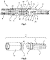
- the Figure 1 shows a contact element 1, which is electrically connected to a cable 2 with an integrated coolant line.
- the contact element 1 consists of a connection part 3 and a contact part 4.
- the connection part 3 contains an axial bore 25 and the contact part 4 contains an axial through bore 26.
- Both the bore 25 and the through bore 26 each contain an internal thread 5 and can be screwed (Not shown) are reversibly connected to each other.
- Knurling 27 is formed on the contact part 4 and prevents twisting between the connecting part 3 and the contact part 4. If the contact part 4 is worn out after many mating cycles, a fresh contact part 4 can be put on without having to reconnect the cable 2 to the contact element 1.
- the cable 2 can remain permanently on the connecting part 3.
- the contact part 4 is designed as a so-called socket with a total of 6 lamellae 7.
- the connecting part 3 is essentially cylindrical.
- a hollow cylinder 6 protrudes axially from the main body.
- the hollow cylinder 6 can also be regarded as a hollow needle.
- the hollow cylinder 6 tapers towards the end and opens into an outlet opening 13.
- a lamellar structure 14 is applied to the hollow cylinder 6 between the outlet opening 13 and the main body.
- Openings 15 are made in the connection part 3, which form an access to a cavity 16 within the connection part 3.
- a plurality of openings 15 are provided rotationally symmetrically along the lateral surface of the connecting part 3.
- the openings 15 are each at the same distance from one another.
- the cavity 16 is also in communication with the cavity which the hollow cylinder 6 forms.
- the cable 2 connected to the contact element 1 consists of a central coolant line 8.
- Individual conductors 9, here copper wires, are positioned around the coolant line 8.
- the copper wires are enclosed by a liquid-tight film 10 (only hinted at for illustrative reasons).
- So-called buffer elements 11 lie on this film 10, which are ultimately enclosed by a fixed cable sheath 12.
- the buffer elements 11 are also hollow, so that a cooling liquid can flow in the area between the liquid-tight film 10 and the cable jacket 12.
- the cable 2 is attached to the contact element 1 via a sleeve 17.
- the connecting part 3 has two circumferential grooves 19, in which each have a sealing ring (not shown for illustrative reasons).
- the sleeve 17 is sealed in a media-tight manner via the sealing rings.
- the outlet opening 13 of the hollow cylinder 6 is inserted into the central coolant line 8 of the cable 2.
- the inside diameter of the coolant line 8 is matched to the outside diameter of the hollow cylinder 6 or the outlet opening 13.
- the geometry of the outlet opening 13 prevents the hollow cylinder 6 from slipping out of the coolant line 8.
- the electrical conductors 9 of the cable 2 rest on the lamella structure 14 of the hollow cylinder 6 in an electrically conductive manner.
- Via a crimp sleeve 18 ( Figure 5 ) the conductors 9 are attached to the hollow cylinder 6.
- the crimp sleeve 18 covers part of the liquid-tight film 10.
- the crimp sleeve 18 seals the main body of the connection part 3 in a liquid-tight manner.
- the conductors 9 are accordingly sealed in a liquid-tight manner.
- the connecting part 3 has a cavity 16 through which cooling liquid can flow.
- the volume of the cavity can be set so that sufficient heat can be dissipated via the cooling liquid, but the connecting part still has sufficient solidity.
- the coolant flows on the cable jacket side along the arrow 20 through the sleeve 17 and from there along the arrow 21 into the openings 15 of the connection part 3.
- the cavity 16 of the connection part 3 is flowed through by the cooling liquid.
- the heat generated here during operation is absorbed by the cooling liquid and transported away again via the central liquid line 8 via the hollow space of the hollow cylinder 6 in the direction of arrow 22.
- the cooling liquid can be cooled down again and returned to the openings 15 in a circuit.
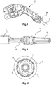
- FIG 8 An open housing of a connector 23 is shown, in which the contact element 1 is installed and connected to a cable 2.
- the plug connector 23 comprises at least two contact elements 1 and also two cables 2 connected to it, which contain a cooling line.
- the plug connector 23 can contain further non-cooled contact elements (not shown), for example for control signals, which are each connected to cables without a cooling function.
- the two cables 2 and other cables are combined in a flexible tube (not shown for illustrative reasons), which goes from the cable outlet 24 of the connector 23.
- the Figure 9 shows an alternative embodiment of the contact element 1 with a connected, coolant-carrying cable 2.
- the crimp sleeve 18 ' is made in two parts. In Figure 9 only a part of the two-part crimp sleeve 18 'is shown for illustrative reasons.
- FIG 10 A special type of crimping of the crimp sleeve 18 is shown.
- the crimp sleeve 18 is brought into a so-called hex-star crimp shape. This ensures a uniform and particularly gas-tight crimping.
- This type of crimping also has very low resistance values.
- the individual conductors 9 are squeezed together under the crimp sleeve 18 and are in contact with one another. This forms a closed, conductive copper layer around the connection part 3.
- the cooling liquid can flow via the crimp sleeve 18 to the contact element 1 or to its connecting part 3.
Landscapes
- Engineering & Computer Science (AREA)
- Power Engineering (AREA)
- Transportation (AREA)
- Mechanical Engineering (AREA)
- Connector Housings Or Holding Contact Members (AREA)
- Details Of Connecting Devices For Male And Female Coupling (AREA)
Description
- Die Erfindung geht aus von einem flüssigkeitsgekühlten Kontaktelement nach dem Oberbegriff des unabhängigen Anspruchs 1. Die Erfindung bezieht sich weiterhin auf einen Steckverbinder, der ein solches Kontaktelement verwendet.
- Derartige Kontaktelemente werden insbesondere zur Übertragung hoher Ströme eingesetzt und beispielsweise in Ladesteckverbindern verwendet.
- Bei Elektrofahrzeugen ist ein schnelles Laden notwendig, wenn sich diese Technik gegenüber herkömmlichen Fahrzeugen mit Verbrennungsmotor durchsetzen soll. Die Fahrzeuge mit Verbrennungsmotor können innerhalb von wenigen Minuten vollgetankt werden. Elektrofahrzeuge müssen hier mithalten können. Bei Schnellladevorgängen müssen besonders hohe Ströme eingesetzt werden, was zu einer starken Hitzeentwicklung bei Ladesteckverbindern führt.
- Die
US 3,244,792 A zeigt ein Kontaktelement 21, 23 für ein Schweißgerät. - Auch die
FR 2 723 466 A1 - Die
DE 10 2010 050 562 B3 zeigt einen Ladesteckverbinder für Elektroautos. Die beim Ladevorgang erzeugte Erwärmung des Steckverbinders wird durch eine spiralförmige Flüssigkeitsleitung verringert, die im Wesentlichen im Griffbereich des Steckverbinders verläuft. Durch die Flüssigkeitsleitung fließt eine Kühlflüssigkeit in einem geschlossenen Kühlkreislauf. - Bei dem beschriebenen Steckverbinder wird lediglich der Steckverbinder gekühlt. Bei den Kontaktelementen und den daran angeschlossenen elektrischen Leitern kann sich im Betrieb nach wie vor Wärme stauen, was zu einem Leistungsverlust des Steckverbinders und damit verbundenen längeren Ladevorgängen führen kann.
- Die Aufgabe der Erfindung besteht darin ein leistungsfähiges Kontaktelement, insbesondere für den Einsatz in Ladesteckverbindern, zu generieren.
- Die Aufgabe wird durch die kennzeichnenden Merkmale des unabhängigen Anspruchs 1 gelöst.
- Vorteilhafte Ausgestaltungen der Erfindung sind in den Unteransprüchen angegeben.
- Das erfindungsgemäße elektrische Kontaktelement ist optimal für den Einsatz in Ladesteckverbindern geeignet. Derartige Ladesteckverbinder werden beispielsweise zum Laden von Elektroautos eingesetzt.
- Das Kontaktelement weist ein Kontaktteil und ein Anschlussteil auf. Das Anschlussteil ist so ausgestaltet, dass es mit einem elektrischen Leiter eines Kabels verbindbar ist. Dem Kontaktelement ist Kühlflüssigkeit zuführbar. Im Anschlussteil des Kontaktelements sind Hohlräume vorhanden in denen Kühlflüssigkeit strömen und dabei Wärme aufnehmen und abführen kann. Das Anschlussteil ist dazu mit einer Zuflussleitung für Kühlflüssigkeit verbindbar. Der elektrische Leiter und die Zuflussleitung können am Kontaktelement angeschlossen werden.
- Vorteilhafterweise ist das elektrische Kontaktelement zumindest zweiteilig ausgeführt. Das Anschlussteil und das Kontaktteil werden jeweils von separaten Bauteilen gebildet. Die separaten Bauteile sind reversibel miteinander verbindbar.
- Die Zweiteiligkeit hat den Vorteil, dass das Kontaktteil nach einer bestimmten Anzahl von Steckzyklen ausgewechselt werden kann, während das Anschlussteil weiter benutzt werden kann. Ein Steckverbinder ist durch den Austausch der Kontaktteile wieder sehr schnell einsetzbar. Ein weiterer Vorteil dieser Bauweise besteht darin, dass das Anschlussteil und das Kontaktteil aus verschiedenen Werkstoffen gebildet sein können. Die Werkstoffe können je nach Bedürfnis gewählt werden. Beispielsweise kann das Kontaktteil mit einer besonders gut leitenden Beschichtung, beispielsweise mit einer Silber- oder Goldlegierung, versehen sein. Für das Anschlussteil ist eine derartige Beschichtung nicht notwendig. Hier kann diese entsprechend entfallen.
- In einer vorteilhaften Ausführungsform der Erfindung können das Anschlussteil und das Kontaktteil miteinander verschraubbar ausgeführt sein. Dadurch ist es möglich ein durch diverse Steckzyklen verschlissenes Kontaktteil steckseitig aus dem Steckverbinder zu entfernen und durch ein neues Kontaktteil zu ersetzen.
- Vorzugsweise ist das Kontaktteil des Kontaktelements als so genannte Buchse mit bevorzugt vier oder sechs Lamellen ausgebildet. Das Anschlussteil ist im Wesentlichen zylinderförmig ausgebildet und weist einen davon axial abstehenden Hohlzylinder auf. In das Anschlussteil ist zumindest eine Öffnung, bevorzugt sind jedoch zwei, drei oder vier Öffnungen, eingebracht.
- In einer vorteilhaften Variante der Erfindung sind der Hohlraum der Öffnung oder die Hohlräume der Öffnungen mit dem Hohlraum des Hohlzylinders verbunden. In die Öffnung oder in die Öffnungen des Anschlussteils ist Kühlflüssigkeit einströmbar und durch den Hohlzylinder kann die Kühlflüssigkeit wieder ausströmen. Die Kühlflüssigkeit kann hier direkt auf das Kontaktelement einwirken. Die Kühlwirkung tritt genau dort ein wo auch die Wärme im Betrieb entsteht. Daher ist die hier gezeigte Kühlung des Kontaktelements auch besonders effektiv, insbesondere dann, wenn das Kontaktelement in einem Ladesteckverbinder für Elektrofahrzeuge eingesetzt wird. Derartige Ladesteckverbinder benötigen keine zusätzliche Kühlung.
- Das am erfindungsgemäßen Kontaktelement angeschlossene Kabel besteht im Querschnitt aus einer zentralen Kühlflüssigkeitsleitung. Um die Kühlflüssigkeitsleitung herum sind einzelne Leiter, hier Kupferadern, positioniert. Die Kupferadern werden von einer flüssigkeitsdichten Folie umschlossen. Auf dieser Folie liegen so genannte Pufferelemente auf, die letztendlich von einem festen Kabelmantel umschlossen sind. Die Pufferelemente sind ebenfalls hohl, so dass im Bereich zwischen flüssigkeitsdichter Folie und Kabelmantel eine Kühlflüssigkeit strömen kann.
- Der Hohlzylinder verjüngt sich endseitig und weist eine Austrittsöffnung auf. Aufwärts von der Austrittsöffnung gesehen ist auf dem Hohlzylinder eine kontinuierliche Lamellenstruktur aufgebracht. Die Lamellenstruktur dient einer gut leitenden Kontaktierung zwischen einem Leiter und dem Kontaktelement.
- Die Austrittsöffnung des Hohlzylinders wird in die zentrale Kühlflüssigkeitsleitung eingeschoben. Der Außendurchmesser der Austrittsöffnung und der Innendurchmesser der zentralen Kühlflüssigkeitsleitung sind dazu aufeinander abgestimmt.
- Auf die Lamellenstruktur des Hohlzylinders sind die einzelnen Leiter des oben beschriebenen Kabels gelegt. Mithilfe einer Crimphülse werden die Leiter auf die Lamellenstruktur festgepresst. Die Lamellenstruktur sorgt für eine besonders gut leitende Verbindung von den Leitern mit dem Anschlussteil.
- Das Kontaktelement weist eine Hülse auf, die einseitig zumindest teilweise das Anschlussteil überdeckt. Im Anschlussteil sind zwei umlaufende Nuten eingebracht, in denen jeweils ein Dichtungsring eingelegt ist. Durch die Dichtungen wird der Überlappungsbereich von Hülse und Anschlussteil mediendicht abgedichtet. Das andere Ende der Hülse verläuft auf dem Kabelmantel des Kabels. Der Innendurchmesser der Hülse und der Außendurchmesser des Kabels sind aufeinander abgestimmt. Über eine Quetschung der Hülse kann der Überlappungsbereich von Hülse und Kabel mediendicht abgedichtet werden.
- Die Kühlung des erfindungsgemäßen Kontaktelements verläuft wie folgt: Die im Bereich der Pufferelemente strömende Kühlflüssigkeit gelangt zum Anschlussteil des Kontaktelements und tritt in die Öffnung oder in die Öffnungen in diesem Bereich in das Kontaktelement ein. Die Flüssigkeit ist in der Lage Wärmeenergie aufzunehmen. Über den Hohlzylinder tritt die Kühlflüssigkeit wieder aus dem Anschlussteil heraus und wird über die zentrale Kühlflüssigkeitsleitung des Kabels wieder abgeführt. Bei dem hier beschriebenen Kühlvorgang handelt es sich um einen Kreisprozess. Das Kontaktelement wird permanent mit frischer Kühlflüssigkeit umspült.
- Ein Ausführungsbeispiel der Erfindung ist in den Zeichnungen dargestellt und wird im Folgenden näher erläutert. Es zeigen:
- Fig. 1
- eine perspektivische Schnittdarstellung eines Kontaktelements mit einem angeschlossenen Kabel,
- Fig. 2
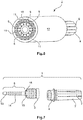
- eine perspektivische Explosionszeichnung des Kontaktelements mit einer Hülse auf dem Anschlussteil,
- Fig. 3
- eine perspektivische Darstellung eines Kontaktteils des Kontaktelements,
- Fig. 4
- eine perspektivische Darstellung eines Anschlussteils des Kontaktelements,
- Fig. 5
- eine perspektivische Darstellung einer Crimphülse,
- Fig. 6
- eine perspektivische Darstellung eines Kabels mit einer integrierten Kühlflüssigkeitsleitung,
- Fig. 7
- eine perspektivische Explosionszeichnung des Kontaktelements,
- Fig. 8
- eine perspektivische Schnittdarstellung eines Steckverbinders mit integriertem Kontaktelement,
- Fig. 9
- eine perspektivische Darstellung des Kontaktelements mit angeschlossenem Kabel und einer zweiteiligen Crimphülse und
- Fig. 10
- eine Schnittdarstellung des Anschlussteils.
- Die Figuren enthalten teilweise vereinfachte, schematische Darstellungen. Zum Teil werden für gleiche, aber gegebenenfalls nicht identische Elemente identische Bezugszeichen verwendet. Verschiedene Ansichten gleicher Elemente könnten unterschiedlich skaliert sein.
- Die
Figur 1 zeigt ein Kontaktelement 1, welches an ein Kabel 2 mit einer integrierten Kühlflüssigkeitsleitung elektrisch angeschlossen ist. Das Kontaktelement 1 besteht aus einem Anschlussteil 3 und einem Kontaktteil 4. Das Anschlussteil 3 enthält eine axiale Bohrung 25 und das Kontaktteil 4 enthält eine axiale Durchgangsbohrung 26. Sowohl die Bohrung 25 wie auch die Durchgangsbohrung 26 enthalten jeweils ein Innengewinde 5 und können über eine Schraube (nicht gezeigt) miteinander reversibel verbunden werden. Am Kontaktteil 4 ist eine Rändelung 27 angeformt, die eine Verdrehung zwischen Anschlussteil 3 und Kontaktteil 4 verhindert. Ist das Kontaktteil 4 nach vielen Steckzyklen verschlissen, kann ein frisches Kontaktteil 4 aufgesetzt werden, ohne das Kabel 2 erneut an das Kontaktelement 1 anschließen zu müssen. Das Kabel 2 kann permanent am Anschlussteil 3 verbleiben. - Das Kontaktteil 4 ist als so genannte Buchse mit insgesamt 6 Lamellen 7 ausgebildet. Das Anschlussteil 3 ist im Wesentlichen zylinderförmig ausgestaltet. Vom Hauptkörper axial abstehend ist ein Hohlzylinder 6 angeformt. Der Hohlzylinder 6 kann auch als Hohlnadel angesehen werden. Der Hohlzylinder 6 verjüngt sich zum Ende hin und mündet in einer Austrittsöffnung 13. Zwischen Austrittsöffnung 13 und Hauptkörper ist auf dem Hohlzylinder 6 eine Lamellenstruktur 14 aufgebracht. Im Anschlussteil 3 sind Öffnungen 15 eingebracht, die einen Zugang zu einem Hohlraum 16 innerhalb des Anschlussteils 3 bilden. Es sind mehrere Öffnungen 15 rotationssymmetrisch entlang der Mantelfläche des Anschlussteils 3 vorgesehen. Die Öffnungen 15 haben jeweils den gleichen Abstand zueinander. Der Hohlraum 16 steht ebenfalls in Verbindung mit dem Hohlraum, den der Hohlzylinder 6 bildet.
- Das am Kontaktelement 1 angeschlossene Kabel 2 besteht im Querschnitt aus einer zentralen Kühlflüssigkeitsleitung 8. Um die Kühlflüssigkeitsleitung 8 herum sind einzelne Leiter 9, hier Kupferadern, positioniert. Die Kupferadern werden von einer flüssigkeitsdichten Folie 10 (aus darstellerischen Gründen nur angedeutet) umschlossen. Auf dieser Folie 10 liegen so genannte Pufferelemente 11 auf, die letztendlich von einem festen Kabelmantel 12 umschlossen sind. Die Pufferelemente 11 sind ebenfalls hohl ausgestaltet, so dass im Bereich zwischen flüssigkeitsdichter Folie 10 und Kabelmantel 12 eine Kühlflüssigkeit strömen kann. Das Kabel 2 wird über eine Hülse 17 am Kontaktelement 1 befestigt. Das Anschlussteil 3 weist zwei umlaufende Nuten 19 auf, in denen jeweils ein Dichtring (aus darstellerischen Gründen nicht gezeigt) angeordnet ist. Über die Dichtringe ist die Hülse 17 mediendicht abgedichtet.
- Die Austrittsöffnung 13 des Hohlzylinders 6 wird in die zentrale Kühlflüssigkeitsleitung 8 des Kabels 2 eingeschoben. Der Innendurchmesser der Kühlflüssigkeitsleitung 8 ist auf den Außendurchmesser des Hohlzylinders 6 bzw. der Austrittsöffnung 13 abgestimmt. Die Geometrie der Austrittsöffnung 13 verhindert ein Hinausrutschen des Hohlzylinders 6 aus der Kühlflüssigkeitsleitung 8. Auf der Lamellenstruktur 14 des Hohlzylinders 6 liegen die elektrischen Leiter 9 des Kabels 2 elektrisch leitend an. Über eine Crimphülse 18 (
Figur 5 ) werden die Leiter 9 auf dem Hohlzylinder 6 befestigt. Zum Kabel 2 hin überdeckt die Crimphülse 18 einen Teil der flüssigkeitsdichten Folie 10. Zum anderen Ende dichtet die Crimphülse 18 flüssigkeitsdicht zum Hauptkörper des Anschlussteils 3 ab. Die Leiter 9 sind demnach flüssigkeitsdicht abgedichtet. - Das Anschlussteil 3 weist einen von Kühlflüssigkeit durchströmbaren Hohlraum 16 auf. Das Volumen des Hohlraums kann so eingestellt werden, dass ausreichend Wärme über die Kühlflüssigkeit abführbar ist, das Anschlussteil aber noch eine ausreichende Massivität aufweist.
- Die Kühlflüssigkeit fließt kabelmantelseitig entlang des Pfeils 20 durch die Hülse 17 und von dort aus entlang des Pfeils 21 in die Öffnungen 15 des Anschlussteils 3 ein. Der Hohlraum 16 des Anschlussteils 3 wird von der Kühlflüssigkeit durchströmt. Die im Betrieb hier entstandene Wärme wird von der Kühlflüssigkeit aufgenommen und über den Hohlraum des Hohlzylinders 6 in Richtung des Pfeils 22 über die zentrale Flüssigkeitsleitung 8 wieder abtransportiert. In einem entfernten System kann die Kühlflüssigkeit wieder runtergekühlt und in einem Kreislauf wieder den Öffnungen 15 zugeführt werden.
- In
Figur 8 ist ein geöffnetes Gehäuse eines Steckverbinders 23 gezeigt, in dem das Kontaktelement 1 eingebaut und an ein Kabel 2 angeschlossen ist. In der Regel umfasst der Steckverbinder 23 zumindest zwei Kontaktelemente 1 und auch zwei daran angeschlossene Kabel 2, die eine Kühlleitung enthalten. Der Steckverbinder 23 kann weitere nicht gekühlte Kontaktelemente (nicht gezeigt), beispielsweise für Steuersignale, enthalten, die jeweils an Kabel ohne Kühlfunktion angeschlossen sind. Die beiden Kabel 2 und weitere Kabel werden in einem flexiblen Rohr (aus darstellerischen Gründen nicht gezeigt) vereint, welches vom Kabelabgang 24 des Steckverbinders 23 abgeht. - Die
Figur 9 zeigt eine alternative Ausführungsform des Kontaktelements 1 mit einem angeschlossenen, kühlflüssigkeitsführenden Kabel 2. Hier ist die Crimphülse 18' zweiteilig ausgeführt. InFigur 9 ist aus darstellerischen Gründen nur ein Teil der zweiteiligen Crimphülse 18' gezeigt. - In
Figur 10 ist eine besondere Art der Vercrimpung der Crimphülse 18 dargestellt. Die Crimphülse 18 wird in eine so genannte Hex-Stern-Crimpform gebracht. Dadurch wird eine gleichmäßige und besonders gasdichte Vercrimpung erreicht. Diese Art der Vercrimpung weist außerdem sehr niedrige Widerstandswerte auf. Die einzelnen Leiter 9 werden unter der Crimphülse 18 zusammengequetscht und stehen in einem Berührkontakt untereinander. Dadurch bildet sich eine geschlossene, leitende Kupferschicht um das Anschlussteil 3 herum. Im Bereich der Pufferelemente 11 kann die Kühlflüssigkeit über die Crimphülse 18 zum Kontaktelement 1 bzw. zu dessen Anschlussteil 3 strömen. -
1 Kontaktelement 15 Öffnungen 2 Kabel 16 Hohlraum 3 Anschlussteil 17 Hülse 4 Kontaktteil 18 Crimphülse 5 Innengewinde 19 Nut 6 Hohlzylinder 20 Pfeil 7 Lamelle 21 Pfeil 8 Zentrale 22 Pfeil Kühlflüssigkeitsleitung 9 Leiter 23 Steckverbinder 10 Flüssigkeitsdichte 24 Kabelabgang Folie 11 Pufferelement 25 Bohrung 12 Kabelmantel 26 Durchgangsbohrung 13 Austrittsöffnung 27 Rändelung 14 Lamellenstruktur
Claims (12)
- Elektrisches Kontaktelement (1), welches ein Kontäktteil (4) und ein Anschlussteil (3) aufweist, wobei das Anschlussteil (3) mit einem elektrischen Leiter (9) eines Kabels (2) verbindbar ist, wobei dem Kontaktelement (1) Kühlflüssigkeit zuführbar ist, wobei das elektrische Kontaktelement (1) zumindest zweiteilig ausgeführt ist, und das Anschlussteil (3) und das Kontaktteil (4) jeweils als separate Bauteile ausgeführt sind, die reversibel miteinander verbindbar sind und das Anschlussteil (3) einen von Kühlflüssigkeit durchströmbaren Hohlraum (16) aufweist, wobei das Anschlussteil (3) im Wesentlichen zylinderförmig ausgebildet ist und einen Hohlzylinder (6) aufweist, dadurch gekennzeichnet, dass der Hohlzylinder (6) endseitig eine Austrittsöffnung (13) aufweist und sich zum Ende hin verjüngt und in der Austrittsöffnung (13) mündet und dass auf dem Hohlzylinder (6) eine Lamellenstruktur (14) aufgebracht ist.
- Elektrisches Kontaktelement nach vorstehendem Anspruch dadurch gekennzeichnet, dass das Anschlussteil (3) und das Kontaktteil (4) miteinander verschraubbar sind.
- Elektrisches Kontaktelement nach einem der vorstehenden Ansprüche dadurch gekennzeichnet, dass das Kontaktteil (4) als Buchse ausgebildet ist.
- Elektrisches Kontaktelement nach vorstehendem Anspruch
dadurch gekennzeichnet, dass
die Buchse vier oder sechs Lamellen (7) aufweist. - Elektrisches Kontaktelement nach einem der vorstehenden Ansprüche
dadurch gekennzeichnet, dass
das Anschlussteil (3) zumindest eine Öffnung (15) aufweist. - Elektrisches Kontaktelement nach vorstehendem Anspruch
dadurch gekennzeichnet, dass
das Anschlussteil (3) zwei, drei oder vier Öffnungen (15) aufweist. - Elektrisches Kontaktelement nach einem der beiden vorstehenden Ansprüche
dadurch gekennzeichnet, dass
der Hohlraum (16) den die Öffnung (15) erschließt oder den die Öffnungen (15) erschließen mit dem Hohlraum des Hohlzylinders (6) verbunden ist. - Elektrisches Kontaktelement nach einem der drei vorstehenden Ansprüche
dadurch gekennzeichnet, dass
in die Öffnung (15) oder in die Öffnungen (15) des Anschlussteils (3) Kühlflüssigkeiteinströmbar und durch den Hohlzylinder (6) die Kühlflüssigkeit wieder ausströmbar ist. - Elektrisches Kontaktelement nach einem der vorstehenden Ansprüche
dadurch gekennzeichnet, dass
das Kontaktelement (1) eine Hülse (17) aufweist, die zumindest teilweise das Anschlussteil (3) überdeckt. - Steckverbinder mit zumindest einem elektrischen Kontaktelement (1) nach einem der vorstehenden Ansprüche.
- Steckverbinder nach vorstehendem Anspruch,
dadurch gekennzeichnet, dass
es sich beim Steckverbinder um einen Autoladesteckverbinder handelt. - Steckverbinder nach einem der beiden vorstehenden Ansprüche, dadurch gekennzeichnet, dass
am Kontaktelement (1) zumindest ein kühlflüssigkeitsführendes Kabel (2) angeschlossen ist.
Applications Claiming Priority (2)
| Application Number | Priority Date | Filing Date | Title |
|---|---|---|---|
| DE102016112306.4A DE102016112306A1 (de) | 2016-07-05 | 2016-07-05 | Flüssigkeitsgekühltes Kontaktelement |
| PCT/DE2017/100550 WO2018006903A1 (de) | 2016-07-05 | 2017-06-30 | Flüssigkeitsgekühltes kontaktelement |
Publications (2)
| Publication Number | Publication Date |
|---|---|
| EP3482462A1 EP3482462A1 (de) | 2019-05-15 |
| EP3482462B1 true EP3482462B1 (de) | 2020-08-05 |
Family
ID=59501125
Family Applications (1)
| Application Number | Title | Priority Date | Filing Date |
|---|---|---|---|
| EP17745974.0A Active EP3482462B1 (de) | 2016-07-05 | 2017-06-30 | Flüssigkeitsgekühltes kontaktelement |
Country Status (7)
| Country | Link |
|---|---|
| US (1) | US10632861B2 (de) |
| EP (1) | EP3482462B1 (de) |
| JP (1) | JP6738441B2 (de) |
| KR (1) | KR102174180B1 (de) |
| CN (1) | CN109417237B (de) |
| DE (1) | DE102016112306A1 (de) |
| WO (1) | WO2018006903A1 (de) |
Families Citing this family (34)
| Publication number | Priority date | Publication date | Assignee | Title |
|---|---|---|---|---|
| KR100697308B1 (ko) * | 2004-12-09 | 2007-03-20 | 한국생명공학연구원 | 신규 카탈라아제 프로모터 및 이를 이용한 재조합 단백질생산 방법 |
| DE102016117011A1 (de) * | 2016-09-09 | 2018-03-15 | Itt Manufacturing Enterprises Llc | Elektrisch leitfähiges Kontaktelement für einen elektrischen Steckverbinder |
| DE102017115241A1 (de) * | 2017-07-07 | 2019-01-10 | Paxos Consulting & Engineering GmbH & Co. KG | Ladekabelsystem mit Kühlung |
| DE102017129281A1 (de) * | 2017-12-08 | 2019-06-13 | HARTING Automotive GmbH | Flüssigkeitsgekühltes Kontaktelement |
| DE102018102207A1 (de) * | 2018-02-01 | 2019-08-01 | Dr. Ing. H.C. F. Porsche Aktiengesellschaft | Kraftfahrzeugladekabel |
| DE102018122680B3 (de) * | 2018-09-17 | 2020-02-20 | Dr. Ing. H.C. F. Porsche Aktiengesellschaft | Kraftfahrzeugladekabel |
| DE102018123455A1 (de) | 2018-09-24 | 2020-03-26 | HARTING Automotive GmbH | Flüssigkeitsgekühlter Kabelaufbau |
| CN109334485B (zh) * | 2018-09-30 | 2021-11-12 | 东莞市日新传导科技有限公司 | 液冷连接器 |
| CH715611B1 (de) | 2018-12-05 | 2022-05-13 | BRUGG eConnect AG | Anschlusselement zum elektrischen Anschliessen einer fluidkühlbaren Einzelleitung, fluidkühlbare Einzelleitungseinheit und Ladekabel. |
| DE102019101979A1 (de) | 2019-01-28 | 2020-07-30 | HARTING Automotive GmbH | Zugentlastung für einen Kabelschlauch |
| US10756498B1 (en) * | 2019-03-22 | 2020-08-25 | Te Connectivity Corporation | Terminal heat exchanger for an electrical connector |
| US10988041B2 (en) * | 2019-03-27 | 2021-04-27 | Te Connectivity Corporation | Cable heat exchanger for a power connector |
| CN110048282A (zh) * | 2019-05-31 | 2019-07-23 | 南京康尼机电股份有限公司 | 一种用于电动汽车的插座及采用其的电动汽车 |
| EP3770005B8 (de) | 2019-07-25 | 2023-12-06 | ABB E-mobility B.V. | Elektrofahrzeugladesystem zum laden eines elektrofahrzeugs |
| US11846475B2 (en) * | 2019-08-26 | 2023-12-19 | Te Connectivity Solutions Gmbh | Heat exchanger for a power connector |
| KR102844104B1 (ko) | 2019-11-27 | 2025-08-07 | 엘에스이브이코리아 주식회사 | 전기차 충전용 커넥터 및 이를 포함하는 전기차 충전용 어셈블리 |
| DE102019132390A1 (de) * | 2019-11-28 | 2021-06-02 | Amphenol Tuchel Industrial GmbH | Kontaktanordnung für Steckverbindungen, Ladestecker mit Kühlungseinrichtung |
| JP6933270B2 (ja) * | 2020-01-10 | 2021-09-08 | トヨタ自動車株式会社 | 評価治具 |
| CN111200200B (zh) * | 2020-01-20 | 2021-02-09 | 洛阳正奇机械有限公司 | 一种新能源电动汽车液冷充电插座用液冷线缆 |
| DE102020104168B4 (de) | 2020-02-18 | 2022-01-27 | Dr. Ing. H.C. F. Porsche Aktiengesellschaft | Steckervorrichtung |
| US11951857B2 (en) * | 2020-11-04 | 2024-04-09 | Ford Global Technologies, Llc | Liquid cooled electrical connectors |
| EP4112366B1 (de) | 2021-06-30 | 2026-01-28 | ABB E-mobility B.V. | Ladestecker für ein elektrofahrzeug |
| EP4134265A1 (de) | 2021-08-13 | 2023-02-15 | ABB E-mobility B.V. | Ladesystem für ein elektrofahrzeug |
| EP4134266B1 (de) | 2021-08-13 | 2024-10-02 | ABB E-mobility B.V. | Ladesystem für ein elektrofahrzeug |
| EP4151453A1 (de) * | 2021-09-21 | 2023-03-22 | ABB E-mobility B.V. | Kontaktelement für einen ev-stecker mit kapillarflüssigkeitskühlung |
| EP4151454A1 (de) | 2021-09-21 | 2023-03-22 | ABB E-mobility B.V. | Kontaktelementanordnung für einen ev-steckverbinder mit einem wärmerohr |
| US12155141B2 (en) * | 2021-12-02 | 2024-11-26 | Caterpillar Inc. | Connector assembly having a cable connected charging pin and socket in fluid communication with one another |
| DE102022122135B4 (de) * | 2022-09-01 | 2026-03-05 | Leoni Kabel Gmbh | Energieversorgungssystem für eine elektrisch angetriebene Maschine mit einem innengekühlten Kabel |
| CA3195182A1 (en) * | 2022-11-25 | 2024-05-25 | Suzhou Yihang Electronic Technology Co., Ltd. | A quick-change structure for liquid-cooled charging gun |
| DE102023131125A1 (de) | 2023-11-09 | 2025-05-15 | Amphenol-Tuchel Electronics Gesellschaft mit beschränkter Haftung | Steckverbinderstecker mit zirkularer Kühlmediumführung |
| DE102024129357A1 (de) * | 2024-10-10 | 2026-04-16 | Te Connectivity Solutions Gmbh | Busbar-Einheit |
| DE202024106342U1 (de) * | 2024-11-06 | 2025-10-14 | PTR HARTMANN GmbH | Montagehülse für einen Federkontaktstift und Federkontaktvorrichtung |
| DE102024132441A1 (de) * | 2024-11-07 | 2026-05-07 | Leoni Bordnetz-Systeme Gmbh | Kabelschuh für gekühlte Hochvoltleitungen |
| CN119502740B (zh) * | 2025-01-21 | 2025-05-16 | 苏州智绿科技股份有限公司 | 液冷端子及充电枪 |
Family Cites Families (23)
| Publication number | Priority date | Publication date | Assignee | Title |
|---|---|---|---|---|
| US2366747A (en) * | 1943-07-19 | 1945-01-09 | Glenn S Noble | Cable connector |
| US3210720A (en) * | 1961-04-28 | 1965-10-05 | James C Julian | Cable connectors |
| NL124000C (de) * | 1962-04-06 | |||
| DE1540860B1 (de) * | 1963-03-12 | 1972-05-25 | Kjellberg Esab Gmbh | Biegsame vorrichtung zur zufuhr von schweissdraht, schweisstrom, schutzgas und druckgas an eine schweisspistole |
| US3610875A (en) * | 1970-02-11 | 1971-10-05 | Unitec Corp | Apparatus for conducting gas and electrical current |
| FR2723466B1 (fr) * | 1994-08-03 | 1996-09-13 | Cogema | Guirlande de connexion pour l'alimentation d'un appareil mobile |
| JPH10108376A (ja) * | 1996-08-07 | 1998-04-24 | Sumitomo Wiring Syst Ltd | 電気自動車用充電システム |
| US6077132A (en) * | 1998-10-26 | 2000-06-20 | Wpi/Viking | Electrical connector with replaceable pin contacts not requiring accompanying re-termination |
| DE19916984C1 (de) * | 1999-04-15 | 2000-07-13 | Raymond A & Cie | Steckverbindung für wassergekühlte, stromführende Leitungen an Werkzeugen und anderen Geräten |
| US6328615B1 (en) * | 2000-03-02 | 2001-12-11 | Itt Manufacturing Enterprises, Inc. | Contact formed of joined pieces |
| JP2005056770A (ja) * | 2003-08-07 | 2005-03-03 | Inoue Seisakusho:Kk | コネクタ |
| US7511245B2 (en) * | 2005-09-12 | 2009-03-31 | Nelson Stud Welding, Inc. | Stud welding apparatus with composite cable |
| EP2104183A1 (de) * | 2008-03-18 | 2009-09-23 | ABB Schweiz AG | Elektrische Verbindungseinrichtung und Verbinder |
| US8288986B2 (en) | 2008-04-28 | 2012-10-16 | Aerovironment Inc. | Concentric connector for electric vehicles |
| WO2012051510A2 (en) * | 2010-10-14 | 2012-04-19 | Gregory Thomas Mark | Actively cooled electrical connection |
| DE102010050562B3 (de) | 2010-11-05 | 2012-04-05 | Volkswagen Aktiengesellschaft | Vorrichtung zum Laden eines mit elektrischer Energie antreibbaren Fahrzeugs |
| US9325095B2 (en) * | 2011-05-05 | 2016-04-26 | Lear Corporation | Female type contact for an electrical connector |
| CN202523938U (zh) | 2012-04-17 | 2012-11-07 | 李大囡 | 中空水冷电缆 |
| US9321362B2 (en) * | 2014-02-05 | 2016-04-26 | Tesia Motors, Inc. | Cooling of charging cable |
| CN204760561U (zh) | 2015-05-22 | 2015-11-11 | 江苏国红金属材料有限公司 | 一种水冷电缆用铜排 |
| DE102015112347A1 (de) * | 2015-07-29 | 2017-02-02 | Dr. Ing. H.C. F. Porsche Aktiengesellschaft | Ladestation mit einem Ladekabel |
| DE102016105470A1 (de) * | 2016-03-23 | 2017-09-28 | Te Connectivity Germany Gmbh | Leistungselektrische Kontakteinrichtung; austauschbares, leistungselektrisches Kontaktmodul sowie leistungselektrischer Verbinder |
| DE102016117261B3 (de) * | 2016-09-14 | 2017-11-30 | HARTING Automotive GmbH | System aus einem Steckverbinder, einem fluidgekühlten Kabel und einer Anschlusseinheit |
-
2016
- 2016-07-05 DE DE102016112306.4A patent/DE102016112306A1/de not_active Ceased
-
2017
- 2017-06-30 JP JP2018562314A patent/JP6738441B2/ja active Active
- 2017-06-30 EP EP17745974.0A patent/EP3482462B1/de active Active
- 2017-06-30 CN CN201780041914.4A patent/CN109417237B/zh active Active
- 2017-06-30 KR KR1020197003056A patent/KR102174180B1/ko active Active
- 2017-06-30 US US16/305,836 patent/US10632861B2/en active Active
- 2017-06-30 WO PCT/DE2017/100550 patent/WO2018006903A1/de not_active Ceased
Non-Patent Citations (1)
| Title |
|---|
| None * |
Also Published As
| Publication number | Publication date |
|---|---|
| US10632861B2 (en) | 2020-04-28 |
| WO2018006903A1 (de) | 2018-01-11 |
| US20190315239A1 (en) | 2019-10-17 |
| CN109417237A (zh) | 2019-03-01 |
| EP3482462A1 (de) | 2019-05-15 |
| DE102016112306A1 (de) | 2018-01-11 |
| CN109417237B (zh) | 2020-12-25 |
| KR102174180B1 (ko) | 2020-11-04 |
| JP6738441B2 (ja) | 2020-08-12 |
| JP2019517714A (ja) | 2019-06-24 |
| KR20190022850A (ko) | 2019-03-06 |
Similar Documents
| Publication | Publication Date | Title |
|---|---|---|
| WO2018006903A1 (de) | Flüssigkeitsgekühltes kontaktelement | |
| EP3891851B1 (de) | Anschlusselement zum elektrischen anschliessen einer fluidkühlbaren einzelleitung, fluidkühlbare einzelleitungseinheit und ladekabel | |
| DE102016117261B3 (de) | System aus einem Steckverbinder, einem fluidgekühlten Kabel und einer Anschlusseinheit | |
| EP3521100B1 (de) | Kraftfahrzeugladekabel | |
| EP3433902B1 (de) | Steckverbinderteil mit einem gekühlten kontaktelement | |
| EP3465699B1 (de) | Ladekabel zur übertragung elektrischer energie, ladestecker und ladestation zur abgabe elektrischer energie an einen empfänger elektrischer energie | |
| EP3043421B1 (de) | Elektroanschlusskörper für einen ladestecker und/oder eine ladebuchse, ladestecker und ladestation zur abgabe elektrischer energie an einen empfänger elektrischer energie | |
| EP3624141B1 (de) | Kühlbare einzelleitung und ladekabel | |
| EP3628533A1 (de) | Flüssigkeitsgekühlter kabelaufbau und verfahren zum kühlen eines kabelaufbaus | |
| EP3330976A1 (de) | Hochstromkabel und stromversorgungssystem mit hochstromkabel | |
| DE112006002398T5 (de) | Fahrzeugleiter | |
| DE102017120725A1 (de) | Entwärmungsvorrichtung für eine elektrische leitung, damit ausgestattete leitungsanordnung und verfahren zum entwärmen einer elektrischen leitung | |
| DE102007007761A1 (de) | Scheiben-oder Scheinwerferwaschanlage eines Fahrzeuges und ein Fluidzuführschlauch hierfür | |
| DE102018202128A1 (de) | Elektrische Verbindungseinheit und Batteriesystem | |
| DE112006000815T5 (de) | Abgeschirmter Leiter und Herstellungsverfahren dafür | |
| WO2021105196A1 (de) | Kontaktanordnung für steckverbindungen, ladestecker mit kühlungseinrichtung | |
| DE10197076B4 (de) | Abschlußmuffe für Mineralisoliertes Kabel | |
| EP1699116B1 (de) | Steckverbinder mit einer Crimp-Abdichtung und/oder einer Kabelhalterung | |
| DE102018010632B4 (de) | Heizpatrone mit Temperatursensor | |
| DE202016008631U1 (de) | Flüssigkeitsgekühltes Kontaktelement | |
| DE102017129281A1 (de) | Flüssigkeitsgekühltes Kontaktelement | |
| DE19911253A1 (de) | Elektrisches Verbindungsstück | |
| EP2988374B1 (de) | Dichtelement für eine elektrische leitung mit litzenleiter | |
| EP3382255B1 (de) | Rohrleitung umfassend einen verbinder sowie verfahren zum betrieb dieser rohrleitung | |
| DE102010000822B4 (de) | Kabelverbindungseinheit |
Legal Events
| Date | Code | Title | Description |
|---|---|---|---|
| STAA | Information on the status of an ep patent application or granted ep patent |
Free format text: STATUS: UNKNOWN |
|
| STAA | Information on the status of an ep patent application or granted ep patent |
Free format text: STATUS: THE INTERNATIONAL PUBLICATION HAS BEEN MADE |
|
| PUAI | Public reference made under article 153(3) epc to a published international application that has entered the european phase |
Free format text: ORIGINAL CODE: 0009012 |
|
| STAA | Information on the status of an ep patent application or granted ep patent |
Free format text: STATUS: REQUEST FOR EXAMINATION WAS MADE |
|
| 17P | Request for examination filed |
Effective date: 20181122 |
|
| AK | Designated contracting states |
Kind code of ref document: A1 Designated state(s): AL AT BE BG CH CY CZ DE DK EE ES FI FR GB GR HR HU IE IS IT LI LT LU LV MC MK MT NL NO PL PT RO RS SE SI SK SM TR |
|
| AX | Request for extension of the european patent |
Extension state: BA ME |
|
| DAX | Request for extension of the european patent (deleted) | ||
| DAV | Request for validation of the european patent (deleted) | ||
| GRAP | Despatch of communication of intention to grant a patent |
Free format text: ORIGINAL CODE: EPIDOSNIGR1 |
|
| STAA | Information on the status of an ep patent application or granted ep patent |
Free format text: STATUS: GRANT OF PATENT IS INTENDED |
|
| RIC1 | Information provided on ipc code assigned before grant |
Ipc: H01R 13/00 20060101AFI20200325BHEP Ipc: H01R 4/56 20060101ALI20200325BHEP Ipc: B60L 53/18 20190101ALI20200325BHEP Ipc: B60L 53/16 20190101ALI20200325BHEP Ipc: H01R 13/11 20060101ALI20200325BHEP Ipc: H01R 13/533 20060101ALI20200325BHEP |
|
| INTG | Intention to grant announced |
Effective date: 20200409 |
|
| GRAS | Grant fee paid |
Free format text: ORIGINAL CODE: EPIDOSNIGR3 |
|
| GRAA | (expected) grant |
Free format text: ORIGINAL CODE: 0009210 |
|
| STAA | Information on the status of an ep patent application or granted ep patent |
Free format text: STATUS: THE PATENT HAS BEEN GRANTED |
|
| AK | Designated contracting states |
Kind code of ref document: B1 Designated state(s): AL AT BE BG CH CY CZ DE DK EE ES FI FR GB GR HR HU IE IS IT LI LT LU LV MC MK MT NL NO PL PT RO RS SE SI SK SM TR |
|
| REG | Reference to a national code |
Ref country code: GB Ref legal event code: FG4D Free format text: NOT ENGLISH |
|
| REG | Reference to a national code |
Ref country code: CH Ref legal event code: EP |
|
| REG | Reference to a national code |
Ref country code: AT Ref legal event code: REF Ref document number: 1300033 Country of ref document: AT Kind code of ref document: T Effective date: 20200815 |
|
| REG | Reference to a national code |
Ref country code: IE Ref legal event code: FG4D Free format text: LANGUAGE OF EP DOCUMENT: GERMAN |
|
| REG | Reference to a national code |
Ref country code: DE Ref legal event code: R096 Ref document number: 502017006620 Country of ref document: DE |
|
| REG | Reference to a national code |
Ref country code: LT Ref legal event code: MG4D |
|
| REG | Reference to a national code |
Ref country code: NL Ref legal event code: MP Effective date: 20200805 |
|
| PG25 | Lapsed in a contracting state [announced via postgrant information from national office to epo] |
Ref country code: FI Free format text: LAPSE BECAUSE OF FAILURE TO SUBMIT A TRANSLATION OF THE DESCRIPTION OR TO PAY THE FEE WITHIN THE PRESCRIBED TIME-LIMIT Effective date: 20200805 Ref country code: PT Free format text: LAPSE BECAUSE OF FAILURE TO SUBMIT A TRANSLATION OF THE DESCRIPTION OR TO PAY THE FEE WITHIN THE PRESCRIBED TIME-LIMIT Effective date: 20201207 Ref country code: SE Free format text: LAPSE BECAUSE OF FAILURE TO SUBMIT A TRANSLATION OF THE DESCRIPTION OR TO PAY THE FEE WITHIN THE PRESCRIBED TIME-LIMIT Effective date: 20200805 Ref country code: HR Free format text: LAPSE BECAUSE OF FAILURE TO SUBMIT A TRANSLATION OF THE DESCRIPTION OR TO PAY THE FEE WITHIN THE PRESCRIBED TIME-LIMIT Effective date: 20200805 Ref country code: BG Free format text: LAPSE BECAUSE OF FAILURE TO SUBMIT A TRANSLATION OF THE DESCRIPTION OR TO PAY THE FEE WITHIN THE PRESCRIBED TIME-LIMIT Effective date: 20201105 Ref country code: LT Free format text: LAPSE BECAUSE OF FAILURE TO SUBMIT A TRANSLATION OF THE DESCRIPTION OR TO PAY THE FEE WITHIN THE PRESCRIBED TIME-LIMIT Effective date: 20200805 Ref country code: NO Free format text: LAPSE BECAUSE OF FAILURE TO SUBMIT A TRANSLATION OF THE DESCRIPTION OR TO PAY THE FEE WITHIN THE PRESCRIBED TIME-LIMIT Effective date: 20201105 Ref country code: GR Free format text: LAPSE BECAUSE OF FAILURE TO SUBMIT A TRANSLATION OF THE DESCRIPTION OR TO PAY THE FEE WITHIN THE PRESCRIBED TIME-LIMIT Effective date: 20201106 Ref country code: ES Free format text: LAPSE BECAUSE OF FAILURE TO SUBMIT A TRANSLATION OF THE DESCRIPTION OR TO PAY THE FEE WITHIN THE PRESCRIBED TIME-LIMIT Effective date: 20200805 |
|
| PG25 | Lapsed in a contracting state [announced via postgrant information from national office to epo] |
Ref country code: NL Free format text: LAPSE BECAUSE OF FAILURE TO SUBMIT A TRANSLATION OF THE DESCRIPTION OR TO PAY THE FEE WITHIN THE PRESCRIBED TIME-LIMIT Effective date: 20200805 Ref country code: LV Free format text: LAPSE BECAUSE OF FAILURE TO SUBMIT A TRANSLATION OF THE DESCRIPTION OR TO PAY THE FEE WITHIN THE PRESCRIBED TIME-LIMIT Effective date: 20200805 Ref country code: PL Free format text: LAPSE BECAUSE OF FAILURE TO SUBMIT A TRANSLATION OF THE DESCRIPTION OR TO PAY THE FEE WITHIN THE PRESCRIBED TIME-LIMIT Effective date: 20200805 Ref country code: RS Free format text: LAPSE BECAUSE OF FAILURE TO SUBMIT A TRANSLATION OF THE DESCRIPTION OR TO PAY THE FEE WITHIN THE PRESCRIBED TIME-LIMIT Effective date: 20200805 Ref country code: IS Free format text: LAPSE BECAUSE OF FAILURE TO SUBMIT A TRANSLATION OF THE DESCRIPTION OR TO PAY THE FEE WITHIN THE PRESCRIBED TIME-LIMIT Effective date: 20201205 |
|
| PG25 | Lapsed in a contracting state [announced via postgrant information from national office to epo] |
Ref country code: SM Free format text: LAPSE BECAUSE OF FAILURE TO SUBMIT A TRANSLATION OF THE DESCRIPTION OR TO PAY THE FEE WITHIN THE PRESCRIBED TIME-LIMIT Effective date: 20200805 Ref country code: EE Free format text: LAPSE BECAUSE OF FAILURE TO SUBMIT A TRANSLATION OF THE DESCRIPTION OR TO PAY THE FEE WITHIN THE PRESCRIBED TIME-LIMIT Effective date: 20200805 Ref country code: DK Free format text: LAPSE BECAUSE OF FAILURE TO SUBMIT A TRANSLATION OF THE DESCRIPTION OR TO PAY THE FEE WITHIN THE PRESCRIBED TIME-LIMIT Effective date: 20200805 Ref country code: CZ Free format text: LAPSE BECAUSE OF FAILURE TO SUBMIT A TRANSLATION OF THE DESCRIPTION OR TO PAY THE FEE WITHIN THE PRESCRIBED TIME-LIMIT Effective date: 20200805 Ref country code: RO Free format text: LAPSE BECAUSE OF FAILURE TO SUBMIT A TRANSLATION OF THE DESCRIPTION OR TO PAY THE FEE WITHIN THE PRESCRIBED TIME-LIMIT Effective date: 20200805 |
|
| REG | Reference to a national code |
Ref country code: DE Ref legal event code: R097 Ref document number: 502017006620 Country of ref document: DE |
|
| PG25 | Lapsed in a contracting state [announced via postgrant information from national office to epo] |
Ref country code: AL Free format text: LAPSE BECAUSE OF FAILURE TO SUBMIT A TRANSLATION OF THE DESCRIPTION OR TO PAY THE FEE WITHIN THE PRESCRIBED TIME-LIMIT Effective date: 20200805 |
|
| PLBE | No opposition filed within time limit |
Free format text: ORIGINAL CODE: 0009261 |
|
| STAA | Information on the status of an ep patent application or granted ep patent |
Free format text: STATUS: NO OPPOSITION FILED WITHIN TIME LIMIT |
|
| PG25 | Lapsed in a contracting state [announced via postgrant information from national office to epo] |
Ref country code: SK Free format text: LAPSE BECAUSE OF FAILURE TO SUBMIT A TRANSLATION OF THE DESCRIPTION OR TO PAY THE FEE WITHIN THE PRESCRIBED TIME-LIMIT Effective date: 20200805 |
|
| 26N | No opposition filed |
Effective date: 20210507 |
|
| PG25 | Lapsed in a contracting state [announced via postgrant information from national office to epo] |
Ref country code: IT Free format text: LAPSE BECAUSE OF FAILURE TO SUBMIT A TRANSLATION OF THE DESCRIPTION OR TO PAY THE FEE WITHIN THE PRESCRIBED TIME-LIMIT Effective date: 20200805 |
|
| PG25 | Lapsed in a contracting state [announced via postgrant information from national office to epo] |
Ref country code: SI Free format text: LAPSE BECAUSE OF FAILURE TO SUBMIT A TRANSLATION OF THE DESCRIPTION OR TO PAY THE FEE WITHIN THE PRESCRIBED TIME-LIMIT Effective date: 20200805 |
|
| PG25 | Lapsed in a contracting state [announced via postgrant information from national office to epo] |
Ref country code: CY Free format text: LAPSE BECAUSE OF FAILURE TO SUBMIT A TRANSLATION OF THE DESCRIPTION OR TO PAY THE FEE WITHIN THE PRESCRIBED TIME-LIMIT Effective date: 20200805 |
|
| P01 | Opt-out of the competence of the unified patent court (upc) registered |
Effective date: 20230603 |
|
| PG25 | Lapsed in a contracting state [announced via postgrant information from national office to epo] |
Ref country code: HU Free format text: LAPSE BECAUSE OF FAILURE TO SUBMIT A TRANSLATION OF THE DESCRIPTION OR TO PAY THE FEE WITHIN THE PRESCRIBED TIME-LIMIT; INVALID AB INITIO Effective date: 20170630 |
|
| REG | Reference to a national code |
Ref country code: AT Ref legal event code: MM01 Ref document number: 1300033 Country of ref document: AT Kind code of ref document: T Effective date: 20220630 |
|
| PG25 | Lapsed in a contracting state [announced via postgrant information from national office to epo] |
Ref country code: AT Free format text: LAPSE BECAUSE OF NON-PAYMENT OF DUE FEES Effective date: 20220630 |
|
| PG25 | Lapsed in a contracting state [announced via postgrant information from national office to epo] |
Ref country code: MK Free format text: LAPSE BECAUSE OF FAILURE TO SUBMIT A TRANSLATION OF THE DESCRIPTION OR TO PAY THE FEE WITHIN THE PRESCRIBED TIME-LIMIT Effective date: 20200805 |
|
| PG25 | Lapsed in a contracting state [announced via postgrant information from national office to epo] |
Ref country code: TR Free format text: LAPSE BECAUSE OF FAILURE TO SUBMIT A TRANSLATION OF THE DESCRIPTION OR TO PAY THE FEE WITHIN THE PRESCRIBED TIME-LIMIT Effective date: 20200805 |
|
| PG25 | Lapsed in a contracting state [announced via postgrant information from national office to epo] |
Ref country code: MT Free format text: LAPSE BECAUSE OF FAILURE TO SUBMIT A TRANSLATION OF THE DESCRIPTION OR TO PAY THE FEE WITHIN THE PRESCRIBED TIME-LIMIT Effective date: 20200805 |
|
| PGFP | Annual fee paid to national office [announced via postgrant information from national office to epo] |
Ref country code: MC Payment date: 20250618 Year of fee payment: 9 |
|
| PGFP | Annual fee paid to national office [announced via postgrant information from national office to epo] |
Ref country code: DE Payment date: 20250626 Year of fee payment: 9 |
|
| PGFP | Annual fee paid to national office [announced via postgrant information from national office to epo] |
Ref country code: GB Payment date: 20250617 Year of fee payment: 9 |
|
| PGFP | Annual fee paid to national office [announced via postgrant information from national office to epo] |
Ref country code: LU Payment date: 20250624 Year of fee payment: 9 Ref country code: BE Payment date: 20250624 Year of fee payment: 9 |
|
| PGFP | Annual fee paid to national office [announced via postgrant information from national office to epo] |
Ref country code: FR Payment date: 20250624 Year of fee payment: 9 |
|
| PGFP | Annual fee paid to national office [announced via postgrant information from national office to epo] |
Ref country code: IE Payment date: 20250617 Year of fee payment: 9 |
|
| PGFP | Annual fee paid to national office [announced via postgrant information from national office to epo] |
Ref country code: CH Payment date: 20250701 Year of fee payment: 9 |