EP3481981B1 - Verdrehungsfreie fadenzuführvorrichtung - Google Patents
Verdrehungsfreie fadenzuführvorrichtung Download PDFInfo
- Publication number
- EP3481981B1 EP3481981B1 EP17828057.4A EP17828057A EP3481981B1 EP 3481981 B1 EP3481981 B1 EP 3481981B1 EP 17828057 A EP17828057 A EP 17828057A EP 3481981 B1 EP3481981 B1 EP 3481981B1
- Authority
- EP
- European Patent Office
- Prior art keywords
- yarn
- motor driven
- motor
- weaving machine
- buffer device
- Prior art date
- Legal status (The legal status is an assumption and is not a legal conclusion. Google has not performed a legal analysis and makes no representation as to the accuracy of the status listed.)
- Active
Links
Images


Classifications
-
- D—TEXTILES; PAPER
- D03—WEAVING
- D03D—WOVEN FABRICS; METHODS OF WEAVING; LOOMS
- D03D47/00—Looms in which bulk supply of weft does not pass through shed, e.g. shuttleless looms, gripper shuttle looms, dummy shuttle looms
- D03D47/34—Handling the weft between bulk storage and weft-inserting means
- D03D47/36—Measuring and cutting the weft
-
- B—PERFORMING OPERATIONS; TRANSPORTING
- B65—CONVEYING; PACKING; STORING; HANDLING THIN OR FILAMENTARY MATERIAL
- B65H—HANDLING THIN OR FILAMENTARY MATERIAL, e.g. SHEETS, WEBS, CABLES
- B65H59/00—Adjusting or controlling tension in filamentary material, e.g. for preventing snarling; Applications of tension indicators
- B65H59/10—Adjusting or controlling tension in filamentary material, e.g. for preventing snarling; Applications of tension indicators by devices acting on running material and not associated with supply or take-up devices
- B65H59/20—Co-operating surfaces mounted for relative movement
- B65H59/26—Co-operating surfaces mounted for relative movement and arranged to deflect material from straight path
- B65H59/32—Co-operating surfaces mounted for relative movement and arranged to deflect material from straight path the surfaces being urged away from each other
- B65H59/34—Surfaces movable automatically to compensate for variation in tension
-
- D—TEXTILES; PAPER
- D03—WEAVING
- D03D—WOVEN FABRICS; METHODS OF WEAVING; LOOMS
- D03D47/00—Looms in which bulk supply of weft does not pass through shed, e.g. shuttleless looms, gripper shuttle looms, dummy shuttle looms
- D03D47/34—Handling the weft between bulk storage and weft-inserting means
- D03D47/345—Rotating bobbins
-
- D—TEXTILES; PAPER
- D03—WEAVING
- D03D—WOVEN FABRICS; METHODS OF WEAVING; LOOMS
- D03D47/00—Looms in which bulk supply of weft does not pass through shed, e.g. shuttleless looms, gripper shuttle looms, dummy shuttle looms
- D03D47/34—Handling the weft between bulk storage and weft-inserting means
- D03D47/36—Measuring and cutting the weft
- D03D47/369—Communication systems
-
- B—PERFORMING OPERATIONS; TRANSPORTING
- B65—CONVEYING; PACKING; STORING; HANDLING THIN OR FILAMENTARY MATERIAL
- B65H—HANDLING THIN OR FILAMENTARY MATERIAL, e.g. SHEETS, WEBS, CABLES
- B65H2701/00—Handled material; Storage means
- B65H2701/30—Handled filamentary material
- B65H2701/31—Textiles threads or artificial strands of filaments
Definitions
- the present disclosure relates to a yarn feeding arrangement.
- the present disclosure relates to a yarn feeding arrangement suitable for a rapier weaving machine weaving flat or tape yarns where the weft yarn shall be presented to the weaving machine without twist.
- a general development trend in weaving is that the speed of the weaving machine is constantly being increased. Another trend is the increased use of flat or tape formed yarns, which shall be inserted without any twist. Examples of such yarns are polypropylene tape, carbon fiber tape, aramid and glass fiber tape. Presently the speed of a rapier weaving machines weaving flat or tape yarns without twist is limited by the low capacity of the zero twist yarn feeding devices that exist today.
- Existing systems for feeding yarns without twist typically have an un-wind motor that is controlled by measuring the length of a big loop buffer that is located between the bobbin and the weaving machine.
- the loop can be either free hanging or have a mechanical member that forms the loop by gravity, pressurized air or by under-pressure (aspirator).
- the existing systems can be considered as storage feeders, where the weaving machine can take the amount of yarn it needs, so called “negative yarn feed” or "feed on demand”.
- US 5150739 describes a yarn buffer unrolling the yarn tangentially from a bobbin and then feeding the yarn in loops into a container.
- a yarn buffer is an arrangement that can hold a bit of yarn that can be drawn with a small force during at least a part of the weaving cycle compared to the force required if the yarn would have been drawn directly from a yarn storage such as directly from the bobbin.
- the loop formation is not controlled but let free to depend on the yarn properties in the actual case, with the risk that the loops will form in an uneven way with entanglement or twisting as a consequence. Further, the yarn loops are advanced by gravity which limits the speed at which the loops can be made.
- US 3575217 also feeds the yarn in loops into a container, and in this case the loops are assisted to be formed by under-pressure obtained by an aspirator. Still, the loops are free and exposed to a big risk for twisting or entanglement.
- DE 102 03 733 describes a linear measurement and magazine storage arrangement for threads which comprises thread feed elements and thread length-measuring elements together with magazines.
- the magazines are designed with retaining devices which retain thread parts in predetermined positions.
- the length-measuring elements comprise a pulse generator arranged in a load cell and designed to control the thread feed element in the form of an alternating current motor by means of pulses.
- An electric motor is provided to actuate reversing elements that displace parts of the threads into the magazines.
- US 2015/0203999 introduces a movable loop roller to form a U-shaped loop by pulling the weft yarn.
- the movable loop roller gets its force to tension the yarn by either a spring or by under-pressure.
- the roller has a mass and when the yarn is accelerated during the weft insertion this mass of inertia will create a tension peak in the weft yarn.
- this device works at low insertion speed, but when the speed of the weaving machine increases it causes a limitation in the whole system.
- the force from the movable yarn roller towards the yarn during the loop formation needs to be increased as there is less time to form a loop, and thus the movable loop roller will create an even higher yarn tension during insertion as not only the mass of inertia of the movable loop roller has to be overcome, but also an increased spring force or an increased under-pressure. This increased yarn tension at insertion limits the speed at which the weaving machine can be operated.
- a weft yarn feeding arrangement where the control of weft yarn feed is performed by at the same time controlling the speed of a motor driven bobbin and a motor driven loop buffer device.
- the motor driven loop buffer device is driven based on pre-stored information about the speed and position of the rapier(s) in relation to the weaving machine angle position.
- the motor driven bobbin is driven to supply the correct amount of weft yarn during each cycle of the weaving machine.
- the speed of the motor driven loop buffer device is adjusted based on the actual yarn tension.
- the speed of the motor driven bobbin can be adjusted based on the actual yarn tension.
- the speed of the motor driven bobbin can be adjusted based on other parameters such as position of the loop buffer device.
- the weft yarn feeding arrangement can then supply the correct amount of weft yarn by driving the motor driven bobbin at a correct speed.
- the motor driven bobbin can change speed if required, but the speed changes are small, typically less than 5% over a weaving cycle. Compensation for the rapid speed changes of weft yarn insertion speed caused by the speed changes of the rapier(s) is made by the motor driven loop buffer device programmed to follow the weft yarn insertion speed changes.
- the control system is programmed to receive a weft yarn actual tension feedback signal.
- Fine tuning of the movement of the motor driven loop buffer device is then performed based on the fed-back actual yarn tension.
- the aim is to keep the yarn tension constant and to never have a slack in the yarn, or to let the yarn tension follow a pre-determined curve over a cycle of the weaving machine.
- the speed of the motor driven bobbin can be controlled based on the weft yarn actual tension signal or a similar signal such as a signal representing the position of the loop buffer device.
- a yarn feeding arrangement for feeding weft yarn to a weaving machine having at least one rapier wherein the weft yarn fed to the weaving machine continuously has a controlled yarn tension.
- the yarn feeding arrangement comprises a motor driven bobbin and a motor driven loop buffer device.
- the yarn feeding arrangement further comprises a controller for controlling the motor of the motor driven bobbin and the motor driven loop buffer device. The controller is adapted to
- the motor driven loop buffer device is formed by an arm connected to the motor of the motor driven loop buffer device.
- the arm can be attached directly to an output shaft of the motor of the motor driven buffer device or connected to the output shaft via a gear arrangement.
- the motor driven loop buffer device is formed by a member moving back and forth. Hereby an efficient yarn buffer that can easily be controlled is provided.
- the model of weft yarn insertion speed is based on parameters comprising information about the rapier position or speed in relation to machine angle position of the weaving machine and information about the length of the pick.
- Information about momentary machine angle position of the weaving machine can also be transferred from the weaving machine to the yarn feeding arrangement. Further information about the weft pattern can be transferred to the yarn feeding arrangement before start of the weaving machine.
- a more accurate control can be achieved.
- the controller is adapted to drive the motor of the motor driven loop buffer device based on information about the geometry of the loop buffer device and/or on information about dynamics of at least one moving part of the motor driven loop buffer device. This can further improve the control of the loop buffer.
- the motor of the motor driven bobbin is adapted to unroll weft yarn from the bobbin using a center drive mechanism.
- the motor driven bobbin is adapted to unroll weft yarn from the bobbin using a tangential drive mechanism.
- the speed of motor of the motor driven bobbin is adjusted based on a signal representing the actual weft yarn tension.
- the speed of the motor of the motor driven bobbin is adjusted based on a signal representing the position of the motor driven loop buffer device.
- the controller is adapted to control the speed of motor of the motor driven bobbin to compensate for the difference.
- the average amount of yarn can be controlled to over time always be equal to the amount of yarn consumed by the weaving machine and there will be no residual errors that could accumulate over time to cause a malfunction in the yarn feeding system.
- the controller is adapted to have access to the circumference of the bobbin. This is particularly advantageous when the bobbin is driven using a center drive.
- the controller is adapted to control the motor of the motor driven buffer device to keep the buffered yarn length equal to, or within a predetermined range around the difference between the amount of yarn unrolled from the bobbin and the amount of yarn consumed by the weaving machine during the insertion to thereby control the yarn tension.
- the controller can in some embodiments be adapted to control the motor of the motor driven buffer device to keep the controlled yarn tension constant or to let the controlled yarn tension follow a predetermined yarn tension curve over a weaving machine cycle.
- the invention also extends to methods for controlling a weft yarn feeding arrangement in accordance with the above and to a controller and computer program product for controlling the weft yarn feeding device in accordance with the above.
- a weft yarn feeding arrangement 12 comprising a motor driven bobbin 13 in combination with a motor driven loop buffer device 16 is shown.
- weft yarn 40 is tangentially un-rolled from the motor driven bobbin 13.
- the weft yarn passes the motor driven loop buffer device 16, which is adapted to form a weft yarn buffer.
- the weft yarn is supplied from the motor driven buffer device 16 to a weaving machine 10 comprising at least one rapier 11.
- the motor driven buffer device 16 comprises a yarn loop-forming arm 22.
- the arm 22 can be moved to form an adjustable buffer of weft yarn to be supplied to the weaving machine 10.
- the movements of the arm 22 are achieved by a motor 18 connected to the arm 22.
- the arm can be connected via a gear arrangement to the motor.
- the buffer arm is mounted directly on the output shaft of the motor 18.
- a force sensor 29 can also be provided to detect and output a signal representing the actual yarn tension.
- the weft yarn inserted in to the weaving machine will always have a controlled yarn tension, i.e. there will be no loose yarn that can be drawn into the weaving machine.
- the motor 18 and also the motor 14 of the motor driven bobbin 13 can be controlled by a controller 32 as will described in more detail below.
- the motor driven bobbin 13 is configured to unroll the bobbin by a center drive as is shown in Fig. 1 .
- the motor driven loop buffer device 16 comprises a single arm 22 having a weft yarn guide provided thereon 30.
- the yarn guide can be of a so called sliding type or the yarn guide can be of a so-called rolling type.
- the weft yarn guide 30 can be provided at one end of the arm 22 while the other end of the arm is attached to the motor 18.
- a configuration as in Fig. 1 with a single arm 22 gives a total weft yarn deflection angle of about 360°.
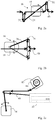
- Fig. 2a an alternative embodiment of a motor driven loop buffer device 16 is shown.
- the motor driven loop buffer device 16 in Fig. 2a comprises a double arm 24 having yarn guides 31, 32 provided at each end section of the double arm 24.
- the yarn guides 31, 32 are provided at each end of the double arm 24.
- a mid-section of the double arm 24 is attached to the motor 18.
- the mid-section can be attached directly to the shaft of the motor 18.
- a double arm 24 can be controlled with better dynamic properties compared to a single arm.
- a drawback of a double arm configuration is however that the total deflection angle of the weft yarn 40 is higher, about 720°.
- FIG. 2b Another alternative motor driven loop buffer device 16 is shown in Fig. 2b .
- the motor driven loop buffer device 16 in Fig. 2b comprises a two-way single arm 26.
- the two-way single arm 26 comprises a double weft yarn guide 34 that brings the weft yarn both ways, e.g. upwards and downwards, past a center line for the weft yarn 40.
- the center line constitutes a neutral position for the buffer formed by the motor driven loop buffer device 16.
- the weft yarn buffer formed by the motor driven loop buffer device 16 changes from yarn let-out to yarn take-up with low power input.
- the bobbin is placed so that the yarn going to the arm is first travelling in a direction away from the weaving machine resulting in a total deflection angle of much less than 360 degrees. It can be as low as approximately 180 degrees.
- the motor driven loop buffer is formed by a member driven back and forth along a path.
- the member can be driven back and forth along a path that is straight.
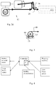
- FIG. 3 An alternative motor driven bobbin 13 is shown in Fig. 3 .
- the bobbin 13 is unrolled using a tangential drive where drive member(s) 15 of the motor 14 are located outside the bobbin 13.
- a tangential drive has the benefit that the rotational speed is linear to the unrolling speed and that the diameter of the bobbin is not influencing the unrolling speed of the yarn.
- a controller 32 can be used.
- the controller can be provided with control data to control the speed of the motor drive and the movement of the motor driven loop buffer device 16.
- the controller can be provided with control data to control the speed of the motor drive and the movement of the motor driven loop buffer device 16.
- weft yarn can be supplied to the weaving machine correctly at high weaving speed.
- Fig. 4 a representation of a control system as described above is shown.
- the controller of the control system can in accordance with one embodiment be programmed with the angle-position curve of the rapier movement. Before machine start the controller can be provided with information about the weaving machine speed, ramp up and starting position. During running the controller gets information about the machine position by e.g. the machine angle sensor (encoder).
- the machine angle sensor encoder
- the controller is programmed to run the bobbin un-wind motor at a speed at which the average amount of weft yarn that the weaving machine consumes is unwound from the bobbin or close to such a speed.
- the controller is programmed to run the motor of the loop-forming arm so that the movement of the arm compensates for the difference of the essentially constant un-wind speed of the weft yarn from the bobbin and the intermittent consumption of weft yarn by the weaving machine.
- the motor of a motor driven buffer device is driven to keep the buffered yarn length equal to, or within a pre-determined range around, the difference between the amount of yarn unrolled from the bobbin and the amount of yarn consumed by the weaving machine during the insertion to thereby control the yarn tension.
- the target of the control system can in accordance with one embodiment be to have a constant yarn tension or to follow a varying yarn tension curve over a weaving machine cycle.
- the speed of the motor of the motor driven bobbin is adjusted based on another input signal than a signal representing the actual yarn tension.
- a signal representing the position of the motor driven loop buffer device can be used or any other signal indicative of if the bobbin is unwound at a speed that matches the average yarn consumption of the weaving machine.
- a signal indicative of accumulated errors in the amount of yarn fed to the weaving machine can be used.
- errors compensated for by the yarn buffer can be restored and the yarn buffer be returned to a neutral position.
- a force sensor detecting the yarn tension can be used to give feedback to the control system in order to correct for the error between the expected consumption of the weaving machine and the real consumption, both in average and during the actual insertion.
- the control system can also be programmed to correct for the error between the expected amount of yarn unrolled from the bobbin and real amount based on a feedback signal from the force sensor.
- the control output signal can be rpm.
- it is unwound weft yarn length / time unit, e.g. m/s that is the parameter that is to be controlled.
- it is important to know the actual circumference of the bobbin. This is especially important at start-up of the system.
- a sensor that measures the diameter of the bobbin can for example be used, or a manual input at start up can be entered to the control system as one of the parameters P or some other method can be used.
- the motors of the weft yarn feeding arrangement can be controlled according to the following principles:
- the controller for control of the motor running the loop-forming arm has a preset value for the required buffer position in relation to the weaving machine angle.
- the controller is also provided with information about the dynamics of the system.
- When the weaving machine is running the motor driven loop-forming arm will be controlled to act accordingly in order to always have the buffer arm in the proper position at all weaving machine angles and weaving machine speeds.
- the force sensor gives a feedback to the control system so it can correct deviations, such as external influence and also dynamic model pre-set values or actual running inaccuracy.
- a one-sided rapier machine can be used. By this the problems with speed shift at transfer is avoided. Also, the start of the pick is much more gentle as the rapier has not reached a high speed before it takes the yarn.
- the additional buffer can comprise a mechanical element or a spring-loaded member.
- Fig. 2d a set-up with an additional yarn buffer 36.
- the additional yarn buffer 36 is here formed in conjunction with the sensor 29 such that the sensor 29 is somewhat resilient and allows for yarn length deviations. Because the speed change at transfer has a short duration the buffered amount of yarn is typically very small.
- the length of the additional buffer is less than 10% of the maximal buffer of the motor driven loop buffer device 16, such as maximally 1 or 2 dm. Also for a one-sided rapier a small additional mechanical or spring loaded buffer might be advantageous.
- the additional buffer can have a very short stroke, for example less than one or two cm. This enables the system to cope with small errors. These errors can for example result from the machine speed not being constant, the rapier takes and leaves the yarn with some length variation from pick to pick or the binding between weft and warp might vary slightly from pick to pick etc.
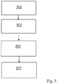
- a flow chart illustrating some steps when controlling a weft yarn feeding arrangement 12 feeding yarn 40 to a rapier weaving machine 10 is shown.
- the controller is provided with information relating to speed of the rapier(s) at different points in time during running of the rapier weaving machine.
- a model of weft yarn insertion speed in the weaving machine during a machine cycle is formed.
- the actions in step 501 can be taken before start-up of the system and are not necessarily part of the control procedure.
- a look-up table of relevant control data can be pre-loaded to a controller.
- the motor driven bobbin is controlled to supply weft yarn at an, essentially constant, speed such that the amount of weft yarn unrolled meets the amount of weft yarn consumed by the rapier weaving machine.
- the motor of the motor driven loop buffer device is driven based on the difference between the output speed of yarn from the motor driven bobbin and the model of weft yarn insertion speed in the weaving machine.
- the drive the motor of the motor driven loop buffer device is adjusted based on a signal representing the actual weft yarn tension. Also, the speed of the motor of the motor driven bobbin can be adjusted based on a signal representing the actual weft yarn tension.
- a controller 32 for controlling a weft yarn feeding arrangement 12 is depicted.
- the controller 32 can comprise an input/output 81 for receiving input signals for parameters used for controlling the yarn feeding device as set out above.
- the input signals can be various sensor signals from sensors of the yarn feeding device.
- sensor signals can be provided from any type of sensor, e.g. optical sensors, mechanical sensors or capacitive sensors.
- the yarn tension sensor(s) can for example be a piezo resistive type sensor, a strain gauge type sensor, or by sensing the position of a resilient or spring loaded yarn guide.
- the yarn length can be determined.
- the yarn length can be used as an alternative or in combination with a yarn tension signal as a feed-back signal to control the motor speed of the motor driven loop buffer device and in some embodiments as a feedback signal to control the motor speed of the motor driven bobbin.
- Other types of input signals can also be provided such as encoder signals and the like.
- signals from the rapier weaving machine can be input to the controller 32 and used to control the weft yarn feeding arrangement. In particular, the weaving machine angle can be provided.
- the input/output 81 outputs motor control signal(s) to the controlled motors of the weft yarn feeding arrangement.
- the controller 32 further comprises a micro-processor that also can be referred to as a processing unit 82.
- the processing unit 82 is connected to and can execute computer program instructions stored in a memory 83.
- the memory 83 can also store data that can be accessed by the processing unit 82.
- the data in the memory can comprise pre-stored data relating to the weaving machine 10.
- a model of the rapier movements can be stored to form a model of the weft yarn speed into the rapier weaving machine.
- the computer program instructions can be adapted to cause the controller to control the yarn feeding arrangement in accordance with the teachings herein.
- the controller 32 can be located at any suitable location.
- the controller 32 can be integrated in a motor of the yarn feeding arrangement.
- the controller 32 can also be distributed at different locations.
- a light weight moving arm or other yarn loop forming member can be used. It can be of several types, for example using light and stiff materials like carbon fiber, or a light weight design in aluminum sheet.
- the yarn feeding arrangement as described herein is a so called positive feed system; it measures and outputs a pre-defined amount of yarn in synchronism with the weaving machine angle.
- the yarn feeding arrangement controls the amount of yarn available for the weaving machine in that the weaving machine cannot draw more yarn than the yarn feeding arrangement has fed.
- This in contrast to a so called negative feeding arrangement where the weaving machine draws an amount of yarn without being limited by how much yarn the yarn feeder can supply.
- the weaving machine has more or less free access to yarn
- the yarn feed arrangement determines how much yarn can be fed to the weaving machine.
- the feedback to correct errors between the pre-defined amount of yarn and the real consumption in the positive feed system is obtained by a sensor, in particular a yarn tension sensor.
- the yarn tension sensor is combined with a small mechanical or spring loaded yarn buffer.
Landscapes
- Engineering & Computer Science (AREA)
- Textile Engineering (AREA)
- Looms (AREA)
Claims (15)
- Fadenzuführanordnung (12), die sich zum Zuführen eines Schussfadens (40) zu einer Webmaschine (10) eignet, die mindestens einen Greifer (11) aufweist, wobei der zur Webmaschine zugeführte Schussfaden eine gesteuerte Fadenspannung aufweist, wobei die Fadenzuführanordnung eine motorgetriebene Spule (13) und eine motorgetriebene Schleifenpuffervorrichtung (16) umfasst, wobei die Fadenzuführanordnung weiter eine Steuerung (32) zum Steuern des Motors der motorgetriebenen Spule und der motorgetriebenen Schleifenpuffervorrichtung umfasst, wobei die Steuerung angepasst ist, um- den Motor (14) der motorgetriebenen Spule mit einer Geschwindigkeit anzutreiben, um eine bestimmte im Wesentlichen Durchschnittsmenge eines durch die Webmaschine zu verbrauchenden Schussfadens zuzuführen, wobei die bestimmte im Wesentlichen Durchschnittsmenge eines Schussfadens um weniger als eine voreingestellte Menge von der tatsächlichen, von Webmaschine verbrauchten Durchschnittsmenge abweicht;- den Motor der motorgetriebenen Schleifenpuffervorrichtung basierend auf der Differenz zwischen der Ausgangsgeschwindigkeit eines Fadens (40) von der motorgetriebenen Spule und einem Modell einer Schussfadeneinführungsgeschwindigkeit in die Webmaschine anzutreiben, und- den Antrieb des Motors der motorgetriebenen Schleifenpuffervorrichtung basierend auf einem Signal anzupassen, das die tatsächliche Schussfadenspannung repräsentiert oder einem Signal, das die Länge des tatsächlich in die Webmaschine eingeführten Schussfadens repräsentiert.
- Fadenzuführanordnung (12) nach Anspruch 1, wobei die motorgetriebene Schleifenpuffervorrichtung durch einen Arm (22, 24, 26) gebildet wird, der mit dem Motor der motorgetriebenen Schleifenpuffervorrichtung verbunden ist.
- Fadenzuführanordnung (12) nach Anspruch 2, wobei die motorgetriebene Schleifenpuffervorrichtung durch einen Arm (22, 24, 26) gebildet wird, der direkt an einer Ausgangswelle des Motors der motorgetriebenen Schleifenpuffervorrichtung (16) befestigt, oder über eine Getriebeanordnung mit der Ausgangswelle verbunden ist.
- Fadenzuführanordnung (12) nach Anspruch 1, wobei die motorgetriebene Schleifenpuffervorrichtung durch ein sich rückwärts und vorwärts bewegendes Element gebildet wird.
- Fadenzuführanordnung (12) nach Anspruch 1 bis 4, wobei das Modell einer Schussfadeneinführungsgeschwindigkeit auf Parametern basiert, die Informationen über die Greiferposition oder Geschwindigkeit in Bezug auf eine Maschinenwinkelposition der Webmaschine und Informationen über die Länge des Hakens umfassen.
- Fadenzuführanordnung (12) nach Anspruch 1 bis 5, wobei die Steuerung (32) angepasst ist, um Informationen über eine momentane Maschinenwinkelposition der Webmaschine zu empfangen, welche von der Webmaschine zu der Fadenzuführanordnung übertragen werden.
- Fadenzuführanordnung (12) nach Anspruch 1 bis 6, wobei die Steuerung (32) angepasst ist, um Informationen über die Schussvorlage zu empfangen, die vor dem Start und/ oder währed des Laufens der Webmaschine an die Fadenzuführanordnung übertragen werden.
- Fadenzuführanordnung (12) nach Anspruch 1 bis 7, wobei die Steuerung angepasst ist, um den Motor der motorgetriebenen Schleifenpuffervorrichtung basierend auf Informationen über die Geometrie der Schleifenpuffervorrichtung und/ oder auf Informationen über die Dynamik von mindestens einem beweglichen Teil der motorgetriebenen Schleifenpuffervorrichtung anzutreiben.
- Fadenzuführanordnung (12) nach einem der Ansprüche 1 bis 8, wobei die Geschwindigkeit des Motors (14) der motorgetriebenen Spule basierend auf einem Signal angepasst wird, das die tatsächliche Schussfadenspannung repräsentiert.
- Fadenzuführanordnung (12) nach einem der Ansprüche 1 bis 9, wobei die Geschwindigkeit eines Motors (14) der motorgetriebenen Spule basierend auf einem Signal angepasst wird, das die Position der motorgetriebenen Schleifenpuffervorrichtung repräsentiert.
- Fadenzuführanordnung (12) nach einem der Ansprüche 1 bis 10, wobei die Steuerung angepasst ist, um, wenn eine Differenz zwischen der tatsächlichen Durchschnittsmenge eines von der Spule zugeführten Fadens und der tatsächlichen von der Webmaschine verbrauchten Durchschnittsmenge detektiert wird, die Geschwindigkeit des Motors (14) der motorgetriebenen Spule zu steuern, um die Differenz auszugleichen.
- Fadenzuführanordnung (12) nach einem der Ansprüche 1 bis 11, wobei die Steuerung (32) angepasst ist, um den Motor (14) der motorgetriebenen Schleifenpuffervorrichtung (16) zu steuern, um während des Einführens die gepufferte Fadenlänge gleich oder innerhalb eines vorbestimmten Bereichs um die Differenz zwischen der Menge an von der Spule abgerolltem Faden und der Menge von durch die Webmaschine verbrauchten Faden zu halten, wodurch die Fadenspannung gesteuert wird.
- Fadenzuführanordnung (12) nach Anspruch 12, wobei die Steuerung (32) angepasst ist, um den Motor (14) der motorgetriebenen Schleifenpuffervorrichtung (16) zu steuern, um die gesteuerte Fadenspannung konstant zu halten, oder um die gesteuerte Fadenspannung einer vorbestimmten Fadenspannungskurve über einen Webmaschinenzyklus folgen zu lassen.
- Verfahren zur Steuerung einer Fadenzuführanordnung (12) zum Zuführen eines Schussfadens (40) zu einer Webmaschine (10), die mindestens einen Greifer (11) aufweist, wobei der zur Webmaschine zugeführte Schussfaden eine gesteuerte Fadenspannung aufweist, wobei die Fadenzuführanordnung eine motorgetriebene Spule (13) und eine motorgetriebene Schleifenpuffervorrichtung (16) umfasst, wobei die Fadenzuführanordnung weiter eine Steuerung (32) zum Steuern des Motors der motorgetriebenen Spule und der motorgetriebenen Schleifenpuffervorrichtung umfasst, wobei das Verfahren umfasst- Antreiben (503) des Motors (14) der motorgetriebenen Spule mit einer Geschwindigkeit, um eine bestimmte im Wesentlichen Durchschnittsmenge eines durch die Webmaschine zu verbrauchenden Schussfadens zuzuführen, wobei die bestimmte im Wesentlichen Durchschnittsmenge eines Schussfadens um weniger als eine voreingestellte Menge von der tatsächlichen, von Webmaschine verbrauchten Durchschnittsmenge abweicht;- Antreiben (505) des Motors der motorgetriebenen Schleifenpuffervorrichtung basierend auf der Differenz zwischen der Ausgangsgeschwindigkeit eines Fadens (40) von der motorgetriebenen Spule und einem Modell einer Schussfadeneinführungsgeschwindigkeit in die Webmaschine, und- Anpassen (507) des Antriebs des Motors der motorgetriebenen Schleifenpuffervorrichtung basierend auf einem Signal, das die tatsächliche Schussfadenspannung repräsentiert oder einem Signal, das die Länge des tatsächlich in die Webmaschine eingeführten Schussfadens repräsentiert.
- Computerprogrammprodukt, umfassend einen Computerprogrammcode, der angepasst ist, um, wenn er auf einem Computer ausgeführt wird, zu bewirken, dass der Computer die Fadenzuführanordnung (12) nach Anspruch 1 steuert, um die Schritte des Verfahrens nach Anspruch 14 auszuführen.
Applications Claiming Priority (2)
| Application Number | Priority Date | Filing Date | Title |
|---|---|---|---|
| SE1651028 | 2016-07-11 | ||
| PCT/SE2017/050671 WO2018013033A1 (en) | 2016-07-11 | 2017-06-20 | Zero-twist yarn feeding device |
Publications (3)
| Publication Number | Publication Date |
|---|---|
| EP3481981A1 EP3481981A1 (de) | 2019-05-15 |
| EP3481981A4 EP3481981A4 (de) | 2020-03-04 |
| EP3481981B1 true EP3481981B1 (de) | 2021-02-24 |
Family
ID=60952159
Family Applications (1)
| Application Number | Title | Priority Date | Filing Date |
|---|---|---|---|
| EP17828057.4A Active EP3481981B1 (de) | 2016-07-11 | 2017-06-20 | Verdrehungsfreie fadenzuführvorrichtung |
Country Status (4)
| Country | Link |
|---|---|
| EP (1) | EP3481981B1 (de) |
| JP (1) | JP6953452B2 (de) |
| CN (1) | CN109415852B (de) |
| WO (1) | WO2018013033A1 (de) |
Families Citing this family (5)
| Publication number | Priority date | Publication date | Assignee | Title |
|---|---|---|---|---|
| CN112955592B (zh) * | 2018-10-18 | 2023-03-07 | 范德威尔瑞典公司 | 具有学习程序的纱线进给设备 |
| EP3867432A1 (de) * | 2018-10-18 | 2021-08-25 | Vandewiele Sweden AB | Spulenantriebseinheit, fadenzuführvorrichtung und halter zum halten einer spule |
| CN113011854B (zh) * | 2021-03-29 | 2024-09-20 | 广东溢达纺织有限公司 | 经纱与纬纱匹配结果的确定方法、装置和计算机设备 |
| JP7603534B2 (ja) * | 2021-06-10 | 2024-12-20 | 本田技研工業株式会社 | フィラメントワインディング方法及びフィラメントワインディング装置 |
| CN115258823B (zh) * | 2022-05-19 | 2023-08-22 | 西安航空学院 | 一种光纤绕线机张力调节结构及方法 |
Family Cites Families (17)
| Publication number | Priority date | Publication date | Assignee | Title |
|---|---|---|---|---|
| CH471261A (de) * | 1968-03-21 | 1969-04-15 | Sulzer Ag | Einrichtung zum Speichern des Schussmaterials bei Webmaschinen |
| CH542130A (de) * | 1971-09-02 | 1973-09-30 | Sulzer Ag | Einrichtung zum Speichern von band- oder fadenförmigem Material für Textilmaschinen, insbesondere Webmaschinen |
| CH556929A (de) * | 1972-10-09 | 1974-12-13 | Sulzer Ag | Webmaschine. |
| US5150739A (en) * | 1991-07-11 | 1992-09-29 | E. I. Du Pont De Nemours And Company | Weft feeding through an accumulator without substantial twist |
| EP0672204B1 (de) * | 1992-12-03 | 1998-04-15 | Iro Ab | Verfahren zum steuern eines fadenliefersystems und fadenliefersystem |
| JPH11222749A (ja) * | 1998-02-02 | 1999-08-17 | Sakai Composite Kk | 扁平糸織物の製造方法及び製造装置 |
| DE19942121A1 (de) * | 1999-09-03 | 2001-03-08 | Iro Patent Ag Baar | Verfahren zum Steuern eines Fadenverarbeitungssystems und Fadenverarbeitungssystem |
| SE0100509L (sv) * | 2001-02-16 | 2002-02-05 | Texo Ab | Förfarande och anordning för att längdmäta och magasinera tråd vid väv- eller textilmaskiner |
| FR2864555B1 (fr) * | 2003-12-24 | 2006-01-27 | Staubli Lyon | Procede de controle de la tension d'alimentation d'au moins un fil de trame, dispositif d'alimentation en fil de trame et metier a tisser equipe d'un tel dispositif |
| JP2007126784A (ja) * | 2005-11-04 | 2007-05-24 | Avr:Kk | 織機用テープ状横糸送り出し装置 |
| EP2031106B1 (de) * | 2007-08-31 | 2010-02-24 | L.G.L. Electronics S.p.A. | Verfahren zur Spannungskontrolle eines Garnes, das von einem negativen Liefergerät an eine Textilmaschine geliefert wird, und Vorrichtung zur Durchführung des Verfahrens |
| EP2128318A1 (de) * | 2008-05-30 | 2009-12-02 | Iro Ab | Aufnahmevorrichtung |
| JP5163301B2 (ja) * | 2008-06-10 | 2013-03-13 | 株式会社豊田自動織機 | 流体噴射式織機における緯糸引戻し装置の操作方法 |
| IT1395552B1 (it) * | 2009-09-01 | 2012-09-28 | Ergotron Dondi Benelli Dore | Dispositivo per lo svolgimento controllato di un elemento a nastro o piattina avvolto su una rocca, in particolare una trama piatta per tessitura |
| KR20110119426A (ko) * | 2010-04-27 | 2011-11-02 | 한국섬유개발연구원 | 플랫얀용 위사공급장치 |
| DE102012212169A1 (de) * | 2012-07-11 | 2014-01-16 | Lindauer Dornier Gesellschaft Mit Beschränkter Haftung | Vorrichtung zum Zwischenspeichern von bandartigem Schussmaterial für eine Webmaschine und Webmaschine mit einer solchen Vorrichtung |
| CN205088395U (zh) * | 2015-10-21 | 2016-03-16 | 嵊州市中森电子有限公司 | 一种应用于喷水织机的储纬器 |
-
2017
- 2017-06-20 JP JP2018564932A patent/JP6953452B2/ja active Active
- 2017-06-20 CN CN201780041959.1A patent/CN109415852B/zh active Active
- 2017-06-20 WO PCT/SE2017/050671 patent/WO2018013033A1/en not_active Ceased
- 2017-06-20 EP EP17828057.4A patent/EP3481981B1/de active Active
Non-Patent Citations (1)
| Title |
|---|
| None * |
Also Published As
| Publication number | Publication date |
|---|---|
| CN109415852B (zh) | 2020-09-18 |
| WO2018013033A1 (en) | 2018-01-18 |
| JP6953452B2 (ja) | 2021-10-27 |
| JP2019525013A (ja) | 2019-09-05 |
| EP3481981A1 (de) | 2019-05-15 |
| EP3481981A4 (de) | 2020-03-04 |
| CN109415852A (zh) | 2019-03-01 |
Similar Documents
| Publication | Publication Date | Title |
|---|---|---|
| EP3481981B1 (de) | Verdrehungsfreie fadenzuführvorrichtung | |
| EP1991726B1 (de) | Verbesserte vorrichtung zur beschickung einer textilmaschine mit einem faden oder garn sowie beschickungsverfahren | |
| CN101768827B (zh) | 设有张力限制装置的积极式纱线馈送器 | |
| JP5759179B2 (ja) | 非連続状態で供給される糸又は糸状体を一定張力で供給する装置及び方法 | |
| EP2868609B1 (de) | Garnbereitstellungssystem | |
| EP3867431B1 (de) | Fadenzuführvorrichtung mit lernverfahren | |
| JP5805079B2 (ja) | 糸供給システム | |
| EP3481979B1 (de) | Einen zwischengarnpuffer formende schussfadenzuführvorrichtung und verfahren zur steuerung einer schussfadenzuführvorrichtung | |
| CN111699144B (zh) | 用于将纱线进给至加工机器的方法、系统及补偿器设备 | |
| CN113924391A (zh) | 对经纱中的纱线张力进行控制或调节的织造方法及使用该织造方法生产织物的织机 | |
| KR101156593B1 (ko) | 적어도 하나의 위사의 공급 장력을 조절하는 방법, 위사공급 장치 및 그러한 장치가 장착된 직기 | |
| US20050061388A1 (en) | Yarn processing system | |
| JP2010228852A (ja) | 糸継機構及びそれを用いたサンプル整経機 | |
| JP2008002032A (ja) | 織機用のよこ糸供給方法 | |
| EP2128318A1 (de) | Aufnahmevorrichtung | |
| CN1208510C (zh) | 用于插入弹性体纱的方法和纱线处理系统 | |
| WO2024128950A1 (en) | Yarn feeder especially for heavy yarns | |
| JP2007126784A (ja) | 織機用テープ状横糸送り出し装置 | |
| EP3374303B1 (de) | Gesteuertes system zum zuführen von schussgarn in einer webmaschine | |
| ES3005087T3 (en) | Method for controlled winding of a textile product on a textile machine, and textile machine | |
| EP3481980B1 (de) | Schussfadenzuführvorrichtung mit endlos laufendem band und verfahren zum steuern der anordnung | |
| JPH0616945Y2 (ja) | 三次元織機の経糸供給装置 | |
| KR101131457B1 (ko) | 직기용 편평상 위사송출장치 | |
| JP2001234450A (ja) | 流体噴射式織機の緯入れ方法とその装置 |
Legal Events
| Date | Code | Title | Description |
|---|---|---|---|
| STAA | Information on the status of an ep patent application or granted ep patent |
Free format text: STATUS: THE INTERNATIONAL PUBLICATION HAS BEEN MADE |
|
| PUAI | Public reference made under article 153(3) epc to a published international application that has entered the european phase |
Free format text: ORIGINAL CODE: 0009012 |
|
| STAA | Information on the status of an ep patent application or granted ep patent |
Free format text: STATUS: REQUEST FOR EXAMINATION WAS MADE |
|
| 17P | Request for examination filed |
Effective date: 20181130 |
|
| AK | Designated contracting states |
Kind code of ref document: A1 Designated state(s): AL AT BE BG CH CY CZ DE DK EE ES FI FR GB GR HR HU IE IS IT LI LT LU LV MC MK MT NL NO PL PT RO RS SE SI SK SM TR |
|
| AX | Request for extension of the european patent |
Extension state: BA ME |
|
| DAV | Request for validation of the european patent (deleted) | ||
| DAX | Request for extension of the european patent (deleted) | ||
| A4 | Supplementary search report drawn up and despatched |
Effective date: 20200130 |
|
| RIC1 | Information provided on ipc code assigned before grant |
Ipc: D03D 47/36 20060101ALI20200124BHEP Ipc: B65H 59/34 20060101ALI20200124BHEP Ipc: D03D 47/34 20060101AFI20200124BHEP |
|
| GRAP | Despatch of communication of intention to grant a patent |
Free format text: ORIGINAL CODE: EPIDOSNIGR1 |
|
| STAA | Information on the status of an ep patent application or granted ep patent |
Free format text: STATUS: GRANT OF PATENT IS INTENDED |
|
| INTG | Intention to grant announced |
Effective date: 20201102 |
|
| GRAS | Grant fee paid |
Free format text: ORIGINAL CODE: EPIDOSNIGR3 |
|
| GRAA | (expected) grant |
Free format text: ORIGINAL CODE: 0009210 |
|
| STAA | Information on the status of an ep patent application or granted ep patent |
Free format text: STATUS: THE PATENT HAS BEEN GRANTED |
|
| RAP1 | Party data changed (applicant data changed or rights of an application transferred) |
Owner name: VANDEWIELE SWEDEN AB |
|
| AK | Designated contracting states |
Kind code of ref document: B1 Designated state(s): AL AT BE BG CH CY CZ DE DK EE ES FI FR GB GR HR HU IE IS IT LI LT LU LV MC MK MT NL NO PL PT RO RS SE SI SK SM TR |
|
| REG | Reference to a national code |
Ref country code: CH Ref legal event code: EP |
|
| REG | Reference to a national code |
Ref country code: DE Ref legal event code: R096 Ref document number: 602017033490 Country of ref document: DE |
|
| REG | Reference to a national code |
Ref country code: AT Ref legal event code: REF Ref document number: 1364554 Country of ref document: AT Kind code of ref document: T Effective date: 20210315 |
|
| REG | Reference to a national code |
Ref country code: IE Ref legal event code: FG4D |
|
| REG | Reference to a national code |
Ref country code: LT Ref legal event code: MG9D |
|
| REG | Reference to a national code |
Ref country code: NL Ref legal event code: MP Effective date: 20210224 |
|
| PG25 | Lapsed in a contracting state [announced via postgrant information from national office to epo] |
Ref country code: LT Free format text: LAPSE BECAUSE OF FAILURE TO SUBMIT A TRANSLATION OF THE DESCRIPTION OR TO PAY THE FEE WITHIN THE PRESCRIBED TIME-LIMIT Effective date: 20210224 Ref country code: BG Free format text: LAPSE BECAUSE OF FAILURE TO SUBMIT A TRANSLATION OF THE DESCRIPTION OR TO PAY THE FEE WITHIN THE PRESCRIBED TIME-LIMIT Effective date: 20210524 Ref country code: NO Free format text: LAPSE BECAUSE OF FAILURE TO SUBMIT A TRANSLATION OF THE DESCRIPTION OR TO PAY THE FEE WITHIN THE PRESCRIBED TIME-LIMIT Effective date: 20210524 Ref country code: PT Free format text: LAPSE BECAUSE OF FAILURE TO SUBMIT A TRANSLATION OF THE DESCRIPTION OR TO PAY THE FEE WITHIN THE PRESCRIBED TIME-LIMIT Effective date: 20210624 Ref country code: GR Free format text: LAPSE BECAUSE OF FAILURE TO SUBMIT A TRANSLATION OF THE DESCRIPTION OR TO PAY THE FEE WITHIN THE PRESCRIBED TIME-LIMIT Effective date: 20210525 Ref country code: HR Free format text: LAPSE BECAUSE OF FAILURE TO SUBMIT A TRANSLATION OF THE DESCRIPTION OR TO PAY THE FEE WITHIN THE PRESCRIBED TIME-LIMIT Effective date: 20210224 Ref country code: FI Free format text: LAPSE BECAUSE OF FAILURE TO SUBMIT A TRANSLATION OF THE DESCRIPTION OR TO PAY THE FEE WITHIN THE PRESCRIBED TIME-LIMIT Effective date: 20210224 |
|
| REG | Reference to a national code |
Ref country code: AT Ref legal event code: MK05 Ref document number: 1364554 Country of ref document: AT Kind code of ref document: T Effective date: 20210224 |
|
| PG25 | Lapsed in a contracting state [announced via postgrant information from national office to epo] |
Ref country code: NL Free format text: LAPSE BECAUSE OF FAILURE TO SUBMIT A TRANSLATION OF THE DESCRIPTION OR TO PAY THE FEE WITHIN THE PRESCRIBED TIME-LIMIT Effective date: 20210224 Ref country code: LV Free format text: LAPSE BECAUSE OF FAILURE TO SUBMIT A TRANSLATION OF THE DESCRIPTION OR TO PAY THE FEE WITHIN THE PRESCRIBED TIME-LIMIT Effective date: 20210224 Ref country code: RS Free format text: LAPSE BECAUSE OF FAILURE TO SUBMIT A TRANSLATION OF THE DESCRIPTION OR TO PAY THE FEE WITHIN THE PRESCRIBED TIME-LIMIT Effective date: 20210224 Ref country code: PL Free format text: LAPSE BECAUSE OF FAILURE TO SUBMIT A TRANSLATION OF THE DESCRIPTION OR TO PAY THE FEE WITHIN THE PRESCRIBED TIME-LIMIT Effective date: 20210224 Ref country code: SE Free format text: LAPSE BECAUSE OF FAILURE TO SUBMIT A TRANSLATION OF THE DESCRIPTION OR TO PAY THE FEE WITHIN THE PRESCRIBED TIME-LIMIT Effective date: 20210224 |
|
| PG25 | Lapsed in a contracting state [announced via postgrant information from national office to epo] |
Ref country code: IS Free format text: LAPSE BECAUSE OF FAILURE TO SUBMIT A TRANSLATION OF THE DESCRIPTION OR TO PAY THE FEE WITHIN THE PRESCRIBED TIME-LIMIT Effective date: 20210624 |
|
| PG25 | Lapsed in a contracting state [announced via postgrant information from national office to epo] |
Ref country code: SM Free format text: LAPSE BECAUSE OF FAILURE TO SUBMIT A TRANSLATION OF THE DESCRIPTION OR TO PAY THE FEE WITHIN THE PRESCRIBED TIME-LIMIT Effective date: 20210224 Ref country code: AT Free format text: LAPSE BECAUSE OF FAILURE TO SUBMIT A TRANSLATION OF THE DESCRIPTION OR TO PAY THE FEE WITHIN THE PRESCRIBED TIME-LIMIT Effective date: 20210224 Ref country code: EE Free format text: LAPSE BECAUSE OF FAILURE TO SUBMIT A TRANSLATION OF THE DESCRIPTION OR TO PAY THE FEE WITHIN THE PRESCRIBED TIME-LIMIT Effective date: 20210224 Ref country code: CZ Free format text: LAPSE BECAUSE OF FAILURE TO SUBMIT A TRANSLATION OF THE DESCRIPTION OR TO PAY THE FEE WITHIN THE PRESCRIBED TIME-LIMIT Effective date: 20210224 |
|
| REG | Reference to a national code |
Ref country code: DE Ref legal event code: R097 Ref document number: 602017033490 Country of ref document: DE |
|
| PG25 | Lapsed in a contracting state [announced via postgrant information from national office to epo] |
Ref country code: SK Free format text: LAPSE BECAUSE OF FAILURE TO SUBMIT A TRANSLATION OF THE DESCRIPTION OR TO PAY THE FEE WITHIN THE PRESCRIBED TIME-LIMIT Effective date: 20210224 Ref country code: DK Free format text: LAPSE BECAUSE OF FAILURE TO SUBMIT A TRANSLATION OF THE DESCRIPTION OR TO PAY THE FEE WITHIN THE PRESCRIBED TIME-LIMIT Effective date: 20210224 Ref country code: RO Free format text: LAPSE BECAUSE OF FAILURE TO SUBMIT A TRANSLATION OF THE DESCRIPTION OR TO PAY THE FEE WITHIN THE PRESCRIBED TIME-LIMIT Effective date: 20210224 |
|
| PLBE | No opposition filed within time limit |
Free format text: ORIGINAL CODE: 0009261 |
|
| STAA | Information on the status of an ep patent application or granted ep patent |
Free format text: STATUS: NO OPPOSITION FILED WITHIN TIME LIMIT |
|
| PG25 | Lapsed in a contracting state [announced via postgrant information from national office to epo] |
Ref country code: ES Free format text: LAPSE BECAUSE OF FAILURE TO SUBMIT A TRANSLATION OF THE DESCRIPTION OR TO PAY THE FEE WITHIN THE PRESCRIBED TIME-LIMIT Effective date: 20210224 Ref country code: MC Free format text: LAPSE BECAUSE OF FAILURE TO SUBMIT A TRANSLATION OF THE DESCRIPTION OR TO PAY THE FEE WITHIN THE PRESCRIBED TIME-LIMIT Effective date: 20210224 Ref country code: AL Free format text: LAPSE BECAUSE OF FAILURE TO SUBMIT A TRANSLATION OF THE DESCRIPTION OR TO PAY THE FEE WITHIN THE PRESCRIBED TIME-LIMIT Effective date: 20210224 |
|
| REG | Reference to a national code |
Ref country code: CH Ref legal event code: PL |
|
| 26N | No opposition filed |
Effective date: 20211125 |
|
| GBPC | Gb: european patent ceased through non-payment of renewal fee |
Effective date: 20210620 |
|
| PG25 | Lapsed in a contracting state [announced via postgrant information from national office to epo] |
Ref country code: SI Free format text: LAPSE BECAUSE OF FAILURE TO SUBMIT A TRANSLATION OF THE DESCRIPTION OR TO PAY THE FEE WITHIN THE PRESCRIBED TIME-LIMIT Effective date: 20210224 |
|
| REG | Reference to a national code |
Ref country code: BE Ref legal event code: MM Effective date: 20210630 |
|
| PG25 | Lapsed in a contracting state [announced via postgrant information from national office to epo] |
Ref country code: LU Free format text: LAPSE BECAUSE OF NON-PAYMENT OF DUE FEES Effective date: 20210620 |
|
| PG25 | Lapsed in a contracting state [announced via postgrant information from national office to epo] |
Ref country code: LI Free format text: LAPSE BECAUSE OF NON-PAYMENT OF DUE FEES Effective date: 20210630 Ref country code: IE Free format text: LAPSE BECAUSE OF NON-PAYMENT OF DUE FEES Effective date: 20210620 Ref country code: GB Free format text: LAPSE BECAUSE OF NON-PAYMENT OF DUE FEES Effective date: 20210620 Ref country code: CH Free format text: LAPSE BECAUSE OF NON-PAYMENT OF DUE FEES Effective date: 20210630 |
|
| PG25 | Lapsed in a contracting state [announced via postgrant information from national office to epo] |
Ref country code: IS Free format text: LAPSE BECAUSE OF FAILURE TO SUBMIT A TRANSLATION OF THE DESCRIPTION OR TO PAY THE FEE WITHIN THE PRESCRIBED TIME-LIMIT Effective date: 20210624 |
|
| PG25 | Lapsed in a contracting state [announced via postgrant information from national office to epo] |
Ref country code: BE Free format text: LAPSE BECAUSE OF NON-PAYMENT OF DUE FEES Effective date: 20210630 |
|
| PG25 | Lapsed in a contracting state [announced via postgrant information from national office to epo] |
Ref country code: CY Free format text: LAPSE BECAUSE OF FAILURE TO SUBMIT A TRANSLATION OF THE DESCRIPTION OR TO PAY THE FEE WITHIN THE PRESCRIBED TIME-LIMIT Effective date: 20210224 |
|
| PG25 | Lapsed in a contracting state [announced via postgrant information from national office to epo] |
Ref country code: HU Free format text: LAPSE BECAUSE OF FAILURE TO SUBMIT A TRANSLATION OF THE DESCRIPTION OR TO PAY THE FEE WITHIN THE PRESCRIBED TIME-LIMIT; INVALID AB INITIO Effective date: 20170620 |
|
| PG25 | Lapsed in a contracting state [announced via postgrant information from national office to epo] |
Ref country code: MK Free format text: LAPSE BECAUSE OF FAILURE TO SUBMIT A TRANSLATION OF THE DESCRIPTION OR TO PAY THE FEE WITHIN THE PRESCRIBED TIME-LIMIT Effective date: 20210224 |
|
| PG25 | Lapsed in a contracting state [announced via postgrant information from national office to epo] |
Ref country code: MT Free format text: LAPSE BECAUSE OF FAILURE TO SUBMIT A TRANSLATION OF THE DESCRIPTION OR TO PAY THE FEE WITHIN THE PRESCRIBED TIME-LIMIT Effective date: 20210224 |
|
| PGFP | Annual fee paid to national office [announced via postgrant information from national office to epo] |
Ref country code: DE Payment date: 20250618 Year of fee payment: 9 |
|
| PGFP | Annual fee paid to national office [announced via postgrant information from national office to epo] |
Ref country code: FR Payment date: 20250626 Year of fee payment: 9 |
|
| PGFP | Annual fee paid to national office [announced via postgrant information from national office to epo] |
Ref country code: TR Payment date: 20250617 Year of fee payment: 9 |
|
| PGFP | Annual fee paid to national office [announced via postgrant information from national office to epo] |
Ref country code: IT Payment date: 20250630 Year of fee payment: 9 |