EP3480679B1 - Regulierung der aktivität eines kerns - Google Patents
Regulierung der aktivität eines kerns Download PDFInfo
- Publication number
- EP3480679B1 EP3480679B1 EP18214036.8A EP18214036A EP3480679B1 EP 3480679 B1 EP3480679 B1 EP 3480679B1 EP 18214036 A EP18214036 A EP 18214036A EP 3480679 B1 EP3480679 B1 EP 3480679B1
- Authority
- EP
- European Patent Office
- Prior art keywords
- core
- clock
- cycles
- ratio
- value
- Prior art date
- Legal status (The legal status is an assumption and is not a legal conclusion. Google has not performed a legal analysis and makes no representation as to the accuracy of the status listed.)
- Active
Links
Images

Classifications
-
- G—PHYSICS
- G06—COMPUTING OR CALCULATING; COUNTING
- G06F—ELECTRIC DIGITAL DATA PROCESSING
- G06F1/00—Details not covered by groups G06F3/00 - G06F13/00 and G06F21/00
- G06F1/26—Power supply means, e.g. regulation thereof
- G06F1/32—Means for saving power
- G06F1/3203—Power management, i.e. event-based initiation of a power-saving mode
- G06F1/3206—Monitoring of events, devices or parameters that trigger a change in power modality
-
- G—PHYSICS
- G06—COMPUTING OR CALCULATING; COUNTING
- G06F—ELECTRIC DIGITAL DATA PROCESSING
- G06F1/00—Details not covered by groups G06F3/00 - G06F13/00 and G06F21/00
- G06F1/16—Constructional details or arrangements
- G06F1/20—Cooling means
- G06F1/206—Cooling means comprising thermal management
-
- G—PHYSICS
- G06—COMPUTING OR CALCULATING; COUNTING
- G06F—ELECTRIC DIGITAL DATA PROCESSING
- G06F1/00—Details not covered by groups G06F3/00 - G06F13/00 and G06F21/00
- G06F1/26—Power supply means, e.g. regulation thereof
- G06F1/32—Means for saving power
- G06F1/3203—Power management, i.e. event-based initiation of a power-saving mode
- G06F1/3234—Power saving characterised by the action undertaken
- G06F1/324—Power saving characterised by the action undertaken by lowering clock frequency
-
- G—PHYSICS
- G06—COMPUTING OR CALCULATING; COUNTING
- G06F—ELECTRIC DIGITAL DATA PROCESSING
- G06F1/00—Details not covered by groups G06F3/00 - G06F13/00 and G06F21/00
- G06F1/26—Power supply means, e.g. regulation thereof
- G06F1/32—Means for saving power
- G06F1/3203—Power management, i.e. event-based initiation of a power-saving mode
- G06F1/3234—Power saving characterised by the action undertaken
- G06F1/3296—Power saving characterised by the action undertaken by lowering the supply or operating voltage
-
- G—PHYSICS
- G06—COMPUTING OR CALCULATING; COUNTING
- G06F—ELECTRIC DIGITAL DATA PROCESSING
- G06F11/00—Error detection; Error correction; Monitoring
-
- Y—GENERAL TAGGING OF NEW TECHNOLOGICAL DEVELOPMENTS; GENERAL TAGGING OF CROSS-SECTIONAL TECHNOLOGIES SPANNING OVER SEVERAL SECTIONS OF THE IPC; TECHNICAL SUBJECTS COVERED BY FORMER USPC CROSS-REFERENCE ART COLLECTIONS [XRACs] AND DIGESTS
- Y02—TECHNOLOGIES OR APPLICATIONS FOR MITIGATION OR ADAPTATION AGAINST CLIMATE CHANGE
- Y02D—CLIMATE CHANGE MITIGATION TECHNOLOGIES IN INFORMATION AND COMMUNICATION TECHNOLOGIES [ICT], I.E. INFORMATION AND COMMUNICATION TECHNOLOGIES AIMING AT THE REDUCTION OF THEIR OWN ENERGY USE
- Y02D10/00—Energy efficient computing, e.g. low power processors, power management or thermal management
Definitions
- the invention relates to regulating circuits, and particularly to regulating the activity of a core running a given clock rate.
- Cores and modules of cores like CPU (Central Processing Unit) or GPU (Graphics Processing Unit) have varying internal activities.
- the variations of the internal activity may be the result of stops due to cache refills, re-activation after the trigger of interrupt or a start of a task, or varying intensities of tasks.
- the varying activities creates varying current consumption in the cores, and thus varying local core voltage that may rises or drops before the power supply of the core can compensate the current variation.
- the cores and modules of cores may be subjected to an over-activity when the intensities of tasks to be processed by the CPU or GPU are too important.
- This over-activity creates an increase of the temperature of the core or the module of the core that may also lead to its crash, and even its physical destruction.
- the external trigger can be of different kind, like a manual trigger, for instance a software activation, or automatic.
- Document US2007/150765A1 discloses a voltage monitoring unit that monitors a power supply voltage that is applied to an electronic device, and makes a request to a bus control unit to switch the operating speed of the electronic device in accordance with the power supply voltage such that the operating speed of the electronic device becomes lower as the power supply voltage drops.
- An object of embodiments of the present invention is to alleviate at least partly the above mentioned drawbacks. More particularly, embodiments of the invention aim at improving the way the activity of a core is regulated.
- the method comprises monitoring a value of a voltage of the core.
- the method further comprises determining whether the monitored value reaches a trigger value.
- the method also comprises, when the monitored value reaches the trigger value, modifying, by a clock-gating module, the clock rate of the core by decreasing the ratio of active cycles of a clock sent to the core to total cycles of the initial clock by suppressing active cycles of the initial clock, and running the core at the clock rate modified by decreasing the ratio of active cycles of the clock sent to the core to total cycles of the initial clock.
- the method also comprises, when the monitored value reaches a second time the trigger value, modifying, by the clock-gating module, the clock rate of the core by increasing the ratio of active cycles of the clock sent to the core to total cycles of the initial clock, and running the core at the clock rate modified by increasing the ratio of active cycles of the clock sent to the core to total cycles of the initial clock.
- That the clock rate of the core is modified by decreasing and then increasing the ratio of active cycles of the clock according to monitored value of a voltage of the core has the effect that it is created a reaction loop.
- Embodiments of the invention offer many advantages, including the following:
- a computer program product comprising a computer readable medium, having thereon a computer program comprising program instructions, the computer program being loadable into a data-processing unit and adapted to cause execution of the method when the computer program is run by the data-processing unit.
- the system comprises a voltage sensor operatively coupled to the core and adapted to monitor a value of a voltage of the core, and determine whether the monitored value reaches a trigger value.
- the system also comprises a clock-gating module operatively coupled with the core and adapted to modify the clock rate of the core by decreasing the ratio of active cycles of a clock sent to the core to total cycles of the initial clock by suppressing active cycles of the initial clock and run the core at the clock rate modified by decreasing the ratio of active cycles of the clock sent to the core to total cycles of the initial clock when the sensor has determined that the monitored value has reached the trigger value.
- the clock-gating module is further adapted to modify the clock rate of the core by increasing the ratio of active cycles of the clock sent to the core to total cycles of the initial clock and run the core at the clock rate modified by increasing the ratio of active cycles of the clock sent to the core to total cycles of the initial clock when the sensor has determined that the monitored value has reached a second time the trigger value.
- the processing unit may be a central processing unit or a graphics processing unit, or any other.
- the method of the invention may comprise, when the monitored value reaches the trigger value, the steps of modifying the clock rate and clock rating the core with the modified clock rate are repeated until the monitored value reaches the second time the trigger value.
- the method of the invention may comprise that the repetition of the steps of modifying the clock rate and clock rating the core with the modified clock rate until the monitored value reaches the second time the trigger value comprises counting a number of cycles carried out by the clock sent to the core, modifying the clock rate by, once more, decreasing the ratio of active cycles of the clock sent to the core to total cycles of the initial clock when the number of cycles counted reaches a predetermined value and running the core at the clock rate modified by, once more, decreasing the ratio of active cycles of the clock sent to the core to total cycles of the clock.
- the method of the invention may comprise, when the monitored value reaches the second time the trigger value, the ratio of active to total cycles of the clock is increased to the full ratio of active to total cycles of the clock.
- the method of the invention may comprise the trigger value is dynamically determined according to at least one of the following: the decrease of the ratio of active cycles of the clock, the increase of the ratio of active cycles of the clock, a reaction time between the determining step and the clock rating step.
- the system of the invention may comprises a counter operatively coupled with the core and adapted to count a number of cycles carried out by the clock of the core that runs at the clock rate modified by decreasing the ratio of active cycles of the clock, and wherein the clock-gating module is further adapted to modify the clock rate by decreasing again the ratio of active cycles of the clock when the number of cycles counted by the counter reaches a predetermined value, running the core at the clock rate modified by again decreasing the ratio of active cycles of the clock.
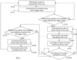
- Fig. 1 shows a flowchart of a method for regulating the activity of a core running at a given clock rate in accordance with an embodiment of the invention.
- core it is meant an electronic circuit (also referred to as electronic chip) large enough, relative to other components, to be worth a specific circuitry to handle its power integrity, for instance the consumption and the dissipation of the core.
- a core may be implemented on, but not limited to, a central processing unit (CPU) or a graphics processing unit (GPU). It is to be understood that the method may be implemented on a CPU or GPU comprising one or more cores, e.g. a multi-core CPU.
- a module of a core is a functional block of the core that performs a specific function.
- the terms clock rate refer to the rate in cycles per second or the frequency (measured in hertz) of the clock in any synchronous electronic circuit, e.g. a CPU or GPU.
- the core is run (or oscillates) at a given frequency.
- Regulating the activity of a core means that the usage of the core is adjusted, e.g. by maintaining at least one parameter of the core above or below a given level.
- the method comprises monitoring a value of a voltage of the core.
- the voltage is a critical parameter for a safe operating of the core.
- the monitored parameter is a parameter whose variations must remain above or below a given level in order to avoid a crash or even a physical destruction of the core.
- the method further comprises determining whether the monitored value reaches a trigger value.
- the trigger value is a value that, once reached by the monitored value, involves the initiating of a reaction for regulating the activity of the core. The determination may be performed by a comparison between the monitored value and the trigger value.
- the clock rate of the core is modified by decreasing the ratio of active cycles of the clock, and the core is run at the clock rate modified by decreasing the ratio of active cycles of the clock.
- the clock rate of the core is modified by increasing the ratio of active cycles of the clock, and the core then runs at the clock rate modified by increasing the ratio of active cycles of the clock.
- the method allows an adaptative scheme wherein, in case of too important variation of a critical parameter, the active clock cycles of the core clock are reduced so that the critical parameter is keep at an acceptable level, thus avoiding the crash of the core.
- the critical parameter keeps or reaches again a level considered as acceptable (that is, the core can perform its task with out crashing)
- no active clock cycles are suppressed so that the core can deliver its full performances.
- the method thus provides auto-adaptability to any varying parameter the core, especially to any critical parameter of the core.
- the method provides optimal core performance, that is, with minimal performances low.
- a value of a voltage of the module of the core is monitored. It is to be understood that the monitoring may concern one or several cores. Monitoring the value of a voltage means that a scaled analogue or digital signal that represents the real-time available state of the parameter is checked.
- the monitored parameter value is the voltage of the module of the core, the voltage and the temperature are indeed critical parameters that must remain in acceptable levels in order to avoid a defect of the core.
- the monitored value is compared with a trigger value.
- the trigger value is a threshold (or trigger threshold) that determines when the activity of the core has to be regulated.
- the trigger value is thus a trigger threshold from which the value of the voltage has to be maintained at an acceptable level. More precisely, the trigger value is selected slightly close to a critical value that causes the crash of the core when this critical value is reached.
- the critical parameter is the voltage of the core
- the monitored value of the parameter is the real-time available voltage of module of the core
- the trigger value is a voltage chosen so that it is sufficiently above the voltage for which the core crashes.
- step S120 it is determined whether the monitored value reaches the trigger value, as a result of the comparing step S110. In other words, it is checked whether the monitored value is below the trigger threshold defined by the trigger value. Since the monitored parameter is the voltage of the core, it is determined whether the value representative of the voltage of the core drops below a voltage threshold.
- steps S 130-160 of the method are carried out.
- the steps S100 to S120 are repeated.
- the clock rate of the core is modified as a result of the determination (or detection) that the monitored value has reached the trigger value.
- the modification of the clock scheme of the core is carried out by decreasing the ratio of active cycles of the clock. This amounts to say that the clock rate of the core is decreased by decreasing the ratio of active cycles of the clock.
- An active cycle is a period of time during which the core performs at least one instruction. Thus, active cycles are suppressed, and a new regular clock is recreated, usually at a rational ratio to ease an implementation with clock-gating, but not necessarily.
- step S140 the core is run at the modified clock rate, that is, a new regular clock recreated at step S130 is sent to the core.
- a typical example of ratio is to suppress one active cycle of the clock every two cycles. For instance, if one cycle every two is suppressed, this results to the creation of a halved frequency clock. It is to be understood that any ratio may be contemplated.
- the frequency reduction should be set to give compromise between a low enough frequency that ensures that the core with its reduced frequency is correctly regulated, and a high enough frequency, that avoids to impact too much the performances of the system.
- the recreated clock should preserve a duty-cycle of 50%-50%, that is, 50% of the active cycles are suppressed. For instance, the clock signals would look the next:
- the core is run at a reduced frequency.
- step S 150 it is counted a number of cycles carried out the by the clock of the core that runs at the clock rate modified by decreasing the ratio of active cycles of the clock.
- the counting starts once the core is run at the reduced frequency and is performed while the number of cycle does not reach a predetermined value or until it is determined that the monitored value reaches a second time (or again) the trigger value.
- the counter is reset to zero when the counting starts, and the predetermined value is a positive real number.
- step S160 it is determined whether the number of cycle reaches the predetermined value. It is to be understood that the determination is continuously performed. When the number of cycle reaches the predetermined value, the steps S130 to S160 are repeated. This means that the ratio of active cycles of the clock is decreased again in order to provide a new modified clock rate. It is to be understood that the new modified clock rate is lower that the former one. The core is then run at the new modified clock rate. In addition, the counter may be reset to zero when a new decrease of the ratio is performed.
- the ratio of active cycles of the clock of the core is progressively lowered, and as a result of the successive decreases of the ratio of active cycles, the monitored value reaches again the trigger value.
- this allows to improve auto-adaptability to any varying parameter the core (especially to any critical parameter of the core), including technologic production variations, while provides optimal core performance, that is, with minimal performances low.
- the predetermined value may be dynamically determined according to the current ratio of active cycles of the clock of the core. By this way, it is possible to refine a bit further the decreasing of the ratio of active cycles.
- the counter may be a timer counting a time elapsed between the current time and the time at which the core is run at the modified clock rate. It this case, when a predetermined time has elapsed and the monitored value has not reached a second time (or again) the trigger value, the steps S130 to S160 are repeated until the monitored value reaches a second time the trigger value.
- the predetermined time may be dynamically determined according to the current ratio of active cycles of the clock of the core. Again, this allows to refine the decrease of the ratio of active cycles.
- the steps S150 and S160 may not be implemented. Therefore, while the monitored value of the parameter reaches the trigger value, that is, while the monitored value remains above or below the threshold defined by the trigger value, the core runs continuously at the modified clock rate of step S130.
- the ratio of active cycles of the core should be selected sufficiently low in order to ensure that the frequency is reduced enough for restoring the core in a stable state, typically a ratio of one of two of the active cycles may be used.
- step S170 it is determined whether the monitored value reaches a second time the trigger value. This amounts to say that the monitored value reaches again or another time the trigger value. In other term, it is tested whether the monitored value of the critical parameter has currently an acceptable level. If this is not the case, then the core continues to run at the modified clock rate of steps S130-160. If the critical parameter is tested as having an acceptable level, the ratio of active cycle of the clock is increased (S180), and the core is then run at the clock rate modified by increasing the ratio of active cycles of the clock (S190). This amounts to say that the clock rate of the core is increased by increasing the ratio of active cycles of the clock. One could also say that the clock rate of the core is increased.
- any ratio of active cycle of the clock may be selected when increased.
- the ratio of active cycles of the clock is increased to the full ratio of active cycles of the clock, that is, all the active cycles of the clock are reestablished.
- this allows the core to work at its best capacities, that is, the core is fully active.
- the method may be repeated in order to ensure that the critical parameter remains at an acceptable level, that is, above or under a trigger value.
- the monitoring of the value of the parameter of the core may be a continuous process, which involves that there is no interruption in determining whether the monitored value reaches or reaches a second time (or again) the trigger value.
- the method according to the invention advantageously creates a reaction loop providing auto-adaptability to varying condition, for instance:
- the trigger value may be a predetermined value, e.g. a voltage threshold or a temperature threshold.
- the trigger value may be dynamically determined according to at least one intrinsic condition of the core such as the current clock rate, the decreased or increased ratio of active cycles of the clock, a reaction time between the determining step and the clock rating step.
- this makes it possible to refine when the regulation of the core has to be triggered.
- the definition of the trigger value is a compromise between the stability of the core (provided by an early trigger) and the performance of the core (provided by a late trigger).
- the transition between the current clock rate to the modified clock rate of the core may depend on a reaction time.
- the reaction time may be defined as a number of cycles of the core that elapsed between the point in time at which the monitored value reaches the trigger value (S120) or reaches a second time the trigger value (S170), and the point in time at which the core is run at the modified (decreased or increased) clock rate.
- the reaction time should be should be designed to be as fast as possible to allow the frequency reduction to act as fast as possible after a triggered voltage drop. Indeed, an increased reaction time leads to have an earlier trigger of the regulation of the core.
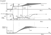
- Figs. 2 to 4 show graphics depicting comparison between a voltage-gating regulator as known in the art and a voltage-gating regulator in accordance with an embodiment of the invention.
- the curves relative to the method known in the art are shown in doted lines, and the curves relative to an embodiment of the present invention are shown in plain lines.
- the CPU has an initial activity which is low 200 until an interrupt occurs on the CPU 202.
- the interrupt causes a rise of the frequency of the core 204 so that the interrupt can be processed by the core.
- the rise of the frequency of the core causes a drop 304 of the voltage from a nominal level 300-302, as shown on FIG. 3 .
- the rise of the frequency of the core further causes a variation of the current arriving at the core as depicted on FIG. 4 : the consumption of current is low 400 while the CPU has a low frequency and increases 402 when the frequency rises.
- a trigger value 304 here a trigger voltage.
- the frequency of the core is reduced of 50%.
- the point 204 corresponds to the point in time at which the frequency of the clock of the core is reduced, that is, the point in time 304 on FIG. 3 at which the trigger value is reached by the monitored voltage.
- the method as known in the art keeps the frequency reduced during a period which starts at point 204 and ends at point 208.
- This period comprises several cycle of the clock, e.g. 1000 cycles. It is noticeable that the frequency is kept reduced even if the voltage of the core has reached a second time the voltage trigger; indeed, the voltage of the core reaches the trigger value only between points 304-308 on FIG. 3 . Then, as shown on FIG. 2 , the frequency of the core rises slowly from point 208 until it reaches its nominal value on point 210. Meanwhile, the voltage of the core rises progressively until it reaches its nominal value. However, the nominal value of the voltage is reached before the frequency reaches its nominal value. In other term, the core does not recover its full capacity even if its voltage is no more close from the trigger voltage. As a result, performances of the CPU are reduced despite the fact that the critical parameter (here the voltage of the CPU) is at an acceptable level.
- the critical parameter here the voltage of the CPU
- the monitored value (the voltage of the core) reaches a second time the trigger value at point 306 on FIG. 3 , which leads to modifying the clock rate of the core by increasing the ratio of active cycles of the clock and clock rating the core with the clock rate modified by increasing the ratio of active cycles of the clock.
- the ratio of active cycles of the core is decreased and the core is another time run at a reduced frequency. Consequently, the voltage of the core increases and reaches again the trigger value so that the core is run at a clock rate modified by increasing the ratio of active cycles of the clock.
- the ratio of active cycle is decreased and increased successively according to the value of the monitored voltage of the core: the method according to the invention is repeated several times until the voltage is definitively above the trigger voltage. It results from the repetition of the method that the voltage of the core oscillates around the trigger value until the voltage is definitively above the trigger voltage. However, the voltage of the core falls slower and slower and rises faster and faster, til recovery at point 312. During the oscillation phase 314 on FIG. 3 , the voltage oscillates around the trigger value (the trigger voltage). The low voltage guaranties that the current pumped from the last capacitance of the current source of the core and arriving at the core is maximal. Referring now to FIG.
- the plain line shows that the arriving current to the core is more important with the method according to the invention that with the method known in the art, as emphasized by the hatched area 404. Therefore, as the arrival of current is maximal, the performances are maximal, and an interrupt causing the rise of the frequency of the core can be processed more quickly. In fact, the frequency and the activity of the core rise as fast as the current, thus providing maximal performances for the core.
- the CPU 400 may comprise a core 410.
- the CPU may further comprise a sensor 420 operatively coupled with the core and adapted to monitor a value of a parameter of the core.
- the sensor may also be implemented on the core.
- the sensor may be able to operate a comparison between the monitored value and a trigger value for determining whether the monitored value reaches a trigger value.
- the CPU may comprise a clock-gating module 430 operatively coupled with the core and adapted to increase or decrease the ratio of active cycles of the clock for modifying the clock rate of the core.
- the clock-gating module may be also adapted to run the core at the modified clock rate.
- the clock-gating module may be operatively coupled with the sensor so that the sensor may transmit to the clock-gating module the monitored value and or the result of the determination whether or not the monitored value reaches a trigger value.
- the CPU may also comprise a counter 440 able to count a number of cycles of the clock of the core.
- the counter may be implanted on the CPU and operatively coupled with the clock-gating module.
- the counter may also be implemented by the clock-gating module.
- the clock-gating module may be implemented by logical gates on the CPU It is to be understood that this advantageously limits the area required on the CPU for implementing the clock-gating module.
- the clock-gating module may comprise the sensor. It is therefore possible to put the sensor and the clock-gating module very close to the core it-self, thus allowing to obtain better measures of the sensors.
- the method may be performed based on a computer program comprising instructions for performing the method.
- the program may be executable on a programmable device.
- the application program may be implemented in a high-level procedural or object-oriented programming language, or in assembly or machine language if desired. In any case, the language may be a compiled or interpreted language.
- the program may be a full installation program, or an update program. In the latter case, the program is an update program that updates a programmable device, previously programmed for performing parts of the method, to a state wherein the device is suitable for performing the whole method.
- the program may be recorded on a data storage medium.
- the data storage medium may be any memory adapted for recording computer instructions.
- the data storage medium may thus be any form of non volatile memory, including by way of example semiconductor memory devices, such as EPROM, EEPROM, and flash memories.
Landscapes
- Engineering & Computer Science (AREA)
- Theoretical Computer Science (AREA)
- Physics & Mathematics (AREA)
- General Engineering & Computer Science (AREA)
- General Physics & Mathematics (AREA)
- Human Computer Interaction (AREA)
- Microcomputers (AREA)
- Power Sources (AREA)
- Electrotherapy Devices (AREA)
Claims (9)
- Verfahren zur Regulierung der Aktivität eines Kerns, der mit einer gegebenen Taktrate eines Anfangstakts läuft, wobei das Verfahren Folgendes umfasst:- Überwachen (S100) eines Werts einer Spannung des Kerns,- Bestimmen, ob der überwachte Wert einen Auslösewert erreicht;- wenn der überwachte Wert den Auslösewert erreicht (S120):o Ändern, durch ein Clock-Gating-Modul, der Taktrate des Kerns (S130) durch Verringern des Verhältnisses von aktiven Zyklen eines Takts, der an den Kern gesendet wird, zu Gesamtzyklen des Anfangstakts durch Unterdrücken aktiver Zyklen des Anfangstakts; undo Betreiben des Kerns mit der Taktrate, die geändert wurde (S140) durch Verringern des Verhältnisses von aktiven Zyklen des Takts, der an den Kern gesendet wird, zu Gesamtzyklen des Anfangstakts;- wenn der überwachte Wert ein zweites Mal den Auslösewert erreicht (S170):o Ändern, durch das Clock-Gating-Modul, der Taktrate des Kerns (S180) durch Erhöhen des Verhältnisses von aktiven Zyklen des Takts, der an den Kern gesendet wird, zu Gesamtzyklen des Anfangstakts; undo Betreiben des Kerns mit der Taktrate (S190), die geändert wurde durch Erhöhen des Verhältnisses von aktiven Zyklen des Takts, der an den Kern gesendet wird, zu Gesamtzyklen des Anfangstakts.
- Verfahren nach Anspruch 1, wobei, wenn der überwachte Wert den Auslösewert erreicht, die Schritte des Änderns der Taktrate und des Betreibens des Kerns mit der geänderten Taktrate wiederholt werden, bis der überwachte Wert das zweite Mal den Auslösewert erreicht.
- Verfahren nach Anspruch 2, wobei die Wiederholung der Schritte von Ändern der Taktrate und Anwenden der geänderten Taktrate auf den Kern, bis der überwachte Wert das zweite Mal den Auslösewert erreicht, Folgendes umfasst:- Zählen einer Anzahl von Zyklen (S150), die von dem Takt ausgeführt werden, der an den Kern gesendet wird;- Ändern der Taktrate durch erneutes Verringern (S130) des Verhältnisses von aktiven Zyklen des Takts, der an den Kern gesendet wird, zu Gesamtzyklen des Anfangstakts, wenn die Anzahl gezählter Zyklen einen vorbestimmten Wert erreicht (S160);- Betreiben des Kerns mit der Taktrate (S140), die durch erneutes Verringern des Verhältnisses von aktiven Zyklen des Takts, der an den Kern gesendet wird, zu Gesamtzyklen des Anfangstakts geändert wird.
- Verfahren nach einem der Ansprüche 1 bis 3, wobei, wenn der überwachte Wert das zweite Mal den Auslösewert erreicht, das Verhältnis von aktiven Zyklen des Takts, der an den Kern gesendet wird, zu Gesamtzyklen des Anfangstakts auf das volle Verhältnis von aktiven Zyklen des Takts, der an den Kern gesendet wird, zu Gesamtzyklen des Anfangstakts erhöht wird.
- Verfahren nach einem der Ansprüche 1 bis 4, wobei der Auslösewert dynamisch in Abhängigkeit von mindestens einem der Folgenden bestimmt wird:- der Verringerung des Verhältnisses von aktiven zu Gesamtzyklen des Takts;- der Erhöhung des Verhältnisses von aktiven zu Gesamtzyklen des Takts;- einer Reaktionszeit zwischen dem Bestimmungsschritt und dem Taktratenänderungsschritt.
- System zur Regulierung der Aktivität eines Kerns (410), der mit einer gegebenen Taktrate eines Anfangstakts betrieben wird, wobei das System Folgendes umfasst:- einen Spannungssensor (420), der betriebsbereit mit dem Kern gekoppelt ist und dazu angepasst ist, einen Wert einer Spannung des Kerns zu überwachen und zu bestimmen, ob der überwachte Wert einen Auslösewert erreicht;- ein Clock-Gating-Modul (430), das betriebsbereit mit dem Kern gekoppelt ist und zu Folgendem angepasst ist:∘ Ändern der Taktrate des Kerns durch Verringern des Verhältnisses von aktiven Zyklen eines Takts, die an den Kern (410) gesendet werden, zu Gesamtzyklen des Anfangstakts durch Unterdrücken aktiver Zyklen des Anfangstakts und Betreiben des Kerns mit der Taktrate, die geändert wurde durch Verringern des Verhältnisses von aktiven Zyklen des Takts, der an den Kern gesendet wird, zu Gesamtzyklen des Anfangstakts, wenn der Sensor bestimmt hat, dass der überwachte Wert den Auslösewert erreicht hat; undo Ändern der Taktrate des Kerns durch Erhöhen des Verhältnisses von aktiven Zyklen des Takts, der an den Kern gesendet wird, zu Gesamtzyklen des Anfangstakts und Betreiben des Kerns mit der Taktrate, die geändert wurde durch Erhöhen des Verhältnisses von aktiven Zyklen des Takts, der an den Kern gesendet wird, zu Gesamtzyklen des Anfangstakts, wenn der Sensor bestimmt hat, dass der überwachte Wert ein zweites Mal den Auslösewert erreicht hat.
- System nach Anspruch 6, ferner umfassend:- einen Zähler (440), der betriebsbereit mit dem Kern gekoppelt ist und dazu angepasst ist, eine Anzahl von Zyklen zu zählen, die von dem Takt, der an den Kern gesendet wird, ausgeführt werden, und wobei das Clock-Gating-Modul (430) ferner zu Folgendem angepasst ist:- Ändern der Taktrate durch erneutes Verringern des Verhältnisses von aktiven Zyklen des Takts, der an den Kern gesendet wird, zu Gesamtzyklen des Anfangstakts, wenn die Anzahl von Zyklen, die von dem Zähler gezählt werden, einen vorbestimmten Wert erreicht;- Betreiben des Kerns mit der Taktrate, die durch erneutes Verringern des Verhältnisses von aktiven Zyklen des Takts, der an den Kern gesendet wird, zu Gesamtzyklen des Anfangstakts geändert wurde.
- Verarbeitungseinheit (400) mit mindestens einem Kern, die das System nach einem der Ansprüche 6-7 integriert.
- Computerprogrammprodukt, umfassend ein computerlesbares Medium, auf dem sich ein Computerprogramm umfassend Programmbefehle befindet, wobei das Computerprogramm in eine Datenverarbeitungseinheit ladbar ist und dazu angepasst ist, eine Ausführung des Verfahrens nach einem der Ansprüche 1 bis 5 zu bewirken, wenn das Computerprogramm von der Datenverarbeitungseinheit ausgeführt wird.
Priority Applications (1)
| Application Number | Priority Date | Filing Date | Title |
|---|---|---|---|
| EP18214036.8A EP3480679B1 (de) | 2011-09-06 | 2011-09-06 | Regulierung der aktivität eines kerns |
Applications Claiming Priority (2)
| Application Number | Priority Date | Filing Date | Title |
|---|---|---|---|
| EP18214036.8A EP3480679B1 (de) | 2011-09-06 | 2011-09-06 | Regulierung der aktivität eines kerns |
| EP11306108.9A EP2568354B1 (de) | 2011-09-06 | 2011-09-06 | Regulierung der Aktivität eines Kerns |
Related Parent Applications (1)
| Application Number | Title | Priority Date | Filing Date |
|---|---|---|---|
| EP11306108.9A Division EP2568354B1 (de) | 2011-09-06 | 2011-09-06 | Regulierung der Aktivität eines Kerns |
Publications (3)
| Publication Number | Publication Date |
|---|---|
| EP3480679A1 EP3480679A1 (de) | 2019-05-08 |
| EP3480679B1 true EP3480679B1 (de) | 2024-11-27 |
| EP3480679C0 EP3480679C0 (de) | 2024-11-27 |
Family
ID=44674670
Family Applications (2)
| Application Number | Title | Priority Date | Filing Date |
|---|---|---|---|
| EP18214036.8A Active EP3480679B1 (de) | 2011-09-06 | 2011-09-06 | Regulierung der aktivität eines kerns |
| EP11306108.9A Active EP2568354B1 (de) | 2011-09-06 | 2011-09-06 | Regulierung der Aktivität eines Kerns |
Family Applications After (1)
| Application Number | Title | Priority Date | Filing Date |
|---|---|---|---|
| EP11306108.9A Active EP2568354B1 (de) | 2011-09-06 | 2011-09-06 | Regulierung der Aktivität eines Kerns |
Country Status (3)
| Country | Link |
|---|---|
| US (1) | US9442552B2 (de) |
| EP (2) | EP3480679B1 (de) |
| WO (1) | WO2013034646A2 (de) |
Families Citing this family (11)
| Publication number | Priority date | Publication date | Assignee | Title |
|---|---|---|---|---|
| US9449359B2 (en) * | 2012-09-13 | 2016-09-20 | Ati Technologies Ulc | Rendering settings in a multi-graphics processing unit system |
| US9471088B2 (en) | 2013-06-25 | 2016-10-18 | Intel Corporation | Restricting clock signal delivery in a processor |
| US9377836B2 (en) * | 2013-07-26 | 2016-06-28 | Intel Corporation | Restricting clock signal delivery based on activity in a processor |
| CN104424156A (zh) | 2013-09-09 | 2015-03-18 | 中兴通讯股份有限公司 | 处理器的核处理方法、装置及终端 |
| CN103941844A (zh) * | 2014-04-29 | 2014-07-23 | 联想(北京)有限公司 | 一种频率调整方法及电子设备 |
| JP6441166B2 (ja) * | 2015-05-15 | 2018-12-19 | ルネサスエレクトロニクス株式会社 | 半導体装置 |
| CN106293003A (zh) * | 2016-08-05 | 2017-01-04 | 广东工业大学 | 一种基于aov网关键路径查询的异构系统动态功耗优化方法 |
| CN107341089A (zh) * | 2017-06-29 | 2017-11-10 | 联想(北京)有限公司 | 调节电子设备的cpu频率的方法及系统 |
| JP6872440B2 (ja) * | 2017-06-30 | 2021-05-19 | ルネサスエレクトロニクス株式会社 | 半導体装置および半導体装置の制御方法 |
| US10782729B2 (en) * | 2017-11-30 | 2020-09-22 | Intel Corporation | Clock signal modulation for processors |
| US11209886B2 (en) | 2019-09-16 | 2021-12-28 | Microsoft Technology Licensing, Llc | Clock frequency adjustment for workload changes in integrated circuit devices |
Citations (6)
| Publication number | Priority date | Publication date | Assignee | Title |
|---|---|---|---|---|
| US6232820B1 (en) * | 1999-06-14 | 2001-05-15 | Intel Corporation | Method and apparatus for dynamic clock gating |
| US6552572B1 (en) * | 2001-10-24 | 2003-04-22 | Lsi Logic Corporation | Clock gating cell for use in a cell library |
| US20060093047A1 (en) * | 2004-11-04 | 2006-05-04 | International Business Machines Corporation | Circuit to reduce transient current swings during mode transitions of high frequency/high power chips |
| US20060132185A1 (en) * | 2004-12-21 | 2006-06-22 | Via Technologies, Inc. | Clock gating circuit |
| US20070097620A1 (en) * | 2005-10-31 | 2007-05-03 | Leech Phillip A | Heat sink verification |
| WO2007144808A2 (en) * | 2006-06-15 | 2007-12-21 | Nxp B.V. | A method of providing a clock frequency for a processor |
Family Cites Families (6)
| Publication number | Priority date | Publication date | Assignee | Title |
|---|---|---|---|---|
| US5978864A (en) * | 1997-06-25 | 1999-11-02 | Sun Microsystems, Inc. | Method for thermal overload detection and prevention for an intergrated circuit processor |
| US6509788B2 (en) * | 2001-03-16 | 2003-01-21 | Hewlett-Packard Company | System and method utilizing on-chip voltage controlled frequency modulation to manage power consumption |
| US7282966B2 (en) * | 2004-09-28 | 2007-10-16 | Intel Corporation | Frequency management apparatus, systems, and methods |
| US20060161375A1 (en) * | 2004-12-30 | 2006-07-20 | Allen Duberstein | Optimizing processing speed based on measured temperatures |
| US20070150765A1 (en) * | 2005-12-26 | 2007-06-28 | Takayuki Ochiai | Information processing apparatus having electronic device whose operating speed is controlled, and method of controlling the operating speed of the electronic device |
| US7263457B2 (en) * | 2006-01-03 | 2007-08-28 | Advanced Micro Devices, Inc. | System and method for operating components of an integrated circuit at independent frequencies and/or voltages |
-
2011
- 2011-09-06 EP EP18214036.8A patent/EP3480679B1/de active Active
- 2011-09-06 EP EP11306108.9A patent/EP2568354B1/de active Active
-
2012
- 2012-09-06 WO PCT/EP2012/067425 patent/WO2013034646A2/en not_active Ceased
- 2012-09-06 US US14/343,175 patent/US9442552B2/en active Active
Patent Citations (6)
| Publication number | Priority date | Publication date | Assignee | Title |
|---|---|---|---|---|
| US6232820B1 (en) * | 1999-06-14 | 2001-05-15 | Intel Corporation | Method and apparatus for dynamic clock gating |
| US6552572B1 (en) * | 2001-10-24 | 2003-04-22 | Lsi Logic Corporation | Clock gating cell for use in a cell library |
| US20060093047A1 (en) * | 2004-11-04 | 2006-05-04 | International Business Machines Corporation | Circuit to reduce transient current swings during mode transitions of high frequency/high power chips |
| US20060132185A1 (en) * | 2004-12-21 | 2006-06-22 | Via Technologies, Inc. | Clock gating circuit |
| US20070097620A1 (en) * | 2005-10-31 | 2007-05-03 | Leech Phillip A | Heat sink verification |
| WO2007144808A2 (en) * | 2006-06-15 | 2007-12-21 | Nxp B.V. | A method of providing a clock frequency for a processor |
Also Published As
| Publication number | Publication date |
|---|---|
| US20140223211A1 (en) | 2014-08-07 |
| US9442552B2 (en) | 2016-09-13 |
| EP3480679A1 (de) | 2019-05-08 |
| EP2568354A1 (de) | 2013-03-13 |
| WO2013034646A3 (en) | 2013-05-10 |
| WO2013034646A2 (en) | 2013-03-14 |
| EP2568354B1 (de) | 2018-12-26 |
| EP3480679C0 (de) | 2024-11-27 |
Similar Documents
| Publication | Publication Date | Title |
|---|---|---|
| EP3480679B1 (de) | Regulierung der aktivität eines kerns | |
| JP6125539B2 (ja) | リアルタイムシステムにおける動的電力管理 | |
| US9563226B2 (en) | Dynamic clock regulation based on duty cycle thresholds | |
| US9176572B2 (en) | System and method for controlling central processing unit power with guaranteed transient deadlines | |
| US9104411B2 (en) | System and method for controlling central processing unit power with guaranteed transient deadlines | |
| US9176563B2 (en) | Leakage variation aware power management for multicore processors | |
| TWI486754B (zh) | 用以控制供應電壓之方法及系統 | |
| US20130173946A1 (en) | Controlling power consumption through multiple power limits over multiple time intervals | |
| JPH10198456A (ja) | マイクロプロセッサ及びその最適化方法 | |
| US20100185878A1 (en) | Method for controlling power consumption and a device having power consumption capabilities | |
| WO2014123587A1 (en) | System and method for controlling central processing unit power with guaranteed transient deadlines | |
| EP3079036A1 (de) | Systeme, verfahren und vorrichtung zur steuerung der einschalt- oder hochfahrsequenz einer integrierten schaltung auf basis von energiegewinnungsbedingungen | |
| KR101578336B1 (ko) | 보장된 과도 데드라인들로 중앙 프로세싱 유닛 전력을 제어하기 위한 시스템 및 방법 | |
| US20110107115A1 (en) | Hardware based p-state control | |
| WO2025034297A1 (en) | Apparatus and methods for voltage droop detection in die architectures | |
| KR101755817B1 (ko) | 반도체 프로세서 장치를 위한 선제적 열 관리 방법 및 장치 | |
| JP5241450B2 (ja) | 半導体装置及びその異常検出方法 | |
| US7664976B2 (en) | Controlling circuit for controlling operating clock and/or driving voltage of logic circuit, and method thereof | |
| US10228752B2 (en) | Voltage scaling system with sleep mode | |
| CN1397859A (zh) | 内置复位功能的微型计算机 | |
| US9740259B2 (en) | Method for managing software application computing resources | |
| US12591266B2 (en) | Feedback-based clock frequency adjustment for dynamic clock voltage scaling | |
| CN119134229A (zh) | 一种过流故障重启方法、装置、设备、介质及产品 | |
| EP2821880A2 (de) | Energiekontrollsystem und Verfahren dafür | |
| JP2006189996A (ja) | 半導体装置 |
Legal Events
| Date | Code | Title | Description |
|---|---|---|---|
| PUAI | Public reference made under article 153(3) epc to a published international application that has entered the european phase |
Free format text: ORIGINAL CODE: 0009012 |
|
| STAA | Information on the status of an ep patent application or granted ep patent |
Free format text: STATUS: THE APPLICATION HAS BEEN PUBLISHED |
|
| AC | Divisional application: reference to earlier application |
Ref document number: 2568354 Country of ref document: EP Kind code of ref document: P |
|
| AK | Designated contracting states |
Kind code of ref document: A1 Designated state(s): AL AT BE BG CH CY CZ DE DK EE ES FI FR GB GR HR HU IE IS IT LI LT LU LV MC MK MT NL NO PL PT RO RS SE SI SK SM TR |
|
| STAA | Information on the status of an ep patent application or granted ep patent |
Free format text: STATUS: REQUEST FOR EXAMINATION WAS MADE |
|
| 17P | Request for examination filed |
Effective date: 20191029 |
|
| RBV | Designated contracting states (corrected) |
Designated state(s): AL AT BE BG CH CY CZ DE DK EE ES FI FR GB GR HR HU IE IS IT LI LT LU LV MC MK MT NL NO PL PT RO RS SE SI SK SM TR |
|
| STAA | Information on the status of an ep patent application or granted ep patent |
Free format text: STATUS: EXAMINATION IS IN PROGRESS |
|
| 17Q | First examination report despatched |
Effective date: 20200707 |
|
| REG | Reference to a national code |
Ref country code: DE Ref legal event code: R079 Ref document number: 602011075135 Country of ref document: DE Free format text: PREVIOUS MAIN CLASS: G06F0001320000 Ipc: G06F0001200000 Ref country code: DE Ref legal event code: R079 Free format text: PREVIOUS MAIN CLASS: G06F0001320000 Ipc: G06F0001200000 |
|
| GRAP | Despatch of communication of intention to grant a patent |
Free format text: ORIGINAL CODE: EPIDOSNIGR1 |
|
| STAA | Information on the status of an ep patent application or granted ep patent |
Free format text: STATUS: GRANT OF PATENT IS INTENDED |
|
| RIC1 | Information provided on ipc code assigned before grant |
Ipc: G06F 1/20 20060101AFI20240723BHEP |
|
| INTG | Intention to grant announced |
Effective date: 20240812 |
|
| GRAS | Grant fee paid |
Free format text: ORIGINAL CODE: EPIDOSNIGR3 |
|
| GRAA | (expected) grant |
Free format text: ORIGINAL CODE: 0009210 |
|
| STAA | Information on the status of an ep patent application or granted ep patent |
Free format text: STATUS: THE PATENT HAS BEEN GRANTED |
|
| AC | Divisional application: reference to earlier application |
Ref document number: 2568354 Country of ref document: EP Kind code of ref document: P |
|
| AK | Designated contracting states |
Kind code of ref document: B1 Designated state(s): AL AT BE BG CH CY CZ DE DK EE ES FI FR GB GR HR HU IE IS IT LI LT LU LV MC MK MT NL NO PL PT RO RS SE SI SK SM TR |
|
| REG | Reference to a national code |
Ref country code: GB Ref legal event code: FG4D |
|
| REG | Reference to a national code |
Ref country code: CH Ref legal event code: EP |
|
| REG | Reference to a national code |
Ref country code: IE Ref legal event code: FG4D |
|
| REG | Reference to a national code |
Ref country code: DE Ref legal event code: R096 Ref document number: 602011075135 Country of ref document: DE |
|
| U01 | Request for unitary effect filed |
Effective date: 20241210 |
|
| U07 | Unitary effect registered |
Designated state(s): AT BE BG DE DK EE FI FR IT LT LU LV MT NL PT RO SE SI Effective date: 20241219 |
|
| PG25 | Lapsed in a contracting state [announced via postgrant information from national office to epo] |
Ref country code: IS Free format text: LAPSE BECAUSE OF FAILURE TO SUBMIT A TRANSLATION OF THE DESCRIPTION OR TO PAY THE FEE WITHIN THE PRESCRIBED TIME-LIMIT Effective date: 20250327 Ref country code: HR Free format text: LAPSE BECAUSE OF FAILURE TO SUBMIT A TRANSLATION OF THE DESCRIPTION OR TO PAY THE FEE WITHIN THE PRESCRIBED TIME-LIMIT Effective date: 20241127 |
|
| PG25 | Lapsed in a contracting state [announced via postgrant information from national office to epo] |
Ref country code: ES Free format text: LAPSE BECAUSE OF FAILURE TO SUBMIT A TRANSLATION OF THE DESCRIPTION OR TO PAY THE FEE WITHIN THE PRESCRIBED TIME-LIMIT Effective date: 20241127 |
|
| PG25 | Lapsed in a contracting state [announced via postgrant information from national office to epo] |
Ref country code: NO Free format text: LAPSE BECAUSE OF FAILURE TO SUBMIT A TRANSLATION OF THE DESCRIPTION OR TO PAY THE FEE WITHIN THE PRESCRIBED TIME-LIMIT Effective date: 20250227 |
|
| PG25 | Lapsed in a contracting state [announced via postgrant information from national office to epo] |
Ref country code: GR Free format text: LAPSE BECAUSE OF FAILURE TO SUBMIT A TRANSLATION OF THE DESCRIPTION OR TO PAY THE FEE WITHIN THE PRESCRIBED TIME-LIMIT Effective date: 20250228 |
|
| PG25 | Lapsed in a contracting state [announced via postgrant information from national office to epo] |
Ref country code: PL Free format text: LAPSE BECAUSE OF FAILURE TO SUBMIT A TRANSLATION OF THE DESCRIPTION OR TO PAY THE FEE WITHIN THE PRESCRIBED TIME-LIMIT Effective date: 20241127 |
|
| PG25 | Lapsed in a contracting state [announced via postgrant information from national office to epo] |
Ref country code: RS Free format text: LAPSE BECAUSE OF FAILURE TO SUBMIT A TRANSLATION OF THE DESCRIPTION OR TO PAY THE FEE WITHIN THE PRESCRIBED TIME-LIMIT Effective date: 20250227 |
|
| PG25 | Lapsed in a contracting state [announced via postgrant information from national office to epo] |
Ref country code: SM Free format text: LAPSE BECAUSE OF FAILURE TO SUBMIT A TRANSLATION OF THE DESCRIPTION OR TO PAY THE FEE WITHIN THE PRESCRIBED TIME-LIMIT Effective date: 20241127 |
|
| PG25 | Lapsed in a contracting state [announced via postgrant information from national office to epo] |
Ref country code: SK Free format text: LAPSE BECAUSE OF FAILURE TO SUBMIT A TRANSLATION OF THE DESCRIPTION OR TO PAY THE FEE WITHIN THE PRESCRIBED TIME-LIMIT Effective date: 20241127 |
|
| PG25 | Lapsed in a contracting state [announced via postgrant information from national office to epo] |
Ref country code: CZ Free format text: LAPSE BECAUSE OF FAILURE TO SUBMIT A TRANSLATION OF THE DESCRIPTION OR TO PAY THE FEE WITHIN THE PRESCRIBED TIME-LIMIT Effective date: 20241127 |
|
| PLBE | No opposition filed within time limit |
Free format text: ORIGINAL CODE: 0009261 |
|
| STAA | Information on the status of an ep patent application or granted ep patent |
Free format text: STATUS: NO OPPOSITION FILED WITHIN TIME LIMIT |
|
| PGFP | Annual fee paid to national office [announced via postgrant information from national office to epo] |
Ref country code: GB Payment date: 20250929 Year of fee payment: 15 |
|
| 26N | No opposition filed |
Effective date: 20250828 |
|
| U20 | Renewal fee for the european patent with unitary effect paid |
Year of fee payment: 15 Effective date: 20250929 |