EP3480477A1 - Anordnung mit einem ersten, an einem zweiten bauteil festzulegenden bauteil, leuchte und verfahren - Google Patents
Anordnung mit einem ersten, an einem zweiten bauteil festzulegenden bauteil, leuchte und verfahren Download PDFInfo
- Publication number
- EP3480477A1 EP3480477A1 EP18190637.1A EP18190637A EP3480477A1 EP 3480477 A1 EP3480477 A1 EP 3480477A1 EP 18190637 A EP18190637 A EP 18190637A EP 3480477 A1 EP3480477 A1 EP 3480477A1
- Authority
- EP
- European Patent Office
- Prior art keywords
- component
- arrangement
- relative
- fixed
- connecting element
- Prior art date
- Legal status (The legal status is an assumption and is not a legal conclusion. Google has not performed a legal analysis and makes no representation as to the accuracy of the status listed.)
- Granted
Links
Images


Classifications
-
- F—MECHANICAL ENGINEERING; LIGHTING; HEATING; WEAPONS; BLASTING
- F21—LIGHTING
- F21S—NON-PORTABLE LIGHTING DEVICES; SYSTEMS THEREOF; VEHICLE LIGHTING DEVICES SPECIALLY ADAPTED FOR VEHICLE EXTERIORS
- F21S41/00—Illuminating devices specially adapted for vehicle exteriors, e.g. headlamps
- F21S41/30—Illuminating devices specially adapted for vehicle exteriors, e.g. headlamps characterised by reflectors
- F21S41/39—Attachment thereof
Definitions
- the invention relates to an arrangement with a first component to be fixed to a second component of the arrangement by means of a connecting element of the arrangement along a connecting axis, wherein an intermediate element is arranged between the first component and a head of the connecting element designed as a stop.
- Such an arrangement is used for example in motor vehicles.
- motor vehicle lights such as LED headlamps
- the reflector forms the first component of the arrangement and the heat sink, the second component.
- the two components are bolted together.
- a connecting element thus a screw is used.
- the screw typically has a head and a shaft.
- a screw has the disadvantage that during screwing, as soon as the head of the screw contacts the reflector, a torque acts on the reflector.
- the reflector can thus rotate relative to the heat sink.
- the object of the invention is therefore to provide an arrangement, a luminaire and a method which make it possible to fix a first component to a second component while maintaining a precision adjustment of the two components relative to each other.
- the object is achieved by an arrangement with a first component to be fixed to a second component of the arrangement by means of a connecting element of the arrangement along a connecting axis, wherein an intermediate element is arranged between the first component and a head of the connecting element designed as a stop, wherein the intermediate element is arranged by means of at least one of the first component independent element element relative to a rotation about the connecting axis relative to the second component rotatably fixed or fixed.
- the intermediate element can absorb a torque emanating from the connecting element and derive via the mold element to the second component.
- the torque can result in particular from a rotational movement of the head of the connecting element.
- the intermediate element can thus act as a torque receptacle, in particular as a torque receiving plate.
- the first component can remain torque-free - or at least essentially free of torque. It can thus be achieved that, during the fixing of the first component on the second component, no or essentially no forces and / or torques on the first component engage relative to the second component. If the first component is adjusted relative to the second component, this adjustment, in particular a possible precision adjustment, can be maintained.
- the intermediate element may be shaped like a disk. It can also have an elongated shape.
- the arrangement has at least two form elements, with which the intermediate element relative to the rotation about the connecting axis relative to the second component rotatably fixed or fixed.
- the mold element may have a circular cross-section.
- the mold element has a non-circular cross-section.
- a rotationally fixed fixing of the intermediate element on the second component can be achieved.
- a plurality of form elements may be spaced apart from one another and arranged parallel or substantially parallel to one another and preferably parallel or substantially parallel to the connection axis.
- the one or more form elements spaced the intermediate element and independently of the connecting element on the second component rotatably set.
- the first and the second component can be designed as elements of a motor vehicle light, in particular as a reflector and / or as a heat sink.
- the arrangement according to the invention can thus be formed in the motor vehicle light.
- the motor vehicle light can be designed, for example, as a headlight, in particular as an LED-based headlight or comprise such.
- the mold element can, in particular in addition to the connecting element, establish a connection between the second component and the intermediate element.
- the mold element may be formed on the second component or on the intermediate element.
- the shaped element can be formed as a projection of the second component or of the intermediate element.
- the shaped element may be formed on the second component. It can also be positively connected with at least one of these two elements, d. H. the second component and / or the intermediate element, be connected or connected.
- the form element is designed, for example, as a projection of the second component and can be positively connected to the intermediate element, in particular by plugging together, then the intermediate element can be fixed against rotation relative to the second component by means of the connecting element by simply plugging together with the aid of the fitting element.
- connection element is helical, in particular designed as a screw.
- the first and the second component may each have a, preferably to a respective other connecting element opening correspondingly positioned, connecting element opening for receiving the connecting element.
- the connecting element opening of the first component may be formed as a passage opening.
- the connecting element opening of the second component may be formed as a blind hole or as a passage opening.
- the connecting element can penetrate through the first component and penetrate into the second component, in particular through or be screwed.
- the first and the second component can thus be fixed particularly stable to each other.
- the head of the connecting element makes contact with the intermediate element during insertion, it may, especially due to friction, come to a transfer of torque to the intermediate element. This torque can thus be transferred via the intermediate element in the second component and derived from the second component.
- the first component may also have a mold element passage opening for receiving the mold element.
- the mold element passage opening may be located outside the connection axis.
- the first and the second component are adjustable relative to each other.
- the cross section of the shaped element passage opening in a plane perpendicular to the connection axis is at least partially larger than the cross section of the feature element.
- the connecting element opening may also have, at least in sections, a larger cross section than the connecting element assigned to it. In particular, it can have a larger diameter than a shank of the connecting element. Then, the first component can be displaced relative to the second component in a plane perpendicular to the connection axis and / or rotated and thus finely adjusted.
- the cross section of the shaped element passage opening in a plane perpendicular to the connecting axis at least partially larger than the cross section of the formula element can be filled in the resulting space within the mold element passage opening adhesive and / or filled.
- the mold element passage opening in particular the free space in its interior, can be used as a glue pot.
- the first component and the second component can be fixed in their relative position to one another by an adhesive.
- the adhesive may be electromagnetically curing, for example UV-curing. Then, the curing of the adhesive and thus the fixation can be done without contact.
- first and / or the second component made of a plastic, in particular an injection-moldable plastic, such as polycarbonate, are formed or have such.
- the first and / or the second component made of a plastic, in particular an injection-moldable plastic, such as polycarbonate, are formed or have such.
- at least one of the components for example the first component, in particular the reflector, can be produced by means of injection molding.
- the invention further relates to a luminaire with at least one arrangement according to the invention.
- a desired light image can be set and permanently determined, for example, particularly simply.
- the lamp may be formed as a motor vehicle lamp or include such, wherein preferably the first and / or the second component of the arrangement are formed by a reflector and / or by a heat sink or include such. It is also conceivable that the first and / or the second component as another element of a Motor vehicle light, for example, as a housing element, are formed or include such.
- the setting of a desired light image results in particularly high precision requirements for the relative positioning of a reflector relative to a heat sink and / or other elements. Even minimal deviations of the reflector from its nominal position can lead to significant deformities of the resulting light image. This particularly applies to LED-based luminaires.
- the reflector can thus be fixed, for example, on an associated cooling body, while maintaining a previous precision adjustment. This makes it possible to produce luminaires with a precisely adjusted light image in a particularly simple way.
- the intermediate element can be fixed to the one or more mold elements, in particular attached thereto.
- the method according to the invention provides, prior to assembly of the connecting element, the intermediate element as protection, in particular torque absorption and / or drainage, to install. If the connecting element is then mounted, for example screwed in, it can be prevented that a torque is transmitted from the connecting element, in particular a head of the connecting element, to the first component. The first component can thus remain relative to the second component in its intended relative position during assembly of the connecting element.
- Precise adjustment of the first relative to the second component can be achieved by adjusting the first component relative to the second component, in particular by means of an adjusting tool, before the intermediate element is fixed.
- the first and second components are components of a lamp of a motor vehicle
- the resulting photograph may be viewed and monitored during the precision adjustment.
- the first component can be displaced and / or rotated relative to the second component.
- first component is fixed to the second component by means of gluing.
- fixing by means of gluing can be done in particular a provisional fixation on the building then a final determination of the two components can be done together preferably by means of the connecting element.
- adhesive can be given in one or more formed as adhesive cups form element through holes. Before or particularly preferred thereafter, in particular as long as the adhesive has not yet hardened, the precision adjustment can take place.
- the adhesive is an electromagnetically curing adhesive, for example a UV-curing adhesive
- the adhesive can be cured by irradiation with electromagnetic radiation, for example UV light.
- the connecting element can then be mounted, for example screwed in, in order to achieve a desired, in particular permanent, final strength of the connection or fixing of the first component to the second component.
- the method can be used particularly advantageously if, as a component, in particular as a first component, a reflector and as another component, in particular as a second component, another element of a motor vehicle light, in particular a heat sink, or vice versa are used ,
- the method is not limited to the field of manufacture of luminaires, but can also be generally applied to the connection of two components to be fixed to each other. This is especially true when the two components are to be defined to each other precision-positioned.
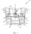
- Fig. 1 shows a detail of a schematically illustrated lamp 10.
- the lamp 10 is an LED-based motor vehicle light.
- the arrangement 12 has a first component 14 .
- the first component 14 is designed as a reflector.
- the first component 14 is made of an injection-moldable plastic, in particular polycarbonate.
- the first component 14 is fixed by means of a connecting element 24 of the arrangement 12 along a connecting axis V to a second component 16 .
- the second component 16 is designed as a heat sink.
- the first component 14 and the second component 16 are thus formed as elements of a motor vehicle lamp.
- the connecting element 24 is formed in this embodiment as a screw.
- the second component 16 ie the heat sink
- the two form elements 18 are thus regardless of the first component 14. They penetrate the first component 14 by a respectively associated with them, formed in the first component 14 for receiving the respective element element 18 formed element passage opening 20th
- the mold elements 18 as well as their each associated mold element passage openings 20 are each located outside of the connecting axis V.
- an intermediate element 22 in particular form-fitting, is arranged.
- the intermediate element 22 is arranged between the first component 14 and a trained as a stop head 26 of the connecting element 24, the intermediate element 22 is arranged.
- the head 26 is in Fig. 1 illustrated, assembled state of the connecting element 24 on the intermediate element 22 at.
- intermediate element 22 is fixed relative to the second component 16 relative to the second component 16 relative to a rotation about the connecting axis V by means of the two component elements independent of the first component 14.
- planes E Perpendicular to the connecting axis V, planes E are defined.
- the intermediate element 22 For receiving the mold elements 18, the intermediate element 22 also has two form element receptacles 19 .
- the form element receptacles 19 are formed as passage openings whose cross section corresponds to the cross section of the form elements 18.
- a positive connection between the mold elements 18 and the intermediate element 22 is formed.
- the intermediate element 22 is attached by means of the form element receptacles 19 to the mold elements 18 respectively assigned to them - and thus also to the second component 16.
- FIG. 2 to Fig. 4 schematically illustrated decomposition states of the arrangement 12 of the embodiment described so far.
- the presentation of the Fig. 5 corresponds to the representation of the arrangement according to Fig. 1 with the exception of an adhesive introduced into the assembly.
- Fig. 2 shows the second component 16, ie the heat sink, the Fig. 1 , To recognize in turn are arranged on the second component 16 and projecting from this form of elements 18th
- the second component 16 has a connecting element opening 28 , which is formed in this embodiment as a blind hole, in particular as a screw receptacle.
- the connecting element opening 28 serves to receive the connecting element 24 (FIG. Fig. 1 ) in the component 16.
- An upper side 30 of the second component 16 serves as a support surface for the first component 14 (FIG. Fig. 1 ), in particular as a reflector support surface.
- the top 30 is at least partially flat.
- the upper side 30 thus forms a reference geometry for referencing a zero position along the connecting axis V.
- Fig. 3 shows the second component 16 according to Fig. 2 to which the first component 14, that is the reflector, is placed.
- the mold element passage openings 20 have, at least in the portion with which the mold elements 18 protrude through the first component 14, a larger cross section than the respective cross section of the mold elements 18. As will be explained in more detail later, the mold element through holes 20 can thus be used as adhesive cups ,
- the first component 14 has a connection element opening 29 , which in this case has a larger cross section than a shaft of the connection element 24 (FIG. Fig. 1 ), with which the connecting element 24 protrudes through the first component 14 for fixing the first component 14 on the second component 16.
- the cross section of the connecting element opening 29 is not circular. This results in a free space or a game in particular for the connecting element 24th
- the first component 14 may be used in Fig. 3 shown disassembled state relative to the second component 16 in a plane perpendicular to the connection axis V level E and / or relative to the second component 16th to be turned around.
- the position and the position of the first component 14 relative to the second component 16 can be adjusted precisely, as long as the components 14, 16 are not fixed to each other, in particular as long as the connecting element 24 is not mounted and no other fixation is present.
- Fig. 4 is now a decomposition state shown, in which the intermediate member 22 is disposed above the first component 14 and in particular attached to the mold elements 18.
- the intermediate element 22 is formed as an elongate metal sheet. It has centrally a likewise formed as a passage opening connecting element opening 32 .
- the connecting element openings 28, 29, 32 are arranged in their respective components such that they are suitable for mounting the connecting element 24 (FIG. Fig. 1 ) are substantially aligned with each other. In particular, thus, the connecting element 24 can be inserted through the connecting element openings 28, 29, 32 or screwed into this.
- an adhesive 31 is mounted in the mold element through openings 20 of the first component 14.
- the adhesive 30 is a UV light-curing adhesive. I'm in the Fig. 4 shown decomposition state, this adhesive 31 is already cured by exposure to UV light.
- the first component 14 is fixed by the adhesive 31 on the second component at least against low shear or tensile forces or torques.
- the first and the second component 14, 16 are thus fixed relative to each other, at least against low loads or disturbing influences.
- FIG. 6 a schematic representation of the method according to the invention.
- the reference numerals of the preceding figures are used to designate the respective elements of the arrangement or luminaire according to the invention.
- the second component 16 is prepared for fixing the first component 14 thereto.
- the second component 16 is fixed, for example on an object holder and / or on a work table.
- a light image measuring device (not shown in the preceding figures), for example consisting of a light source and an image recording and evaluation unit for receiving a later reflected light image is put into operation.
- a second step 102 the first component 14 is placed on the second component 16.
- a coarse prepositioning which normally results automatically through the mold elements 18 in conjunction with the mold element through openings 20, is sufficient.
- the form element passage openings 20 designed as adhesive cups are filled with the adhesive 31, a UV-curing adhesive.
- the first and second components are precision positioned relative to each other.
- an adjustment tool in the Fig. 1 to Fig. 5 not shown.
- the connecting element opening 29 of the first component 14 serves as the point of application for the adjusting tool.
- the reflector that is to say the first component 14
- the reflector is displaced relative to the second component 16 and / or rotated until the measured light image , Preferably, except for a predetermined tolerance measure, coincides with a desired light image.
- the adhesive 31 is then cured by UV light irradiation.
- the intermediate element 22 is placed.
- the intermediate element 22 with respect to a rotation about the connecting axis V relative to the second component 16 rotatably fixed.
- a concluding step 106 the connecting element 24, that is to say the screw, is screwed into the second component 16 by the intermediate element 22 and the first component part 14.
- the first component 14 is fixed to the second component 16 by means of the connecting element 24 of the arrangement 12.
- the head 26 of the connector 24 approaches the intermediate member 22 until it finally contacts it. Even if the head 26 in this case exerts a torque on the intermediate element 22, thus the previous precision adjustment of the first component 14 remains fully maintained relative to the second component 16, since the torque on the second component 16 and away, for example, on the object holder or the work table, is passed.
- the components 14, 16 are displaced relative to each other in step 104 and / or rotated until they have a predetermined relative position and / or relative position, preferably to a predetermined tolerance measure, to each other.
- a predetermined relative position and / or relative position preferably to a predetermined tolerance measure, to each other.
- a direct position and / or position detection for example by an image acquisition and evaluation unit directed at the components 14, 16, can take place in order to monitor the displacement and / or rotation.
Landscapes
- Engineering & Computer Science (AREA)
- General Engineering & Computer Science (AREA)
- Non-Portable Lighting Devices Or Systems Thereof (AREA)
- Mounting And Adjusting Of Optical Elements (AREA)
- Fastening Of Light Sources Or Lamp Holders (AREA)
Abstract
Description
- Die Erfindung betrifft eine Anordnung mit einem ersten, an einem zweiten Bauteil der Anordnung mittels eines Verbindungselements der Anordnung entlang einer Verbindungsachse festzulegenden Bauteil, wobei zwischen dem ersten Bauteil und einem als Anschlag ausgebildeten Kopf des Verbindungselements ein Zwischenelement angeordnet ist.
- Eine solche Anordnung kommt beispielsweise bei Kraftfahrzeugen zur Anwendung. Insbesondere bei der Herstellung von Kraftfahrzeugleuchten, beispielsweise LED-Scheinwerfern, ist es üblich, einen Reflektor an beispielsweise einem Kühlkörper festzulegen. Dabei bildet der Reflektor das erste Bauteil der Anordnung und der Kühlkörper das zweite Bauteil. Typischerweise werden die beiden Bauteile miteinander verschraubt. Als Verbindungselement kommt somit eine Schraube zum Einsatz. Die Schraube weist typischerweise einen Kopf und einen Schaft auf.
- Eine Verschraubung birgt jedoch den Nachteil, dass während des Verschraubens, sobald der Kopf der Schraube den Reflektor kontaktiert, ein Drehmoment auf den Reflektor wirkt. Der Reflektor kann sich somit relativ zum Kühlkörper verdrehen.
- Um das jeweils gewünschte Lichtbild der Kraftfahrzeugleuchte zu erhalten, ist es erforderlich, vor der Verbindung der beiden Bauteile diese präzise relativ zueinander zu justieren. Somit besteht das Risiko, dass durch die Verschraubung bzw. Verbindung der beiden Bauteile das zunächst präzise eingestellte Lichtbild wieder verändert wird.
- Eine Herstellung der Kraftfahrzeugleuchte ist somit erheblich erschwert.
- Aus der
DE 203 17 863 U1 ist eine Anordnung mit wenigstens zwei über ein Verbindungselement verbindbaren Bauteilen bekannt. Bei dieser Anordnung ist ein Scheibenelement vorgesehen, das an dem an ihm direkt angrenzenden Bauteil drehbar angelenkt ist. - Aufgabe der Erfindung ist es daher, eine Anordnung, eine Leuchte und ein Verfahren anzubieten, die es ermöglichen, ein erstes Bauteil an einem zweiten Bauteil unter Aufrechterhaltung einer Präzisionsjustierung der beiden Bauteile relativ zueinander festzulegen.
- Gelöst wird die Aufgabe durch eine Anordnung mit einem ersten, an einem zweiten Bauteil der Anordnung mittels eines Verbindungselements der Anordnung entlang einer Verbindungsachse festzulegenden Bauteil, wobei zwischen dem ersten Bauteil und einem als Anschlag ausgebildeten Kopf des Verbindungselements ein Zwischenelement angeordnet ist, wobei das Zwischenelement mittels wenigstens eines vom ersten Bauteil unabhängigen Formelements bezüglich einer Drehung um die Verbindungsachse relativ zum zweiten Bauteil drehfest festlegbar oder festgelegt ist.
- Somit kann das Zwischenelement ein vom Verbindungselement ausgehendes Drehmoment aufnehmen und über das Formelement an das zweite Bauteil ableiten. Dabei kann das Drehmoment insbesondere von einer Drehbewegung des Kopfes des Verbindungselementes herrühren.
- Das Zwischenelement kann somit als Drehmomentaufnahme, insbesondere als Drehmomentaufnahmeblech, wirken. Insbesondere kann das erste Bauteil drehmomentfrei - oder zumindest im Wesentlichen drehmomentfrei - bleiben. Somit kann erreicht werden, dass während des Festlegens des ersten Bauteils am zweiten Bauteil keine oder im Wesentlichen keine Kräfte und/oder Drehmomente am ersten Bauteil relativ zum zweiten Bauteil angreifen. Ist das erste Bauteil relativ zum zweiten Bauteil justiert, so kann diese Justierung, insbesondere eine etwaige Präzisionsjustierung, aufrechterhalten bleiben.
- Das Zwischenelement kann scheibenförmig geformt sein. Es kann auch eine längliche Form aufweisen.
- Auch ist denkbar, dass die Anordnung wenigstens zwei Formelemente aufweist, mit denen das Zwischenelement bezüglich der Drehung um die Verbindungsachse relativ zum zweiten Bauteil drehfest festlegbar oder festgelegt ist.
- Das Formelement kann einen kreisförmigen Querschnitt aufweisen.
- Bei einer Ausführungsform der Anordnung mit nur einem einzigen Formelement ist es besonders bevorzugt, wenn das Formelement einen nichtkreisförmigen Querschnitt aufweist. Somit lässt sich eine drehfeste Festlegung des Zwischenelements am zweiten Bauteil erreichen.
- Sind mehrere Formelemente vorgesehen, so können diese voneinander beabstandet und parallel oder im Wesentlichen parallel zueinander und vorzugsweise parallel oder im Wesentlichen parallel zur Verbindungsachse angeordnet sein. Somit können das oder die Formelemente das Zwischenelement beabstandet und unabhängig vom Verbindungselement am zweiten Bauteil drehfest festlegen.
- Das erste und das zweite Bauteil können als Elemente einer Kraftfahrzeugleuchte, insbesondere als Reflektor und/oder als Kühlkörper, ausgebildet sein. Die erfindungsgemäße Anordnung kann somit in der Kraftfahrzeugleuchte ausgebildet sein. Die Kraftfahrzeugleuchte kann beispielsweise als Scheinwerfer, insbesondere als LED-basierter Scheinwerfer ausgebildet sein oder einen solchen umfassen.
- Das Formelement kann, insbesondere zusätzlich zum Verbindungselement, eine Verbindung zwischen dem zweiten Bauteil und dem Zwischenelement herstellen. Dazu kann das Formelement am zweiten Bauteil oder am Zwischenelement ausgebildet sein.
- Besonders bevorzugt kann das Formelement als Vorsprung des zweiten Bauteils oder des Zwischenelements ausgebildet sein.
- Insbesondere kann das Formelement am zweiten Bauteil ausgebildet sein. Es kann auch formschlüssig mit wenigstens einem dieser beiden Elemente, d. h. dem zweiten Bauteil und/oder dem Zwischenelement, verbindbar oder verbunden sein.
- Ist das Formelement beispielsweise als Vorsprung des zweiten Bauteils ausgebildet und mit dem Zwischenelement formschlüssig, insbesondere durch Zusammenstecken, verbindbar, so kann das Zwischenelement vor dem Verbinden mittels des Verbindungselements durch einfaches Zusammenstecken mit Hilfe des Formelements relativ zum zweiten Bauteil drehfest festgelegt werden.
- Eine besonders einfache Verbindung der beiden Bauteile lässt sich erzielen, wenn das Verbindungselement schraubenförmig, insbesondere als Schraube, ausgebildet ist.
- Das erste und das zweite Bauteil können jeweils eine, vorzugsweise zu einer jeweils anderen Verbindungselementöffnung korrespondierend positionierte, Verbindungselementöffnung zur Aufnahme des Verbindungselements aufweisen. Beispielsweise kann die Verbindungselementöffnung des ersten Bauteils als Durchgangsöffnung ausgebildet sein. Die Verbindungselementöffnung des zweiten Bauteils kann als Sackloch oder als Durchgangsöffnung ausgebildet sein.
- Somit kann das Verbindungselement durch das erste Bauteil durch- und in das zweite Bauteil hineindringen, insbesondere durch- bzw. eingeschraubt sein. Das erste und das zweite Bauteil können somit besonders stabil aneinander festgelegt werden. Kontaktiert der Kopf des Verbindungselements beim Eindrehen das Zwischenelement, so kann es, insbesondere reibungsbedingt, zu einer Übertragung eines Drehmoments auf das Zwischenelement kommen. Dieses Drehmoment kann somit über das Zwischenelement in das zweite Bauelement übergeleitet und vom zweiten Bauelement abgeleitet werden.
- Das erste Bauteil kann auch eine Formelementdurchgangsöffnung zur Aufnahme des Formelements aufweisen. Die Formelementdurchgangsöffnung kann sich außerhalb der Verbindungsachse befinden.
- Auch kann vorgesehen sein, dass, insbesondere bei nicht montiertem Verbindungselement, das erste und das zweite Bauteil relativ zueinander justierbar sind.
- Dazu kann insbesondere vorgesehen sein, dass der Querschnitt der Formelementdurchgangsöffnung in einer Ebene senkrecht zur Verbindungsachse zumindest abschnittsweise größer ist als der Querschnitt des Formelements. Auch die Verbindungselementöffnung kann zumindest abschnittsweise einen größeren Querschnitt als das ihr zugeordnete Verbindungselement aufweisen. Sie kann insbesondere einen größeren Durchmesser aufweisen als ein Schaft des Verbindungselements. Dann kann das erste Bauteil relativ zum zweiten Bauteil in einer Ebene senkrecht zur Verbindungsachse verlagert und/oder gedreht und somit feinjustiert werden.
- Ist der Querschnitt der Formelementdurchgangsöffnung in einer Ebene senkrecht zur Verbindungsachse zumindest abschnittsweise größer als der Querschnitt des Formelements, kann in den entstehenden Freiraum innerhalb der Formelementdurchgangsöffnung Klebstoff einfüllbar sein und/oder eingefüllt sein. Somit kann die Formelementdurchgangsöffnung, insbesondere der Freiraum in ihrem Inneren, als Klebetopf genutzt werden.
- Für eine temporäre Fixierung, insbesondere solange das Verbindungselement noch nicht endgültig montiert ist, können das erste Bauteil und das zweite Bauteil in ihrer relativen Lage zueinander durch einen Klebstoff fixiert sein.
- Insbesondere kann der Klebstoff elektromagnetisch härtend, beispielsweise UV-Licht-härtend, sein. Dann können die Aushärtung des Klebstoffs und damit die Fixierung berührungslos erfolgen.
- Denkbar ist auch, dass das erste und/oder das zweite Bauteil aus einem Kunststoff, insbesondere einem spritzgussfähigen Kunststoff, beispielsweise Polycarbonat, gebildet sind oder einen solchen aufweisen. Somit kann wenigstens eines der Bauteile, beispielsweise das erste Bauteil, insbesondere der Reflektor, mittels Spritzguss hergestellt sein.
- Die Erfindung betrifft des Weiteren eine Leuchte mit wenigstens einer erfindungsgemäßen Anordnung. Bei einer solchen Leuchte kann beispielsweise besonders einfach ein gewünschtes Lichtbild eingestellt und dauerhaft festgelegt werden.
- Insbesondere kann die Leuchte als Kraftfahrzeugleuchte ausgebildet sein oder eine solche umfassen, wobei vorzugsweise das erste und/oder das zweite Bauteil der Anordnung durch einen Reflektor und/oder durch einen Kühlkörper gebildet sind oder einen solchen umfassen. Denkbar ist auch, dass das erste und/oder das zweite Bauteil als ein anderes Element einer Kraftfahrzeugleuchte, beispielsweise als Gehäuseelement, ausgebildet sind oder ein solches umfassen.
- Zur Herstellung einer Leuchte eines Kraftfahrzeugs, beispielsweise eines Front- und/oder eines Rückscheinwerfers, ergeben sich bei der Einstellung eines gewünschten Lichtbildes besonders hohe Präzisionsanforderungen an die Relativpositionierung eines Reflektors relativ zu einem Kühlkörper und/oder zu anderen Elementen. Bereits minimale Abweichungen des Reflektors von seiner Sollposition können zu erheblichen Missgestaltungen des resultierenden Lichtbildes führen. Dies betrifft in besonderem Maße auch LED-basierte Leuchten. Durch Verwendung einer erfindungsgemäßen Anordnung kann somit der Reflektor, beispielsweise an einem ihm zugeordneten Kühlkörper, unter Beibehaltung einer vorhergehenden Präzisionsjustierung festgelegt werden. Somit lassen sich auf besonders einfache Weise Leuchten mit präzise justiertem Lichtbild herstellen.
- In den Rahmen der Erfindung fällt des Weiteren ein Verfahren zur Festlegung eines ersten Bauteils an einem zweiten Bauteil einer erfindungsgemäßen Anordnung und/oder einer erfindungsgemäßen Leuchte, wobei vor Festlegen des ersten Bauteils am zweiten Bauteil mittels des Verbindungselements der Anordnung das Zwischenelement bezüglich einer Drehung um die Verbindungsachse relativ zum zweiten Bauteil drehfest festgelegt wird.
- Zur Festlegung des Zwischenelements am zweiten Bauteil kann beispielsweise das Zwischenelement an dem oder den Formelementen festgelegt, insbesondere auf diese aufgesteckt, werden.
- Mit anderen Worten sieht das erfindungsgemäße Verfahren vor, vor Montage des Verbindungselements das Zwischenelement als Schutz, insbesondere Drehmomentaufnahme und/oder -ableitung, anzubringen. Wird dann das Verbindungselement montiert, beispielsweise eingeschraubt, kann verhindert werden, dass ein Drehmoment von dem Verbindungselement, insbesondere einem Kopf des Verbindungselements, auf das erste Bauteil übertragen wird. Das erste Bauteil kann somit relativ zum zweiten Bauteil in seiner vorgesehenen Relativposition während der Montage des Verbindungselements verbleiben.
- Eine Präzisionsjustierung des ersten relativ zum zweiten Bauteil lässt sich erreichen, indem vor Festlegen des Zwischenelements das erste Bauteil relativ zum zweiten Bauteil, insbesondere mittels eines Justierwerkzeugs, justiert wird.
- Handelt es sich beispielsweise bei dem ersten und dem zweiten Bauteil um Bauteile einer Leuchte eines Kraftfahrzeugs, kann während der Präzisionsjustierung das sich ergebende Lichtbild betrachtet und überwacht werden. Zur Justierung kann das erste Bauteil relativ zum zweiten Bauteil verlagert und/oder gedreht werden.
- Denkbar ist auch, dass das erste Bauteil am zweiten Bauteil mittels Klebens fixiert wird. Durch Fixierung mittels Klebens kann insbesondere eine vorläufige Fixierung erfolgen, auf der aufbauend dann eine endgültige Festlegung der beiden Bauteile aneinander vorzugsweise mittels des Verbindungselements erfolgen kann.
- Dazu kann beispielsweise Klebstoff in einen oder mehrere als Klebetöpfe ausgebildete Formelementdurchgangsöffnungen gegeben werden. Zuvor oder besonders bevorzugt danach, insbesondere solange der Klebstoff noch nicht ausgehärtet ist, kann die Präzisionsjustierung erfolgen.
- Ist der Klebstoff ein elektromagnetisch härtender Klebstoff, beispielsweise ein UV-Licht-härtender Klebstoff, so kann anschließend der Klebstoff durch Bestrahlen mit elektromagnetischer Bestrahlung, beispielsweise UV-Licht, ausgehärtet werden.
- Somit können Herstellungsfehler aufgrund von geringfügigen Störungen des Betriebsablaufes, beispielsweise durch Erschütterungen, vermieden werden. Im Anschluss daran kann dann das Verbindungselement montiert, beispielsweise eingeschraubt, werden, um eine gewünschte, insbesondere dauerhafte Endfestigkeit der Verbindung bzw. Festlegung des ersten Bauteils am zweiten Bauteil zu erreichen.
- Aufgrund der sich ergebenden Präzisionsanforderungen kann das Verfahren besonders vorteilhaft angewendet werden, wenn als ein Bauteil, insbesondere als erstes Bauteil, ein Reflektor und als ein anderes Bauteil, insbesondere als zweites Bauteil, ein weiteres Element einer Kraftfahrzeugleuchte, insbesondere ein Kühlkörper, oder umgekehrt verwendet werden.
- Das Verfahren ist jedoch nicht auf den Bereich der Herstellung von Leuchten beschränkt, sondern kann auch allgemein zur Verbindung zweier aneinander festzulegender Bauteile angewendet werden. Dies gilt insbesondere, wenn die zwei Bauteile zueinander präzisionspositioniert festgelegt werden sollen.
- Weitere Merkmale und Vorteile der Erfindung ergeben sich aus der nachfolgenden detaillierten Beschreibung eines Ausführungsbeispiels der Erfindung anhand der Figuren der Zeichnung, die erfindungswesentliche Einzelheiten zeigen, sowie aus den Ansprüchen.
- Die einzelnen Merkmale können je einzeln für sich oder zu mehreren in beliebigen Kombinationen bei Varianten der Erfindung verwirklicht sein. In der schematischen Zeichnung sind Ausführungsbeispiele der Erfindung dargestellt, welche in der nachfolgenden Beschreibung näher erläutert werden.
- Es zeigen:
- Fig. 1
- einen Detailausschnitt einer Leuchte mit einer erfindungsgemäßen Anordnung;
- Fig. 2
- eine Detailansicht auf ein zweites Bauteil der Anordnung der
Fig.1 ; - Fig. 3
- eine Detailansicht auf ein auf das zweite Bauteil der
Fig. 2 aufgesetztes erstes Bauteil; - Fig. 4
- eine Detailansicht analog der
Fig. 3 , wobei zusätzlich ein Zwischenelement auf das erste Bauteil aufgesetzt ist; - Fig. 5
- einen der
Fig. 1 entsprechenden Detailausschnitt, jedoch mit einem Klebstoff, und - Fig. 6
- eine schematische Darstellung des erfindungsgemäßen Verfahrens.
- Zur Erleichterung des Verständnisses der Erfindung sind soweit möglich in allen Figuren gleiche Bezugszeichen für sich jeweils entsprechende Elemente eingetragen.
-
Fig. 1 zeigt einen Detailausschnitt einer schematisch dargestellten Leuchte 10. Die Leuchte 10 ist eine LED-basierte Kraftfahrzeugleuchte. - Insbesondere ist eine erfindungsgemäße Anordnung 12 der Leuchte 10 zu erkennen. Die Anordnung 12 weist ein erstes Bauteil 14 auf. Das erste Bauteil 14 ist als Reflektor ausgebildet. Das erste Bauteil 14 ist aus einem spritzgussfähigen Kunststoff, insbesondere Polycarbonat, hergestellt.
- Das erste Bauteil 14 ist mittels eines Verbindungselements 24 der Anordnung 12 entlang einer Verbindungsachse V an einem zweiten Bauteil 16 festgelegt.
Das zweite Bauteil 16 ist als Kühlkörper ausgebildet. Das erste Bauteil 14 und das zweite Bauteil 16 sind somit als Elemente einer Kraftfahrzeugleuchte ausgebildet. - Das Verbindungselement 24 ist in diesem Ausführungsbeispiel als Schraube ausgebildet.
- Zu erkennen ist des Weiteren, dass das zweite Bauteil 16, d. h. der Kühlkörper, zwei Formelemente 18 aufweist. Sie sind jeweils als Vorsprung des zweiten Bauteils 16 ausgebildet. Sie weisen eine dom- bzw. zapfenförmige Gestalt auf. Die beiden Formelemente 18 sind somit unabhängig vom ersten Bauteil 14. Sie durchdringen das erste Bauteil 14 durch jeweils eine ihnen jeweils zugeordnete, im ersten Bauteil 14 zur Aufnahme des jeweiligen Formelements 18 ausgebildete Formelementdurchgangsöffnung 20. Die Formelemente 18 sowie die ihnen jeweils zugeordneten Formelementdurchgangsöffnungen 20 befinden sich jeweils außerhalb der Verbindungsachse V.
- An den beiden Formelementen 18 ist ein Zwischenelement 22, insbesondere formschlüssig, angeordnet. Dabei ist zwischen dem ersten Bauteil 14 und einem als Anschlag ausgebildeten Kopf 26 des Verbindungselements 24 das Zwischenelement 22 angeordnet. Somit liegt der Kopf 26 im in
Fig. 1 dargestellten, montierten Zustand des Verbindungselements 24 an dem Zwischenelement 22 an. - Zu erkennen ist, dass das Zwischenelement 22 mittels der beiden vom ersten Bauteil 14 unabhängigen Formelemente 18 bezüglich einer Drehung um die Verbindungsachse V relativ zum zweiten Bauteil 16 drehfest festgelegt ist.
- Senkrecht zur Verbindungsachse V sind Ebenen E definiert.
- Auch ohne montiertes Verbindungselement 24 kann das Zwischenelement 22 aufgrund der Formelemente 18 relativ zum zweiten Bauelement 16 weder in einer der Ebenen E, d. h. relativ zur Verbindungsachse V oder zu einer zu dieser parallelen Drehachse, gedreht werden, noch kann es in einer der Ebenen E verlagert werden. Als einzige freie Bewegungsdimension des Zwischenelements 22 verbleibt diesem somit auch in diesem Fall zumindest im Wesentlichen eine Verlagerung parallel zur Verbindungsachse V.
- Zur Aufnahme der Formelemente 18 weist das Zwischenelement 22 ferner zwei Formelementaufnahmen 19 auf. Die Formelementaufnahmen 19 sind als Durchgangsöffnungen gebildet, deren Querschnitt dem Querschnitt der Formelemente 18 entspricht. Somit ist eine formschlüssige Verbindung zwischen den Formelementen 18 und dem Zwischenelement 22 gebildet. Insbesondere ist das Zwischenelement 22 mittels der Formelementaufnahmen 19 auf die diesen jeweils zugeordneten Formelemente 18 - und damit auch auf das zweite Bauteil 16 - aufgesteckt.
- Zur weiteren Erläuterung des Aufbaus der Anordnung 12 zeigen die nachfolgend beschriebenen
Fig. 2 bis Fig. 4 schematisch dargestellte Zerlegungszustände der Anordnung 12 der bislang beschriebenen Ausführungsform. Die Darstellung derFig. 5 entspricht der Darstellung der Anordnung gemäßFig. 1 mit Ausnahme eines in die Anordnung eingebrachten Klebstoffs. -
Fig. 2 zeigt das zweite Bauteil 16, d. h. den Kühlkörper, derFig. 1 . Zu erkennen sind wiederum die am zweiten Bauteil 16 angeordneten und von diesem abragenden Formelemente 18. - Das zweite Bauteil 16 weist eine Verbindungselementöffnung 28 auf, die in diesem Ausführungsbeispiel als Sackloch, insbesondere als Schraubenaufnahme, ausgebildet ist. Die Verbindungselementöffnung 28 dient zur Aufnahme des Verbindungselements 24 (
Fig. 1 ) im Bauteil 16. Eine Oberseite 30 des zweiten Bauteils 16 dient als Auflagefläche für das erste Bauteil 14 (Fig. 1 ), insbesondere als Reflektorauflagefläche. Die Oberseite 30 ist zumindest bereichsweise eben ausgebildet. Die Oberseite 30 bildet somit eine Referenzgeometrie zur Referenzierung einer Null-Lage entlang der Verbindungsachse V. -
Fig. 3 zeigt das zweite Bauteil 16 gemäßFig. 2 , auf das das erste Bauteil 14, das heißt der Reflektor, aufgesetzt ist. - Die Formelementdurchgangsöffnungen 20 weisen, zumindest in dem Abschnitt, mit dem die Formelemente 18 durch das erste Bauteil 14 ragen, einen größeren Querschnitt auf als der jeweilige Querschnitt der Formelemente 18. Wie später noch näher erläutert wird, können die Formelementdurchgangsöffnungen 20 somit als Klebetöpfe genutzt werden.
- Weiter weist das erste Bauteil 14 eine Verbindungselementöffnung 29 auf, die in diesem Falle einen größeren Querschnitt aufweist als ein Schaft des Verbindungselements 24 (
Fig. 1 ), mit dem das Verbindungselement 24 durch das erste Bauteil 14 zur Festlegung des ersten Bauteils 14 am zweiten Bauteil 16 ragt. Insbesondere ist der Querschnitt der Verbindungselementöffnung 29 nicht kreisförmig ausgebildet. Somit ergibt sich ein Freiraum bzw. ein Spiel insbesondere für das Verbindungselement 24. - Das erste Bauteil 14 kann im in
Fig. 3 dargestellten Zerlegungszustand relativ zum zweiten Bauteil 16 in einer zur Verbindungsachse V senkrechten Ebene E verlagert und/oder relativ zum zweiten Bauteil 16 gedreht werden. Insbesondere kann die Position und die Lage des ersten Bauteils 14 relativ zum zweiten Bauteil 16 präzisionsjustiert werden, solange die Bauteile 14, 16 nicht aneinander festgelegt sind, insbesondere solange das Verbindungselement 24 nicht montiert ist und keine anderweitige Fixierung vorliegt. - In der
Fig. 4 ist nun ein Zerlegungszustand abgebildet, bei dem über dem ersten Bauteil 14 das Zwischenelement 22 angeordnet und insbesondere auf die Formelemente 18 aufgesteckt ist. - Zu erkennen ist, dass das Zwischenelement 22 als längliches Blech ausgebildet ist. Es weist zentral eine ebenfalls als Durchgangsöffnung ausgebildete Verbindungselementöffnung 32 auf. Die Verbindungselementöffnungen 28, 29, 32 sind derart in ihren jeweiligen Bauelementen angeordnet, dass sie zur Montage des Verbindungselements 24 (
Fig. 1 ) zueinander im Wesentlichen fluchten. Insbesondere kann somit das Verbindungselement 24 durch die Verbindungselementöffnungen 28, 29, 32 hindurchgesteckt oder in diese eingeschraubt werden. - Des Weiteren ist zu erkennen, dass in den Formelementdurchgangsöffnungen 20 des ersten Bauteils 14 ein Klebstoff 31 angebracht ist. Der Klebstoff 30 ist ein UV-Licht-härtender Klebstoff. Im in der
Fig. 4 dargestellten Zerlegungszustand ist dieser Klebstoff 31 bereits mittels Bestrahlen durch UV-Licht ausgehärtet. - Das erste Bauteil 14 ist durch den Klebstoff 31 am zweiten Bauteil zumindest gegenüber geringen Schub- oder Zugkräften oder Drehmomenten festgelegt. Das erste und das zweite Bauteil 14, 16 sind somit relativ zueinander, zumindest gegenüber geringen Belastungen oder Störeinflüssen, fixiert.
- Im Unterschied zur Darstellung der
Fig. 1 weist die Anordnung 12 gemäßFig. 5 den - nunmehr ausgehärteten - Klebstoff 31 auf. - Zu erkennen ist, dass im Gegensatz zum Zustand gemäß der
Fig. 4 das Verbindungselement 24 durch die Verbindungselementöffnungen 28, 29, 32 (Fig. 4 ) durch- bzw. eingeschraubt ist. - Abschließend zeigt
Fig. 6 eine schematische Darstellung des erfindungsgemäßen Verfahrens. Zum besseren Verständnis werden wiederum die Bezugszeichen der vorangehenden Figuren zur Bezeichnung der jeweiligen Elemente der erfindungsgemäßen Anordnung bzw. Leuchte verwendet. - In einem ersten Schritt 100 wird das zweite Bauteil 16 zur Festlegung des ersten Bauteils 14 an diesem vorbereitet. Insbesondere wird das zweite Bauteil 16, beispielsweise an einer Objekthalterung und/oder auf einem Arbeitstisch, fixiert. Eine Lichtbildmessvorrichtung (in den vorangehenden Figuren nicht dargestellt), beispielsweise bestehend aus einer Lichtquelle und einer Bildaufnahme- und -auswertungseinheit zur Aufnahme eines später reflektierten Lichtbildes wird in Betrieb genommen.
- In einem zweiten Schritt 102 wird das erste Bauteil 14 auf das zweite Bauteil 16 aufgesetzt. Hierzu genügt zunächst eine grobe Vorpositionierung, die sich im Regelfall selbsttätig durch die Formelemente 18 in Verbindung mit den Formelementdurchgangsöffnungen 20 ergibt. Anschließend werden die als Klebetöpfe ausgebildeten Formelementdurchgangsöffnungen 20 mit dem Klebstoff 31, einem UV-Licht härtenden Klebstoff, befüllt.
- In einem nachfolgenden Schritt 104 werden das erste und das zweite Bauteil relativ zueinander präzisionspositioniert. Dazu wird ein Justierwerkzeug (in den
Fig. 1 bis Fig. 5 nicht dargestellt) verwendet. Als Angriffspunkt für das Justierwerkzeug dient die Verbindungselementöffnung 29 des ersten Bauteils 14. Bei gleichzeitiger Betrachtung des mittels der Lichtbildmessvorrichtung gemessenen Lichtbildes wird der Reflektor, das heißt das erste Bauteil 14, relativ zum zweiten Bauteil 16 verlagert, und/oder gedreht, bis das gemessene Lichtbild, vorzugsweise bis auf ein vorgegebenes Toleranzmaß, mit einem Soll-Lichtbild übereinstimmt. Der Klebstoff 31 wird sodann mittels UV-Lichtbestrahlung ausgehärtet. - Das Justierwerkzeug wird nun entfernt.
- Anschließend wird das Zwischenelement 22 aufgesetzt. Dabei wird, insbesondere mittels der Formelemente 18, das Zwischenelement 22 bezüglich einer Drehung um die Verbindungsachse V relativ zum zweiten Bauteil 16 drehfest festgelegt.
- In einem abschließenden Schritt 106 wird das Verbindungselement 24, das heißt die Schraube, durch das Zwischenelement 22 und das erste Bauteilteil 14 in das zweite Bauteil 16 eingeschraubt. Somit wird das erste Bauteil 14 am zweiten Bauteil 16 mittels des Verbindungselements 24 der Anordnung 12 festgelegt.
- Während des Einschraubens nähert sich der Kopf 26 des Verbindungselements 24 dem Zwischenelement 22, bis er schließlich dieses kontaktiert. Selbst wenn der Kopf 26 dabei ein Drehmoment auf das Zwischenelement 22 ausübt, bleibt somit dennoch die vorangehende Präzisionsjustierung des ersten Bauteils 14 relativ zum zweiten Bauteil 16 vollumfänglich aufrechterhalten, da das Drehmoment auf das zweite Bauteil 16 und von dort weg, beispielsweise auf die Objekthalterung oder den Arbeitstisch, geleitet wird.
- Bei einer Variante des Verfahrens werden die Bauteile 14, 16 im Schritt 104 relativ zueinander verlagert und/oder gedreht, bis sie eine vorgegebene Relativposition und/oder Relativlage, vorzugsweise bis auf ein vorgegebenes Toleranzmaß, zueinander aufweisen. Bei dieser Verfahrensvariante kann auf die Lichtbildmessvorrichtung und die Erfassung eines Lichtbilds sowie auf die damit verbundenen Vorbereitungen verzichtet werden. Anstelle dessen kann eine direkte Positions- und/oder Lageerfassung, beispielsweise durch eine auf die Bauteile 14, 16 gerichtete Bildaufnahme- und -auswertungseinheit, erfolgen, um die Verlagerung und/oder Drehung zu überwachen.
Claims (14)
- Anordnung (12) mit einem ersten, an einem zweiten Bauteil (16) der Anordnung (12) mittels eines Verbindungselements (24) der Anordnung (12) entlang einer Verbindungsachse (V) festzulegenden Bauteil (14), wobei zwischen dem ersten Bauteil (14) und einem als Anschlag ausgebildeten Kopf (26) des Verbindungselements (24) ein Zwischenelement (22) angeordnet ist,
dadurch gekennzeichnet,
dass das Zwischenelement (22) mittels wenigstens eines vom ersten Bauteil (14) unabhängigen Formelements (18) bezüglich einer Drehung um die Verbindungsachse (V) relativ zum zweiten Bauteil (16) drehfest festlegbar oder festgelegt ist. - Anordnung nach Anspruch 1, dadurch gekennzeichnet, dass das erste (14) und das zweite Bauteil (16) als Elemente einer Kraftfahrzeugleuchte, insbesondere als Reflektor und/oder als Kühlkörper, ausgebildet sind.
- Anordnung nach einem der vorhergehenden Ansprüche, dadurch gekennzeichnet, dass das Formelement (18) als Vorsprung des zweiten Bauteils (16) oder des Zwischenelements (22) ausgebildet ist.
- Anordnung nach einem der vorhergehenden Ansprüche, dadurch gekennzeichnet, dass das Formelement (18) am zweiten Bauteil (16) ausgebildet ist.
- Anordnung nach einem der vorhergehenden Ansprüche, dadurch gekennzeichnet, dass das Verbindungselement (24) schraubenförmig, insbesondere als Schraube, ausgebildet ist.
- Anordnung nach einem der vorhergehenden Ansprüche, dadurch gekennzeichnet, dass das erste Bauteil (14) eine Formelementdurchgangsöffnung (20) zur Aufnahme des Formelements (18) aufweist.
- Anordnung nach dem vorhergehenden Anspruch, dadurch gekennzeichnet, dass der Querschnitt der Formelementdurchgangsöffnung (20) in einer Ebene (E) senkrecht zur Verbindungsachse (V) zumindest abschnittsweise größer ist als der Querschnitt des Formelements (18).
- Anordnung nach einem der vorhergehenden Ansprüche, dadurch gekennzeichnet, dass das erste Bauteil (14) und das zweite Bauteil (16) in ihrer relativen Lage zueinander durch einen Klebstoff (31) fixiert sind.
- Anordnung nach einem der vorhergehenden Ansprüche, dadurch gekennzeichnet, dass das erste (14) und/oder das zweite Bauteil (16) aus einem Kunststoff, insbesondere einem spritzgussfähigen Kunststoff, beispielsweise Polycarbonat, gebildet sind oder einen solchen aufweisen.
- Leuchte (10) mit wenigstens einer Anordnung (12) nach einem der vorhergehenden Ansprüche.
- Leuchte nach dem vorhergehenden Anspruch, dadurch gekennzeichnet, dass die Leuchte (10) als Kraftfahrzeugleuchte ausgebildet ist oder eine solche umfasst, wobei vorzugsweise das erste (14) und/oder das zweite Bauteil (16) der Anordnung (12) durch einen Reflektor und/oder durch einen Kühlkörper gebildet sind oder einen solchen umfassen.
- Verfahren zur Festlegung eines ersten Bauteils (14) an einem zweiten Bauteil (16) einer Anordnung (12) nach einem der Ansprüche 1 bis 9 und/oder einer Leuchte (10) nach einem der Ansprüche 10 oder 11,
dadurch gekennzeichnet,
dass vor Festlegen des ersten Bauteils (14) am zweiten Bauteil (16) mittels des Verbindungselements (24) der Anordnung (12) das Zwischenelement (22) bezüglich einer Drehung um die Verbindungsachse (V) relativ zum zweiten Bauteil (16) drehfest festgelegt wird. - Verfahren nach dem vorhergehenden Anspruch, dadurch gekennzeichnet, dass vor Festlegen des Zwischenelements (22) das erste Bauteil (14) relativ zum zweiten Bauteil (16), insbesondere mittels eines Justierwerkzeugs, justiert wird.
- Verfahren nach einem der Ansprüche 12 oder 13, dadurch gekennzeichnet, dass das erste Bauteil (14) relativ zum zweiten Bauteil (16) durch Kleben fixiert wird.
Applications Claiming Priority (1)
| Application Number | Priority Date | Filing Date | Title |
|---|---|---|---|
| DE102017125712.8A DE102017125712A1 (de) | 2017-11-03 | 2017-11-03 | Anordnung mit einem ersten, an einem zweiten Bauteil festzulegenden Bauteil, Leuchte und Verfahren |
Publications (2)
| Publication Number | Publication Date |
|---|---|
| EP3480477A1 true EP3480477A1 (de) | 2019-05-08 |
| EP3480477B1 EP3480477B1 (de) | 2022-02-09 |
Family
ID=63556119
Family Applications (1)
| Application Number | Title | Priority Date | Filing Date |
|---|---|---|---|
| EP18190637.1A Active EP3480477B1 (de) | 2017-11-03 | 2018-08-24 | Anordnung mit einem ersten, an einem zweiten bauteil festzulegenden bauteil, leuchte und verfahren |
Country Status (4)
| Country | Link |
|---|---|
| EP (1) | EP3480477B1 (de) |
| CN (1) | CN109751567B (de) |
| DE (1) | DE102017125712A1 (de) |
| MX (1) | MX2018013269A (de) |
Citations (4)
| Publication number | Priority date | Publication date | Assignee | Title |
|---|---|---|---|---|
| EP0239440A1 (de) * | 1986-02-24 | 1987-09-30 | Valeo Vision | Einstellungseinrichtung, zum Beispeil für Fahrzeugleuchte |
| EP0346237A1 (de) * | 1988-06-10 | 1989-12-13 | Regie Nationale Des Usines Renault | Klammer zum Befestigen eines Plastikteils |
| DE10048279A1 (de) * | 2000-09-29 | 2002-04-25 | Audi Ag | Einrichtung zum reproduzierbaren Befestigen eines ersten Bauteiles an einem zweiten Bauteil |
| DE20317863U1 (de) * | 2003-11-19 | 2004-04-01 | Automotive Lighting Reutlingen Gmbh | Anordnung mit wenigstens zwei über ein Verbindungselement verbindbaren Bauteilen |
Family Cites Families (9)
| Publication number | Priority date | Publication date | Assignee | Title |
|---|---|---|---|---|
| DE10124563A1 (de) * | 2001-05-14 | 2002-11-28 | Deutsch Zentr Luft & Raumfahrt | Positioniereinrichtung |
| DE102005033709B4 (de) * | 2005-03-16 | 2021-12-16 | OSRAM Opto Semiconductors Gesellschaft mit beschränkter Haftung | Lichtemittierendes Modul |
| DE202006012577U1 (de) * | 2006-08-11 | 2007-12-20 | Brose Fahrzeugteile Gmbh & Co. Kommanditgesellschaft, Coburg | Aggregateträger zum Einbau in einer Türstruktur eine Kraftfahrzeugtür |
| DE102011051681B4 (de) * | 2011-07-08 | 2023-09-28 | HELLA GmbH & Co. KGaA | Einstellvorrichtung für Scheinwerfer |
| FR2979970B1 (fr) * | 2011-09-13 | 2019-11-29 | Valeo Vision | Dispositif d'eclairage et/ou de signalisation pour vehicule automobile |
| DE102012202933A1 (de) * | 2012-02-27 | 2013-08-29 | Osram Gmbh | Beleuchtungseinrichtung |
| US8500185B1 (en) * | 2012-03-02 | 2013-08-06 | GM Global Technology Operations LLC | Decklid hinge counterbalance assembly having a straight end torque rod with infinite rotational adjustment |
| KR20160056087A (ko) * | 2014-11-11 | 2016-05-19 | 엘지이노텍 주식회사 | 발광 장치 |
| AT518108B1 (de) * | 2015-12-18 | 2017-11-15 | Zkw Group Gmbh | Verfahren zur Herstellung einer formschlüssigen Verbindung zwischen zwei Bauteilen einer Kraftfahrzeugbeleuchtungsvorrichtung mithilfe eines bauteilseitigen Verbindungselements |
-
2017
- 2017-11-03 DE DE102017125712.8A patent/DE102017125712A1/de not_active Withdrawn
-
2018
- 2018-08-24 EP EP18190637.1A patent/EP3480477B1/de active Active
- 2018-09-26 CN CN201811121907.8A patent/CN109751567B/zh active Active
- 2018-10-30 MX MX2018013269A patent/MX2018013269A/es unknown
Patent Citations (4)
| Publication number | Priority date | Publication date | Assignee | Title |
|---|---|---|---|---|
| EP0239440A1 (de) * | 1986-02-24 | 1987-09-30 | Valeo Vision | Einstellungseinrichtung, zum Beispeil für Fahrzeugleuchte |
| EP0346237A1 (de) * | 1988-06-10 | 1989-12-13 | Regie Nationale Des Usines Renault | Klammer zum Befestigen eines Plastikteils |
| DE10048279A1 (de) * | 2000-09-29 | 2002-04-25 | Audi Ag | Einrichtung zum reproduzierbaren Befestigen eines ersten Bauteiles an einem zweiten Bauteil |
| DE20317863U1 (de) * | 2003-11-19 | 2004-04-01 | Automotive Lighting Reutlingen Gmbh | Anordnung mit wenigstens zwei über ein Verbindungselement verbindbaren Bauteilen |
Also Published As
| Publication number | Publication date |
|---|---|
| CN109751567B (zh) | 2022-08-23 |
| CN109751567A (zh) | 2019-05-14 |
| EP3480477B1 (de) | 2022-02-09 |
| MX2018013269A (es) | 2019-08-12 |
| DE102017125712A1 (de) | 2019-05-09 |
Similar Documents
| Publication | Publication Date | Title |
|---|---|---|
| DE102005057116B4 (de) | Vorrichtung zur Ausrichtung eines Strukturbauteils eines Kraftfahrzeugs | |
| DE19956756C2 (de) | Einstellbarer Mitnehmer für einen Fensterheber einer rahmenlosen Fahrzeugtür | |
| WO2009132755A1 (de) | Verfahren und befestigungsvorrichtung zum befestigen eines fahrzeugteils an einem fahrzeug | |
| EP3720735B1 (de) | Montagemodul für eine fahrzeugleuchte | |
| EP1677012B1 (de) | Kunststoffbauteil | |
| EP0962280A2 (de) | Ausrichteinrichtung | |
| DE102014009257B4 (de) | Exzenterelement und Verfahren zum Einstellen einer Relativposition eines Anbauteils | |
| DE19719915C2 (de) | Gabelglied für einen Leitwerkanschluß | |
| EP0087623B1 (de) | Verfahren zur Herstellung einer auf einer Gewindespindel laufenden Doppelmutter | |
| EP2706385B1 (de) | Befestigungsvorrichtung und Verfahren zur Befestigung | |
| DE102013209111B4 (de) | Einspannvorrichtung, insbesondere zur Aufnahme und zum Einspannen eines Bauteils, sowie Einspannsystem mit einer solchen Einspannvorrichtung | |
| EP3480477B1 (de) | Anordnung mit einem ersten, an einem zweiten bauteil festzulegenden bauteil, leuchte und verfahren | |
| EP1912827A1 (de) | Vorrichtung zur justierbaren befestigung eines scheinwerfers | |
| EP1621846B1 (de) | Vormontage eines Sensors | |
| DE102005045086A1 (de) | Befestigungsvorrichtung für eine Stoßstangen-Leuchten-Baueinheit | |
| DE3841661A1 (de) | Optische baugruppe fuer kraftfahrzeuge mit ausfluchtbarer befestigung | |
| DE20212282U1 (de) | Kraftfahrzeugscheinwerfer mit mehreren verstellbaren Leuchteinheiten | |
| DE3523384C2 (de) | ||
| DE102011051681B4 (de) | Einstellvorrichtung für Scheinwerfer | |
| DE102004005978A1 (de) | Verfahren und Vorrichtung zur Montage von Scheinwerfern an Montageträgern | |
| DE10104757B4 (de) | Befestigungsvorrichtung zur verstellbaren Befestigung eines Fahrzeugteils | |
| EP2197092A1 (de) | Verfahren zum Montieren eines Resolvers und elektrische Maschine | |
| EP3354907B1 (de) | Rastscheibensatz | |
| DE102021000445A1 (de) | Einstellvorrichtung zum Einstellen der Lage eines Exzenters einer Exzenterschraube an einem Fahrzeugbauteil | |
| EP1039086B1 (de) | Trägeranordnung |
Legal Events
| Date | Code | Title | Description |
|---|---|---|---|
| PUAI | Public reference made under article 153(3) epc to a published international application that has entered the european phase |
Free format text: ORIGINAL CODE: 0009012 |
|
| STAA | Information on the status of an ep patent application or granted ep patent |
Free format text: STATUS: THE APPLICATION HAS BEEN PUBLISHED |
|
| AK | Designated contracting states |
Kind code of ref document: A1 Designated state(s): AL AT BE BG CH CY CZ DE DK EE ES FI FR GB GR HR HU IE IS IT LI LT LU LV MC MK MT NL NO PL PT RO RS SE SI SK SM TR |
|
| AX | Request for extension of the european patent |
Extension state: BA ME |
|
| STAA | Information on the status of an ep patent application or granted ep patent |
Free format text: STATUS: REQUEST FOR EXAMINATION WAS MADE |
|
| 17P | Request for examination filed |
Effective date: 20191106 |
|
| RBV | Designated contracting states (corrected) |
Designated state(s): AL AT BE BG CH CY CZ DE DK EE ES FI FR GB GR HR HU IE IS IT LI LT LU LV MC MK MT NL NO PL PT RO RS SE SI SK SM TR |
|
| STAA | Information on the status of an ep patent application or granted ep patent |
Free format text: STATUS: EXAMINATION IS IN PROGRESS |
|
| 17Q | First examination report despatched |
Effective date: 20200227 |
|
| RAP1 | Party data changed (applicant data changed or rights of an application transferred) |
Owner name: MARELLI AUTOMOTIVE LIGHTING REUTLINGEN (GERMANY) GMBH |
|
| GRAP | Despatch of communication of intention to grant a patent |
Free format text: ORIGINAL CODE: EPIDOSNIGR1 |
|
| STAA | Information on the status of an ep patent application or granted ep patent |
Free format text: STATUS: GRANT OF PATENT IS INTENDED |
|
| INTG | Intention to grant announced |
Effective date: 20210920 |
|
| GRAS | Grant fee paid |
Free format text: ORIGINAL CODE: EPIDOSNIGR3 |
|
| GRAA | (expected) grant |
Free format text: ORIGINAL CODE: 0009210 |
|
| STAA | Information on the status of an ep patent application or granted ep patent |
Free format text: STATUS: THE PATENT HAS BEEN GRANTED |
|
| AK | Designated contracting states |
Kind code of ref document: B1 Designated state(s): AL AT BE BG CH CY CZ DE DK EE ES FI FR GB GR HR HU IE IS IT LI LT LU LV MC MK MT NL NO PL PT RO RS SE SI SK SM TR |
|
| REG | Reference to a national code |
Ref country code: GB Ref legal event code: FG4D Free format text: NOT ENGLISH |
|
| REG | Reference to a national code |
Ref country code: CH Ref legal event code: EP Ref country code: AT Ref legal event code: REF Ref document number: 1467680 Country of ref document: AT Kind code of ref document: T Effective date: 20220215 |
|
| REG | Reference to a national code |
Ref country code: IE Ref legal event code: FG4D Free format text: LANGUAGE OF EP DOCUMENT: GERMAN |
|
| REG | Reference to a national code |
Ref country code: DE Ref legal event code: R096 Ref document number: 502018008721 Country of ref document: DE |
|
| REG | Reference to a national code |
Ref country code: LT Ref legal event code: MG9D |
|
| REG | Reference to a national code |
Ref country code: NL Ref legal event code: MP Effective date: 20220209 |
|
| PG25 | Lapsed in a contracting state [announced via postgrant information from national office to epo] |
Ref country code: SE Free format text: LAPSE BECAUSE OF FAILURE TO SUBMIT A TRANSLATION OF THE DESCRIPTION OR TO PAY THE FEE WITHIN THE PRESCRIBED TIME-LIMIT Effective date: 20220209 Ref country code: RS Free format text: LAPSE BECAUSE OF FAILURE TO SUBMIT A TRANSLATION OF THE DESCRIPTION OR TO PAY THE FEE WITHIN THE PRESCRIBED TIME-LIMIT Effective date: 20220209 Ref country code: PT Free format text: LAPSE BECAUSE OF FAILURE TO SUBMIT A TRANSLATION OF THE DESCRIPTION OR TO PAY THE FEE WITHIN THE PRESCRIBED TIME-LIMIT Effective date: 20220609 Ref country code: NO Free format text: LAPSE BECAUSE OF FAILURE TO SUBMIT A TRANSLATION OF THE DESCRIPTION OR TO PAY THE FEE WITHIN THE PRESCRIBED TIME-LIMIT Effective date: 20220509 Ref country code: NL Free format text: LAPSE BECAUSE OF FAILURE TO SUBMIT A TRANSLATION OF THE DESCRIPTION OR TO PAY THE FEE WITHIN THE PRESCRIBED TIME-LIMIT Effective date: 20220209 Ref country code: LT Free format text: LAPSE BECAUSE OF FAILURE TO SUBMIT A TRANSLATION OF THE DESCRIPTION OR TO PAY THE FEE WITHIN THE PRESCRIBED TIME-LIMIT Effective date: 20220209 Ref country code: HR Free format text: LAPSE BECAUSE OF FAILURE TO SUBMIT A TRANSLATION OF THE DESCRIPTION OR TO PAY THE FEE WITHIN THE PRESCRIBED TIME-LIMIT Effective date: 20220209 Ref country code: ES Free format text: LAPSE BECAUSE OF FAILURE TO SUBMIT A TRANSLATION OF THE DESCRIPTION OR TO PAY THE FEE WITHIN THE PRESCRIBED TIME-LIMIT Effective date: 20220209 Ref country code: BG Free format text: LAPSE BECAUSE OF FAILURE TO SUBMIT A TRANSLATION OF THE DESCRIPTION OR TO PAY THE FEE WITHIN THE PRESCRIBED TIME-LIMIT Effective date: 20220509 |
|
| PG25 | Lapsed in a contracting state [announced via postgrant information from national office to epo] |
Ref country code: PL Free format text: LAPSE BECAUSE OF FAILURE TO SUBMIT A TRANSLATION OF THE DESCRIPTION OR TO PAY THE FEE WITHIN THE PRESCRIBED TIME-LIMIT Effective date: 20220209 Ref country code: LV Free format text: LAPSE BECAUSE OF FAILURE TO SUBMIT A TRANSLATION OF THE DESCRIPTION OR TO PAY THE FEE WITHIN THE PRESCRIBED TIME-LIMIT Effective date: 20220209 Ref country code: GR Free format text: LAPSE BECAUSE OF FAILURE TO SUBMIT A TRANSLATION OF THE DESCRIPTION OR TO PAY THE FEE WITHIN THE PRESCRIBED TIME-LIMIT Effective date: 20220510 Ref country code: FI Free format text: LAPSE BECAUSE OF FAILURE TO SUBMIT A TRANSLATION OF THE DESCRIPTION OR TO PAY THE FEE WITHIN THE PRESCRIBED TIME-LIMIT Effective date: 20220209 |
|
| PG25 | Lapsed in a contracting state [announced via postgrant information from national office to epo] |
Ref country code: IS Free format text: LAPSE BECAUSE OF FAILURE TO SUBMIT A TRANSLATION OF THE DESCRIPTION OR TO PAY THE FEE WITHIN THE PRESCRIBED TIME-LIMIT Effective date: 20220609 |
|
| PG25 | Lapsed in a contracting state [announced via postgrant information from national office to epo] |
Ref country code: SM Free format text: LAPSE BECAUSE OF FAILURE TO SUBMIT A TRANSLATION OF THE DESCRIPTION OR TO PAY THE FEE WITHIN THE PRESCRIBED TIME-LIMIT Effective date: 20220209 Ref country code: SK Free format text: LAPSE BECAUSE OF FAILURE TO SUBMIT A TRANSLATION OF THE DESCRIPTION OR TO PAY THE FEE WITHIN THE PRESCRIBED TIME-LIMIT Effective date: 20220209 Ref country code: RO Free format text: LAPSE BECAUSE OF FAILURE TO SUBMIT A TRANSLATION OF THE DESCRIPTION OR TO PAY THE FEE WITHIN THE PRESCRIBED TIME-LIMIT Effective date: 20220209 Ref country code: EE Free format text: LAPSE BECAUSE OF FAILURE TO SUBMIT A TRANSLATION OF THE DESCRIPTION OR TO PAY THE FEE WITHIN THE PRESCRIBED TIME-LIMIT Effective date: 20220209 Ref country code: DK Free format text: LAPSE BECAUSE OF FAILURE TO SUBMIT A TRANSLATION OF THE DESCRIPTION OR TO PAY THE FEE WITHIN THE PRESCRIBED TIME-LIMIT Effective date: 20220209 Ref country code: CZ Free format text: LAPSE BECAUSE OF FAILURE TO SUBMIT A TRANSLATION OF THE DESCRIPTION OR TO PAY THE FEE WITHIN THE PRESCRIBED TIME-LIMIT Effective date: 20220209 |
|
| REG | Reference to a national code |
Ref country code: DE Ref legal event code: R097 Ref document number: 502018008721 Country of ref document: DE |
|
| PG25 | Lapsed in a contracting state [announced via postgrant information from national office to epo] |
Ref country code: AL Free format text: LAPSE BECAUSE OF FAILURE TO SUBMIT A TRANSLATION OF THE DESCRIPTION OR TO PAY THE FEE WITHIN THE PRESCRIBED TIME-LIMIT Effective date: 20220209 |
|
| PLBE | No opposition filed within time limit |
Free format text: ORIGINAL CODE: 0009261 |
|
| STAA | Information on the status of an ep patent application or granted ep patent |
Free format text: STATUS: NO OPPOSITION FILED WITHIN TIME LIMIT |
|
| 26N | No opposition filed |
Effective date: 20221110 |
|
| PG25 | Lapsed in a contracting state [announced via postgrant information from national office to epo] |
Ref country code: SI Free format text: LAPSE BECAUSE OF FAILURE TO SUBMIT A TRANSLATION OF THE DESCRIPTION OR TO PAY THE FEE WITHIN THE PRESCRIBED TIME-LIMIT Effective date: 20220209 |
|
| PG25 | Lapsed in a contracting state [announced via postgrant information from national office to epo] |
Ref country code: MC Free format text: LAPSE BECAUSE OF FAILURE TO SUBMIT A TRANSLATION OF THE DESCRIPTION OR TO PAY THE FEE WITHIN THE PRESCRIBED TIME-LIMIT Effective date: 20220209 |
|
| REG | Reference to a national code |
Ref country code: CH Ref legal event code: PL |
|
| GBPC | Gb: european patent ceased through non-payment of renewal fee |
Effective date: 20220824 |
|
| PG25 | Lapsed in a contracting state [announced via postgrant information from national office to epo] |
Ref country code: LU Free format text: LAPSE BECAUSE OF NON-PAYMENT OF DUE FEES Effective date: 20220824 Ref country code: LI Free format text: LAPSE BECAUSE OF NON-PAYMENT OF DUE FEES Effective date: 20220831 Ref country code: CH Free format text: LAPSE BECAUSE OF NON-PAYMENT OF DUE FEES Effective date: 20220831 |
|
| REG | Reference to a national code |
Ref country code: BE Ref legal event code: MM Effective date: 20220831 |
|
| PG25 | Lapsed in a contracting state [announced via postgrant information from national office to epo] |
Ref country code: IT Free format text: LAPSE BECAUSE OF FAILURE TO SUBMIT A TRANSLATION OF THE DESCRIPTION OR TO PAY THE FEE WITHIN THE PRESCRIBED TIME-LIMIT Effective date: 20220209 Ref country code: IE Free format text: LAPSE BECAUSE OF NON-PAYMENT OF DUE FEES Effective date: 20220824 Ref country code: FR Free format text: LAPSE BECAUSE OF NON-PAYMENT OF DUE FEES Effective date: 20220831 |
|
| PG25 | Lapsed in a contracting state [announced via postgrant information from national office to epo] |
Ref country code: BE Free format text: LAPSE BECAUSE OF NON-PAYMENT OF DUE FEES Effective date: 20220831 |
|
| PG25 | Lapsed in a contracting state [announced via postgrant information from national office to epo] |
Ref country code: GB Free format text: LAPSE BECAUSE OF NON-PAYMENT OF DUE FEES Effective date: 20220824 |
|
| PG25 | Lapsed in a contracting state [announced via postgrant information from national office to epo] |
Ref country code: HU Free format text: LAPSE BECAUSE OF FAILURE TO SUBMIT A TRANSLATION OF THE DESCRIPTION OR TO PAY THE FEE WITHIN THE PRESCRIBED TIME-LIMIT; INVALID AB INITIO Effective date: 20180824 |
|
| PG25 | Lapsed in a contracting state [announced via postgrant information from national office to epo] |
Ref country code: CY Free format text: LAPSE BECAUSE OF FAILURE TO SUBMIT A TRANSLATION OF THE DESCRIPTION OR TO PAY THE FEE WITHIN THE PRESCRIBED TIME-LIMIT Effective date: 20220209 |
|
| PG25 | Lapsed in a contracting state [announced via postgrant information from national office to epo] |
Ref country code: MK Free format text: LAPSE BECAUSE OF FAILURE TO SUBMIT A TRANSLATION OF THE DESCRIPTION OR TO PAY THE FEE WITHIN THE PRESCRIBED TIME-LIMIT Effective date: 20220209 |
|
| PG25 | Lapsed in a contracting state [announced via postgrant information from national office to epo] |
Ref country code: TR Free format text: LAPSE BECAUSE OF FAILURE TO SUBMIT A TRANSLATION OF THE DESCRIPTION OR TO PAY THE FEE WITHIN THE PRESCRIBED TIME-LIMIT Effective date: 20220209 |
|
| PG25 | Lapsed in a contracting state [announced via postgrant information from national office to epo] |
Ref country code: MT Free format text: LAPSE BECAUSE OF FAILURE TO SUBMIT A TRANSLATION OF THE DESCRIPTION OR TO PAY THE FEE WITHIN THE PRESCRIBED TIME-LIMIT Effective date: 20220209 |
|
| REG | Reference to a national code |
Ref country code: AT Ref legal event code: MM01 Ref document number: 1467680 Country of ref document: AT Kind code of ref document: T Effective date: 20230824 |
|
| PG25 | Lapsed in a contracting state [announced via postgrant information from national office to epo] |
Ref country code: AT Free format text: LAPSE BECAUSE OF NON-PAYMENT OF DUE FEES Effective date: 20230824 |
|
| PG25 | Lapsed in a contracting state [announced via postgrant information from national office to epo] |
Ref country code: AT Free format text: LAPSE BECAUSE OF NON-PAYMENT OF DUE FEES Effective date: 20230824 |
|
| PGFP | Annual fee paid to national office [announced via postgrant information from national office to epo] |
Ref country code: DE Payment date: 20250724 Year of fee payment: 8 |
|
| REG | Reference to a national code |
Ref country code: DE Ref legal event code: R081 Ref document number: 502018008721 Country of ref document: DE Owner name: MARELLI GERMANY GMBH, DE Free format text: FORMER OWNER: MARELLI AUTOMOTIVE LIGHTING REUTLINGEN (GERMANY) GMBH, 72762 REUTLINGEN, DE |
|
| PGFP | Annual fee paid to national office [announced via postgrant information from national office to epo] |
Ref country code: AT Payment date: 20260410 Year of fee payment: 5 |