EP3477752A1 - Brennstoffzellensystem mit wärmetauscher mit verbrennungsabgas - Google Patents
Brennstoffzellensystem mit wärmetauscher mit verbrennungsabgas Download PDFInfo
- Publication number
- EP3477752A1 EP3477752A1 EP17815680.8A EP17815680A EP3477752A1 EP 3477752 A1 EP3477752 A1 EP 3477752A1 EP 17815680 A EP17815680 A EP 17815680A EP 3477752 A1 EP3477752 A1 EP 3477752A1
- Authority
- EP
- European Patent Office
- Prior art keywords
- burner
- heat exchanger
- gas
- temperature
- bog
- Prior art date
- Legal status (The legal status is an assumption and is not a legal conclusion. Google has not performed a legal analysis and makes no representation as to the accuracy of the status listed.)
- Withdrawn
Links
Images


Classifications
-
- H—ELECTRICITY
- H01—ELECTRIC ELEMENTS
- H01M—PROCESSES OR MEANS, e.g. BATTERIES, FOR THE DIRECT CONVERSION OF CHEMICAL ENERGY INTO ELECTRICAL ENERGY
- H01M8/00—Fuel cells; Manufacture thereof
- H01M8/04—Auxiliary arrangements, e.g. for control of pressure or for circulation of fluids
- H01M8/04007—Auxiliary arrangements, e.g. for control of pressure or for circulation of fluids related to heat exchange
- H01M8/04014—Heat exchange using gaseous fluids; Heat exchange by combustion of reactants
- H01M8/04022—Heating by combustion
-
- H—ELECTRICITY
- H01—ELECTRIC ELEMENTS
- H01M—PROCESSES OR MEANS, e.g. BATTERIES, FOR THE DIRECT CONVERSION OF CHEMICAL ENERGY INTO ELECTRICAL ENERGY
- H01M8/00—Fuel cells; Manufacture thereof
- H01M8/04—Auxiliary arrangements, e.g. for control of pressure or for circulation of fluids
- H01M8/04007—Auxiliary arrangements, e.g. for control of pressure or for circulation of fluids related to heat exchange
- H01M8/04014—Heat exchange using gaseous fluids; Heat exchange by combustion of reactants
-
- H—ELECTRICITY
- H01—ELECTRIC ELEMENTS
- H01M—PROCESSES OR MEANS, e.g. BATTERIES, FOR THE DIRECT CONVERSION OF CHEMICAL ENERGY INTO ELECTRICAL ENERGY
- H01M8/00—Fuel cells; Manufacture thereof
- H01M8/04—Auxiliary arrangements, e.g. for control of pressure or for circulation of fluids
- H01M8/04007—Auxiliary arrangements, e.g. for control of pressure or for circulation of fluids related to heat exchange
- H01M8/04067—Heat exchange or temperature measuring elements, thermal insulation, e.g. heat pipes, heat pumps, fins
- H01M8/04074—Heat exchange unit structures specially adapted for fuel cell
-
- H—ELECTRICITY
- H01—ELECTRIC ELEMENTS
- H01M—PROCESSES OR MEANS, e.g. BATTERIES, FOR THE DIRECT CONVERSION OF CHEMICAL ENERGY INTO ELECTRICAL ENERGY
- H01M8/00—Fuel cells; Manufacture thereof
- H01M8/04—Auxiliary arrangements, e.g. for control of pressure or for circulation of fluids
- H01M8/04082—Arrangements for control of reactant parameters, e.g. pressure or concentration
- H01M8/04089—Arrangements for control of reactant parameters, e.g. pressure or concentration of gaseous reactants
- H01M8/04119—Arrangements for control of reactant parameters, e.g. pressure or concentration of gaseous reactants with simultaneous supply or evacuation of electrolyte; Humidifying or dehumidifying
- H01M8/04156—Arrangements for control of reactant parameters, e.g. pressure or concentration of gaseous reactants with simultaneous supply or evacuation of electrolyte; Humidifying or dehumidifying with product water removal
- H01M8/04164—Arrangements for control of reactant parameters, e.g. pressure or concentration of gaseous reactants with simultaneous supply or evacuation of electrolyte; Humidifying or dehumidifying with product water removal by condensers, gas-liquid separators or filters
-
- H—ELECTRICITY
- H01—ELECTRIC ELEMENTS
- H01M—PROCESSES OR MEANS, e.g. BATTERIES, FOR THE DIRECT CONVERSION OF CHEMICAL ENERGY INTO ELECTRICAL ENERGY
- H01M8/00—Fuel cells; Manufacture thereof
- H01M8/04—Auxiliary arrangements, e.g. for control of pressure or for circulation of fluids
- H01M8/04298—Processes for controlling fuel cells or fuel cell systems
- H01M8/04694—Processes for controlling fuel cells or fuel cell systems characterised by variables to be controlled
- H01M8/04701—Temperature
- H01M8/04708—Temperature of fuel cell reactants
-
- H—ELECTRICITY
- H01—ELECTRIC ELEMENTS
- H01M—PROCESSES OR MEANS, e.g. BATTERIES, FOR THE DIRECT CONVERSION OF CHEMICAL ENERGY INTO ELECTRICAL ENERGY
- H01M8/00—Fuel cells; Manufacture thereof
- H01M8/24—Grouping of fuel cells, e.g. stacking of fuel cells
- H01M8/2465—Details of groupings of fuel cells
- H01M8/247—Arrangements for tightening a stack, for accommodation of a stack in a tank or for assembling different tanks
- H01M8/2475—Enclosures, casings or containers of fuel cell stacks
-
- H—ELECTRICITY
- H01—ELECTRIC ELEMENTS
- H01M—PROCESSES OR MEANS, e.g. BATTERIES, FOR THE DIRECT CONVERSION OF CHEMICAL ENERGY INTO ELECTRICAL ENERGY
- H01M8/00—Fuel cells; Manufacture thereof
- H01M8/10—Fuel cells with solid electrolytes
- H01M8/12—Fuel cells with solid electrolytes operating at high temperature, e.g. with stabilised ZrO2 electrolyte
- H01M2008/1293—Fuel cells with solid oxide electrolytes
-
- H—ELECTRICITY
- H01—ELECTRIC ELEMENTS
- H01M—PROCESSES OR MEANS, e.g. BATTERIES, FOR THE DIRECT CONVERSION OF CHEMICAL ENERGY INTO ELECTRICAL ENERGY
- H01M8/00—Fuel cells; Manufacture thereof
- H01M8/06—Combination of fuel cells with means for production of reactants or for treatment of residues
- H01M8/0606—Combination of fuel cells with means for production of reactants or for treatment of residues with means for production of gaseous reactants
- H01M8/0612—Combination of fuel cells with means for production of reactants or for treatment of residues with means for production of gaseous reactants from carbon-containing material
-
- Y—GENERAL TAGGING OF NEW TECHNOLOGICAL DEVELOPMENTS; GENERAL TAGGING OF CROSS-SECTIONAL TECHNOLOGIES SPANNING OVER SEVERAL SECTIONS OF THE IPC; TECHNICAL SUBJECTS COVERED BY FORMER USPC CROSS-REFERENCE ART COLLECTIONS [XRACs] AND DIGESTS
- Y02—TECHNOLOGIES OR APPLICATIONS FOR MITIGATION OR ADAPTATION AGAINST CLIMATE CHANGE
- Y02E—REDUCTION OF GREENHOUSE GAS [GHG] EMISSIONS, RELATED TO ENERGY GENERATION, TRANSMISSION OR DISTRIBUTION
- Y02E60/00—Enabling technologies; Technologies with a potential or indirect contribution to GHG emissions mitigation
- Y02E60/30—Hydrogen technology
- Y02E60/50—Fuel cells
Definitions
- the present disclosure relates to a fuel cell system including a heat exchanger using a burner off-gas (BOG), and more particularly, to a fuel cell system including a heat exchanger using a BOG in which air or fuel supplied to a burner is preheated using a BOG discharged from the burner.
- BOG burner off-gas
- fuel cell stems have been developed to solve the problems associated with the use of fossil fuels.
- fuel cells have a structure in which a hydrogen gas or hydrocarbon as a fuel is supplied to a negative electrode and oxygen is supplied to a positive electrode to generate electricity. That is, the fuel cell may be considered as a power generating device that actually generates electricity although the name is a battery.
- a fuel cell uses a method of causing hydrogen and oxygen to electrochemically react each other and converting a difference in energy before and after the reaction into electrical energy, instead of burning fuel.
- a fuel cell may be a clean power generation system which has 80% or more thermal efficiency of adding electricity generation amount and heat recovery amount and which does not generate a gas polluting the environment such as NOx, SOx, and the like, and is free of noise and vibration.
- a solid oxide fuel cell system generally includes a fuel cell stack producing electricity through a chemical reaction, a fuel treating device supplying hydrogen/hydrocarbon and oxygen to the stack, an inverter device converting the DC power produced in the fuel cell stack to AC power, an arrangement recovery device recovering heat generated in the fuel cell stack, and the like.
- the fuel treating device includes a high-temperature heat exchanger generating high-temperature hydrogen from fuel such as natural gas, a burner supplying a heat source necessary for the fuel cell stack and the high-temperature heat exchanger, an auxiliary heat exchanger preheating fuel or air supplied to the fuel cell stack, and the like.
- a high-temperature heat exchanger, the fuel cell stack, the burner, and the auxiliary heat exchanger which operate at high temperatures, are installed in a single heat-insulated hot box.
- the burner supplies a heat source for operating a fuel cell, and the amount of heat supplied to the system varies according to temperature conditions of fuel and air supplied to the burner. Since a difference between the amount of heat supplied by the burner and the amount of heat required for the system represents system efficiency, the amount of heat discharged to the outside of the hot box must be collected (recovered) as much as possible. To this end, in the fuel cell system, a heat exchanger is additionally provided in the hot box to re-use much heat as possible before being discharged to the outside of the hot box.
- the solid oxide fuel cell system includes a reformer that receives a liquid hydrocarbon-based raw material and generates a hydrogen-rich reformed gas; a heater attached to an outer wall of the reformer to raise a temperature of the reformer to an initial ignition temperature; a desulfurizer which receives a reformed gas discharged from the reformer and removes a sulfur component to generate a fuel gas; a complex heat exchanger raising temperatures of air and the fuel gas discharged from the desulfurizer; a solid oxide fuel cell stack generating electricity upon receiving the fuel gas raised in temperature from the complex heat exchanger by an anode gas inlet and receiving the air raised in temperature from the complex heat exchanger by a cathode gas inlet; and a catalytic combustor receiving a discharge gas of a cathode and an anode discharged from the solid oxide fuel cell stack
- the high-temperature combustion flue gas discharged from the catalytic combustor serving as a burner is heat-exchanged with the fuel gas and air supplied to the fuel cell stack in the complex heat exchanger to preheat the same, thus enhancing efficiency of the fuel cell system.
- the heat exchanger provided in the related art fuel cell system as in Patent document 1 is mainly used only for preheating the fuel gas or air supplied to the fuel cell stack and the burner off-gas having a high temperature is still discharged to the outside as is.
- the present disclosure has been developed to meet the needs of the industry, and an aspect of the present disclosure provides a fuel cell system in which fuel or air supplied to a burner is preheated using a high-temperature burner off-gas (BOG) discharged from the burner to thus enhance operation efficiency of the burner.
- BOG burner off-gas
- a fuel cell system including a heat exchanger using a burner off-gas includes: a hot box formed of a heat insulating material; a fuel cell stack disposed in the hot box and including a cathode, an electrolyte, and an anode; a high-temperature heat exchanger disposed in the hot box, generating a high-temperature anode gas including hydrogen upon receiving a fuel gas, and discharging the anode gas to the anode of the fuel cell stack; a burner disposed in the hot box, generating a high-temperature burner off-gas (BOG) upon receiving a fuel gas and air, and supplying the BOG as a heat source in the fuel cell system; and a recovery heat exchanger disposed in the hot box, installed at a burner air supply line supplying air to the burner from the outside of the hot box, and preheating air supplied to the burner through the burner air supply line using the high-temperature BOG.
- BOG burner off-gas
- a BOG gas supply line supplying the BOG to the high-temperature heat exchanger may be connected to the burner, and a high-temperature heat exchanger passage gas supply line supplying a high-temperature heat exchanger passage gas produced in the process of generating the anode gas through heat exchange between the BOG and the fuel gas supplied to the high-temperature heat exchanger, to the recovery heat exchanger may be connected to the high-temperature heat exchanger.
- one recovery heat exchanger or two or more recovery heat exchangers may be installed at the burner air supply line.
- a fuel cell system including a heat exchanger using a burner off-gas includes: a hot box formed of a heat insulating material; a fuel cell stack disposed in the hot box and including a cathode, an electrolyte, and an anode; a high-temperature heat exchanger disposed in the hot box, generating a high-temperature anode gas including hydrogen upon receiving a fuel gas, and supplying the anode gas to the anode of the fuel cell stack; a burner disposed in the hot box, generating a high-temperature burner off-gas (BOG) upon receiving a fuel gas and air, and supplying the BOG as a heat source in the fuel cell system; and a recovery heat exchanger disposed in the hot box, installed at a burner fuel gas supply line supplying a fuel gas to the burner from the outside of the hot box, and preheating the fuel gas supplied to the burner through the burner fuel gas supply line using the high-temperature BOG.
- BOG burner off-gas
- a BOG gas supply line supplying the BOG to the high-temperature heat exchanger may be connected to the burner, and a high-temperature heat exchanger passage gas supply line supplying a high-temperature heat exchanger passage gas produced in the process of generating the anode gas through heat exchange between the BOG and the fuel gas supplied to the high-temperature heat exchanger, to the recovery heat exchanger may be connected to the high-temperature heat exchanger.
- one recovery heat exchanger or two or more recovery heat exchangers may be installed at the burner fuel gas supply line.
- a fuel cell system including a heat exchanger using a burner off-gas (BOG) includes: a hot box formed of a heat insulating material; a fuel cell stack disposed in the hot box and including a cathode, an electrolyte, and an anode; a high-temperature heat exchanger disposed in the hot box, generating a high-temperature anode gas including hydrogen upon receiving a fuel gas, and discharging the anode gas to the anode of the fuel cell stack; a burner disposed in the hot box, generating a high-temperature burner off-gas (BOG) upon receiving a fuel gas and air, and supplying the BOG as a heat source in the fuel cell system; and a recovery heat exchanger disposed in the hot box, installed at a burner anode off-gas (AOG) supply line supplying an AOG discharged from the anode of the fuel cell stack to the burner from the outside of the hot box, and preheating the AOG supplied
- AOG burner anode
- a BOG gas supply line supplying the BOG to the high-temperature heat exchanger may be connected to the burner, and a high-temperature heat exchanger passage gas supply line supplying a high-temperature heat exchanger passage gas produced in the process of generating the anode gas through heat exchange between the BOG and the fuel gas supplied to the high-temperature heat exchanger, to the recovery heat exchanger may be connected to the high-temperature heat exchanger.
- one recovery heat exchanger or two or more recovery heat exchangers may be installed at the burner AOG supply line.
- the AOG may be heat-exchanged, while passing through a heat storage tank installed on the fuel cell system, and subsequently supplied to the burner AOG supply line.
- vapor of the AOG may be separately discharged, while the AOG is passing through a condenser installed on the fuel cell system, and the vapor-free AOG may subsequently be supplied to the burner AOG supply line.
- the amount of heat of air or a fuel gas supplied to the burner may be increased through heat-exchange between the burner off-gas discharged to the outside and air or the fuel gas supplied to the burner installed inside of the hot box from the outside of the hot box, whereby heat efficiency of the overall fuel cell system may be enhanced.
- the amount of heat of air or the fuel gas supplied to the burner may be controlled through heat exchange between a high-temperature burner off-gas and a low-temperature air or fuel gas, a control range of the burner off-gas finally discharged from the burner may be extended.
- a fuel cell system including a heat exchanger using a burner off-gas (BOG) basically uses a solid oxide fuel cell (SOFC) system.
- SOFC solid oxide fuel cell
- a chemical reaction in which oxygen and hydrogen are combined to generate water is an exothermic reaction, and thus, the SOFC system is generally operated at a high temperature of 500°C or higher. Accordingly, in the entire fuel cell system, various devices and pipes that operate in a high temperature state are disposed in a hot box formed of a heat insulating material to prevent heat from being discharged to the outside.
- the hot box refers to a box including a fuel cell stack 20, a burner 30, and various heat exchange devices, and the like, mounted therein, operated in a high temperature state, and is heat-insulated against the outside.
- the fuel cell stack 20 which is a core device for producing electricity, is disposed inside the hot box.
- the fuel cell stack 20 is formed by stacking unit cells including a cathode 21, an electrolyte 22, and an anode 23 in layers.
- the cathode 21 is connected to an air supply line 25 for stack (or stack air supply line 25) for supplying air (oxygen) from the outside of the hot box, and air necessary for a chemical reaction is supplied through the stack air supply line 25.
- a separate heat exchanger (not shown) may be installed in the stack air supply line 25 to increase the amount of heat of the supplied air.
- the electrolyte 22 is formed of a solid oxide having high ion conductivity such as a zirconia type, and oxygen ions supplied through the cathode 21 move through the electrolyte 22 to react with hydrogen.
- the anode 23 is supplied with a fuel gas (hydrogen) from the outside of the hot box.
- the fuel gas may be a general city gas, a propane gas, or the like. In order to increase reaction efficiency in the stack, the entirety or a portion of the fuel gas may be converted ino highly efficient hydrogen gas and supplied.
- a burner 30 which generates a burner off-gas having a high temperature (or a high temperature burner off-gas) upon receiving a fuel gas and air and supplies the burner off-gas as a heat source in the fuel cell system, is installed in the hot box.
- the burner 30 is supplied with the fuel gas and fuel required for combustion through two paths.
- a fuel gas supply line 31 for burner (or burner fuel gas supply line 31) and an anode off-gas (AOG) supply line 32 for burner (or burner AOG supply line 32) are installed in the burner 30.
- a normal-temperature fuel gas such as general city gas, a propane gas, and the like, is supplied from the outside of the hot box through the burner fuel gas supply line 31.
- an anode off-gas (AOG) which is discharged from the anode 23 of the fuel cell stack 20 and includes a non-reacted hydrogen gas, is supplied.
- the AOG which has a high temperature of 700°C or higher immediately after it is discharged from the fuel cell stack 20, is subjected to several heat exchange steps so as to be supplied to the burner 30 generally at a temperature of 70°C.
- an air supply line 33 for burner or a burner air supply line 33
- a cathode off-gas (COG) supply line 34 for burner or a burner COG supply line 34
- Air at room temperature is supplied from the outside of the hot box through the burner air supply line 33.
- a high-temperature cathode off-gas (COG) which is discharged from the cathode 21 of the fuel cell stack 20 and includes non-reacted air, is supplied through the burner COG supply line 34.
- the COG which has a high temperature of about 650°C to 700°C immediately after being discharged from the fuel cell stack 20, is directly supplied to the burner 30.
- a high-temperature heat exchanger 40 which generates an anode gas heat-exchanged to a high temperature appropriate for a reaction in the fuel cell stack 20 upon receiving a fuel gas such as the general city gas or a propane gas from the outside of the hot box and supplies the anode gas to the anode 23 of the fuel cell stack 20, is installed inside the hot box.
- a fuel gas supply line 41 for high-temperature heat exchanger (or high-temperature heat exchanger fuel gas supply line 41) which supplies a fuel gas from the outside of the hot box, is connected to the high-temperature heat exchanger 40, and an anode gas supply line 42 supplying an anode gas to the anode 23 of the fuel cell stack 20 is connected to the high-temperature heat exchanger 40.
- a burner off-gas supply line 35 supplying a high-temperature burner off-gas (BOG) discharged from the burner 30 is connected to the high-temperature heat exchanger 40.
- BOG high-temperature burner off-gas
- the BOG Even after passing through the high-temperature heat exchanger 40, the BOG is maintained at a high temperature, and in the related art, the BOG (hereinafter, referred to as "high-temperature heat exchanger passage gas") which has passed through the high-temperature heat exchanger 40 is discharged to the inside of the hot box as is or is used to be heat-exchanged with a portion of a fluid present inside the hot box.
- high-temperature heat exchanger passage gas which has passed through the high-temperature heat exchanger 40 is discharged to the inside of the hot box as is or is used to be heat-exchanged with a portion of a fluid present inside the hot box.
- the BOG having a high amount of heat is used to preheat the fuel gas or air supplied to the burner 30 to thus optimize overall heat efficiency of the fuel cell system.
- the burner 30 is supplied with the fuel gas or air through two paths. That is, the burner 30 is supplied with the fuel gas containing hydrogen through the burner fuel gas supply line 31 and the burner AOG supply line 32 and is supplied with air containing oxygen through the burner air supply line 33 and the burner COG supply line 34. If a temperature of the fuel gas or air supplied to the burner 30 is high, a burner off-gas having the amount of heat as much may be generated, and thus, higher temperature of the fuel gas or air supplied to the burner 30 is advantageous.
- the fuel gas supplied through the burner fuel gas supply line 31, as a general city gas or propane gas, is in a normal temperature state and the air supplied through the burner air supply line 33 is also in a room temperature state.
- the anode off-gas supplied through the burner AOG supply line 32 has a high temperature immediately after being discharged from the anode 23 of the fuel cell stack 20 but drops in temperature, while passing through the heat-exchange device disposed outside the hot box, to have a temperature of about 70°C at the time when it is supplied to the burner 30 through the burner AOG supply line 32.
- the COG supplied through the burner COG supply line 34 is supplied to the burner 30, while maintaining the same high temperature as that when it was discharged from the fuel cell stack 20 as is.
- the inventors of the present application optimized overall heat efficiency of the fuel cell system by installing a recovery heat exchanger 50 for directly or indirectly heat-exchanging the high-temperature AOG at three locations excluding the burner COG supply line 34 to which high-temperature air is supplied, i.e., at the burner fuel gas supply line 31, the burner AOG supply line 32, and the burner air supply line 33, on the basis of results obtained by analyzing a temperature distribution of the fuel gas or air supplied to the burner 30.
- FIGS. 1 to 4 illustrate an embodiment in which a heat exchanger using a BOG is installed at the burner air supply line 33.
- the recovery heat exchanger 50 is disposed in the hot box, installed at the burner air supply line 33 supplying air to the burner 30 from the outside of the hot box, and is configured to preheat room-temperature air supplied to the burner 30 through the burner air supply line 33 using the high-temperature BOG.
- the high-temperature BOG is firstly supplied to the high-temperature heat exchanger 40 through the BOG supply line 35.
- the high-temperature BOG is heat-exchanged with a fuel gas supplied through the high-temperature heat exchanger fuel gas supply line 41 to produce an anode gas containing a high-temperature hydrogen gas.
- the BOG is generated as a high-temperature heat exchanger passage gas having a temperature lowered through the heat exchange, and the high-temperature heat-exchange passage gas is supplied to the recovery heat exchanger 50 according to the present disclosure through a high-temperature heat exchanger passage gas supply line 36.
- the high-temperature heat-exchange passage gas is slightly lowered in temperature through the first heat exchange at the high-temperature heat exchanger 40 but still maintained at a high temperature of 400°C or higher.
- the high-temperature heat-exchange passage gas having such a high temperature preheats room-temperature air supplied from the outside of the hot box in the recovery heat exchanger 50.
- the preheated air increases an internal temperature of the burner 30 to reduce usage of fuel.
- the gas having a temperature lowered through the heat exchange is finally discharged to the outside of the hot box through a recovery heat exchanger passage gas discharge line 37.
- the gases transferred through the BOG supply line 35, the high-temperature heat exchanger passage gas supply line 36, and the recovery heat exchanger passage gas discharge line 37 is referred to as the "BOG", “high-temperature heat exchanger passage gas”, and “recovery heat exchanger passage gas”, respectively, but these three terms are merely used to indicate that the gases have passed through the device in which heat exchange takes place and all refer to the BOG discharged from the burner 30. Therefore, the present embodiment may be included in the technical concept of the present disclosure in which the fluid introduced to the burner is preheated using the heat exchanger using the BOG.
- FIG. 2 An embodiment of FIG. 2 is basically the same as the embodiment of FIG. 1 in that the BOG discharged from the burner 30 is supplied to the recovery heat exchanger 50 installed at the burner air supply line 33 to preheat room-temperature air supplied from the outside of the hot box to the burner 30.
- the embodiment of FIG. 2 is different in that the BOG is directly supplied to the recovery heat exchanger 50 through a BOG branch line 35a branched from the BOG supply line 35 so that heat exchange firstly takes place in the recovery heat exchanger 50.
- the present embodiment may be used for a case where ambient air supplied through the burner air supply line 33 is required to have a higher amount of heat in consideration of a total amount of heat of the fuel gas and air supplied to the burner 30.
- the fuel cell system may be configured by one of the embodiment of FIG. 1 (for low temperature) or the embodiment of FIG. 2 (for high temperature) in consideration of that to which temperature ambient air is to be preheated, whereby an operating range of the burner 30 may be more effectively controlled.
- FIGS. 1 and 2 are disclosed as separate embodiments, but it may also be configured such that the high-temperature heat exchanger passage supply line 36 of FIG. 1 and the BOG branch line 35a of FIG. 2 may be installed together in one fuel cell system and one of the two supply lines may be selectively used using a three-way valve, or the like, in real time.
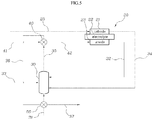
- FIG. 3 An embodiment of FIG. 3 is the same as the embodiment of FIG. 1 in that the BOG discharged from the burner 30 is firstly heat-exchanged in the high-temperature heat exchanger 40 and subsequently supplied to the recovery heat exchanger 50 installed at the burner air supply line 33 to preheat air supplied from the outside of the hot box to the burner 30.
- the embodiment of FIG. 1 in which only one recovery heat exchanger 50 is provided, the embodiment of FIG.
- 3 is different in that two recovery heat exchangers, i.e., a first recovery heat exchanger 50a and a second recovery heat exchanger 50b, are installed and the high-temperature heat exchanger passage gas having a high temperature is supplied through a high-temperature heat exchanger passage gas first branch line 36a and a high-temperature heat exchanger passage gas second branch line 36b.
- two recovery heat exchangers i.e., a first recovery heat exchanger 50a and a second recovery heat exchanger 50b
- FIG. 4 An embodiment of FIG. 4 is the same as the embodiment of FIG. 2 in that the BOG discharged from the burner 30 is directly branched to the BOG branch line 35a from the BOG supply line 35 and directly supplied to the recovery heat exchanger installed at the burner air supply line 33, without passing through the high-temperature heat exchanger 40.
- the embodiment of FIG. 4 is different in that two recovery heat exchangers, i.e., the first recovery heat exchanger 50a and the second recovery heat exchanger 50b, are installed and the high-temperature BOG is supplied through a BOG first branch line 35b and a BOG second branch line 35c.
- heat exchange may take place sufficiently between the BOG and the ambient air through heat exchange twice, and if necessary, three or more recovery heat exchangers may be installed as mentioned above with reference to FIG. 3 .
- Reference numerals 37b and 37c denote a recovery heat exchanger passage gas first discharge line and a recovery heat exchanger passage gas second discharge line, respectively.
- FIGS. 5 to 8 illustrate an embodiment in which a heat exchanger using a BOG is provided at the burner fuel gas supply line 31.
- the recovery heat exchanger 50 is disposed in the hot box, is installed at the burner fuel gas supply line 31 supplying a fuel gas to the burner 30 from the outside of the hot box, and is configured to preheat a room-temperature fuel gas supplied to the burner 30 through the burner fuel gas supply line 31 using the high-temperature BOG.
- the high-temperature BOG is firstly supplied to the high-temperature heat exchanger 40 through the BOG supply line 35.
- the high-temperature BOG is heat-exchanged with the fuel gas supplied through the high-temperature heat exchanger fuel gas supply line 41 to produce an anode gas including a high-temperature hydrogen gas.
- the BOG is generated as a high-temperature heat exchanger passage gas having a temperature lowered through the heat exchange, and the high-temperature heat exchanger passage gas is supplied to the recovery heat exchanger 50 through the high-temperature heat exchanger passage gas supply line 36.
- the high-temperature heat-exchange passage gas is slightly lowered in temperature through the first heat exchange at the high-temperature heat exchanger 40 but still maintained at a high temperature of 400°C or higher.
- the high-temperature heat-exchange passage gas having such a high temperature preheats the room-temperature fuel gas supplied from the outside of the hot box in the recovery heat exchanger 50.
- the preheated fuel gas increases an internal temperature of the burner 30 to reduce usage of fuel.
- the gas having a temperature lowered through the heat exchange is finally discharged to the outside of the hot box through the recovery heat exchanger passage gas discharge line 37.
- all of the BOG, the high-temperature heat exchanger passage gas, and the recovery heat exchanger passage gas refer to the BOG as described above. Therefore, the present embodiment may also be included in the technical concept of the present disclosure in which the fluid introduced to the burner is preheated using the heat exchanger using the BOG.
- An embodiment of FIG. 6 is basically the same as the embodiment of FIG. 5 in that the BOG discharged from the burner 30 is supplied to the recovery heat exchanger 50 installed at the burner fuel gas supply line 31 to preheat the room-temperature fuel gas supplied from the outside of the hot box to the burner 30.
- the embodiment of FIG. 6 is different in that the BOG is directly supplied to the recovery heat exchanger 50 through the BOG branch line 35a branched from the BOG supply line 35 so that heat exchange firstly take place in the recovery heat exchanger 50.
- the fuel gas may be heated to a higher temperature.
- the present embodiment may be used for a case where an external fuel gas supplied through the burner fuel gas supply line 31 is required to have a higher amount of heat in consideration of a total amount of heat of the fuel gas and air supplied to the burner 30.
- the fuel cell system may be configured by one of the embodiment of FIG. 5 (for low temperature) or the embodiment of FIG. 6 (for high temperature) in consideration of that to which temperature the external fuel gas is to be preheated, whereby an operating range of the burner 30 may be more effectively controlled.
- FIGS. 5 and 6 are disclosed as separate embodiments, it may also be configured such that the high-temperature heat exchanger passage supply line 36 of FIG. 5 and the BOG branch line 35a of FIG. 6 may be installed together in one fuel cell system and one of the two supply lines may be selectively used using a three-way valve, or the like, in real time.
- FIG. 7 An embodiment of FIG. 7 is the same as the embodiment of FIG. 5 in that the BOG discharged from the burner 30 is firstly heat-exchanged in the high-temperature heat exchanger 40 and subsequently supplied to the recovery heat exchanger 50 installed at the burner fuel gas supply line 31 to preheat the fuel gas supplied from the outside of the hot box to the burner 30.
- the embodiment of FIG. 5 in which only one recovery heat exchanger 50 is provided, the embodiment of FIG.
- the 7 is different in that two recovery heat exchangers, i.e., the first recovery heat exchanger 50a and the second recovery heat exchanger 50b, are installed and the high-temperature heat exchanger passage gas having a high temperature is supplied through the high-temperature heat exchanger passage gas first branch line 36a and the high-temperature heat exchanger passage gas second branch line 36b.
- FIG. 8 An embodiment of FIG. 8 is the same as the embodiment of FIG. 6 in that the BOG discharged from the burner 30 is directly branched to the BOG branch line 35a from the BOG supply line 35 and directly supplied to the recovery heat exchanger installed at the burner fuel gas supply line 31, without passing through the high-temperature heat exchanger 40.
- the embodiment of FIG. 8 is different in that two recovery heat exchangers, i.e., the first recovery heat exchanger 50a and the second recovery heat exchanger 50b, are installed and the high-temperature BOG is supplied through the BOG first branch line 35b and the BOG second branch line 35c.
- heat exchange may take place sufficiently between the BOG and the external fuel gas through heat exchange twice, and if necessary, three or more recovery heat exchangers may be installed as mentioned above with reference to FIG. 7 .
- Reference numerals 37b and 37c denote the recovery heat exchanger passage gas first discharge line and the recovery heat exchanger passage gas second discharge line, respectively.
- FIGS. 9 to 12 illustrate an embodiment in which a heat exchanger using a BOG is installed at the burner anode off-gas (AOG) supply line 32.
- AOG burner anode off-gas
- the recovery heat exchanger 50 is disposed in the hot box, is installed at the burner AOG supply line 32 supplying the AOG containing unburned hydrogen to the burner 30 from the outside of the hot box, and is configured to preheat the AOG supplied to the burner 30 through the burner AOG supply line 32 using the high-temperature BOG.
- the AOG Since the AOG itself is very hot, the AOG is subjected to a heat recovery step through heat exchange several times. Typically, the AOG is heat-exchanged with hot water, while passing through a heat storage tank (not shown) installed in the fuel cell system. The hot water is used for heating, or the like, in a household. Also, the AOG contains moisture in a vapor state generated during a chemical reaction in the fuel cell stack 20. Thus, in order to supply the AOG to the burner 30 and re-use the unreacted hydrogen, the vapor included in the AOG is required to be removed. To this end, vapor of AOG is discharged, while passing through a condenser (not shown) installed in the fuel cell system, and in this process, heat exchange takes place to lower temperature.
- a condenser not shown
- the AOG is heat exchanged in the process of passing through the heat storage tank for supplying hot water, or the like, or the condenser for separately discharging vapor contained in the AOG, and is generally supplied at a temperature of about 70°C to the burner 30.
- the 70°C-AOG is preheated using the BOG of 400°C or higher in the recovery heat exchanger 50.
- the high-temperature BOG is firstly supplied to the high-temperature heat exchanger 40 through the BOG supply line 35.
- the high-temperature BOG is heat-exchanged with a fuel gas supplied through the high-temperature heat exchanger fuel gas supply line 41 to produce an anode gas containing a high-temperature hydrogen gas.
- the BOG is generated as a high-temperature heat exchanger passage gas having a temperature lowered through the heat exchange, and the high-temperature heat-exchange passage gas is supplied to the recovery heat exchanger 50 according to the present disclosure through a high-temperature heat exchanger passage gas supply line 36.
- the high-temperature heat-exchange passage gas is slightly lowered in temperature through the first heat exchange at the high-temperature heat exchanger 40 but still maintained at a high temperature of 400°C or higher.
- the high-temperature heat-exchange passage gas having such a high temperature preheats the AOG supplied from the outside of the hot box in the recovery heat exchanger 50.
- the preheated AOG increases an internal temperature of the burner 30 to reduce usage of fuel.
- the gas having a temperature lowered through the heat exchange is finally discharged to the outside of the hot box through a recovery heat exchanger passage gas discharge line 37.
- all of the BOG, the high-temperature heat exchanger passage gas, and the recovery heat exchanger passage gas refer to the BOG as described above. Therefore, the present embodiment may also be included in the technical concept of the present disclosure in which the fluid introduced to the burner is preheated using the heat exchanger using the BOG.
- An embodiment of FIG. 10 is basically the same as the embodiment of FIG. 9 in that the BOG discharged from the burner 30 is supplied to the recovery heat exchanger 50 installed at the burner AOG supply line 32 to preheat the AOG supplied from the outside of the hot box to the burner 30.
- the embodiment of FIG. 10 is different in that the BOG is directly supplied to the recovery heat exchanger 50 through the BOG branch line 35a branched from the BOG supply line 35 so that heat exchange firstly take place in the recovery heat exchanger 50.
- the present embodiment may be used for a case where an external fuel gas supplied through the burner AOG supply line 32 is required to have a higher amount of heat in consideration of a total amount of heat of the fuel gas and air supplied to the burner 30.
- the fuel cell system may be configured by one of the embodiment of FIG. 9 (for low temperature) or the embodiment of FIG. 10 (for high temperature) in consideration of that to which temperature the external fuel gas is to be preheated, whereby an operating range of the burner 30 may be more effectively controlled.
- FIGS. 9 and 10 are disclosed as separate embodiments, it may also be configured such that the high-temperature heat exchanger passage supply line 36 of FIG. 9 and the BOG branch line 35a of FIG. 10 may be installed together in one fuel cell system and one of the two supply lines may be selectively used using a three-way valve, or the like, in real time.
- FIG. 11 An embodiment of FIG. 11 is the same as the embodiment of FIG. 9 in that the BOG discharged from the burner 30 is firstly heat-exchanged in the high-temperature heat exchanger 40 and subsequently supplied to the recovery heat exchanger 50 installed at the burner AOG supply line 32 to preheat the fuel gas supplied from the outside of the hot box to the burner 30.
- the embodiment of FIG. 9 in which only one recovery heat exchanger 50 is provided, the embodiment of FIG.
- 11 is different in that two recovery heat exchangers, i.e., the first recovery heat exchanger 50a and the second recovery heat exchanger 50b, are installed and the high-temperature heat exchanger passage gas having a high temperature is supplied through the high-temperature heat exchanger passage gas first branch line 36a and the high-temperature heat exchanger passage gas second branch line 36b.
- FIG. 12 An embodiment of FIG. 12 is the same as the embodiment of FIG. 10 in that the BOG discharged from the burner 30 is directly branched to the BOG branch line 35a from the BOG supply line 35 and directly supplied to the recovery heat exchanger installed at the burner AOG supply line 32, without passing through the high-temperature heat exchanger 40.
- the embodiment of FIG. 12 is different in that two recovery heat exchangers, i.e., the first recovery heat exchanger 50a and the second recovery heat exchanger 50b, are installed and the high-temperature BOG is supplied through the BOG first branch line 35b and the BOG second branch line 35c.
- heat exchange may take place sufficiently between the BOG and the external fuel gas through heat exchange twice, and if necessary, three or more recovery heat exchangers may be installed as mentioned above with reference to FIG. 11 .
- Reference numerals 37b and 37c denote the recovery heat exchanger passage gas first discharge line and the recovery heat exchanger passage gas second discharge line, respectively.
- preheating ambient air supplied through the burner air supply line 33 as illustrated in FIG. 1 and preheating the fuel gas supplied through the burner fuel gas supply line 31 as illustrated in FIG. 5 or preheating the AOG supplied through the burner AOG supply line 32 as illustrated in FIG. 9 may be different in heat exchange efficiency due to a difference in flow rate between the supply lines. Based on this, utilization of the BOG finally discharged to the outside of the hot box may be designed to be different.
- a supply flow rate of the BOG supply line 35 is the largest
- a supply flow rate of the burner air supply line 33 is the second largest
- a supply flow rate of the burner fuel gas supply line 31 and the burner AOG supply line 32 is relatively very small.
- Heat exchange sufficiently takes place between the BOG and the ambient air which are not significantly different in supply flow rate, so a temperature of the finally discharged recovery heat exchanger passage gas is low. As a result, efficiency of heat exchange in the heat storage tank at a follow-up stage is relatively reduced. Meanwhile, heat exchange does not sufficiently take place between the BOG and the fuel gas (or AOG) which are significantly different in supply flow rate, so the temperature of the finally discharged recovery heat exchanger passage gas is high. As a result, efficiency of heat exchange in the heat storage tank at the follow-up stage is relatively increased. Since the fuel cell system is a system capable of simultaneously generating electricity and heat, whether to preheat air or whether to preheat the fuel gas (or AOG) may be selected among the various embodiments of the present disclosure in consideration of efficiency of heat recovery at the heat storage tank.
Landscapes
- Chemical & Material Sciences (AREA)
- Engineering & Computer Science (AREA)
- Life Sciences & Earth Sciences (AREA)
- Manufacturing & Machinery (AREA)
- Sustainable Development (AREA)
- Sustainable Energy (AREA)
- Chemical Kinetics & Catalysis (AREA)
- Electrochemistry (AREA)
- General Chemical & Material Sciences (AREA)
- Combustion & Propulsion (AREA)
- Fuel Cell (AREA)
Applications Claiming Priority (2)
| Application Number | Priority Date | Filing Date | Title |
|---|---|---|---|
| KR1020160078436A KR101897486B1 (ko) | 2016-06-23 | 2016-06-23 | 연소 배가스를 이용한 열교환기를 포함하는 연료전지 시스템 |
| PCT/KR2017/006434 WO2017222267A1 (ko) | 2016-06-23 | 2017-06-20 | 연소 배가스를 이용한 열교환기를 포함하는 연료전지 시스템 |
Publications (2)
| Publication Number | Publication Date |
|---|---|
| EP3477752A1 true EP3477752A1 (de) | 2019-05-01 |
| EP3477752A4 EP3477752A4 (de) | 2019-08-14 |
Family
ID=60784889
Family Applications (1)
| Application Number | Title | Priority Date | Filing Date |
|---|---|---|---|
| EP17815680.8A Withdrawn EP3477752A4 (de) | 2016-06-23 | 2017-06-20 | Brennstoffzellensystem mit wärmetauscher mit verbrennungsabgas |
Country Status (4)
| Country | Link |
|---|---|
| US (1) | US20190148743A1 (de) |
| EP (1) | EP3477752A4 (de) |
| KR (1) | KR101897486B1 (de) |
| WO (1) | WO2017222267A1 (de) |
Cited By (1)
| Publication number | Priority date | Publication date | Assignee | Title |
|---|---|---|---|---|
| GB2621338A (en) * | 2022-08-08 | 2024-02-14 | Ceres Ip Co Ltd | Fuel cell system and method of operating the same |
Families Citing this family (2)
| Publication number | Priority date | Publication date | Assignee | Title |
|---|---|---|---|---|
| CN114447367B (zh) * | 2021-12-31 | 2024-04-19 | 武汉科技大学 | 一种集成化热工部件、发电系统及固体氧化物燃料电池 |
| CN114361513B (zh) * | 2022-01-13 | 2024-04-16 | 潍柴动力股份有限公司 | 一种氢燃料电池发动机加热氢气的系统和方法 |
Family Cites Families (14)
| Publication number | Priority date | Publication date | Assignee | Title |
|---|---|---|---|---|
| US4128700A (en) * | 1977-11-26 | 1978-12-05 | United Technologies Corp. | Fuel cell power plant and method for operating the same |
| JP3614110B2 (ja) * | 2001-02-21 | 2005-01-26 | 日産自動車株式会社 | 燃料電池システム |
| US20050019626A1 (en) * | 2003-07-21 | 2005-01-27 | Burch Steven D. | High-efficiency fuel processor via steam integration from a water-cooled stack |
| US7964176B2 (en) * | 2005-03-29 | 2011-06-21 | Chevron U.S.A. Inc. | Process and apparatus for thermally integrated hydrogen generation system |
| JP4981281B2 (ja) * | 2005-08-29 | 2012-07-18 | 電源開発株式会社 | 燃料電池システムおよび燃料電池システムの制御方法 |
| GB2450042B (en) * | 2006-03-24 | 2012-02-01 | Ceres Ip Co Ltd | Fuel cell stack system assembly |
| JP2009099437A (ja) * | 2007-10-18 | 2009-05-07 | Honda Motor Co Ltd | 燃料電池モジュール |
| KR101009453B1 (ko) * | 2008-01-15 | 2011-01-19 | 한국전력공사 | 열적 자립운전이 가능한 고체 산화물 연료전지 시스템 |
| JP2009205868A (ja) * | 2008-02-26 | 2009-09-10 | Think Tank Phoenix:Kk | 固体電解質燃料電池システムおよび固体電解質燃料電池 |
| KR100987823B1 (ko) | 2009-01-12 | 2010-10-18 | 한국과학기술원 | 고체산화물 연료전지 시스템 |
| KR101259820B1 (ko) * | 2011-01-14 | 2013-04-30 | 삼성중공업 주식회사 | 연료전지시스템 및 이를 구비한 선박 |
| KR20130030998A (ko) * | 2011-09-20 | 2013-03-28 | 에스티엑스중공업 주식회사 | 촉매 연소기를 구비하는 가정용 연료전지 보일러 시스템 |
| KR101363365B1 (ko) * | 2012-06-04 | 2014-02-17 | 주식회사 경동나비엔 | 연료전지 시스템 |
| GB201312329D0 (en) * | 2013-07-09 | 2013-08-21 | Ceres Ip Co Ltd | Improved fuel cell systems and methods |
-
2016
- 2016-06-23 KR KR1020160078436A patent/KR101897486B1/ko active IP Right Grant
-
2017
- 2017-06-20 WO PCT/KR2017/006434 patent/WO2017222267A1/ko unknown
- 2017-06-20 EP EP17815680.8A patent/EP3477752A4/de not_active Withdrawn
- 2017-06-20 US US16/313,379 patent/US20190148743A1/en not_active Abandoned
Cited By (1)
| Publication number | Priority date | Publication date | Assignee | Title |
|---|---|---|---|---|
| GB2621338A (en) * | 2022-08-08 | 2024-02-14 | Ceres Ip Co Ltd | Fuel cell system and method of operating the same |
Also Published As
| Publication number | Publication date |
|---|---|
| KR101897486B1 (ko) | 2018-09-12 |
| US20190148743A1 (en) | 2019-05-16 |
| WO2017222267A1 (ko) | 2017-12-28 |
| EP3477752A4 (de) | 2019-08-14 |
| KR20180000451A (ko) | 2018-01-03 |
Similar Documents
| Publication | Publication Date | Title |
|---|---|---|
| WO2013100490A1 (ko) | 연료전지 하이브리드 시스템 | |
| CN100573995C (zh) | 燃料电池设备内的预热装置 | |
| US10381665B2 (en) | Device and method for heating fuel cell stack and fuel cell system having the device | |
| EP3477751A1 (de) | Brennstoffzellensystem mit wärmetauscher unter verwendung von anodengas oder anodenabgas | |
| EP3477752A1 (de) | Brennstoffzellensystem mit wärmetauscher mit verbrennungsabgas | |
| US8445155B2 (en) | Complex power generation system and method for supplying heated water thereof | |
| JP2008234994A (ja) | 燃料電池システム | |
| EP2858158B1 (de) | Brennstoffzellensystem | |
| US20180191006A1 (en) | Solid oxide fuel cell system with improved thermal efficiency, and solid oxide fuel cell system heated by high-temperature gas | |
| KR20170002143A (ko) | 외부열원에 의하여 가열되는 고체산화물 연료전지 시스템 | |
| EP2886964B1 (de) | Kombiniertes brennstoffzellen- und kesselsystem | |
| JPH07230819A (ja) | 自己熱交換型断熱プレリフォーマを有する内部改質型固体電解質燃料電池システム | |
| JP4590872B2 (ja) | 燃料電池発電装置の運転方法 | |
| KR101439671B1 (ko) | 가열통합형 연료전지 모듈 | |
| CN114586205B (zh) | 混合发电系统 | |
| JPH06103994A (ja) | 燃料電池発電システム | |
| KR101771501B1 (ko) | 연료전지시스템용 가습장치 | |
| WO2023126625A1 (en) | Fuel cell system | |
| KR20170002144A (ko) | 코팅층이 형성된 고체산화물 연료전지 시스템 | |
| GB2614325A (en) | Fuel cell system | |
| KR101324112B1 (ko) | 연료전지 시스템 | |
| KR20170129428A (ko) | 연료전지시스템용 가습장치 | |
| EP3163660A1 (de) | Brennstoffzellenmodul mit erhöhter wärmeeffizienz und heizsystem damit sowie steuerungsverfahren dafür |
Legal Events
| Date | Code | Title | Description |
|---|---|---|---|
| STAA | Information on the status of an ep patent application or granted ep patent |
Free format text: STATUS: THE INTERNATIONAL PUBLICATION HAS BEEN MADE |
|
| PUAI | Public reference made under article 153(3) epc to a published international application that has entered the european phase |
Free format text: ORIGINAL CODE: 0009012 |
|
| STAA | Information on the status of an ep patent application or granted ep patent |
Free format text: STATUS: REQUEST FOR EXAMINATION WAS MADE |
|
| 17P | Request for examination filed |
Effective date: 20190103 |
|
| AK | Designated contracting states |
Kind code of ref document: A1 Designated state(s): AL AT BE BG CH CY CZ DE DK EE ES FI FR GB GR HR HU IE IS IT LI LT LU LV MC MK MT NL NO PL PT RO RS SE SI SK SM TR |
|
| AX | Request for extension of the european patent |
Extension state: BA ME |
|
| RIC1 | Information provided on ipc code assigned before grant |
Ipc: H01M 8/124 20160101ALN20190412BHEP Ipc: H01M 8/0612 20160101ALN20190412BHEP Ipc: H01M 8/04014 20160101AFI20190412BHEP Ipc: H01M 8/2475 20160101ALN20190412BHEP |
|
| A4 | Supplementary search report drawn up and despatched |
Effective date: 20190715 |
|
| RIC1 | Information provided on ipc code assigned before grant |
Ipc: H01M 8/04014 20160101AFI20190709BHEP Ipc: H01M 8/124 20160101ALN20190709BHEP Ipc: H01M 8/2475 20160101ALI20190709BHEP Ipc: H01M 8/0612 20160101ALN20190709BHEP |
|
| DAV | Request for validation of the european patent (deleted) | ||
| DAX | Request for extension of the european patent (deleted) | ||
| STAA | Information on the status of an ep patent application or granted ep patent |
Free format text: STATUS: THE APPLICATION IS DEEMED TO BE WITHDRAWN |
|
| 18D | Application deemed to be withdrawn |
Effective date: 20200212 |