EP3477334A1 - Étalonnage de détecteur radar automatique - Google Patents
Étalonnage de détecteur radar automatique Download PDFInfo
- Publication number
- EP3477334A1 EP3477334A1 EP17197920.6A EP17197920A EP3477334A1 EP 3477334 A1 EP3477334 A1 EP 3477334A1 EP 17197920 A EP17197920 A EP 17197920A EP 3477334 A1 EP3477334 A1 EP 3477334A1
- Authority
- EP
- European Patent Office
- Prior art keywords
- calibration
- output signals
- radar
- sensor output
- calibration object
- Prior art date
- Legal status (The legal status is an assumption and is not a legal conclusion. Google has not performed a legal analysis and makes no representation as to the accuracy of the status listed.)
- Ceased
Links
- 238000000034 method Methods 0.000 claims abstract description 90
- 238000012545 processing Methods 0.000 claims abstract description 37
- 238000001514 detection method Methods 0.000 claims abstract description 34
- 238000012512 characterization method Methods 0.000 claims description 3
- 238000003860 storage Methods 0.000 description 8
- 230000004927 fusion Effects 0.000 description 6
- 238000013459 approach Methods 0.000 description 4
- 230000005540 biological transmission Effects 0.000 description 4
- 238000010586 diagram Methods 0.000 description 4
- 230000000694 effects Effects 0.000 description 4
- 238000004891 communication Methods 0.000 description 3
- 238000005457 optimization Methods 0.000 description 3
- 238000007781 pre-processing Methods 0.000 description 3
- 238000004590 computer program Methods 0.000 description 2
- 238000012937 correction Methods 0.000 description 2
- 238000013461 design Methods 0.000 description 2
- 238000001914 filtration Methods 0.000 description 2
- 239000000463 material Substances 0.000 description 2
- 238000005259 measurement Methods 0.000 description 2
- 239000002245 particle Substances 0.000 description 2
- 230000008054 signal transmission Effects 0.000 description 2
- 230000032683 aging Effects 0.000 description 1
- 238000003491 array Methods 0.000 description 1
- 230000003247 decreasing effect Effects 0.000 description 1
- 238000009826 distribution Methods 0.000 description 1
- 230000006870 function Effects 0.000 description 1
- 230000010354 integration Effects 0.000 description 1
- 238000004519 manufacturing process Methods 0.000 description 1
- 230000003287 optical effect Effects 0.000 description 1
- 230000002085 persistent effect Effects 0.000 description 1
- 230000010363 phase shift Effects 0.000 description 1
- 230000002265 prevention Effects 0.000 description 1
- 239000007787 solid Substances 0.000 description 1
- 230000001629 suppression Effects 0.000 description 1
- 238000012360 testing method Methods 0.000 description 1
Images


Classifications
-
- G—PHYSICS
- G01—MEASURING; TESTING
- G01S—RADIO DIRECTION-FINDING; RADIO NAVIGATION; DETERMINING DISTANCE OR VELOCITY BY USE OF RADIO WAVES; LOCATING OR PRESENCE-DETECTING BY USE OF THE REFLECTION OR RERADIATION OF RADIO WAVES; ANALOGOUS ARRANGEMENTS USING OTHER WAVES
- G01S7/00—Details of systems according to groups G01S13/00, G01S15/00, G01S17/00
- G01S7/02—Details of systems according to groups G01S13/00, G01S15/00, G01S17/00 of systems according to group G01S13/00
- G01S7/40—Means for monitoring or calibrating
- G01S7/4004—Means for monitoring or calibrating of parts of a radar system
-
- G—PHYSICS
- G01—MEASURING; TESTING
- G01S—RADIO DIRECTION-FINDING; RADIO NAVIGATION; DETERMINING DISTANCE OR VELOCITY BY USE OF RADIO WAVES; LOCATING OR PRESENCE-DETECTING BY USE OF THE REFLECTION OR RERADIATION OF RADIO WAVES; ANALOGOUS ARRANGEMENTS USING OTHER WAVES
- G01S13/00—Systems using the reflection or reradiation of radio waves, e.g. radar systems; Analogous systems using reflection or reradiation of waves whose nature or wavelength is irrelevant or unspecified
- G01S13/02—Systems using reflection of radio waves, e.g. primary radar systems; Analogous systems
- G01S13/06—Systems determining position data of a target
- G01S13/42—Simultaneous measurement of distance and other co-ordinates
- G01S13/44—Monopulse radar, i.e. simultaneous lobing
- G01S13/4454—Monopulse radar, i.e. simultaneous lobing phase comparisons monopulse, i.e. comparing the echo signals received by an interferometric antenna arrangement
-
- G—PHYSICS
- G01—MEASURING; TESTING
- G01S—RADIO DIRECTION-FINDING; RADIO NAVIGATION; DETERMINING DISTANCE OR VELOCITY BY USE OF RADIO WAVES; LOCATING OR PRESENCE-DETECTING BY USE OF THE REFLECTION OR RERADIATION OF RADIO WAVES; ANALOGOUS ARRANGEMENTS USING OTHER WAVES
- G01S13/00—Systems using the reflection or reradiation of radio waves, e.g. radar systems; Analogous systems using reflection or reradiation of waves whose nature or wavelength is irrelevant or unspecified
- G01S13/74—Systems using reradiation of radio waves, e.g. secondary radar systems; Analogous systems
-
- G—PHYSICS
- G01—MEASURING; TESTING
- G01S—RADIO DIRECTION-FINDING; RADIO NAVIGATION; DETERMINING DISTANCE OR VELOCITY BY USE OF RADIO WAVES; LOCATING OR PRESENCE-DETECTING BY USE OF THE REFLECTION OR RERADIATION OF RADIO WAVES; ANALOGOUS ARRANGEMENTS USING OTHER WAVES
- G01S13/00—Systems using the reflection or reradiation of radio waves, e.g. radar systems; Analogous systems using reflection or reradiation of waves whose nature or wavelength is irrelevant or unspecified
- G01S13/87—Combinations of radar systems, e.g. primary radar and secondary radar
- G01S13/878—Combination of several spaced transmitters or receivers of known location for determining the position of a transponder or a reflector
-
- G—PHYSICS
- G01—MEASURING; TESTING
- G01S—RADIO DIRECTION-FINDING; RADIO NAVIGATION; DETERMINING DISTANCE OR VELOCITY BY USE OF RADIO WAVES; LOCATING OR PRESENCE-DETECTING BY USE OF THE REFLECTION OR RERADIATION OF RADIO WAVES; ANALOGOUS ARRANGEMENTS USING OTHER WAVES
- G01S13/00—Systems using the reflection or reradiation of radio waves, e.g. radar systems; Analogous systems using reflection or reradiation of waves whose nature or wavelength is irrelevant or unspecified
- G01S13/88—Radar or analogous systems specially adapted for specific applications
- G01S13/93—Radar or analogous systems specially adapted for specific applications for anti-collision purposes
- G01S13/931—Radar or analogous systems specially adapted for specific applications for anti-collision purposes of land vehicles
-
- G—PHYSICS
- G01—MEASURING; TESTING
- G01S—RADIO DIRECTION-FINDING; RADIO NAVIGATION; DETERMINING DISTANCE OR VELOCITY BY USE OF RADIO WAVES; LOCATING OR PRESENCE-DETECTING BY USE OF THE REFLECTION OR RERADIATION OF RADIO WAVES; ANALOGOUS ARRANGEMENTS USING OTHER WAVES
- G01S7/00—Details of systems according to groups G01S13/00, G01S15/00, G01S17/00
- G01S7/02—Details of systems according to groups G01S13/00, G01S15/00, G01S17/00 of systems according to group G01S13/00
- G01S7/40—Means for monitoring or calibrating
- G01S7/4004—Means for monitoring or calibrating of parts of a radar system
- G01S7/4021—Means for monitoring or calibrating of parts of a radar system of receivers
-
- G—PHYSICS
- G01—MEASURING; TESTING
- G01S—RADIO DIRECTION-FINDING; RADIO NAVIGATION; DETERMINING DISTANCE OR VELOCITY BY USE OF RADIO WAVES; LOCATING OR PRESENCE-DETECTING BY USE OF THE REFLECTION OR RERADIATION OF RADIO WAVES; ANALOGOUS ARRANGEMENTS USING OTHER WAVES
- G01S7/00—Details of systems according to groups G01S13/00, G01S15/00, G01S17/00
- G01S7/02—Details of systems according to groups G01S13/00, G01S15/00, G01S17/00 of systems according to group G01S13/00
- G01S7/40—Means for monitoring or calibrating
- G01S7/4004—Means for monitoring or calibrating of parts of a radar system
- G01S7/4026—Antenna boresight
-
- G—PHYSICS
- G01—MEASURING; TESTING
- G01S—RADIO DIRECTION-FINDING; RADIO NAVIGATION; DETERMINING DISTANCE OR VELOCITY BY USE OF RADIO WAVES; LOCATING OR PRESENCE-DETECTING BY USE OF THE REFLECTION OR RERADIATION OF RADIO WAVES; ANALOGOUS ARRANGEMENTS USING OTHER WAVES
- G01S13/00—Systems using the reflection or reradiation of radio waves, e.g. radar systems; Analogous systems using reflection or reradiation of waves whose nature or wavelength is irrelevant or unspecified
- G01S13/02—Systems using reflection of radio waves, e.g. primary radar systems; Analogous systems
- G01S2013/0236—Special technical features
- G01S2013/0245—Radar with phased array antenna
- G01S2013/0263—Passive array antenna
-
- G—PHYSICS
- G01—MEASURING; TESTING
- G01S—RADIO DIRECTION-FINDING; RADIO NAVIGATION; DETERMINING DISTANCE OR VELOCITY BY USE OF RADIO WAVES; LOCATING OR PRESENCE-DETECTING BY USE OF THE REFLECTION OR RERADIATION OF RADIO WAVES; ANALOGOUS ARRANGEMENTS USING OTHER WAVES
- G01S3/00—Direction-finders for determining the direction from which infrasonic, sonic, ultrasonic, or electromagnetic waves, or particle emission, not having a directional significance, are being received
- G01S3/02—Direction-finders for determining the direction from which infrasonic, sonic, ultrasonic, or electromagnetic waves, or particle emission, not having a directional significance, are being received using radio waves
- G01S3/023—Monitoring or calibrating
-
- G—PHYSICS
- G01—MEASURING; TESTING
- G01S—RADIO DIRECTION-FINDING; RADIO NAVIGATION; DETERMINING DISTANCE OR VELOCITY BY USE OF RADIO WAVES; LOCATING OR PRESENCE-DETECTING BY USE OF THE REFLECTION OR RERADIATION OF RADIO WAVES; ANALOGOUS ARRANGEMENTS USING OTHER WAVES
- G01S7/00—Details of systems according to groups G01S13/00, G01S15/00, G01S17/00
- G01S7/02—Details of systems according to groups G01S13/00, G01S15/00, G01S17/00 of systems according to group G01S13/00
- G01S7/40—Means for monitoring or calibrating
- G01S7/4052—Means for monitoring or calibrating by simulation of echoes
- G01S7/4082—Means for monitoring or calibrating by simulation of echoes using externally generated reference signals, e.g. via remote reflector or transponder
- G01S7/4086—Means for monitoring or calibrating by simulation of echoes using externally generated reference signals, e.g. via remote reflector or transponder in a calibrating environment, e.g. anechoic chamber
-
- G—PHYSICS
- G01—MEASURING; TESTING
- G01S—RADIO DIRECTION-FINDING; RADIO NAVIGATION; DETERMINING DISTANCE OR VELOCITY BY USE OF RADIO WAVES; LOCATING OR PRESENCE-DETECTING BY USE OF THE REFLECTION OR RERADIATION OF RADIO WAVES; ANALOGOUS ARRANGEMENTS USING OTHER WAVES
- G01S7/00—Details of systems according to groups G01S13/00, G01S15/00, G01S17/00
- G01S7/02—Details of systems according to groups G01S13/00, G01S15/00, G01S17/00 of systems according to group G01S13/00
- G01S7/40—Means for monitoring or calibrating
- G01S7/4052—Means for monitoring or calibrating by simulation of echoes
- G01S7/4082—Means for monitoring or calibrating by simulation of echoes using externally generated reference signals, e.g. via remote reflector or transponder
- G01S7/4095—Means for monitoring or calibrating by simulation of echoes using externally generated reference signals, e.g. via remote reflector or transponder the external reference signals being modulated, e.g. rotating a dihedral reflector or modulating a transponder for simulation of a Doppler echo
Definitions
- the present disclosure relates to methods and devices for calibrating a radar sensor system, such as a radar sensor system for use in vehicular applications.
- vehicle environment sensor systems such as camera systems, radio detection and ranging (radar) systems and light detection and ranging (lidar) systems
- radar radio detection and ranging
- lidar light detection and ranging
- the input from these sensor systems can be used to automate vehicle systems such as speed control and collision prevention.
- Auto alignment, ego motion estimation, scene understanding, lane keeping assist (LKA) and automated driving (AD) are also enabled by using the sensor system output signals.
- Radar systems are sensor systems arranged to produce output comprising a series of reflection points as measured by radar receiver sensors. Reflection points can be treated as separate detections or grouped if they relate to the same object. Reflection points or groups of reflection points observed over time can be used to track the motion of an object over time. Such a determination over time is referred to as the track of an object.
- Radar sensors used to estimate bearings are affected by various vehicle components such as different types of bumpers and vehicle front and rear section geometries. Sensors are also affected by variations during manufacturing and assembly. Sensor systems therefore require calibration to produce accurate sensor output signals. This calibration is often performed in factory, which is time-consuming and drives cost. Optimal calibration parameters may also change over time, which necessitates a re-calibration, which may not be convenient.
- US 6,778,928 B2 discloses a method for calibrating a camera-based sensor system. This method uses stationary objects in the path of a vehicle to calibrate sensor systems comprising a camera-based sensor device.
- This object is achieved by a method performed by a sensor signal processing unit for calibrating output signals from radar sensors.
- the method comprises selecting a calibration object located in a field of view of the radar sensors, and generating expected sensor output signals corresponding to detection of the calibration object based on a model of the calibration object.
- the method also comprises receiving sensor output signals from the radar sensors associated with detection of the calibration object, and updating a calibration parameter of the radar sensors based on a comparison between the expected sensor output signals and the received sensor output signals, wherein the updated calibration parameters comprise calibration information for calibrating a value of the radar sensor output signals.
- a raw sensor output signal is automatically calibrated before it has been used to determine other more high-level quantities, such as bearing or location. Furthermore, said calibration requires no permanent calibration equipment or in-factory calibration, and can be run continuously during normal operation of the sensor system.
- sensor systems do not require extensive calibration performed in factory, which saves time and reduces overall cost.
- Re-calibration is conveniently performed during normal operation of the sensor system, which voids inconvenient sensor re-calibration.
- US 6,778,928 B2 uses a camera-based sensor system in conjunction with a radar-based sensor system to jointly estimate model parameters and calibrate certain high-level parameters of the total system. It is unclear exactly how the calibration is performed in 6,778,928 B2 as the disclosure appears incomplete.
- the calibrated value of the radar sensor output signals comprises any of a phase value, an amplitude value, a complex signal value, or a polar coordinate signal value.
- the method comprises initializing the calibration parameter of the radar sensors based on a type of a vehicle component arranged in a vicinity of the radar sensors.
- a known vehicle component configuration can be used to reduce calibration convergence time and to increase calibration accuracy.
- the method comprises estimating a level of stationarity of the selected calibration object, or estimating a probability that the selected calibration object corresponds to a stationary object.
- the method also comprises selecting a non-stationary object as the calibration object.
- a non-stationary object as the calibration object.
- the method can be applied in a wider variety of scenarios, even if no stationary object exists to use in the calibration procedure. This is made possible by the feature of the method only requiring generating expected sensor output signals corresponding to detection of the calibration object, based on a model of the calibration object.
- Said model may correspond to a stationary object, or to a non-stationary object such as a moving vehicle.
- the method comprises selecting an active radar signal source as the calibration object.
- the active radar signal source generates a strong received signal which is especially advantageous to use in the calibration routine.
- the sensor signal processing unit comprises a control unit arranged to select a calibration object located in a field of view of the radar sensors, and to generate expected sensor output signals corresponding to detection of the calibration object, based on a model of the calibration object.
- the control unit is also arranged to receive sensor output signals from the radar sensors associated with detection of the calibration object, and to update a calibration parameter of the radar sensors based on a comparison between the expected sensor output signals and the received sensor output signals.
- the updated calibration parameters comprise calibration information for calibrating a value of the radar sensor output signals.
- Radar-based sensor systems require calibration in order to provide accurate sensor output signals. For instance, a radar sensor system configured to measure bearing from a vehicle to an object will provide biased sensor output signals in case the radar sensor device is not correctly mounted with respect to a boresight angle of the vehicle during vehicle assembly. To correct such errors, radar sensor systems undergo calibration after vehicle assembly to compensate for any discrepancies and imperfections in sensor output signals. This calibration procedure is time consuming and drives cost.
- Calibration is the process of generating or determining the value or values of a calibration parameter associated with the radar sensor system.
- a calibration parameter may comprise any number of entries, which entries are used to adjust the output from sensor systems to provide an increased accuracy.
- a calibration parameter may comprise phase difference adjustment values to be applied to measured radar signal phase differences.
- Optimal or near-optimal calibration parameter values may change over time due to component aging, changes in sensor mounting, or other external or internal factors. In case such change over time is significant, re-calibration of sensor systems may be necessary. Such re-calibration may be costly or difficult to perform.
- US 6,778,928 B2 discloses a method of calibrating a sensor system.
- the method detects stationary or quasi-stationary objects in a vicinity of the sensor system.
- Data inferred from sensor signals, i.e., coordinates and/or bearings, are then sent to a calibration unit which compares the 'real world' data to corresponding data generated from a 'model world' comprising the detected stationary or non-stationary objects.
- This comparison between, e.g., coordinates as exemplified in US 6,778,928 B2 results in an error vector determined as a difference between modelled coordinates and coordinates estimated from sensor signals, i.e., camera imagery.
- the method attempts to minimize this error vector by some non-disclosed algorithm which adjusts model parameters and calibration parameters jointly.
- a potential drawback of the method proposed in US 6,778,928 B2 is that the calibration parameters are applied on a relatively abstract level, i.e., calibration is performed on coordinates and bearings, not on raw sensor output signals.
- a calibration method which calibrates raw radar sensor output signals directly, instead of calibrating on a higher level.
- a radar-based sensor system arranged to generate sensor output signals 151 comprising a phase and an amplitude will be calibrated directly on raw sensor output signal levels, instead of on a bearing derived from the raw sensor output signal.
- a raw sensor output signal is to be interpreted broadly and may comprise any of a complex signal, a phase signal, an amplitude signal, and a signal represented by polar coordinates.
- a raw sensor output signal is a sensor output signal which has not been post-processed into an estimate of, e.g., range, bearing, or coordinates.
- FIG. 1 is a block diagram illustrating a sensor signal processing system according to aspects of the present disclosure.
- a calibration object 130 is present in a field of view (FOV) of a radar-based sensor system 110.
- the radar-based sensor system here comprises two radar receiving antennas 111, 112.
- Sensor output signals 115 from the radar sensors are input to a control unit 101 which is arranged to apply pre-processing to the sensor output signals.
- the sensor output signals are calibrated in a pre-processing unit 150 using calibration data from a calibration parameter unit 120 before being used for other purposes, i.e., to determine bearings to objects.
- the received sensor signals, after calibration, may according to some aspects be transmitted to a sensor fusion module 170 which estimates and/or tracks objects in a vicinity of the sensor system.
- the sensor fusion module maintains an updated description of the surrounding environment, including any objects, such as the calibration object 130.
- the sensor fusion unit 170 provides calibration object data 171, to form a model 140 of the calibration object 130, which model 140 can be used to predict what the received sensor output signals should look like, given the present state of the surrounding environment and the current state of, e.g., a vehicle to which the sensor systems have been mounted.
- This sensor output prediction 141, or expected sensor output signals 141 are used in a comparison 165 with the preprocessed sensor signals 151 that were received from the sensor system. This way, expected or predicted sensor output signals are compared to what the radar-based sensor system actually measures.
- the comparison 165 may be performed on the sensor output prediction signal 141 and the sensor output signals 115 prior to pre-processing 150.
- a comparison 165 is made between expected sensor output signals 14) and received sensor output signals 115
- a comparison 165 is made between expected sensor output signals 14) and calibrated received sensor output signals 151.
- the comparison result i.e., the difference between expected and received sensor output
- This calibration update routine is arranged to select a calibration vector which minimizes the comparison result, i.e., which minimizes the difference between expected and received sensor output signal. This difference between expected and received sensor output signal will herein sometimes be referred to as an error signal.
- the minimization of the error signal can be performed by means of least-mean-squares minimization, by Kalman filtering, by particle filtering, and the like.
- the minimization of the error signal can also be performed by means of a search over a range of calibration parameter values.
- the calibration object may be stationary or non-stationary.
- the calibration object may also be an active signal source, such as a radar signal repeater or relay device, or a radar signal transmitter. Such aspects will be discussed below in connection to Figure 3 .
- the radar-based sensor system 110 may according to some aspects use a transmission scheme in which a sum and a difference signal are transmitted.
- the sum signal uses two transmitters in phase to generate a strong signal in the bore-sight direction.
- the difference signal uses two transmitters with a relative output phase difference of 180 degrees to generate a transmission zero in the bore-sight direction, but with increased side-lobe transmission power. In this case a separate calibration may be performed for each transmission scheme.
- This separate calibration is particularly advantageous in scenarios where radar signal reflections are received from a large angle compared to bore-sight and with low energy.
- the difference signal transmission mode will perform better in such scenarios, while the sum signal transmission mode will perform better in other scenarios, e.g., when radar signal reflections are received from a smaller angle compared to bore-sight.
- figure 1 illustrates a sensor signal processing unit 100 arranged to calibrate output signals 115 from radar sensors 110.
- the sensor signal processing unit 100 comprises a control unit 101 arranged to select a calibration object 130 located in a field of view of the radar sensors, and to generate expected sensor output signals 141 corresponding to detection of the calibration object 130, based on a model 140 of the calibration object 130.
- the control unit 101 is also arranged to receive sensor output signals 115 from the radar sensors 110 associated with detection of the calibration object 130, and to update a calibration parameter 120 of the radar sensors 110 based on a comparison 165 between the expected sensor output signals 141 and the received sensor output signals 151.
- the updated calibration parameters comprise calibration information for calibrating a value of the radar sensor output signals.
- the calibrated value of the radar sensor output signals 115 comprises any of a phase value, an amplitude value, a complex signal value, or a polar coordinate signal value.
- calibration of a phase value comprises comparing expected sensor output phase signals 141 corresponding to detection of the calibration object 130 to sensor output phase signals 151 from the radar sensors 110 associated with detection of the calibration object 130.
- a model of the calibration object may comprise angle information, such as a bearing, from a radar sensor to the object.
- An expected phase of received sensor output signal can then be estimated from a doppler distribution over bearing This expected phase can be compared to the actual received phase. The comparison result can then be used to update the calibration parameter.
- calibration of an amplitude value comprises comparing expected sensor output amplitude signals 141 corresponding to detection of the calibration object 130 to sensor output amplitude signals 151 from the radar sensors 110 associated with detection of the calibration object 130.
- a model of signal attenuation can be used in conjunction with a model of range between a radar sensor and the object as well as a measure of transmitted signal power in order to estimate an expected amplitude of received radar sensor signals. This expected amplitude can be compared to an actual received amplitude value. The comparison result can then be used to update the calibration parameter.
- signal attenuation of different receiver branches in a radar-based sensor system may be calibrated to reduce antenna imbalance effects.
- the same signal received on different receive antenna branches should have the same absolute value (magnitude) of its complex raw signal.
- magnitudes of signal levels are compared and a difference between expected and actual levels are used to calibrate, e.g., a variable gain element in order to reach calibrated amplitude levels of two or more receive branches.
- calibration of a complex signal value, or a polar coordinate signal value comprises comparing expected complex or polar sensor output signals 141 corresponding to detection of the calibration object 130 to complex or polar sensor output signals 151 from the radar sensors 110 associated with detection of the calibration object 130.
- a model 140 of the calibration object 130 can be used to generate expected complex or polar sensor output signals, which expected signals can be compared to actual received complex or polar signals. The comparison result can then be used to update the calibration parameter.
- FIG 2A is a block diagram schematically illustrating a radar-based sensor system 200.
- the radar-based sensor system 200 generates sensor output signals formatted as phase differences.
- Each radar receive antenna 211, 212, 213, 214 receives a radar signal having a certain phase, P1, P2, P3, P4.
- Modern radar systems often operate at very high carrier frequencies, e.g., on the order of tens of gigahertz, which means that received phase fluctuates rapidly. However, phase differences vary more slowly, and basically carry the same information as the phases of individual radar signals.
- N-1 phase difference sensor output signals can be obtained from N sensor phase signals, P1-P2, P1-P3, P1-P4.
- phase P1 is used as reference phase, but any phase of P1, P2, P3 or P4 can be used as reference phase.
- the phase difference sensor output signals can be used to determine a bearing to an object, such as a calibration object 130.
- the bearing is often determined with reference to a bore-sight direction 210.
- the perceived bore-sight direction may not correspond exactly to the true bore-sight direction. This error can be alleviated by calibration of the phase difference signals.
- a vehicle component shape such as a bumper or front section shape, will influence the phase, amplitude, complex value or polar value of radar signals received at the radar receive antennas, e.g., from variations in attenuation over the different antennas, so called “back-bouncing of transmitted waves between bumper and host car (behind sensor), standing waves (known as “creeping modes"), bumper color and material variations, shape and variation of radomes, mounting of sensor behind bumper, variations in material, variations in permittivity, and other aspects of vehicle component design.
- Figure 2B illustrates a vehicle with a radar-based sensor system 220 mounted on a vehicle bumper 230.
- the bumper 230 has been assembled at an angle compared to the vehicle bore-sight direction 210 such that an angled or deviating bore-sight direction 210' is obtained.
- sensor output signals will be biased and therefore need calibration in order to provide accurate sensor output signals.
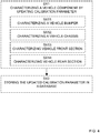
- FIG 3 is a flowchart illustrating methods according to the present disclosure, performed by a sensor signal processing unit such as the sensor signal processing unit 100 discussed in connection to Figure 1 above.
- the flowchart illustrates a method performed by a sensor signal processing unit 100 for calibrating output signals 115 from radar sensors 110.
- the method comprises selecting S2 a calibration object 130 located in a field of view of the radar sensors 110, and generating S3 expected sensor output signals 141 corresponding to detection of the calibration object 130, based on a model 140 of the calibration object 130.
- the method also comprises receiving S4 sensor output signals 151 from the radar sensors associated with detection of the calibration object 130, and updating S5 a calibration parameter 120 of the radar sensors based on a comparison 165 between the expected sensor output signals 141 and the received sensor output signals 151, wherein the updated calibration parameters comprise calibration information for calibrating a value of the radar sensor output signals 115.
- the calibrated value of the radar sensor output signals 115 comprises any of a phase value, an amplitude value, a complex signal value, or a polar coordinate signal value.
- the calibration parameters are here applied on 'raw' sensor output signals, rather than on the relatively abstract level of coordinates and bearings.
- US 6,778,928 B2 restricts operation to calibration using stationary or so-called 'quasi-stationary' objects. No such restriction is made in the methods illustrated in Figure 3 .
- US 6,778,928 B2 teaches a joint optimization of model parameters and calibration parameters. This joint approach necessitates control over the algorithms that supply the model data from the 'model world.
- the methods illustrated in Fig. 3 may, according to some aspects, operate only on calibration parameters, without access to adjustable model parameters.
- the method comprises initializing S1 the calibration parameter of the radar sensors based on a type of a vehicle component arranged in a vicinity of the radar sensors.
- the proposed calibration method can be used to calibrate radar-based sensor systems mounted on a variety of different bumpers and on a variety of different types of vehicles.
- the resulting calibration data can be stored in a memory.
- a newly produced vehicle, or a vehicle in need of calibration parameter initialization can then be initialized to the calibration parameter value corresponding to the vehicle type and vehicle component arrangement. This way, vehicle type specific calibration initialization parameter values may be obtained.
- This type of initialization is also advantageous in that it can be used with radar-based sensor systems not comprising the sensor signal processing unit as disclosed herein.
- some vehicles may comprise on-board radar-based sensor systems but lack a capability of continuous radar sensor calibration.
- Such vehicles can use a fixed calibration parameter based on the type of vehicle components arranged in a vicinity of the radar sensors.
- the method comprises estimating S21 a level of stationarity of the selected calibration object, or estimating a probability that the selected calibration object corresponds to a stationary object.
- the proposed method does not rely on the presence of a stationary or 'quasi-stationary' object in the field of view of sensors.
- Some objects suitable for calibration may be stationary during certain periods of time, and non-stationary otherwise.
- a parked car may be suitable as calibration object, and selected for use based on a stationary model. However, the parked car may start and pull out of the parking lot. In case this happens, the method will estimate the level of stationarity as low, and either update the model used for generating the expected sensor output signals, or select another more suitable calibration object.
- Model details and data from a sensor fusion algorithm corresponding to the calibration objects may be used in the estimation of stationarity, e.g., an estimated object type classification;
- An object having a pedestrian type classification is more likely to move than, e.g., an object having a parked vehicle type classification.
- the parked vehicle is again more likely to move than a permanent structure such as a building.
- the method comprises selecting S22 a non-stationary object as the calibration object.
- the proposed method does not rely on the presence of a stationary or 'quasi-stationary' object in the field of view of sensors.
- Some objects suitable for calibration may be non-stationary.
- An object can be either stationary or non-stationary.
- a non-stationary object having physical characteristics determined with high accuracy may in some cases even be preferred over a stationary object with more uncertain physical characteristics.
- the level of accuracy in determined object characteristics may be obtained from an estimate of variance in a sensor fusion algorithm based on, e.g., a Kalman filter or a particle filter implementation.
- the method comprises selecting S23 an active radar signal source as the calibration object. It is appreciated that not only passive reflective objects can be used as calibration objects. Radar repeater devices and relays may improve the accuracy of the calibration parameter. As an example, consider an active repeater installed in connection to a vehicle assembly line. As the vehicles pass the radar repeater, the sensor signal processing units receive a strong radar signal from the radar repeater. This strong radar signal is less prone to corruption by, e.g., thermal noise. Also, the physical characteristics of the radar repeater, such as its exact location in relation to the assembly line and geometrical shape can be made known to the sensor signal processing unit 100.
- the method comprises terminating S24 a calibration parameter update procedure in case no calibration object is found. There may be periods of time when no suitable calibration object exists in the field of view of the radar-based sensors. In this case the method may terminate or be put on hold until a suitable calibration object is found.
- the method comprises receiving S41 a phase difference signal corresponding to a difference in received phase between detection of the calibration object by the first radar antenna, and detection of the calibration object by the second radar antenna.
- a phase difference signal corresponding to a difference in received phase between detection of the calibration object by the first radar antenna, and detection of the calibration object by the second radar antenna.
- the calibration parameter comprises a hardware-related parameter S51 of the radar sensors, the hardware parameters being associated with any of a frequency offset value, a phase offset value, an amplitude gain adjustment value, a setting of one or more equalizer filter tap values, a power supply value.
- fundamental hardware parameters of the radar-based sensor may be calibrated by the disclosed methods.
- the calibration parameter comprises a parameter associated with a geometrical property of the selected calibration object S52.
- Figure 4 is a flowchart illustrating additional methods according to the present disclosure.
- Figure 4 highlights aspects of the disclosed method, which methods comprise characterizing SX1 a vehicle component by the updated calibration parameter. This aspect was discussed above in connection to the initialization part of the disclosed method.
- This type of characterization is advantageous in that it provides calibration parameters for use with various vehicles having different arrangements in terms of bumper geometry, front end geometry, and the like.
- the proposed calibration method can be used to calibrate radar-based sensor systems mounted on a variety of different bumpers and on a variety of different types of vehicles.
- the resulting calibration data can be stored in memory.
- a newly produced vehicle, or a vehicle in need of calibration parameter initialization can then be initialized to the calibration parameter value corresponding to the vehicle type and vehicle component arrangement. This way, vehicle type specific calibration initialization parameter values may be obtained.
- the method also comprises storing the updated calibration parameter SX2 in a database of car component characterizations.
- the storing is advantageous in that the stored calibration parameters can be used with radar-based sensor systems not comprising the sensor signal processing unit as disclosed herein.
- vehicles which comprise on-board radar-based sensor systems but without capability of continuous radar sensor calibration.
- Such vehicles can use a fixed calibration parameter based on the type of vehicle components arranged in a vicinity of the radar sensors.
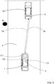
- Figure 5 illustrates an example application of a sensor signal processing unit 100 system mounted on a vehicle 1 having a front section 2.
- the vehicle travels on a roadway 5 and has two objects in its sensors field of view.
- a non-stationary object 6a a car, is located down the road 5, and a stationary object 6b is located on the road-side.
- the radar-based sensor system transmits radar signals 9a and receives reflections 9b from reflective surfaces 8 on the vehicle 6a.
- models of both the non-stationary object 6a and the stationary object 6b can be used in the calibration methods as disclosed herein.
- Figure 6 shows graphs illustrating results of operations in a sensor signal processing system.
- the graphs are the result of an approximately 500 meters long test drive on a typical city-street. Based on that 500m measurement self-calibration was running as disclosed herein.
- a calibration routine may be performed according to the following sequence of operations.
- Step 1 For an in-phase mode of operation and an out-of-phase mode of operation, and a radar-based system with four receive antennas, three phase difference signals are generated by determining phase differences between sensor output signals.
- In-phase mode operation phase difference sensor output signals are denoted Rx1Ref, Rx2Ref, and Rx3Ref
- out-of-phase mode of operation phase difference sensor output signals are denoted Rx1Err, Rx2Err, and Rx3Err.
- the 2N antennae are implemented by series feed patch arrays that have a 180° phase shifter in-between the two antenna rows.
- the reference pattern or sum pattern i.e., the in-phase mode of operation
- the error pattern or delta pattern i.e., the out-of-phase mode of operation
- the two modes of operation are illustrated in Figure 7A .
- Step 2 Based on prior knowledge of the targets (e.g. that they are stationary), doppler information leads to angle or bearing information.
- a radar consisting of 4 receive antennas (not equidistant) the measured phase difference is ambiguous.
- the measured phase difference ambiguity gets resolved by prior knowledge obtained from, e.g., a sensor fusion unit 170. It is advantageous if the accuracy of prior knowledge information is at least better than the ambiguity of the receive antenna having the largest antenna spacing.
- doppler/host velocity ratio is filtered via a filter, e.g., a growing memory filter.
- the data domain ranges from -180 degrees to 180 degrees in 2-degree steps.
- the Doppler-ratio (measured Doppler divided by actual host velocity (velocity of host car)) is determined over measured phase differences. Since the host velocity relies on "car-wheel-ticks" it is crucial that the internally known wheel size represents reality. In a case it is off e.g. 10% the curves maximum will not be the value 1 but greater.
- This sensor output signal is plotted in Figure 6A .
- Figure 6A is also plotted the expected sensor output signal based on a model of a stationary calibration object located in a field of view of the radar sensors. A comparison can now be made between the generated expected sensor output signals 141 and the received sensor output signals 151.
- Step 3 Host velocity correction is now applied and a phase difference error for each step gets calculated.
- phase difference error corresponds to the comparison result 165, and it is plotted in Figure 6B .
- Step 4 The calibration parameter is now adjusted such that the determined comparison result, or error signal, is minimized. For instance, a least-mean-squares method can be used to minimize a squared value of the determined error signal.
- Figure 7C illustrates the result of calibration. To the left is shown a phase error plot before calibration, and to the right a phase error plot after calibration. It is seen that the phase error is significantly decreased due to the execution of the disclosed calibration method.
- Figure 6A illustrates radar signal processing according to the above discussion where the expected sensor output signals 141 corresponding to detection of the calibration object 130 is based on a model 140 of the calibration object 130 comprising measured Doppler frequency velocity of a stationary target divided by host velocity, V doppler /V host .
- the model underlying curve 151 in Figure 6A is given by sin acos dopplerRatio ⁇ mounting angle where mounting angle corresponds to an estimate of sensor mounting angle in relation to vehicle bore-sight.
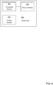
- Figure 8 schematically illustrates components of a control unit 800.
- a computer-readable medium may include removable and non-removable storage devices including, but not limited to, Read Only Memory, ROM, Random Access Memory, RAM, compact discs, CDs, digital versatile discs, DVDs, etc.
- program modules may include routines, programs, objects, components, data structures, etc. that performs particular tasks or implement particular abstract data types.
- Computer-executable instructions, associated data structures, and program modules represent examples of program code for executing steps of the methods disclosed herein. The particular sequence of such executable instructions or associated data structures represents examples of corresponding acts for implementing the functions described in such steps or processes.
- the disclosed sensor signal processing units and control units comprise processing circuitry.
- the processing circuitry may be any suitable type of computation unit, e.g. a microprocessor, digital signal processor, DSP, field programmable gate array, FPGA, or application specific integrated circuit, ASIC, or any other form of circuitry. It should be appreciated that the processing circuitry need not be provided as a single unit but may be provided as any number of units or circuitry.
- FIG. 8 schematically illustrates, in terms of a number of functional units, the components of a control unit 800 according to an embodiment.
- Processing circuitry 810 is provided using any combination of one or more of a suitable central processing unit (CPU), multiprocessor, microcontroller, digital signal processor (DSP), etc., capable of executing software instructions stored in a computer program product, e.g. in the form of a storage medium 830.
- the processing circuitry 810 may further be provided as at least one application specific integrated circuit (ASIC), or field programmable gate array (FPGA).
- ASIC application specific integrated circuit
- FPGA field programmable gate array
- the processing circuitry 810 is configured to cause the control unit 800 to perform a set of operations, or steps. These operations, or steps, was discussed above in connection to Fig. 3
- the storage medium 830 may store the set of operations
- the processing circuitry 810 may be configured to retrieve the set of operations from the storage medium 830 to cause the control node 800 to perform the set of operations.
- the set of operations may be provided as a set of executable instructions.
- the processing circuitry 810 is thereby arranged to execute methods as herein disclosed.
- the storage medium 830 may also comprise persistent storage, which, for example, can be any single one or combination of magnetic memory, optical memory, solid state memory or even remotely mounted memory.
- the control unit 800 may further comprise a communications interface 820 for communications with at least one sensor device, i.e., a sensor interface 820.
- the sensor interface 820 may comprise one or more transmitters and receivers, comprising analogue and digital components and a suitable number ports for wireline or wireless communication.
- the processing circuitry 810 is adapted to control the general operation of the control node 800 e.g. by sending data and control signals to the sensor interface 820 and the storage medium 830, by receiving data and reports from the sensor interface 820, and by retrieving data and instructions from the storage medium 830.
- Other components, as well as the related functionality, of the control node 800 are omitted in order not to obscure the concepts presented herein.
Landscapes
- Engineering & Computer Science (AREA)
- Radar, Positioning & Navigation (AREA)
- Remote Sensing (AREA)
- Physics & Mathematics (AREA)
- Computer Networks & Wireless Communication (AREA)
- General Physics & Mathematics (AREA)
- Electromagnetism (AREA)
- Radar Systems Or Details Thereof (AREA)
Priority Applications (1)
| Application Number | Priority Date | Filing Date | Title |
|---|---|---|---|
| EP17197920.6A EP3477334A1 (fr) | 2017-10-24 | 2017-10-24 | Étalonnage de détecteur radar automatique |
Applications Claiming Priority (1)
| Application Number | Priority Date | Filing Date | Title |
|---|---|---|---|
| EP17197920.6A EP3477334A1 (fr) | 2017-10-24 | 2017-10-24 | Étalonnage de détecteur radar automatique |
Publications (1)
| Publication Number | Publication Date |
|---|---|
| EP3477334A1 true EP3477334A1 (fr) | 2019-05-01 |
Family
ID=60162093
Family Applications (1)
| Application Number | Title | Priority Date | Filing Date |
|---|---|---|---|
| EP17197920.6A Ceased EP3477334A1 (fr) | 2017-10-24 | 2017-10-24 | Étalonnage de détecteur radar automatique |
Country Status (1)
| Country | Link |
|---|---|
| EP (1) | EP3477334A1 (fr) |
Cited By (8)
| Publication number | Priority date | Publication date | Assignee | Title |
|---|---|---|---|---|
| CN112346023A (zh) * | 2019-08-06 | 2021-02-09 | 北京华航无线电测量研究所 | 一种被动雷达的幅度自校准模块 |
| CN113204006A (zh) * | 2021-04-22 | 2021-08-03 | 安徽江淮汽车集团股份有限公司 | 超声波雷达距离标定系统和方法 |
| CN113256734A (zh) * | 2021-05-20 | 2021-08-13 | 东风汽车集团股份有限公司 | 一种车载感知传感器标定方法、系统及电子设备 |
| CN113256696A (zh) * | 2021-06-28 | 2021-08-13 | 中国人民解放军国防科技大学 | 基于自然场景的激光雷达和相机的外参标定方法 |
| CN113534136A (zh) * | 2020-04-22 | 2021-10-22 | 郑州宇通客车股份有限公司 | 一种车内遗留儿童检测方法及系统 |
| CN113739837A (zh) * | 2020-10-19 | 2021-12-03 | 中国电子科技集团公司第三十八研究所 | 一种标准仪器的状态预测处理系统 |
| CN113805161A (zh) * | 2021-09-14 | 2021-12-17 | 广州文远知行科技有限公司 | 超声波传感器标定方法、系统、控制设备及存储介质 |
| CN117930160A (zh) * | 2024-03-21 | 2024-04-26 | 福思(杭州)智能科技有限公司 | 毫米波雷达的角度补偿方法、装置和存储介质及电子设备 |
Citations (6)
| Publication number | Priority date | Publication date | Assignee | Title |
|---|---|---|---|---|
| US6025797A (en) * | 1997-07-22 | 2000-02-15 | Denso Corporation | Angular shift determining apparatus for determining angular shift of central axis of radar used in automotive obstacle detection system |
| US6087995A (en) * | 1999-02-17 | 2000-07-11 | Anritsu Company | Universal autoradar antenna alignment system |
| US6778928B2 (en) | 1999-12-24 | 2004-08-17 | Robert Bosch Gmbh | Method of calibrating a sensor system |
| US20110153268A1 (en) * | 2009-12-17 | 2011-06-23 | Ruediger Jordan | Object sensor |
| DE102011015935A1 (de) * | 2011-04-02 | 2012-10-04 | Valeo Schalter Und Sensoren Gmbh | Verfahren zum Bestimmen eines Korrekturwerts für die Messung eines Zielwinkels mit einem Radargerät, Fahrerassistenzsystem und Kraftfahrzeug |
| DE102014017917B3 (de) * | 2014-12-04 | 2015-11-12 | Audi Ag | Verfahren zum Konfigurieren wenigstens eines an einer von mehreren Einbaupositionen in einem Kraftfahrzeug verbauten Radarsensors hinsichtlich der Einbauposition und Kraftfahrzeug |
-
2017
- 2017-10-24 EP EP17197920.6A patent/EP3477334A1/fr not_active Ceased
Patent Citations (6)
| Publication number | Priority date | Publication date | Assignee | Title |
|---|---|---|---|---|
| US6025797A (en) * | 1997-07-22 | 2000-02-15 | Denso Corporation | Angular shift determining apparatus for determining angular shift of central axis of radar used in automotive obstacle detection system |
| US6087995A (en) * | 1999-02-17 | 2000-07-11 | Anritsu Company | Universal autoradar antenna alignment system |
| US6778928B2 (en) | 1999-12-24 | 2004-08-17 | Robert Bosch Gmbh | Method of calibrating a sensor system |
| US20110153268A1 (en) * | 2009-12-17 | 2011-06-23 | Ruediger Jordan | Object sensor |
| DE102011015935A1 (de) * | 2011-04-02 | 2012-10-04 | Valeo Schalter Und Sensoren Gmbh | Verfahren zum Bestimmen eines Korrekturwerts für die Messung eines Zielwinkels mit einem Radargerät, Fahrerassistenzsystem und Kraftfahrzeug |
| DE102014017917B3 (de) * | 2014-12-04 | 2015-11-12 | Audi Ag | Verfahren zum Konfigurieren wenigstens eines an einer von mehreren Einbaupositionen in einem Kraftfahrzeug verbauten Radarsensors hinsichtlich der Einbauposition und Kraftfahrzeug |
Cited By (11)
| Publication number | Priority date | Publication date | Assignee | Title |
|---|---|---|---|---|
| CN112346023A (zh) * | 2019-08-06 | 2021-02-09 | 北京华航无线电测量研究所 | 一种被动雷达的幅度自校准模块 |
| CN113534136A (zh) * | 2020-04-22 | 2021-10-22 | 郑州宇通客车股份有限公司 | 一种车内遗留儿童检测方法及系统 |
| CN113534136B (zh) * | 2020-04-22 | 2023-07-28 | 宇通客车股份有限公司 | 一种车内遗留儿童检测方法及系统 |
| CN113739837A (zh) * | 2020-10-19 | 2021-12-03 | 中国电子科技集团公司第三十八研究所 | 一种标准仪器的状态预测处理系统 |
| CN113204006A (zh) * | 2021-04-22 | 2021-08-03 | 安徽江淮汽车集团股份有限公司 | 超声波雷达距离标定系统和方法 |
| CN113256734A (zh) * | 2021-05-20 | 2021-08-13 | 东风汽车集团股份有限公司 | 一种车载感知传感器标定方法、系统及电子设备 |
| CN113256734B (zh) * | 2021-05-20 | 2023-05-09 | 岚图汽车科技有限公司 | 一种车载感知传感器标定方法、系统及电子设备 |
| CN113256696A (zh) * | 2021-06-28 | 2021-08-13 | 中国人民解放军国防科技大学 | 基于自然场景的激光雷达和相机的外参标定方法 |
| CN113805161A (zh) * | 2021-09-14 | 2021-12-17 | 广州文远知行科技有限公司 | 超声波传感器标定方法、系统、控制设备及存储介质 |
| CN113805161B (zh) * | 2021-09-14 | 2024-05-03 | 广州文远知行科技有限公司 | 超声波传感器标定方法、系统、控制设备及存储介质 |
| CN117930160A (zh) * | 2024-03-21 | 2024-04-26 | 福思(杭州)智能科技有限公司 | 毫米波雷达的角度补偿方法、装置和存储介质及电子设备 |
Similar Documents
| Publication | Publication Date | Title |
|---|---|---|
| EP3477334A1 (fr) | Étalonnage de détecteur radar automatique | |
| US11237248B2 (en) | Automated vehicle radar system with self-calibration | |
| US10690743B2 (en) | Doppler measurements to resolve angle of arrival ambiguity of wide aperture radar | |
| CN111521989B (zh) | 用于雷达系统中的超分辨率的深度学习 | |
| JP5009282B2 (ja) | 複数のレーダをコヒーレントに組み合わせるシステム及び方法 | |
| CN111708026A (zh) | 具有前向和后向差分共阵列处理的高分辨率汽车雷达系统 | |
| EP3913391A1 (fr) | Traitement de signaux radar | |
| US20210025972A1 (en) | Method for calibrating a mimo radar sensor for motor vehicles | |
| JP2020525771A (ja) | 自動車用検出システムにおけるセンサの位置合わせ及びアンテナパターン応答値の較正のための装置及び方法 | |
| US10261172B2 (en) | Radar apparatus for vehicle and method of removing ghost of the same | |
| EP3754359A1 (fr) | Procédé de détermination d'angles d'alignement de capteurs radar pour un contrôleur d'alignement automatique de radar de véhicule routier | |
| CN113330326A (zh) | 用于校准多输入多输出雷达传感器的设备和方法 | |
| US10754024B2 (en) | Object-sensing system for vehicle and object-sensing method for vehicle | |
| CN112313525A (zh) | 雷达传感器系统 | |
| US20190383900A1 (en) | Joint optimization of antenna spacing and target angle estimation in a radar system | |
| CN110940973B (zh) | 一种用于雷达目标检测的角度测量方法及装置 | |
| JP6294853B2 (ja) | レーダ装置およびレーダ装置の制御方法 | |
| EP3761054A1 (fr) | Étalonnage d'un capteur basé sur des chaînes de détections | |
| Bobaru et al. | A Method for Automatic Radar Azimuth Calibration using Stationary Targets | |
| EP4253994A1 (fr) | Étalonnage d'un capteur basé sur des chaînes de détections | |
| US20240094377A1 (en) | High resolution radar simulation to train vehicle radar system neural network | |
| CN115494495B (zh) | 用于估计对象的高度的方法 | |
| US20230176179A1 (en) | Radar system with enhanced processing for increased contrast ratio, improved angular separability and accuracy, and elimination of ghost targets in a single-snapshot | |
| EP4249942A1 (fr) | Détection d'alignement pour un émetteur/récepteur de radar de véhicule | |
| US20230051791A1 (en) | Method for determining at least one piece of object information about at least one object sensed by means of a radar system and radar system |
Legal Events
| Date | Code | Title | Description |
|---|---|---|---|
| PUAI | Public reference made under article 153(3) epc to a published international application that has entered the european phase |
Free format text: ORIGINAL CODE: 0009012 |
|
| STAA | Information on the status of an ep patent application or granted ep patent |
Free format text: STATUS: THE APPLICATION HAS BEEN PUBLISHED |
|
| AK | Designated contracting states |
Kind code of ref document: A1 Designated state(s): AL AT BE BG CH CY CZ DE DK EE ES FI FR GB GR HR HU IE IS IT LI LT LU LV MC MK MT NL NO PL PT RO RS SE SI SK SM TR |
|
| AX | Request for extension of the european patent |
Extension state: BA ME |
|
| STAA | Information on the status of an ep patent application or granted ep patent |
Free format text: STATUS: REQUEST FOR EXAMINATION WAS MADE |
|
| 17P | Request for examination filed |
Effective date: 20191030 |
|
| RBV | Designated contracting states (corrected) |
Designated state(s): AL AT BE BG CH CY CZ DE DK EE ES FI FR GB GR HR HU IE IS IT LI LT LU LV MC MK MT NL NO PL PT RO RS SE SI SK SM TR |
|
| STAA | Information on the status of an ep patent application or granted ep patent |
Free format text: STATUS: EXAMINATION IS IN PROGRESS |
|
| 17Q | First examination report despatched |
Effective date: 20210208 |
|
| STAA | Information on the status of an ep patent application or granted ep patent |
Free format text: STATUS: EXAMINATION IS IN PROGRESS |
|
| STAA | Information on the status of an ep patent application or granted ep patent |
Free format text: STATUS: THE APPLICATION HAS BEEN REFUSED |
|
| 18R | Application refused |
Effective date: 20231006 |