EP3476432B1 - Dispositif de thérapie de haute tension - Google Patents
Dispositif de thérapie de haute tension Download PDFInfo
- Publication number
- EP3476432B1 EP3476432B1 EP18200923.3A EP18200923A EP3476432B1 EP 3476432 B1 EP3476432 B1 EP 3476432B1 EP 18200923 A EP18200923 A EP 18200923A EP 3476432 B1 EP3476432 B1 EP 3476432B1
- Authority
- EP
- European Patent Office
- Prior art keywords
- therapy
- subunit
- subunits
- arrangement
- voltage
- Prior art date
- Legal status (The legal status is an assumption and is not a legal conclusion. Google has not performed a legal analysis and makes no representation as to the accuracy of the status listed.)
- Active
Links
- 238000002560 therapeutic procedure Methods 0.000 claims description 132
- 238000004891 communication Methods 0.000 claims description 36
- 238000001514 detection method Methods 0.000 claims description 24
- 239000003990 capacitor Substances 0.000 claims description 7
- 230000001225 therapeutic effect Effects 0.000 claims description 7
- 230000035939 shock Effects 0.000 description 15
- 210000000038 chest Anatomy 0.000 description 14
- 230000001360 synchronised effect Effects 0.000 description 14
- 230000000638 stimulation Effects 0.000 description 12
- 238000000034 method Methods 0.000 description 9
- 239000007943 implant Substances 0.000 description 7
- 238000007920 subcutaneous administration Methods 0.000 description 6
- 210000001015 abdomen Anatomy 0.000 description 5
- 239000004020 conductor Substances 0.000 description 5
- 230000008569 process Effects 0.000 description 5
- 230000000747 cardiac effect Effects 0.000 description 4
- 238000013194 cardioversion Methods 0.000 description 4
- 238000013461 design Methods 0.000 description 4
- 230000003601 intercostal effect Effects 0.000 description 4
- 238000005259 measurement Methods 0.000 description 4
- 210000001562 sternum Anatomy 0.000 description 4
- 241001433070 Xiphoides Species 0.000 description 3
- 230000005540 biological transmission Effects 0.000 description 3
- 230000003287 optical effect Effects 0.000 description 3
- 239000013598 vector Substances 0.000 description 3
- 210000002417 xiphoid bone Anatomy 0.000 description 3
- 108010001267 Protein Subunits Proteins 0.000 description 2
- 238000004458 analytical method Methods 0.000 description 2
- 206010003119 arrhythmia Diseases 0.000 description 2
- 230000002457 bidirectional effect Effects 0.000 description 2
- 230000008878 coupling Effects 0.000 description 2
- 238000010168 coupling process Methods 0.000 description 2
- 238000005859 coupling reaction Methods 0.000 description 2
- 230000000694 effects Effects 0.000 description 2
- 238000001827 electrotherapy Methods 0.000 description 2
- 238000002513 implantation Methods 0.000 description 2
- 238000009413 insulation Methods 0.000 description 2
- 239000000463 material Substances 0.000 description 2
- 210000003205 muscle Anatomy 0.000 description 2
- 210000005036 nerve Anatomy 0.000 description 2
- 230000010363 phase shift Effects 0.000 description 2
- 230000035790 physiological processes and functions Effects 0.000 description 2
- 229920001296 polysiloxane Polymers 0.000 description 2
- 230000001681 protective effect Effects 0.000 description 2
- 210000001519 tissue Anatomy 0.000 description 2
- 230000001960 triggered effect Effects 0.000 description 2
- 210000000683 abdominal cavity Anatomy 0.000 description 1
- 230000004913 activation Effects 0.000 description 1
- 230000006978 adaptation Effects 0.000 description 1
- 239000004760 aramid Substances 0.000 description 1
- 229920006231 aramid fiber Polymers 0.000 description 1
- 230000006793 arrhythmia Effects 0.000 description 1
- 230000001746 atrial effect Effects 0.000 description 1
- 238000005452 bending Methods 0.000 description 1
- 239000000560 biocompatible material Substances 0.000 description 1
- 230000036772 blood pressure Effects 0.000 description 1
- 230000015556 catabolic process Effects 0.000 description 1
- 238000011982 device technology Methods 0.000 description 1
- 238000007599 discharging Methods 0.000 description 1
- 238000005516 engineering process Methods 0.000 description 1
- 238000011156 evaluation Methods 0.000 description 1
- 230000002349 favourable effect Effects 0.000 description 1
- 239000000835 fiber Substances 0.000 description 1
- 210000002837 heart atrium Anatomy 0.000 description 1
- 210000005003 heart tissue Anatomy 0.000 description 1
- 230000000004 hemodynamic effect Effects 0.000 description 1
- 230000001976 improved effect Effects 0.000 description 1
- 230000000977 initiatory effect Effects 0.000 description 1
- 238000007726 management method Methods 0.000 description 1
- 238000004519 manufacturing process Methods 0.000 description 1
- 239000002184 metal Substances 0.000 description 1
- 238000012544 monitoring process Methods 0.000 description 1
- 230000000877 morphologic effect Effects 0.000 description 1
- 210000004165 myocardium Anatomy 0.000 description 1
- 230000001766 physiological effect Effects 0.000 description 1
- 229920002635 polyurethane Polymers 0.000 description 1
- 239000004814 polyurethane Substances 0.000 description 1
- 230000035484 reaction time Effects 0.000 description 1
- 230000009467 reduction Effects 0.000 description 1
- 230000002787 reinforcement Effects 0.000 description 1
- 230000004044 response Effects 0.000 description 1
- 230000033764 rhythmic process Effects 0.000 description 1
- 238000000926 separation method Methods 0.000 description 1
- 238000011125 single therapy Methods 0.000 description 1
- 230000004936 stimulating effect Effects 0.000 description 1
- 238000001356 surgical procedure Methods 0.000 description 1
- 238000012360 testing method Methods 0.000 description 1
- 238000002604 ultrasonography Methods 0.000 description 1
- 230000002861 ventricular Effects 0.000 description 1
Images


Classifications
-
- A—HUMAN NECESSITIES
- A61—MEDICAL OR VETERINARY SCIENCE; HYGIENE
- A61N—ELECTROTHERAPY; MAGNETOTHERAPY; RADIATION THERAPY; ULTRASOUND THERAPY
- A61N1/00—Electrotherapy; Circuits therefor
- A61N1/18—Applying electric currents by contact electrodes
- A61N1/32—Applying electric currents by contact electrodes alternating or intermittent currents
- A61N1/38—Applying electric currents by contact electrodes alternating or intermittent currents for producing shock effects
- A61N1/39—Heart defibrillators
- A61N1/3968—Constructional arrangements, e.g. casings
-
- A—HUMAN NECESSITIES
- A61—MEDICAL OR VETERINARY SCIENCE; HYGIENE
- A61N—ELECTROTHERAPY; MAGNETOTHERAPY; RADIATION THERAPY; ULTRASOUND THERAPY
- A61N1/00—Electrotherapy; Circuits therefor
- A61N1/18—Applying electric currents by contact electrodes
- A61N1/32—Applying electric currents by contact electrodes alternating or intermittent currents
- A61N1/38—Applying electric currents by contact electrodes alternating or intermittent currents for producing shock effects
- A61N1/39—Heart defibrillators
- A61N1/3956—Implantable devices for applying electric shocks to the heart, e.g. for cardioversion
-
- A—HUMAN NECESSITIES
- A61—MEDICAL OR VETERINARY SCIENCE; HYGIENE
- A61N—ELECTROTHERAPY; MAGNETOTHERAPY; RADIATION THERAPY; ULTRASOUND THERAPY
- A61N1/00—Electrotherapy; Circuits therefor
- A61N1/18—Applying electric currents by contact electrodes
- A61N1/32—Applying electric currents by contact electrodes alternating or intermittent currents
- A61N1/36—Applying electric currents by contact electrodes alternating or intermittent currents for stimulation
- A61N1/372—Arrangements in connection with the implantation of stimulators
- A61N1/375—Constructional arrangements, e.g. casings
- A61N1/37512—Pacemakers
-
- A—HUMAN NECESSITIES
- A61—MEDICAL OR VETERINARY SCIENCE; HYGIENE
- A61N—ELECTROTHERAPY; MAGNETOTHERAPY; RADIATION THERAPY; ULTRASOUND THERAPY
- A61N1/00—Electrotherapy; Circuits therefor
- A61N1/18—Applying electric currents by contact electrodes
- A61N1/32—Applying electric currents by contact electrodes alternating or intermittent currents
- A61N1/38—Applying electric currents by contact electrodes alternating or intermittent currents for producing shock effects
- A61N1/39—Heart defibrillators
- A61N1/3975—Power supply
-
- A—HUMAN NECESSITIES
- A61—MEDICAL OR VETERINARY SCIENCE; HYGIENE
- A61B—DIAGNOSIS; SURGERY; IDENTIFICATION
- A61B5/00—Measuring for diagnostic purposes; Identification of persons
- A61B5/02—Detecting, measuring or recording pulse, heart rate, blood pressure or blood flow; Combined pulse/heart-rate/blood pressure determination; Evaluating a cardiovascular condition not otherwise provided for, e.g. using combinations of techniques provided for in this group with electrocardiography or electroauscultation; Heart catheters for measuring blood pressure
- A61B5/021—Measuring pressure in heart or blood vessels
- A61B5/0215—Measuring pressure in heart or blood vessels by means inserted into the body
-
- A—HUMAN NECESSITIES
- A61—MEDICAL OR VETERINARY SCIENCE; HYGIENE
- A61B—DIAGNOSIS; SURGERY; IDENTIFICATION
- A61B5/00—Measuring for diagnostic purposes; Identification of persons
- A61B5/02—Detecting, measuring or recording pulse, heart rate, blood pressure or blood flow; Combined pulse/heart-rate/blood pressure determination; Evaluating a cardiovascular condition not otherwise provided for, e.g. using combinations of techniques provided for in this group with electrocardiography or electroauscultation; Heart catheters for measuring blood pressure
- A61B5/024—Detecting, measuring or recording pulse rate or heart rate
- A61B5/0245—Detecting, measuring or recording pulse rate or heart rate by using sensing means generating electric signals, i.e. ECG signals
-
- A—HUMAN NECESSITIES
- A61—MEDICAL OR VETERINARY SCIENCE; HYGIENE
- A61B—DIAGNOSIS; SURGERY; IDENTIFICATION
- A61B5/00—Measuring for diagnostic purposes; Identification of persons
- A61B5/24—Detecting, measuring or recording bioelectric or biomagnetic signals of the body or parts thereof
- A61B5/316—Modalities, i.e. specific diagnostic methods
- A61B5/318—Heart-related electrical modalities, e.g. electrocardiography [ECG]
-
- A—HUMAN NECESSITIES
- A61—MEDICAL OR VETERINARY SCIENCE; HYGIENE
- A61B—DIAGNOSIS; SURGERY; IDENTIFICATION
- A61B5/00—Measuring for diagnostic purposes; Identification of persons
- A61B5/68—Arrangements of detecting, measuring or recording means, e.g. sensors, in relation to patient
- A61B5/6846—Arrangements of detecting, measuring or recording means, e.g. sensors, in relation to patient specially adapted to be brought in contact with an internal body part, i.e. invasive
- A61B5/6847—Arrangements of detecting, measuring or recording means, e.g. sensors, in relation to patient specially adapted to be brought in contact with an internal body part, i.e. invasive mounted on an invasive device
- A61B5/686—Permanently implanted devices, e.g. pacemakers, other stimulators, biochips
-
- A—HUMAN NECESSITIES
- A61—MEDICAL OR VETERINARY SCIENCE; HYGIENE
- A61B—DIAGNOSIS; SURGERY; IDENTIFICATION
- A61B5/00—Measuring for diagnostic purposes; Identification of persons
- A61B5/68—Arrangements of detecting, measuring or recording means, e.g. sensors, in relation to patient
- A61B5/6846—Arrangements of detecting, measuring or recording means, e.g. sensors, in relation to patient specially adapted to be brought in contact with an internal body part, i.e. invasive
- A61B5/6867—Arrangements of detecting, measuring or recording means, e.g. sensors, in relation to patient specially adapted to be brought in contact with an internal body part, i.e. invasive specially adapted to be attached or implanted in a specific body part
- A61B5/6869—Heart
-
- A—HUMAN NECESSITIES
- A61—MEDICAL OR VETERINARY SCIENCE; HYGIENE
- A61B—DIAGNOSIS; SURGERY; IDENTIFICATION
- A61B5/00—Measuring for diagnostic purposes; Identification of persons
- A61B5/72—Signal processing specially adapted for physiological signals or for diagnostic purposes
- A61B5/7271—Specific aspects of physiological measurement analysis
- A61B5/7285—Specific aspects of physiological measurement analysis for synchronising or triggering a physiological measurement or image acquisition with a physiological event or waveform, e.g. an ECG signal
- A61B5/7292—Prospective gating, i.e. predicting the occurrence of a physiological event for use as a synchronisation signal
Definitions
- the invention relates to devices and systems for electrical stimulation therapy on a patient.
- the invention relates to the field of cardiac stimulation, in a specific example implantable systems for cardioversion and defibrillation of the heart.
- ICDs implantable systems for cardiac stimulation, cardioversion and defibrillation
- ICDs implantable cardioverter defibrillator
- the electrode lines have one or more electrodes for measuring cardiac potentials and / or delivering stimulation pulses.
- Electrode leads with a shock electrode are able to deliver an intracardiac defibrillation shock in the event of life-threatening cardiac arrhythmias.
- the electrode lines are connected to the implant housing via connector connections integrated in a header module.
- SICD subcutaneous implantable cardioverter defibrillator
- the sICD is implanted under the patient's skin, with at least two electrode poles for delivering the shock being arranged so that the current path (“shock vector”) leads through the areas of the heart to be shocked.
- SICDs are known consisting of an implant housing and connected shock electrode line, the housing being implanted laterally over the ribs near the armpits and the shock electrode line being implanted centrally over the chest.
- a sICD system compared to an ICD system are that there is no need to place an intracardiac electrode, which reduces the risk for the patient.
- Disadvantages of a sICD system are the higher shock energy required due to the longer current path from the shock electrodes to the heart tissue.
- Known sICD systems require high therapy voltages greater than 1400 volts and energies greater than 80 joules per shock.
- the hardware requirements of such sICD systems are accordingly higher than those of conventional ICDs.
- Special, expensive high-voltage components charging circuit, high-voltage capacitors), large-scale layouts to maintain the breakdown distances, etc. are required.
- the special hardware components increase the volume of the implant housing of the sICD, so that the device is significantly larger than conventional ICDs and therefore much more annoying for the patient.
- WO 2016/149623 A1 discloses an implantable medical device that has multiple energy sources, wherein the energy sources can be combined to generate a stimulation voltage.
- a system made up of several implantable medical devices (“subsystems”) is also described, each of which has at least one energy source.
- the implantable medical device or device system is designed to generate a stimulation voltage in which the multiple energy sources are combined.
- a specific phase of the stimulation voltage should be generated from an energy source.
- the final stimulation voltage is composed of the various phases. In terms of hardware, it is possible to combine the individual phases into a stimulation voltage through rapid switching.
- the switches can be part of a control unit or of the pulse generator.
- the object of the present invention to develop a therapy system which does not have the disadvantages mentioned above and which can be implemented more easily and cost-effectively compared to known solutions.
- the invention is intended to solve the problem that therapy devices (implantable or non-implantable) in electrotherapy often have to be designed with a large volume and require the use of expensive special components in order to generate the required energies and voltages for the therapy.
- the solution according to the invention for extravascular defibrillation is intended to ensure an effective therapy voltage without the need for special, high-volume high-voltage components.
- an arrangement for electrical therapy for a patient is described, the arrangement being designed to provide at least one to generate electrical therapy voltage that acts at a therapy location in or on the patient's body.
- the arrangement comprises at least a first and a second subunit, and each subunit has at least one energy store. Each amount of energy that can be stored by a single energy store is less than the amount of energy required to generate the electrical therapy voltage.
- Each sub-unit has at least one of the following components: detection unit for the detection of body parameters, therapy unit for generating and / or delivering an electrical voltage for electrical therapy, control unit and / or communication unit.
- the arrangement is designed such that a sub-unit assumes a master role with regard to the generation and / or delivery of an electrical voltage, and the at least one remaining sub-unit assumes a slave role.
- the invention relates to an arrangement for electrical therapy for a patient, the arrangement having at least two subunits.
- the subunits each provide a voltage for the electrical therapy, each voltage provided by a subunit being lower than the therapeutically effective voltage achieved at a therapy location.
- Each sub-unit has at least one of the following components: Detection unit for the detection of body parameters,
- Therapy unit for generating and / or delivering an electrical voltage for electrical therapy, control unit and / or communication unit.
- a sub-unit assumes a master role with regard to the generation and / or delivery of an electrical voltage.
- the at least one remaining subunit takes on a slave role, so that the at least one subunit in the slave role is based on the subunit in the master role with regard to the time of therapy delivery and / or polarity of therapy delivery and / or duration of therapy delivery
- the required therapy voltage is generated by superimposing partial contributions from several subunits of the arrangement.
- the at least first and second subunits are each designed to generate an electrical voltage using energy from the energy store.
- the arrangement is designed to generate the electrical therapy voltage in which the at least first and second subunit generated voltages are superimposed.
- the voltages generated by the at least two subunits are superimposed such that the amplitude of the superimposed voltage is higher than the amplitude of a voltage generated by a subunit.
- the first sub-unit is arranged in a first outer housing
- the second sub-unit is arranged in a second outer housing.
- the at least first and second subunits are individual components of a therapy system, such as a battery and capacitor. If these high-volume components are housed in separate housings and interconnected, the device volume of such a therapy device is distributed over two individual devices.
- the at least two subunits can also be individual therapy devices, such as subcutaneous implantable cardioverter defibrillators (subcutaneous implantable cardioverter defibrillators, sICDs), or a therapy device and a device for measuring physiological signals without a therapeutic function, such as e.g. In the area of the heart implants, a loop recorder for permanent recording of heart signals.
- the at least first and second subunits are arranged in a common outer housing.
- two therapy devices with the option of generating a voltage for electrical stimulation in one housing.
- the respective voltages are emitted in such a way that they are constructively / essentially phase-synchronously superimposed at the therapy location, so that a high amplitude of the therapy voltage is created.
- Each individual therapy device can be designed to be smaller in terms of volume than if a single therapy device were designed, so that there is a reduction in the total volume and freedom in the design of hardware architecture and arrangement.
- the voltages generated by the at least two subunits are superimposed in such a way that the voltages at the therapy location are essentially phase-synchronous.
- phase-synchronously is to be understood in the context of the invention in such a way that the Voltages are electrical alternating voltages that are superimposed at the therapy location in such a way that the amplitude of the superimposed voltage (which represents the electrical therapy voltage at the therapy location) is higher than each amplitude of the individual alternating voltages.
- the alternating voltages preferably have the same frequencies and a phase shift of 0 ° +/- 2 ⁇ . Small tolerances in phase shift and frequency are unavoidable and are included.
- each sub-unit is designed to communicate with at least one other sub-unit, the communication taking place galvanically, electromagnetically, optically, mechanically and / or acoustically.
- the subunit can have a corresponding transmitter / receiver.
- that subunit receives a master role which detects a body parameter requiring therapy first, ie before all other subunits.
- all subunits detect a physiological signal. As soon as a first subunit measures a physiological event that requires therapy, the subunit generates a voltage and delivers the voltage to the therapy site. As soon as the at least one remaining subunit detects the voltage output from the first subunit, this subunit also begins to generate and output voltage.
- the arrangement has at least one connection arrangement, wherein the at least two subunits are electrically connected by the connection arrangement, and wherein the connection arrangement is electrically isolated from the body of the patient.
- the at least two subunits can be connected in series, anti-series, parallel or in a star shape via the connection arrangement.
- the essential phase synchronicity of the voltages generated by the at least two subunits at the therapy location is generated by the arrangement via the at least one connection arrangement.
- the spatial separation of different components required for generating a therapy voltage on different subunits on a single high-volume device can be dispensed with.
- the invention also includes the idea of allowing individual, smaller-volume therapy devices to work together to generate a high therapy voltage. These smaller therapy devices can each have their own outer housing or be arranged in a common outer housing.
- the invention provides that more than one device are configured in such a way that that they can generate a therapy voltage at the therapy location in coordinated surgery.
- the therapy voltage can be generated by the fact that voltages generated by individual subunits are superimposed or added at the therapy location so that the required therapy energy / therapy voltage can be applied.
- At least one subunit is designed to record an electrocardiogram or a subcutaneous electrocardiogram.
- the subunits are sICDs. By connecting two or more sICDs it is achieved that the voltages at the therapy location add up.
- the subunits are connected in anti-series.
- the subunits each belong to a voltage class below 1000 volts.
- the arrangement according to the invention by superimposing the voltages of the subunits, enables the generation of a therapy voltage that is above the voltage of a subunit (here over 1000 volts, e.g. for extravenous defibrillation). In this way, with cost-efficient device technology of the voltage class less than 1000V, a therapy voltage can be generated that is above 1000 volts.
- the voltages of the sub-units should be superimposed in a phase-synchronous manner. In this way, a targeted generation of an effective therapy voltage is made possible.
- the sub-units involved are synchronized.
- the sub-units are synchronized by means of galvanic, optical, electromagnetic or mechanical / acoustic communication between the sub-units.
- the subject of the invention is a device for high-voltage therapy implanted in a distributed manner in the body, characterized in that the energy-storing elements are housed in spatially separated subunits, which are electrically connected to each other in such a way that the therapeutic effect is realized through the synchronized superposition of partial contributions from the individual subunits.
- the synchronization takes place via galvanic, electromagnetic, optical, mechanical or acoustic communication between the sub-units.
- the arrangement has at least one connecting element, via which the subunits are electrically connected.
- the connecting element is electrically isolated from the patient's body.
- the sub-units have at least one connection in order to connect at least one further sub-unit via a connecting line.
- Each sub-unit has at least one energy-storing element.
- the energy-storing elements are, for example, batteries (primary cells and / or secondary cells) or capacitors or a combination / interconnection of these.
- an interconnection has means for converting the energy, e.g. a charging circuit which, controlled by a control unit, converts low battery voltages into high therapy voltages.
- a charging circuit which, controlled by a control unit, converts low battery voltages into high therapy voltages.
- such an interconnection can have switches / therapy switches which, controlled by the control unit, switch on the therapy voltage or the partial amount of the therapy voltage accordingly.
- the subunits are connected to one another and synchronized in such a way that the therapy current results from the summation of the partial currents generated by the individual subunits.
- the sub-units are connected to one another via more than one connecting conductor, the connecting line contains more than just one conductor.
- one of the sub-units is a master, which implements or programs / configures at least one other sub-unit as a slave.
- Master role means in this context that when a physiological event is detected in a measurement signal that requires therapy, the subunit in the master role takes over the management of coordination, communication, synchronization and therapy delivery with the other subunits. Accordingly, the sub-units in the slave role subordinate themselves to the sub-unit in the master role, i.e. in coordination, communication, synchronization and therapy delivery with the other subunits, they are based on the subunit in the master role.
- the subunit working as a master preferably has a detection unit (including sensing unit) which derives the need for therapy delivery from the analysis of intracorporeal signals.
- An embodiment according to the invention provides that several or all of the subunits record an electrical measurement signal that represents the physiological properties of the patient, for example an electrocardiogram (EKG). Furthermore, several or all subunits are designed to detect events in the electrical measurement signal that require therapy to be delivered. In one embodiment, the sub-unit that comes first to a detection decision assumes the master role. Furthermore, the sub-unit that has become the master can put the other sub-units in a slave role.
- EKG electrocardiogram
- the subunits each include a control unit for triggering the therapy command. Furthermore, the sub-units each have a communication unit, among others. for sending and receiving the therapy command (the communication information in this case is the therapy command). Transmission and reception are also to be understood as galvanic coupling.
- the subunit in the master role forwards a therapy command both to its own therapy unit and to the slave subunits.
- the therapy command is implemented as a signal in which the time of the therapy delivery, the polarity of the therapy delivery and the duration with which the partial energies of the individual subunits are switched on are coded. This ensures that the partial contributions of the individual subunits are superimposed synchronously and with the correct sign.
- the sub-units further comprise devices for measuring time with a high accuracy, e.g. better than 5 ms. If the subunit in the master role recognizes the need to deliver therapy, it can, as an alternative to the other listed methods, plan the delivery of therapy for a specific time, i.e. all sub-units activate their partial contribution synchronously at the time, or plan with a delay by a programmed duration relative to a specific point in time. Such a time can e.g. be the synchronous command to start the loading process.
- the clocks are able to synchronize with external clocks (e.g. radio clock). Alternatively, the clocks only synchronize within the implanted system. The clocks are synchronized either event-controlled at the time of detection or regularly at intervals that ensure an accuracy of better than 5 ms.
- a subunit detects physiological parameters that require therapy and thereupon emits an electrical voltage directed to the therapy site.
- the at least one other subunit detects the voltage output of the first subunit and thereupon also outputs voltage specifically to the therapy location.
- the subunits have an electrode pole that is galvanically coupled to the tissue and is preferably attached to the housing of the subunit (housing pole). In a preferred embodiment, this is the housing of the respective subunit itself, which is then implemented in an electrically conductive (eg metallic) manner.
- This electrode pole can optionally be switched on for the therapy delivery. This information can also come from the subunit in the master role Therapy command must be coded. This electrode pole (housing pole) is optionally also used for sensing.
- additional electrode poles for the sensing function are accommodated on the connecting line between the subunits and are connected to the sensing / detection units.
- Signals from sensing electrodes that are only connected to slave subunits are processed by the sensing / detection unit of the respective slave subunit and the result is transmitted to the master subunit via the communication unit.
- the communication links between the sub-units are bidirectional.
- the arrangement according to the invention is a device for high-voltage therapy implanted in the body 120 or applied to the body, consisting of at least two subunits that contain energy-storing elements and are connected to one another by at least one galvanic connection line that is electrically isolated from the body.
- the subunits are electrically connected to one another in such a way that the therapeutic effect comes about through the synchronized superposition of partial contributions to the total electrical output from the individual subunits.
- the partial amounts are synchronized via galvanic, electromagnetic, optical or mechanical / acoustic communication between the sub-units.
- the system for defibrillation of the heart should on the one hand be small and inexpensive, on the other hand highly effective and very reliable. For this, it should be made up of components and parts that have lower dielectric strength requirements than the voltage required in the effective area (in the heart). This system should also be able to successfully defibrillate, for example, from outside the chest (the ribs), although the components are designed for voltages below 1000V.
- Fig. 1a shows the system implanted in the body 120 consisting of the subunits 100 and 101 which are connected to one another with the galvanic connecting line 110 (potential connector) which is electrically isolated from the body.
- Fig 1b shows an alternative implementation in which the sub-units 100 and 101 are encapsulated in a common housing (102) and the connection to a remote counter-electrode (112) takes place via a supply line 111.
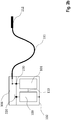
- Fig. 2a shows the interconnection of the subunits 100 and 101 as well as the basic structure of such a subunit 100 consisting of: the preferably electrically conductive housing 105 and the connection area (header) 106, the electrical connections from the interior of 105 via hermetic feedthroughs 230 in the Connection area 106 are performed.
- Block 200 representatively summarizes the energy-storing elements.
- 210 is a control unit and contains a communication unit which exchanges information with other subunits or external devices via the transmitting / receiving element 220. This is, for example, an antenna for electromagnetic communication or a piezo element for communication in the ultrasonic range.
- 210 contains a detection unit via which the voltage UAB is analyzed with regard to electrical cardiac activity (sensing).
- Figure 2b shows the alternative structure of the solution according to Fig 1b .
- Fig. 3 illustrates the principle of the synchronized superposition of partial contributions to the total electrical power from the individual subunits Fig. 2 .
- Fig. 4 shows an example of an interconnection of 3 subunits (in general there can be several). Depending on how the electrically conductive housing (or the housing poles) are connected via the control units, different Therapy vectors are set.
- the sub-unit 400 is basically constructed like the sub-units 100 and 101, except that it has the option of connecting 2 (or more) connecting lines 110 and 111.
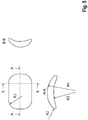
- Fig. 5 shows a preferred geometric shape of the subunits.
- Fig. 6 a to j show preferred implantation arrangements of the system.
- the subunits have at least one connection in order to connect at least one further subunit to the latter via connecting lines 110.
- the energy-storing elements are batteries (primary cells and / or secondary cells) and capacitors or a combination of these and are in Fig. 2 summarized representatively in block 200.
- this block 200 contains means for converting the energy, such as a charging circuit which, controlled by the control unit 210, converts low battery voltages into high therapy voltages.
- Block 200 also contains switches (therapy switches) which, controlled by the control unit, switch on the therapy voltage (partial amount) of the application accordingly. So in the example Fig. 4 this voltage can be switched on between the contact points A1 and A2, A1 and B or A2 and B by setting the switch accordingly.
- the sub-units are connected to one another and synchronized in such a way that the therapy voltage results from the summation of the partial voltages generated by the individual sub-units.
- Fig. 3 illustrates an example of this.
- the sub-units are connected to one another and synchronized in such a way that the therapy current results from the summation of the partial currents generated by the individual sub-units.
- the connection line contains more than just one conductor.
- One of the sub-units is implemented or programmed / configured as a master, the other as a slave
- At least the subunit working as a master has a detection unit (including sensing unit) that derives the need for therapy delivery from the analysis of intracorporeal signals.
- the sensing unit and the detection unit also have access to the measurement voltage UAB (sensing signals) via their connection to the block 200.
- An embodiment according to the invention provides that several or all of the subunits exercise detection, the first taking on the role of the master that makes the detection decision.
- the sub-unit that has become the master puts the other sub-units in the slave role
- the sub-units each contain a control unit for triggering the therapy command.
- the sub-units each contain a communication unit i.a. for sending and receiving the therapy command (the communication information in this case is the therapy command). Transmission and reception are also to be understood as galvanic coupling.
- the subunit working as a master forwards the therapy command both to its own therapy unit (implemented by block 200) and to the slave subunits
- the therapy command encodes both the time of therapy delivery and the polarity and duration for which the partial energies of the individual subunits are switched on. This ensures that the partial contributions of the individual subunits are superimposed synchronously and with the correct sign (see the example in Fig. 3 ). The synchronization takes place with an accuracy of ⁇ 5ms.
- the sub-units have devices for measuring time with an accuracy of better than 5 ms, ie clocks that have knowledge of the absolute time and / or can measure time intervals. If the master recognizes the need to deliver therapy, he can alternatively the other listed methods plan the delivery of the therapy for a certain time (all subunits activate their partial contribution synchronously at the time) or plan with a delay by a programmed duration relative to a certain time. Such a point in time can be, for example, the synchronous command to start the loading process.
- the clocks are able to synchronize with external clocks (e.g. radio clock). Alternatively, the clocks only synchronize within the implanted system. The clocks are synchronized either event-controlled at the time of detection or regularly at intervals that ensure an accuracy of better than 5 ms.
- the subunits have an electrode pole that is galvanically coupled to the tissue and is preferably attached to the housing of the subunit (housing pole). In a preferred embodiment, this is the housing of the respective sub-unit itself, which is then implemented as electrically conductive (e.g. metallic).
- This electrode pole can optionally be switched on for the therapy delivery.
- the therapy command coming from the master subunit also encodes this information as to whether it should be switched on.
- This electrode pole (housing pole) is optionally also used for sensing.
- additional electrode poles for the sensing function are accommodated on the connecting line between the subunits and are connected to the sensing / detection units.
- Signals from sensing electrodes that are only connected to slave subunits are processed by the sensing / detection unit of the respective slave subunit and the result is transmitted to the master subunit via the communication unit.
- the communication links between the sub-units are bidirectional.
- a feedback is sent to the master with regard to the progress of the loading process so that it is ensured that the command to deliver therapy (i.e. synchronous provision of the partial amounts) is only given when all subunits have completed the loading process.
- the sensing / detection unit is protected by circuit breakers from overvoltages as a result of therapy delivery from its own or other subunits of the system. These switches are opened by the control unit shortly before therapy is delivered and then closed again.
- the sensing / detection unit can also be protected against overvoltages (also in the case of external defibrillation) by means of passive protective measures.
- protective diodes are used in one embodiment.
- the subunits have devices for discharging the electrode potentials, e.g. designed as a short-circuit switch.
- the communication between the sub-units takes place galvanically in one of the versions.
- This communication signal is preferably perceived and processed by the sensing unit.
- the following solutions are provided for galvanic communication:
- the circuit is completed via a pair of such connections.
- the pace and sense channels are used for galvanic synchronization, as is the case with conventional ICDs, for example for the atrium and ventricle.
- the connecting conductor only contains the potential connector.
- the circuit for communication is closed via the body.
- the invention provides the following realizations: An alternating current is fed into this circuit, the frequency and amplitude of which does not have a stimulating effect (neither for muscles, nerves nor heart).
- the frequency is> 1kHz and the amplitude ⁇ 1mA.
- these values are individual programmable.
- This alternating current carries the communication information.
- the modulation takes place via a method that is free of mean values (i.e. no DC signals pass through the body).
- Preferred modulation methods are frequency modulation, pulse width modulation, and possibly also amplitude modulation.
- Pulses are fed into this circuit.
- the information is encoded using the pulse width and pulse spacing.
- the pulse width is preferably less than 10 ms (particularly preferably ⁇ 2 ms), the pulse interval over 20 ms (particularly preferably> 80 ms).
- One implementation option uses subliminal pulses that do not stimulate muscles, nerves or the heart
- a predetermined pattern pulse widths, pulse intervals that are defined by design or programming.
- the slave subunit still triggers, but this partial amount does not reach the body because the subunits are connected in series (the circuit in the master remains open).
- a special design provides that such a pulse is the therapy pulse itself.
- the master releases his partial amount while the slave units still have the therapy switch open.
- the circuit initially only closes via the sensing units of the slaves. These perceive the therapy pulse of the master and, if a programmable amplitude threshold is exceeded, also activate their partial contributions with a reaction time of ⁇ 5ms.
- Electromagnetic communication or radio frequency communication enables data and information to be exchanged between the units (100, 101) independently of the galvanic connections (110) and at a much higher speed and, as a result, shorter response times.
- the MICS band radio system included as standard in the units is used for electromagnetic communication.
- the electromagnetic communication in both units is only activated when necessary: Activation for every detection that leads to therapy or shock delivery (e.g. during the charging process) Detection message between the units via the bifilar connection (110) If the ventricular or atrial pace / sense channel is used as the bifilar connection, a signal corresponding to the detection criterion is stimulated.
- the electromagnetic communication is activated periodically or by appointment, e.g. for status or data exchange, for testing the connection, etc.
- the unit to detect first acts as the master for initiating therapy via electromagnetic communication.
- communication between the subunits takes place mechanically / acoustically, in particular in the area of ultrasound
- the IEGM / EKG perceived by the therapy system is triggered according to the invention.
- in order to minimize interference only limited frequency ranges are evaluated and / or morphological features of the IEGM / EKG are used.
- the implantable system has communication options to other implanted systems such as pacemaker systems (in particular ILP), monitoring systems (e.g. loop recorders) and sensors (e.g. blood pressure sensors) as well as to external devices (e.g. for programming, data transmission).
- the control unit 210 also sends therapy commands to pacemaker systems integrated in the therapy concept (e.g. postshock pacing or ATP), or receives information from these devices for the purpose of extended sensing (i.e. more reliable rhythm recognition, discrimination of the tachycardial jump, evaluation of the hemodynamic relevance of arrhythmias using pressure signals).
- the geometric shape of the sub-units is designed so that it adapts as best as possible to the physiological shape of the thorax (rib curvature), is not thick and minimizes pressure points.
- a realization is exemplified in Fig. 5 shown.
- the housing is preferably designed in the shape of a spoon and is dimensioned such that the length and / or width dimension is at least 5 times greater than the thickness dimension.
- the radii of the circumferential contour are at least R1> 5mm.
- the radii of the cross-sectional contour are at least R1> 1mm.
- the radii of the spoon-shaped curvature are at least R4> 30mm.
- the concave curvature described by R3 is less or at most as pronounced as that described by R4. In a preferred embodiment, R3 is also ⁇ 1000mm.
- the connecting line 110 between the sub-units and the line 111 are designed according to the invention as follows:
- the insulation is a biocompatible material, preferably silicone or polyurethane or a combination of both
- the insulation represents the lead body and has at least one lumen through which the potential connector is passed.
- the potential connector consists of electrically highly conductive wires (preferably DFT wire).
- the potential connector is also insulated and this material slides well in the lumen.
- the lead body and has more than one lumen, each lumen leading part of the wires of the potential connector (redundancy to increase reliability). These wires are brought together at the ends of the cable to the respective connector.
- the lumens in the lead body are helically twisted in order to minimize mechanical stresses when bending.
- the line body has support structures for reinforcement against crushing loads. These structures are designed as an intermediate layer concentric to the line cross-section, with the potential connectors running inside
- the materials of the support structures are preferably themselves biocompatible and, for example, metal fibers, aramid fibers or silicones with a higher Shore hardness
- the support structures are designed as a braid or as rings distributed over the length (structure like a windpipe)
- the device according to the invention is preferably implanted as in FIG Fig. 1 a and b as well as Fig. 6 . A to j and explained below.
- FIG. 6a Abdomen Device 1 is located in the abdomen.
- the cable is tunneled past the xiphoid via the sternum to device 2, which is located at a typical ICD location below the collarbone.
- Figure 6b Abdomen and sides of the rib cage
- the device 1 is located in the abdomen.
- a cable is routed subcutaneously next to the xiphoid to the device 2, which is arranged to the side of the chest.
- FIG. 6c Substernal arrangement Device 1 is elongated, very thin, and is placed under the sternum.
- the cable is either tunneled through the intercostal space to the device 2, as shown in the picture, or it leaves the chest near the xiphoid in order to get to the device 2 on the left side of the chest.
- Fig. 6d Sternal arrangement Device 1 has an elongated, very flat shape and is placed on the sternum. The cable is passed subcutaneously outside the chest to the side of the device 2.
- Intercostal arrangement Devices 1 and 2 are narrow and connected subcutaneously but outside the chest with a cable. They are placed between a pair of ribs in the intercostal space. It is also conceivable that one or both devices are wider and extend over several intercostal gaps.
- Fig. 6f Rib cage Both devices sit subcutaneously, possibly submuscularly outside the chest. They are connected to one another by a cable that runs across the sternum.
- Fig. 6g Flat design with integrated application Devices 1 and 2 are very flat and ergonomically designed and integrated in a flat band that is implanted subcutaneously on the chest.
- Fig. 6h Possible implementation with 3 devices Two devices are implanted subcutaneously but outside the chest and one in the abdomen. Every device has the potential to shock.
- the shock vector can be set variably.
- a sensible arrangement can be: shock from the abdominal cavity parallel to the other two devices.
- FIG. 6i Chest strap
- the system consisting of at least 2 devices, is integrated into a belt or a vest.
- This form of implementation is used for the temporary use of a cardioverter system.
- Fig. 6j Epicardial execution In this version, a system consisting of 2 very thin, ergonomically pre-bent devices is placed on the epicardium.
- the solution according to the invention enables the implementation of an S-ICD system based on conventional, more economical implant technology.
- the functionality can be implemented through software adaptation without the need to develop and manufacture new hardware.
- the volume to be implanted is distributed and is less bulky than conventional S-ICDs (improved wearing comfort).
Landscapes
- Health & Medical Sciences (AREA)
- Life Sciences & Earth Sciences (AREA)
- Cardiology (AREA)
- Animal Behavior & Ethology (AREA)
- Public Health (AREA)
- Veterinary Medicine (AREA)
- Biomedical Technology (AREA)
- Engineering & Computer Science (AREA)
- Heart & Thoracic Surgery (AREA)
- General Health & Medical Sciences (AREA)
- Radiology & Medical Imaging (AREA)
- Nuclear Medicine, Radiotherapy & Molecular Imaging (AREA)
- Biophysics (AREA)
- Physics & Mathematics (AREA)
- Pathology (AREA)
- Medical Informatics (AREA)
- Molecular Biology (AREA)
- Surgery (AREA)
- Electrotherapy Devices (AREA)
Claims (13)
- Ensemble de thérapie électrique pour un patient, où l'ensemble est prévu pour générer au moins une tension thérapeutique électrique qui agit au niveau d'un emplacement de thérapie dans ou sur le corps du patient,
où l'ensemble comprend au moins une première et une deuxième sous-unité, et chaque sous-unité présente au moins un accumulateur d'énergie,
où chaque quantité d'énergie pouvant être stockée par un accumulateur d'énergie individuel est inférieure à la quantité d'énergie nécessaire pour la génération de la tension thérapeutique électrique,
où chaque sous-unité présente au moins un des composants suivants :- une unité de détection pour la détection de paramètres corporels,- une unité de thérapie pour la génération et/ou la délivrance d'une tension électrique pour la thérapie électrique,- une unité de commande, et/ou- une unité de communication,caractérisé en ce que
l'ensemble est prévu de sorte qu'une sous-unité prend un rôle de maître en ce qui concerne la génération et/ou la délivrance d'une tension électrique, et l'au moins une sous-unité restante prend un rôle d'esclave, de sorte que l'au moins une sous-unité se trouvant dans le rôle d'esclave oriente en ce qui concerne le moment de la délivrance de la thérapie, et/ou la polarité de la délivrance de la thérapie, et/ou la durée de la délivrance de la thérapie, au niveau de la sous-unité dans le rôle de maître. - Ensemble selon la revendication 1, dans lequel les au moins une première et une deuxième sous-unité sont prévues pour générer une tension électrique par l'énergie provenant de l'accumulateur d'énergie, et où l'ensemble est prévu pour générer la tension thérapeutique électrique en ce que les tensions générées par l'au moins une première et une deuxième sous-unité sont superposées.
- Ensemble selon au moins une des revendications 1 ou 2, dans lequel la première sous-unité est disposée dans un premier boîtier extérieur, et la deuxième sous-unité est disposée dans un deuxième boîtier extérieur.
- Ensemble selon la revendication 2, dans lequel les au moins une première et une deuxième sous-unité sont disposées dans un boîtier extérieur commun.
- Ensemble selon au moins une des revendications 2 à 4, dans lequel les tensions générées par les au moins deux sous-unités sont superposées de sorte que l'amplitude de la tension superposée est supérieure à l'amplitude d'une tension générée par une sous-unité.
- Ensemble selon au moins une des revendications précédentes, dans lequel les tensions générées par les au moins deux sous-unités sont superposées de sorte que les tensions sont essentiellement synchronisées en phases au niveau de l'emplacement de thérapie.
- Ensemble selon au moins une des revendications précédentes, dans lequel chaque sous-unité est prévue pour communiquer au moins avec une autre sous-unité, où la communication a lieu de manière galvanique, électromagnétique, optique, mécanique et/ou acoustique.
- Ensemble selon au moins une des revendications précédentes, dans lequel au moins une sous-unité présente une unité de commande, où l'unité de commande est conçue pour délivrer une commande de thérapie, où la commande de thérapie porte des informations concernant au moins un des paramètres suivants :- des indications concernant la phase de la tension respective fournie par la sous-unité,- le moment de la délivrance de la thérapie,- la polarité de la délivrance de la thérapie, et/ou- la durée de la délivrance de la thérapie sur la sous-unité respective.
- Ensemble selon au moins une des revendications précédentes, dans lequel chaque sous-unité présente au moins une unité de détection pour la détection de paramètres corporels et dans lequel une sous-unité prend un rôle de maître qui détecte un paramètre corporel nécessitant une thérapie en premier lieu, c'est-à-dire avant toutes les autres sous-unités.
- Ensemble selon au moins une des revendications précédentes, où l'ensemble présente au moins un ensemble de liaison, où les au moins deux sous-unités sont reliées électriquement par l'ensemble de liaison et où l'ensemble de liaison est isolé électriquement du corps du patient.
- Ensemble selon la revendication 10, dans lequel les au moins deux sous-unités sont reliées en série, en anti série, en parallèle ou en forme d'étoile par le biais de l'ensemble de liaison.
- Ensemble selon la revendication 10, où l'ensemble est conçu pour générer une synchronisation de phase essentielle des tensions générées par les au moins deux sous-unités sur l'emplacement de thérapie par le biais de l'au moins un ensemble de liaison.
- Ensemble selon au moins une des revendications précédentes, dans lequel les au moins deux sous-unités- comprennent respectivement une batterie, et/ou- comprennent respectivement un condensateur, et/ou- représentent respectivement un défibrillateur-cardioverteur implantable en sous cutané (sICD).
Applications Claiming Priority (1)
| Application Number | Priority Date | Filing Date | Title |
|---|---|---|---|
| DE102017125044.1A DE102017125044A1 (de) | 2017-10-26 | 2017-10-26 | Vorrichtung zur Hochspannungstherapie |
Publications (2)
| Publication Number | Publication Date |
|---|---|
| EP3476432A1 EP3476432A1 (fr) | 2019-05-01 |
| EP3476432B1 true EP3476432B1 (fr) | 2020-12-16 |
Family
ID=63878508
Family Applications (1)
| Application Number | Title | Priority Date | Filing Date |
|---|---|---|---|
| EP18200923.3A Active EP3476432B1 (fr) | 2017-10-26 | 2018-10-17 | Dispositif de thérapie de haute tension |
Country Status (6)
| Country | Link |
|---|---|
| US (1) | US20190126054A1 (fr) |
| EP (1) | EP3476432B1 (fr) |
| JP (1) | JP2019076729A (fr) |
| CN (1) | CN109701159A (fr) |
| DE (1) | DE102017125044A1 (fr) |
| SG (1) | SG10201808618XA (fr) |
Citations (1)
| Publication number | Priority date | Publication date | Assignee | Title |
|---|---|---|---|---|
| WO2007068284A1 (fr) * | 2005-12-12 | 2007-06-21 | Synergio Ag | Dispositif intracardiaque, système et procédés |
Family Cites Families (14)
| Publication number | Priority date | Publication date | Assignee | Title |
|---|---|---|---|---|
| US6091989A (en) * | 1998-04-08 | 2000-07-18 | Swerdlow; Charles D. | Method and apparatus for reduction of pain from electric shock therapies |
| US20050107833A1 (en) * | 2003-11-13 | 2005-05-19 | Freeman Gary A. | Multi-path transthoracic defibrillation and cardioversion |
| WO2006061725A2 (fr) * | 2004-12-08 | 2006-06-15 | Koninklijke Philips Electronics N.V. | Defibrillateur externe automatique a deux batteries |
| US8391990B2 (en) * | 2005-05-18 | 2013-03-05 | Cardiac Pacemakers, Inc. | Modular antitachyarrhythmia therapy system |
| EP2471451A1 (fr) * | 2005-10-14 | 2012-07-04 | Nanostim, Inc. | Stimulateur cardiaque sans fil et système |
| US8612020B2 (en) * | 2008-10-31 | 2013-12-17 | Medtronic, Inc. | Implantable therapeutic nerve stimulator |
| US20120150247A1 (en) * | 2010-12-08 | 2012-06-14 | Meier Giovanni C | Battery pack topology |
| US8781583B2 (en) * | 2011-01-19 | 2014-07-15 | Medtronic, Inc. | Vagal stimulation |
| EP2478935B1 (fr) * | 2011-01-21 | 2017-08-23 | NeuroCardiac Innovations, LLC | Dispositifs cardiaques implantables avec unité d'orientation de corps |
| US9907972B2 (en) * | 2011-01-21 | 2018-03-06 | Neurocardiac Innovations, Llc | Implantable cardiac devices and methods with body orientation unit |
| EP2520332A1 (fr) * | 2011-05-05 | 2012-11-07 | Magnetic Pacing Technologies GmbH | Dispositif de stimulation implantable pour défribilisation et stimulation |
| US20140214105A1 (en) * | 2013-01-31 | 2014-07-31 | Medtronic, Inc. | Tandem series coupled implantable subcutaneous cardioverter defibrillators and method |
| US8744572B1 (en) * | 2013-01-31 | 2014-06-03 | Medronic, Inc. | Systems and methods for leadless pacing and shock therapy |
| WO2016149623A1 (fr) * | 2015-03-18 | 2016-09-22 | Cardio Thrive, Inc. | Système thérapeutique et procédé associé faisant appel à une forme d'onde à impulsion biphasique ou multiphasique |
-
2017
- 2017-10-26 DE DE102017125044.1A patent/DE102017125044A1/de not_active Withdrawn
-
2018
- 2018-10-01 SG SG10201808618XA patent/SG10201808618XA/en unknown
- 2018-10-12 CN CN201811188169.9A patent/CN109701159A/zh active Pending
- 2018-10-17 EP EP18200923.3A patent/EP3476432B1/fr active Active
- 2018-10-25 JP JP2018200481A patent/JP2019076729A/ja active Pending
- 2018-10-26 US US16/171,613 patent/US20190126054A1/en not_active Abandoned
Patent Citations (1)
| Publication number | Priority date | Publication date | Assignee | Title |
|---|---|---|---|---|
| WO2007068284A1 (fr) * | 2005-12-12 | 2007-06-21 | Synergio Ag | Dispositif intracardiaque, système et procédés |
Also Published As
| Publication number | Publication date |
|---|---|
| EP3476432A1 (fr) | 2019-05-01 |
| CN109701159A (zh) | 2019-05-03 |
| US20190126054A1 (en) | 2019-05-02 |
| SG10201808618XA (en) | 2019-05-30 |
| DE102017125044A1 (de) | 2019-05-02 |
| JP2019076729A (ja) | 2019-05-23 |
Similar Documents
| Publication | Publication Date | Title |
|---|---|---|
| US11291834B2 (en) | Subcutaneous implantation medical device with multiple parasternal-anterior electrodes | |
| DE69734454T2 (de) | Vorhofdefibrillationsanordnung mit zwei stromwegen | |
| EP2060299B1 (fr) | Stimulateur cardiaque bi-ventriculaire | |
| US7917218B2 (en) | Filtering capacitor feedthrough assembly | |
| DE60019881T2 (de) | Implantierbare aktive Vorrichtung des Typs multisite mit Mitteln zum Resynchronisieren der Ventrikeln | |
| US20150088155A1 (en) | Mechanical configurations for a multi-site leadless pacemaker | |
| WO2006106132A1 (fr) | Dispositif electromedical implantable ou extracorporel pour le traitement d'organes et la surveillance d'organes et procede de traitement therapeutique d'organes | |
| CN106255529A (zh) | 触发式起搏系统 | |
| EP3278836B1 (fr) | Implant électromédical comprenant un passage électrique | |
| CN107567304A (zh) | 用于检测高能量心脏电刺激之后的固有去极化的方法和装置 | |
| DE202007018529U1 (de) | Implantierbarer Funkfrequenzdefibrillator R.F. | |
| EP2603285B1 (fr) | Cardioverteur pour éliminer la fibrillation auriculaire | |
| EP3476432B1 (fr) | Dispositif de thérapie de haute tension | |
| DE69635958T2 (de) | Vorrichtung zur zeitlichen elektrischen erzwingung des kardialen ausstosses, als sicherungssystem für tachykardie-patienten | |
| DE60012909T2 (de) | Kardiale defibrillierung | |
| DE202007018531U1 (de) | Zweikammerstimulationsspulen für die Vorhofdefibrillation und Kammerstimulation | |
| DE19632705A1 (de) | Vorrichtung zur Stimulation der Corpora Cavernosi Penis | |
| EP2146777A1 (fr) | Système de stimulation électrique de muscles ou de nerfs | |
| EP2865415B1 (fr) | Unité de perception pour un stimulateur tissulaire | |
| EP3586913A1 (fr) | Dispositif d'activation des structures cellulaires au moyen de l'énergie électromagnétique | |
| EP3854449A1 (fr) | Appareil médical pouvant être implanté pour stimuler un c ur humain ou animal | |
| US20200306540A1 (en) | Systems and methods for making and using a low-profile control module for an electrical stimulation system | |
| WO2020254193A1 (fr) | Procédé pouvant être mis en œuvre pour faire fonctionner un stimulateur cardiaque |
Legal Events
| Date | Code | Title | Description |
|---|---|---|---|
| PUAI | Public reference made under article 153(3) epc to a published international application that has entered the european phase |
Free format text: ORIGINAL CODE: 0009012 |
|
| STAA | Information on the status of an ep patent application or granted ep patent |
Free format text: STATUS: THE APPLICATION HAS BEEN PUBLISHED |
|
| AK | Designated contracting states |
Kind code of ref document: A1 Designated state(s): AL AT BE BG CH CY CZ DE DK EE ES FI FR GB GR HR HU IE IS IT LI LT LU LV MC MK MT NL NO PL PT RO RS SE SI SK SM TR |
|
| AX | Request for extension of the european patent |
Extension state: BA ME |
|
| STAA | Information on the status of an ep patent application or granted ep patent |
Free format text: STATUS: REQUEST FOR EXAMINATION WAS MADE |
|
| 17P | Request for examination filed |
Effective date: 20191028 |
|
| RBV | Designated contracting states (corrected) |
Designated state(s): AL AT BE BG CH CY CZ DE DK EE ES FI FR GB GR HR HU IE IS IT LI LT LU LV MC MK MT NL NO PL PT RO RS SE SI SK SM TR |
|
| STAA | Information on the status of an ep patent application or granted ep patent |
Free format text: STATUS: EXAMINATION IS IN PROGRESS |
|
| 17Q | First examination report despatched |
Effective date: 20200430 |
|
| GRAP | Despatch of communication of intention to grant a patent |
Free format text: ORIGINAL CODE: EPIDOSNIGR1 |
|
| STAA | Information on the status of an ep patent application or granted ep patent |
Free format text: STATUS: GRANT OF PATENT IS INTENDED |
|
| RIC1 | Information provided on ipc code assigned before grant |
Ipc: A61B 5/0245 20060101ALN20200622BHEP Ipc: A61N 1/39 20060101AFI20200622BHEP |
|
| INTG | Intention to grant announced |
Effective date: 20200728 |
|
| GRAS | Grant fee paid |
Free format text: ORIGINAL CODE: EPIDOSNIGR3 |
|
| GRAA | (expected) grant |
Free format text: ORIGINAL CODE: 0009210 |
|
| STAA | Information on the status of an ep patent application or granted ep patent |
Free format text: STATUS: THE PATENT HAS BEEN GRANTED |
|
| AK | Designated contracting states |
Kind code of ref document: B1 Designated state(s): AL AT BE BG CH CY CZ DE DK EE ES FI FR GB GR HR HU IE IS IT LI LT LU LV MC MK MT NL NO PL PT RO RS SE SI SK SM TR |
|
| REG | Reference to a national code |
Ref country code: GB Ref legal event code: FG4D Free format text: NOT ENGLISH |
|
| REG | Reference to a national code |
Ref country code: IE Ref legal event code: FG4D Free format text: LANGUAGE OF EP DOCUMENT: GERMAN |
|
| REG | Reference to a national code |
Ref country code: DE Ref legal event code: R096 Ref document number: 502018003314 Country of ref document: DE |
|
| REG | Reference to a national code |
Ref country code: AT Ref legal event code: REF Ref document number: 1345049 Country of ref document: AT Kind code of ref document: T Effective date: 20210115 |
|
| PG25 | Lapsed in a contracting state [announced via postgrant information from national office to epo] |
Ref country code: NO Free format text: LAPSE BECAUSE OF FAILURE TO SUBMIT A TRANSLATION OF THE DESCRIPTION OR TO PAY THE FEE WITHIN THE PRESCRIBED TIME-LIMIT Effective date: 20210316 Ref country code: GR Free format text: LAPSE BECAUSE OF FAILURE TO SUBMIT A TRANSLATION OF THE DESCRIPTION OR TO PAY THE FEE WITHIN THE PRESCRIBED TIME-LIMIT Effective date: 20210317 Ref country code: FI Free format text: LAPSE BECAUSE OF FAILURE TO SUBMIT A TRANSLATION OF THE DESCRIPTION OR TO PAY THE FEE WITHIN THE PRESCRIBED TIME-LIMIT Effective date: 20201216 Ref country code: RS Free format text: LAPSE BECAUSE OF FAILURE TO SUBMIT A TRANSLATION OF THE DESCRIPTION OR TO PAY THE FEE WITHIN THE PRESCRIBED TIME-LIMIT Effective date: 20201216 |
|
| REG | Reference to a national code |
Ref country code: NL Ref legal event code: MP Effective date: 20201216 |
|
| PG25 | Lapsed in a contracting state [announced via postgrant information from national office to epo] |
Ref country code: BG Free format text: LAPSE BECAUSE OF FAILURE TO SUBMIT A TRANSLATION OF THE DESCRIPTION OR TO PAY THE FEE WITHIN THE PRESCRIBED TIME-LIMIT Effective date: 20210316 Ref country code: LV Free format text: LAPSE BECAUSE OF FAILURE TO SUBMIT A TRANSLATION OF THE DESCRIPTION OR TO PAY THE FEE WITHIN THE PRESCRIBED TIME-LIMIT Effective date: 20201216 Ref country code: SE Free format text: LAPSE BECAUSE OF FAILURE TO SUBMIT A TRANSLATION OF THE DESCRIPTION OR TO PAY THE FEE WITHIN THE PRESCRIBED TIME-LIMIT Effective date: 20201216 |
|
| PG25 | Lapsed in a contracting state [announced via postgrant information from national office to epo] |
Ref country code: HR Free format text: LAPSE BECAUSE OF FAILURE TO SUBMIT A TRANSLATION OF THE DESCRIPTION OR TO PAY THE FEE WITHIN THE PRESCRIBED TIME-LIMIT Effective date: 20201216 Ref country code: NL Free format text: LAPSE BECAUSE OF FAILURE TO SUBMIT A TRANSLATION OF THE DESCRIPTION OR TO PAY THE FEE WITHIN THE PRESCRIBED TIME-LIMIT Effective date: 20201216 |
|
| REG | Reference to a national code |
Ref country code: LT Ref legal event code: MG9D |
|
| PG25 | Lapsed in a contracting state [announced via postgrant information from national office to epo] |
Ref country code: LT Free format text: LAPSE BECAUSE OF FAILURE TO SUBMIT A TRANSLATION OF THE DESCRIPTION OR TO PAY THE FEE WITHIN THE PRESCRIBED TIME-LIMIT Effective date: 20201216 Ref country code: PT Free format text: LAPSE BECAUSE OF FAILURE TO SUBMIT A TRANSLATION OF THE DESCRIPTION OR TO PAY THE FEE WITHIN THE PRESCRIBED TIME-LIMIT Effective date: 20210416 Ref country code: SK Free format text: LAPSE BECAUSE OF FAILURE TO SUBMIT A TRANSLATION OF THE DESCRIPTION OR TO PAY THE FEE WITHIN THE PRESCRIBED TIME-LIMIT Effective date: 20201216 Ref country code: RO Free format text: LAPSE BECAUSE OF FAILURE TO SUBMIT A TRANSLATION OF THE DESCRIPTION OR TO PAY THE FEE WITHIN THE PRESCRIBED TIME-LIMIT Effective date: 20201216 Ref country code: SM Free format text: LAPSE BECAUSE OF FAILURE TO SUBMIT A TRANSLATION OF THE DESCRIPTION OR TO PAY THE FEE WITHIN THE PRESCRIBED TIME-LIMIT Effective date: 20201216 Ref country code: EE Free format text: LAPSE BECAUSE OF FAILURE TO SUBMIT A TRANSLATION OF THE DESCRIPTION OR TO PAY THE FEE WITHIN THE PRESCRIBED TIME-LIMIT Effective date: 20201216 Ref country code: CZ Free format text: LAPSE BECAUSE OF FAILURE TO SUBMIT A TRANSLATION OF THE DESCRIPTION OR TO PAY THE FEE WITHIN THE PRESCRIBED TIME-LIMIT Effective date: 20201216 |
|
| PG25 | Lapsed in a contracting state [announced via postgrant information from national office to epo] |
Ref country code: PL Free format text: LAPSE BECAUSE OF FAILURE TO SUBMIT A TRANSLATION OF THE DESCRIPTION OR TO PAY THE FEE WITHIN THE PRESCRIBED TIME-LIMIT Effective date: 20201216 |
|
| REG | Reference to a national code |
Ref country code: DE Ref legal event code: R097 Ref document number: 502018003314 Country of ref document: DE |
|
| PG25 | Lapsed in a contracting state [announced via postgrant information from national office to epo] |
Ref country code: IS Free format text: LAPSE BECAUSE OF FAILURE TO SUBMIT A TRANSLATION OF THE DESCRIPTION OR TO PAY THE FEE WITHIN THE PRESCRIBED TIME-LIMIT Effective date: 20210416 |
|
| PLBE | No opposition filed within time limit |
Free format text: ORIGINAL CODE: 0009261 |
|
| STAA | Information on the status of an ep patent application or granted ep patent |
Free format text: STATUS: NO OPPOSITION FILED WITHIN TIME LIMIT |
|
| PG25 | Lapsed in a contracting state [announced via postgrant information from national office to epo] |
Ref country code: IT Free format text: LAPSE BECAUSE OF FAILURE TO SUBMIT A TRANSLATION OF THE DESCRIPTION OR TO PAY THE FEE WITHIN THE PRESCRIBED TIME-LIMIT Effective date: 20201216 Ref country code: AL Free format text: LAPSE BECAUSE OF FAILURE TO SUBMIT A TRANSLATION OF THE DESCRIPTION OR TO PAY THE FEE WITHIN THE PRESCRIBED TIME-LIMIT Effective date: 20201216 |
|
| 26N | No opposition filed |
Effective date: 20210917 |
|
| PG25 | Lapsed in a contracting state [announced via postgrant information from national office to epo] |
Ref country code: DK Free format text: LAPSE BECAUSE OF FAILURE TO SUBMIT A TRANSLATION OF THE DESCRIPTION OR TO PAY THE FEE WITHIN THE PRESCRIBED TIME-LIMIT Effective date: 20201216 |
|
| PG25 | Lapsed in a contracting state [announced via postgrant information from national office to epo] |
Ref country code: ES Free format text: LAPSE BECAUSE OF FAILURE TO SUBMIT A TRANSLATION OF THE DESCRIPTION OR TO PAY THE FEE WITHIN THE PRESCRIBED TIME-LIMIT Effective date: 20201216 |
|
| PG25 | Lapsed in a contracting state [announced via postgrant information from national office to epo] |
Ref country code: SI Free format text: LAPSE BECAUSE OF FAILURE TO SUBMIT A TRANSLATION OF THE DESCRIPTION OR TO PAY THE FEE WITHIN THE PRESCRIBED TIME-LIMIT Effective date: 20201216 |
|
| PG25 | Lapsed in a contracting state [announced via postgrant information from national office to epo] |
Ref country code: IS Free format text: LAPSE BECAUSE OF FAILURE TO SUBMIT A TRANSLATION OF THE DESCRIPTION OR TO PAY THE FEE WITHIN THE PRESCRIBED TIME-LIMIT Effective date: 20210416 |
|
| REG | Reference to a national code |
Ref country code: BE Ref legal event code: MM Effective date: 20211031 |
|
| PG25 | Lapsed in a contracting state [announced via postgrant information from national office to epo] |
Ref country code: MC Free format text: LAPSE BECAUSE OF FAILURE TO SUBMIT A TRANSLATION OF THE DESCRIPTION OR TO PAY THE FEE WITHIN THE PRESCRIBED TIME-LIMIT Effective date: 20201216 |
|
| PG25 | Lapsed in a contracting state [announced via postgrant information from national office to epo] |
Ref country code: LU Free format text: LAPSE BECAUSE OF NON-PAYMENT OF DUE FEES Effective date: 20211017 Ref country code: BE Free format text: LAPSE BECAUSE OF NON-PAYMENT OF DUE FEES Effective date: 20211031 |
|
| PG25 | Lapsed in a contracting state [announced via postgrant information from national office to epo] |
Ref country code: FR Free format text: LAPSE BECAUSE OF NON-PAYMENT OF DUE FEES Effective date: 20211031 |
|
| PGFP | Annual fee paid to national office [announced via postgrant information from national office to epo] |
Ref country code: IE Payment date: 20221021 Year of fee payment: 5 Ref country code: DE Payment date: 20221025 Year of fee payment: 5 |
|
| PGFP | Annual fee paid to national office [announced via postgrant information from national office to epo] |
Ref country code: CH Payment date: 20221027 Year of fee payment: 5 |
|
| GBPC | Gb: european patent ceased through non-payment of renewal fee |
Effective date: 20221017 |
|
| PG25 | Lapsed in a contracting state [announced via postgrant information from national office to epo] |
Ref country code: CY Free format text: LAPSE BECAUSE OF FAILURE TO SUBMIT A TRANSLATION OF THE DESCRIPTION OR TO PAY THE FEE WITHIN THE PRESCRIBED TIME-LIMIT Effective date: 20201216 |
|
| PG25 | Lapsed in a contracting state [announced via postgrant information from national office to epo] |
Ref country code: HU Free format text: LAPSE BECAUSE OF FAILURE TO SUBMIT A TRANSLATION OF THE DESCRIPTION OR TO PAY THE FEE WITHIN THE PRESCRIBED TIME-LIMIT; INVALID AB INITIO Effective date: 20181017 |
|
| PG25 | Lapsed in a contracting state [announced via postgrant information from national office to epo] |
Ref country code: GB Free format text: LAPSE BECAUSE OF NON-PAYMENT OF DUE FEES Effective date: 20221017 |
|
| PG25 | Lapsed in a contracting state [announced via postgrant information from national office to epo] |
Ref country code: MK Free format text: LAPSE BECAUSE OF FAILURE TO SUBMIT A TRANSLATION OF THE DESCRIPTION OR TO PAY THE FEE WITHIN THE PRESCRIBED TIME-LIMIT Effective date: 20201216 |