EP3476266A1 - Roboterstaubsauger, der einen entfernbaren handstaubsauger umfasst - Google Patents
Roboterstaubsauger, der einen entfernbaren handstaubsauger umfasst Download PDFInfo
- Publication number
- EP3476266A1 EP3476266A1 EP18202725.0A EP18202725A EP3476266A1 EP 3476266 A1 EP3476266 A1 EP 3476266A1 EP 18202725 A EP18202725 A EP 18202725A EP 3476266 A1 EP3476266 A1 EP 3476266A1
- Authority
- EP
- European Patent Office
- Prior art keywords
- vacuum cleaner
- mobile base
- hand
- held vacuum
- electronic card
- Prior art date
- Legal status (The legal status is an assumption and is not a legal conclusion. Google has not performed a legal analysis and makes no representation as to the accuracy of the status listed.)
- Granted
Links
- 230000000295 complement effect Effects 0.000 claims abstract description 3
- 238000003032 molecular docking Methods 0.000 claims description 25
- 239000000428 dust Substances 0.000 description 8
- 239000008188 pellet Substances 0.000 description 6
- 239000004020 conductor Substances 0.000 description 5
- 238000012423 maintenance Methods 0.000 description 5
- 239000002184 metal Substances 0.000 description 5
- 238000004140 cleaning Methods 0.000 description 3
- 238000000605 extraction Methods 0.000 description 3
- 238000007789 sealing Methods 0.000 description 3
- 238000009423 ventilation Methods 0.000 description 3
- 239000002699 waste material Substances 0.000 description 3
- 230000000694 effects Effects 0.000 description 2
- 230000005540 biological transmission Effects 0.000 description 1
- 238000006073 displacement reaction Methods 0.000 description 1
- WABPQHHGFIMREM-UHFFFAOYSA-N lead(0) Chemical compound [Pb] WABPQHHGFIMREM-UHFFFAOYSA-N 0.000 description 1
- 230000014759 maintenance of location Effects 0.000 description 1
- 230000007257 malfunction Effects 0.000 description 1
- 238000004519 manufacturing process Methods 0.000 description 1
- 238000009827 uniform distribution Methods 0.000 description 1
- 239000011800 void material Substances 0.000 description 1
Images


Classifications
-
- A—HUMAN NECESSITIES
- A47—FURNITURE; DOMESTIC ARTICLES OR APPLIANCES; COFFEE MILLS; SPICE MILLS; SUCTION CLEANERS IN GENERAL
- A47L—DOMESTIC WASHING OR CLEANING; SUCTION CLEANERS IN GENERAL
- A47L9/00—Details or accessories of suction cleaners, e.g. mechanical means for controlling the suction or for effecting pulsating action; Storing devices specially adapted to suction cleaners or parts thereof; Carrying-vehicles specially adapted for suction cleaners
- A47L9/28—Installation of the electric equipment, e.g. adaptation or attachment to the suction cleaner; Controlling suction cleaners by electric means
- A47L9/2836—Installation of the electric equipment, e.g. adaptation or attachment to the suction cleaner; Controlling suction cleaners by electric means characterised by the parts which are controlled
- A47L9/2852—Elements for displacement of the vacuum cleaner or the accessories therefor, e.g. wheels, casters or nozzles
-
- A—HUMAN NECESSITIES
- A47—FURNITURE; DOMESTIC ARTICLES OR APPLIANCES; COFFEE MILLS; SPICE MILLS; SUCTION CLEANERS IN GENERAL
- A47L—DOMESTIC WASHING OR CLEANING; SUCTION CLEANERS IN GENERAL
- A47L5/00—Structural features of suction cleaners
- A47L5/12—Structural features of suction cleaners with power-driven air-pumps or air-compressors, e.g. driven by motor vehicle engine vacuum
- A47L5/22—Structural features of suction cleaners with power-driven air-pumps or air-compressors, e.g. driven by motor vehicle engine vacuum with rotary fans
- A47L5/225—Convertible suction cleaners, i.e. convertible between different types thereof, e.g. from upright suction cleaners to sledge-type suction cleaners
-
- A—HUMAN NECESSITIES
- A47—FURNITURE; DOMESTIC ARTICLES OR APPLIANCES; COFFEE MILLS; SPICE MILLS; SUCTION CLEANERS IN GENERAL
- A47L—DOMESTIC WASHING OR CLEANING; SUCTION CLEANERS IN GENERAL
- A47L5/00—Structural features of suction cleaners
- A47L5/12—Structural features of suction cleaners with power-driven air-pumps or air-compressors, e.g. driven by motor vehicle engine vacuum
- A47L5/22—Structural features of suction cleaners with power-driven air-pumps or air-compressors, e.g. driven by motor vehicle engine vacuum with rotary fans
- A47L5/24—Hand-supported suction cleaners
-
- A—HUMAN NECESSITIES
- A47—FURNITURE; DOMESTIC ARTICLES OR APPLIANCES; COFFEE MILLS; SPICE MILLS; SUCTION CLEANERS IN GENERAL
- A47L—DOMESTIC WASHING OR CLEANING; SUCTION CLEANERS IN GENERAL
- A47L9/00—Details or accessories of suction cleaners, e.g. mechanical means for controlling the suction or for effecting pulsating action; Storing devices specially adapted to suction cleaners or parts thereof; Carrying-vehicles specially adapted for suction cleaners
- A47L9/0081—Means for exhaust-air diffusion; Means for sound or vibration damping
-
- A—HUMAN NECESSITIES
- A47—FURNITURE; DOMESTIC ARTICLES OR APPLIANCES; COFFEE MILLS; SPICE MILLS; SUCTION CLEANERS IN GENERAL
- A47L—DOMESTIC WASHING OR CLEANING; SUCTION CLEANERS IN GENERAL
- A47L9/00—Details or accessories of suction cleaners, e.g. mechanical means for controlling the suction or for effecting pulsating action; Storing devices specially adapted to suction cleaners or parts thereof; Carrying-vehicles specially adapted for suction cleaners
- A47L9/009—Carrying-vehicles; Arrangements of trollies or wheels; Means for avoiding mechanical obstacles
-
- A—HUMAN NECESSITIES
- A47—FURNITURE; DOMESTIC ARTICLES OR APPLIANCES; COFFEE MILLS; SPICE MILLS; SUCTION CLEANERS IN GENERAL
- A47L—DOMESTIC WASHING OR CLEANING; SUCTION CLEANERS IN GENERAL
- A47L9/00—Details or accessories of suction cleaners, e.g. mechanical means for controlling the suction or for effecting pulsating action; Storing devices specially adapted to suction cleaners or parts thereof; Carrying-vehicles specially adapted for suction cleaners
- A47L9/28—Installation of the electric equipment, e.g. adaptation or attachment to the suction cleaner; Controlling suction cleaners by electric means
- A47L9/2857—User input or output elements for control, e.g. buttons, switches or displays
-
- A—HUMAN NECESSITIES
- A47—FURNITURE; DOMESTIC ARTICLES OR APPLIANCES; COFFEE MILLS; SPICE MILLS; SUCTION CLEANERS IN GENERAL
- A47L—DOMESTIC WASHING OR CLEANING; SUCTION CLEANERS IN GENERAL
- A47L9/00—Details or accessories of suction cleaners, e.g. mechanical means for controlling the suction or for effecting pulsating action; Storing devices specially adapted to suction cleaners or parts thereof; Carrying-vehicles specially adapted for suction cleaners
- A47L9/28—Installation of the electric equipment, e.g. adaptation or attachment to the suction cleaner; Controlling suction cleaners by electric means
- A47L9/2868—Arrangements for power supply of vacuum cleaners or the accessories thereof
- A47L9/2873—Docking units or charging stations
-
- A—HUMAN NECESSITIES
- A47—FURNITURE; DOMESTIC ARTICLES OR APPLIANCES; COFFEE MILLS; SPICE MILLS; SUCTION CLEANERS IN GENERAL
- A47L—DOMESTIC WASHING OR CLEANING; SUCTION CLEANERS IN GENERAL
- A47L9/00—Details or accessories of suction cleaners, e.g. mechanical means for controlling the suction or for effecting pulsating action; Storing devices specially adapted to suction cleaners or parts thereof; Carrying-vehicles specially adapted for suction cleaners
- A47L9/32—Handles
- A47L9/322—Handles for hand-supported suction cleaners
-
- B—PERFORMING OPERATIONS; TRANSPORTING
- B25—HAND TOOLS; PORTABLE POWER-DRIVEN TOOLS; MANIPULATORS
- B25J—MANIPULATORS; CHAMBERS PROVIDED WITH MANIPULATION DEVICES
- B25J11/00—Manipulators not otherwise provided for
- B25J11/008—Manipulators for service tasks
- B25J11/0085—Cleaning
-
- B—PERFORMING OPERATIONS; TRANSPORTING
- B25—HAND TOOLS; PORTABLE POWER-DRIVEN TOOLS; MANIPULATORS
- B25J—MANIPULATORS; CHAMBERS PROVIDED WITH MANIPULATION DEVICES
- B25J19/00—Accessories fitted to manipulators, e.g. for monitoring, for viewing; Safety devices combined with or specially adapted for use in connection with manipulators
- B25J19/005—Accessories fitted to manipulators, e.g. for monitoring, for viewing; Safety devices combined with or specially adapted for use in connection with manipulators using batteries, e.g. as a back-up power source
-
- A—HUMAN NECESSITIES
- A47—FURNITURE; DOMESTIC ARTICLES OR APPLIANCES; COFFEE MILLS; SPICE MILLS; SUCTION CLEANERS IN GENERAL
- A47L—DOMESTIC WASHING OR CLEANING; SUCTION CLEANERS IN GENERAL
- A47L2201/00—Robotic cleaning machines, i.e. with automatic control of the travelling movement or the cleaning operation
- A47L2201/02—Docking stations; Docking operations
- A47L2201/022—Recharging of batteries
Definitions
- the present invention relates to the field of vacuum cleaner type cleaning devices and, more particularly, a robot vacuum cleaner which comprises a mobile base incorporating a vacuum cleaner that can be extracted from this base for use by hand in order to suck surfaces not accessible by said robot.
- Suction cleaning robots more commonly known as robot vacuum cleaners, have become commonplace today, allowing them to clean entire surfaces of a home without any user assistance from the moment these surfaces are flat, that is to say on the same level, and that no obstacle prevents access to surfaces to suck. They offer users considerable time savings for other activities.
- the user must therefore still have a hand vacuum, easily manageable and lightweight to allow him to access said raised surfaces and clean them.
- the robot vacuum cleaner comprises a mobile base configured to move in the environment in which it evolves. This mobile base receives a hand vacuum able to suck the waste while remaining in position on said moving base. The vacuum cleaner can be cleared from the base for individual use.
- the suction is carried out either directly by means of the tip of the hand vacuum, such as in documents US5709007A and US2012189507A1 or by means of a mouth on the mobile base which communicates with the nozzle of the hand-held vacuum cleaner, as in the documents CN205083385U , EP0635236B1 , EP2649920A1 and KR20080028219A .
- a brush roll can also be arranged at this mouth of the mobile base to lift the dust before suction, to improve the quality of cleaning, as in documents EP0635236B1 , EP2649920A1 and KR20080028219A .
- a crizlic performance is not optimal, according to these implementations.
- the body of the hand-held vacuum cleaner is attached to the mobile base which incorporates the first battery power supply. Electrical connectors provide a connection of the body of the hand-held vacuum cleaner with the mobile base for its power supply by the first batteries.
- a handle is attached to said body. This handle is electrically connected to the body and incorporates second battery power supply for the autonomous operation of the hand vacuum.
- the mobile base incorporates first power supply batteries for its autonomous operation and the handheld vacuum cleaner includes second power supply batteries for its autonomous operation. Electrical connectors allow the hand-held vacuum to be connected to the mobile base when these elements are assembled to ensure the recharge of the second batteries in the hand vacuum and to connect the respective control systems of the mobile base and the hand-held vacuum for the control of said elements.
- the present invention relates to a robot vacuum cleaner incorporating a removable hand-held vacuum cleaner, its main objective being to design a robot vacuum cleaner whose airflow performance is optimized, with the aim of improving the quality of suction dust and waste.
- Another objective is to design a power supply of the mobile base and the hand-held vacuum cleaner which is simplified compared to the designs existing in the prior art, in particular with the aim of reducing its manufacturing cost and of facilitating the maintenance of the batteries on the robot vacuum cleaner.
- the invention relates to a robot vacuum cleaner which comprises a mobile base.
- This mobile base comprises a navigation system configured to allow the movement of said mobile base on a suction surface on which furniture can be arranged, for example a table, a chair, a sideboard or an armchair.
- Such navigation systems are well known on traditional robot vacuums to which the skilled person can refer.
- this navigation system is not the essential object of the present invention, it will not be detailed in the present patent application.
- the robot vacuum cleaner also comprises a hand-held vacuum cleaner.
- first reception means are arranged between the mobile base and the hand-held vacuum cleaner to allow their engagement one into the other in order to suck a surface by means of the hand-held vacuum during the movements of the mobile base on this surface.
- Said hand aspirator can also be extracted from said mobile base for its individual use, for the purpose of sucking other inaccessible surfaces when said hand aspirator is engaged on the mobile base.
- the hand-held vacuum cleaner comprises a body and a suction tube provided at its end with a first nozzle, the first receiving means comprising a funnel-shaped housing which communicates with a suction mouth under the movable base through a second mouthpiece.
- the first and second ends are configured to fit into each other when engaging the body and the suction tube in the housing.
- the shapes of the body and the suction tube are complementary to those of the housing.
- This design makes it easier to guide the hand-held vacuum cleaner while it is engaged on the mobile base.
- the handheld vacuum is easily positioned on the mobile base.
- the interlocking between the first nozzle and the second nozzle ensures a direct connection between the suction tube and the suction mouth, thereby improving the quality of the suction. This also helps to reduce fouling of the junction area between the suction tube and the suction mouth. While the aforementioned designs according to the prior art only position the end of the suction tube with an opening of the suction mouth, without physically connecting them; this lack of connection shows a spacing that reduces the quality of the suction and allows the engulfment of dust.
- the first endpiece is a male endpiece and the second endpiece is a female endpiece.
- sealing means are arranged between the first nozzle and the second nozzle.
- the presence of these sealing means can further increase the suction performance.
- the suction mouth comprises an elongated shape extending transversely on the movable base, that is to say in the width direction of the mobile base. This elongated shape makes it possible to widen the suction over almost the entire width of the robot, which makes it possible to increase the speed of treatment of the surface to be sucked.
- the robot vacuum cleaner comprises a brush arranged in the suction mouth and means for driving the brush in rotation, said drive means being housed in the mobile base.
- This brush makes it possible to lift the dust from the surface at the level of the suction mouth, which then facilitates their suction. This also helps to optimize the dust removal performance and the speed of treatment of the surface to be sucked.
- the hand-held vacuum cleaner comprises a handle and the body includes an elongate shape transverse to the handle.
- the manipulating handle and the suction tube are arranged in opposition each on one side of the body, in the central portion of said body. This configuration facilitates the introduction of the suction tube and the body into the housing. This also reduces the clutter of the robot vacuum cleaner when the hand vacuum engaged in the mobile base.
- the body comprises an air evacuation grid facing upwardly on the side of the suction tube, so as to prevent the evacuation of air towards the user during the operation. individual use of the hand-held vacuum cleaner.
- the housing comprises an air guide channel in which the air outlet grille is disposed when the body is engaged in this housing, so as to avoid the evacuation of the air. air towards the surface to be sucked when using the robot vacuum cleaner in the navigation mode of the mobile base.
- the robot vacuum cleaner comprises means for locking the hand-held vacuum cleaner in the engaged position on the mobile base. This ensures the maintenance of the interlocking between the first nozzle and the second tip, especially when the robot vacuum encounters obstacles during navigation on the surface to be sucked. This prevents a loss of suction during use.
- these locking means are of the bolt and strike type.
- the bolt is implemented on the hand vacuum and the strike is implemented on the mobile base.
- the first receiving means are configured on the mobile base to allow the engagement of the hand vacuum by a translational movement more or less horizontally.
- the mobile base is inscribed in a flattened cylinder, that is to say more or less in a puck form.
- the hand-held vacuum and the first receiving means are configured so that said hand-held vacuum cleaner is also inscribed in the flattened cylinder in the engaged position in the mobile base. This configuration makes it easier to navigate the mobile base on the surface to be sucked while considerably reducing the risk of contact of the hand-held vacuum cleaner with the furniture present on said surface.
- the robot vacuum cleaner comprises first electrical connection means arranged between the hand-held vacuum cleaner and the mobile base and set up when the hand-held vacuum is engaged on the mobile base. This allows the mobile base to communicate with the hand vacuum when they are engaged in one another.
- the handheld vacuum cleaner includes a set of rechargeable batteries configured to allow its power supply and that of the mobile base during said engagement.
- the set of batteries allows the power supply of the hand-held vacuum cleaner only when said hand-held vacuum cleaner is disconnected from the mobile base and used individually.
- the battery pack from the vacuum cleaner to hand serves, among other things, to feed the suction function contained in the hand vacuum, which is systematically solicited.
- the set of batteries ensures the power supply not only of the vacuum cleaner to hand, but also from the mobile base.
- This design of the hand vacuum cleaner according to the invention eliminates the presence of a set of batteries in the mobile base, unlike robotic vacuum cleaner designs such as those described in the aforementioned prior documents.
- the robot vacuum cleaner thus presents a simplified design with a single set of rechargeable batteries, which makes it possible to lighten the mobile base and reduce its bulk. This also facilitates any maintenance operations, the user having only one set of batteries to replace in case of malfunction thereof. This also reduces the overall cost of designing the robot vacuum cleaner. Of course, this does not exclude the possibility of implementing an alternative embodiment of the robot vacuum cleaner with a first set of batteries in the hand-held vacuum and a second set of batteries in the mobile base, while remaining in the scope of the invention.
- the robot vacuum cleaner comprises a docking station configured to be powered by an external power source.
- Second receiving means are arranged between the mobile base and the docking station to allow positioning of the mobile base on the docking station.
- Second electrical connection means are arranged between the docking station and the mobile base and implemented during said positioning.
- electrical connection means are arranged between the first electrical connection means and the second electrical connection means to allow recharging of the battery pack when the hand-held vacuum is engaged on the mobile base and the mobile base is positioned on the docking station.
- the robot vacuum cleaner comprises a first electronic card configured to manage the power supply of the hand-held vacuum cleaner and that of the mobile base by means of the set of batteries and the electric charging of said battery pack.
- the first electronic card is housed in the hand-held vacuum cleaner, which is preferable since it allows this first electronic card to also manage the discharge of the battery pack of the hand-held vacuum when it is disconnected from the mobile base and used individually.
- the handheld vacuum includes an on / off button configured to control its power supply and that of the mobile base from the battery pack.
- it could provide two separate control means, for example button or keyboard type, the first on the hand vacuum and the second on the mobile base to control the on / off function of the hand vacuum used individually with the first means of controlling and controlling the on / off function of the hand-held vacuum cleaner and the mobile base, coupled to each other, with the second control means.
- the mobile base comprises a second electronic card configured to manage the navigation of said mobile base, said second electronic card being functional when the start / stop button is in the on position and the hand vacuum is engaged on the mobile base.
- the mobile base may comprise a keyboard configured to manage mobile base navigation programs recorded on the second electronic card, said keyboard being functional when the on / off button is in the on position and the hand-held vacuum is engaged on the mobile base.
- this keyboard can also control the on / off function of the hand vacuum and mobile base, coupled in them, regardless of the on / off button on the hand vacuum.
- the hand-held vacuum cleaner comprises a third electronic card configured to manage the different modes of aspiration, said third electronic card being functional as soon as the on / off button is in the on position, independently of the engagement of said vacuum cleaner hand held on the mobile base.
- the second electronic card is connected to the third electronic card through the first electrical connection means during the engagement of the hand vacuum on the mobile base.
- the first connection means comprise five first metal pellets on the mobile base and five second metal pellets on the hand vacuum, the first metal pellets respectively contacting the second pellets respectively. when the hand vacuum is applied to the mobile base.
- Other means of connection could be envisaged, for example pins engaging in connectors.
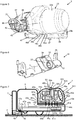
- the robot vacuum cleaner 1 comprises a docking station 2 which is designed to be connected to a power outlet supplied by the electrical network of the building (not shown).
- the docking station 2 includes a transformer 3 to reduce the voltage at the terminals of two electrical connectors 4a, 4b, for example a voltage of 21.9 volts or other low voltages.
- the robot vacuum cleaner 1 also comprises a mobile base 5 and a hand vacuum 6; when the hand-held vacuum cleaner 6 is engaged on the mobile base 5, said mobile base 5 can be attached to the docking station 2.
- the docking station 2 is positioned on a surface 7 which is flat, the mobile base 5 and the hand aspirator 6 engaged in one another can move on this surface 7 to suck the dust present on the surface 7 directly by means of said hand vacuum 6.
- the mobile base 5 comprises a navigation system 8 illustrated in part on the figures 2 , 8 and 9 .
- This navigation system 8 comprises two drive wheels 9a, 9b driven in rotation by two respective motors 10a, 10b and arranged on lateral sides 5a, 5b of the mobile base 5, a free wheel 11 arranged in the central part of a front side. 5c of the mobile base 5 and two balls 12a, 12b arranged on a rear side 5d of the mobile base 5 with a uniform distribution.
- the mobile base 5 can pivot to the left, to the right or on itself, advance or retreat, while remaining in a stable support on the surface 7.
- the navigation is managed by an electronic card 13 which receives data from two fall sensors 14a, 14b for detecting a void below, especially when the surface 7 is on a staircase.
- This electronic card 13 also receives data from proximity sensors (not shown), for example infrared sensors, arranged behind windows 14c over the entire front half-circumference of the mobile base 5, as illustrated by FIGS. Figures 1 and 2 these proximity sensors for detecting obstacles on the surface 7, including furniture or a wall (not shown).
- This electronic card 13 also receives data from physical sensors 14d, 14e, of the contact sensor type, implemented by the two left and right parts of the front half-circumference of the mobile base 5, these physical sensors 14d, 14e being activated by contact when the proximity sensors infrared did not detect the obstacle.
- the electronic card 13 receives data from a transmitter / receiver 15 which communicates with the docking station 2.
- the electronic card 13 acts accordingly on the two motors 10a, 10b to move randomly or even methodically, the mobile base 5 over the entire surface 7 to suck and to bring it back to the docking station 2 at the end of work, to allow the recharge of the robot vacuum cleaner 1.
- methodical displacement means the fact, including moving the movable base 5 following the walls via the proximity sensors and bouncing the movable base 5 over the obstacles according to predefined angles sequences, giving variable pulses to the motors 10a, 10b.
- the movable base 5 has a flattened cylindrical shape, like a puck, as illustrated in particular by the Figures 1 and 2 , which favors its random movements without risk of blockage vis-à-vis obstacles.
- the navigation system 8 could be implemented by any other variants known to those skilled in the art without departing from the scope of the invention. It is the same for the shape of the movable base 5, the flattened cylindrical shape being however preferred.
- the movable base 5 has a lower face 16 which is positioned parallel to the vicinity of the surface 7 to be sucked, because of the presence of the wheels 9a, 9b, 10 and the balls 12a, 12b.
- a lower face 16 On the figure 2 , we distinguish the presence of two electrical connectors 17a, 17b on this lower face 16; these electrical connectors 17a, 17b come into contact with the two electrical connectors 4a, 4b of the docking station 2 when the mobile base 5 is brought back to this docking station 2.
- the mobile base 5 comprises a suction part 18, illustrated in FIG. figure 6 , which comprises a suction opening 19 opening on the lower face 16, this suction mouth 19 being of elongate shape and extending transversely over the entire width of the lower face 16, as illustrated by FIG. figure 2 .
- a brush 20 is housed in this suction mouth 19, this brush 20 being driven in rotation by a motor 21 illustrated in figure 9 .
- This motor 21 is controlled by the electronic card 13.
- the electrical components of the mobile base 5, in particular the electronic card 13 and the motors 10a, 10b, 21 are electrically powered via the hand-held vacuum cleaner 6.
- the mobile base 5 has no set of batteries for its power supply, only the hand-held vacuum cleaner 6 being equipped with a set of batteries 22, illustrated in FIG. figure 8 which serves for the power supply not only of the hand-held vacuum cleaner 6, but also of the mobile base 5.
- the hand aspirator 6 comprises a body 23 having an elongate shape disposed in the transverse direction.
- This body 23 comprises a front portion 23a having more or less a cylindrical shape which integrates a suction turbine 24 and a cyclonic chamber 25 configured to filter and retain the waste aspired.
- This front portion 23a is extended forwards by a suction tube 26 which is provided at its end with a first nozzle 27.
- the body 23 also comprises a rear portion 23b which incorporates a first electronic card 28, a second card 29 and the battery pack 22, as illustrated in FIG. figure 8 .
- a handle 30 is attached to the rear of this rear portion 23b of the body 23, the suction tube 26 extending in opposition to the handle 30, in front of the front portion 23a, as shown in FIG. show the figures 4 and 5 .
- the movable base 5 comprises a housing 31 which has more or less a funnel shape, with an enlarged portion 31a and a narrowed portion 31b.
- the enlarged portion 31a has a semicylindrical bowl shape enabling the front part 23a of the body 23 of the hand-held vacuum cleaner 6 to be received in large proportion, as illustrated by FIG. figure 1 .
- the narrowed portion 31b allows the reception of the suction tube 26 and the first nozzle 27.
- the suction part 18, illustrated in FIG. figure 6 comprises a second endpiece 32 which extends upwardly and rearward the suction mouth 19, with which said second endpiece 32 communicates.
- the suction part 18 also comprises a plate 33 provided with a window 34 disposed above the second endpiece 32, said second ferrule 32 passing through said plate 33, as shown in FIG. figure 6 .
- This plate 33 closes and constitutes the bottom of the narrowed portion 31b of the housing 31, the second endpiece 32 being oriented towards the rear of the mobile base 5 in this narrowed portion 31b, as illustrated by FIG. figure 3 .
- a receiving zone 35 extends the housing 31 towards the rear of the mobile base 5, as illustrated by FIG. figure 3 .
- This receiving zone 35 receives the rear portion 23b of the body 23 of the hand-held vacuum cleaner 6 when the front portion 23a of said body 23 and the suction tube 26 are engaged in the housing 31, as illustrated by FIG. figure 1 .
- the first end 27 at the end of the suction tube 26 is fitted on the second endpiece 32 in the bottom of the narrowed portion 31b and the window 34 receives pins 36 extending in front of the first endpiece 27, as illustrated by figure 5 .
- These pins 36 are used to attach additional accessories (not shown) that can be reported on said first nozzle 27 during an individual use of the hand vacuum 6, for example a brush or an extension tube.
- the handling handle 30 comprises at its lower end a bolt 37 mounted in sliding connection inside said handle 30 so as to be retracted inside thereof.
- the bolt 37 is spring-biased 38 so as to naturally return it to the extended position illustrated in FIG. figures 4 and 5 , according to which said bolt 37 is protruding with respect to the lower face 39 of the rear part 23b of the body 23.
- the receiving zone 35 comprises a base 40 which receives said lower face 39 when the hand-held vacuum cleaner 6 is in the engaged position in the mobile base 5.
- This base 40 comprises a crevice forming a striker 41 which receives the latch 37 in said engaged position.
- the engagement of the hand-held vacuum cleaner 6 on the mobile base 5 is effected simply by a translation movement from the rear to the front, by inserting the suction tube 26 into the narrowed portion 31b of the housing 31, then the front portion 23a of the body 23 in the enlarged portion 31a of the housing.
- the shape of the housing 31 facilitates the proper positioning and introduction of the hand aspirator 6 in the mobile base 5.
- the first tip 27 on the hand vacuum 6 is preferably a male end and the second tip 32 on the mobile base 5 is preferably a female endpiece.
- the interlocking of the first endpiece 27 on the second endpiece 32 in the aforementioned engaged position allows the suction mouth 19, opening on the lower face 16 of the mobile base 5, to be directly connected to the suction tube 26 of the hand vacuum 6, which provides excellent suction quality, without any loss.
- a seal 42 is arranged inside the first nozzle 27 on the suction tube 26, as illustrated by FIGS. figures 5 and 8 , this seal 42 being positioned around the second endpiece 32 in said engaged position.
- the mobile base 5 comprises five first electrical connectors 44a, 44b, 44c, 44d, 44e positioned in a bottom 45 of the receiving zone 35, under the housing 31 which is adjacent to said bottom 45, as illustrated by FIG. figure 3 .
- These first five electrical connectors 44a, 44b, 44c, 44d, 44e are preferably constituted by metal pellets.
- the hand-held vacuum cleaner 6 comprises five second electrical connectors 46a, 46b, 46c, 46d, 46e positioned on a front face 47 of the rear part 23b of the body 23, under the front portion 23a of said body 23 which is adjacent to said front face 47, as shown in FIG. figure 5 .
- These five second electrical connectors 46a, 46b, 46c, 46d, 46e are also preferably constituted by metal pellets. In the aforementioned engaged position, the five second electrical connectors 46a, 46b, 46c, 46d, 46e respectively come into contact with the first five electrical connectors 44a, 44b, 44c, 44d, 44e.
- two 44a, 44b of the first five electrical connectors 44a, 44b, 44c, 44d, 44e are connected to the two electrical connectors 17a, 17b under the mobile base 5 by means of two conductor wires 47a, 47b, which allows their connection to the connectors. 4a, 4b on the docking station 2 when the mobile base 5 is positioned on this docking station 2, as explained above.
- These first two electrical connectors 44a, 44b come into contact with two 46a, 46b of the five second electrical connectors 46a, 46b, 46c, 46d, 46e in said engaged position.
- These two second electrical connectors 46a, 46b are connected to the first electronic card 28 by means of two son 48a, 48b conductors.
- This first electronic card 28 is itself connected to the positive terminals 49a and negative 49b of the battery pack 22 by means of two conductor wires 50a, 50b.
- the first electronic card 28 is configured to ensure this recharging of the battery pack 22 when the hand-held vacuum cleaner 6 is engaged on the mobile base 5 and said mobile base 5 is engaged on the docking station 2.
- the other three 44c, 44d, 44e of the first five electrical connectors 44a, 44b, 44c, 44d, 44e are connected to the electronic card 13 in the mobile base 5 by means of three son son 51a, 51b, 51c.
- the other three 46c, 46d, 46e of the five second electrical connectors 46a, 46b, 46c, 46d, 46e are connected to the first electronic card 28 by means of three son son 52a, 52b, 52c.
- the first conductive wire 52a is also connected to the second electronic card 29 in the hand-held vacuum cleaner 6.
- the second lead wire 52b is connected to a voltage transformer 53 on the first electronic card 28 which allows a reduction of the voltage at the terminals of the two electrical connectors 46a, 46b supplied from the docking station 2, in order to deliver a reduced voltage at the terminals of the electrical connectors 46d, 46e which serve to electrically supply the electronic card 13 and the motors 10a, 10b, 21 in the mobile base 5, when they are in contact with the two electrical connectors 44d, 44e on said mobile base 5
- This voltage transformer 53 makes it possible, for example, to convert a voltage of 21.9 volts into a voltage of 14.4 volts.
- the third conductor wire 52c is also connected to the negative terminal 49b of the battery pack 22.
- the first electronic card 28 is furthermore connected to the second electronic card 29 by means of two conducting wires 54a, 54b.
- the hand-held vacuum cleaner includes a switch-type on / off button 55 which is connected to the first electronic card 28 by means of two conductor wires 56a, 56b.
- the second electronic card 29 is configured to manage the operation of the hand-held vacuum cleaner 6 when it is used in the individual mode, that is to say when the hand-held vacuum cleaner 6 is detached from the mobile base 5 to suck d other surfaces than the surface 7, for example a table top, a shelf or the steps of a staircase (not shown), and when it is used in a robot mode, that is to say when the vacuum cleaner hand 6 and the mobile base 5 are engaged in one another.
- This second electronic card 29 acts on the suction turbine 24.
- the robot vacuum cleaner 1 starts operating in the robot.
- the electronic card 13 of the mobile base 5 comes into contact with the first electronic card 28 and the second electronic card 29 of the hand-held vacuum cleaner 5.
- the first electronic card 28 supplies, via the battery pack 22, the card 13 and the motors 10a, 10b, 21 of the mobile base 5, and the second electronic card 29 and the suction turbine 24.
- the electronic card 13 acts on the motors 10a, 10b and 21.
- the second electronic card 29 in relation with said electronic card 13, also acts on the suction turbine 24 to operate in robot mode, to ensure a suction flow rate adapted to said robot mode.
- the mobile base 5 stops working instantly because it is no longer powered.
- the first electronic card 28 and the second electronic card 29 detects this disconnection and start operating in individual mode, the second electronic card 29 adapting the suction flow of the suction turbine 24 to said individual mode.
- the first electronic card 28 manages the recharge of the battery pack 22, whatever the position of the on / off button.
- the front part 23a of the body 23 of the hand-held vacuum cleaner 6 comprises a ventilation grille 57 which is positioned upwardly, on the front side of the hand-held vacuum cleaner 6.
- This ventilation grid 57 makes it possible to evacuate the air output of the suction turbine 24 by avoiding directing this air in the face of the user when using the hand vacuum 6 in individual mode.
- the mobile base 5 comprises a guide channel 58 arranged above the housing 31.
- figure 1 shows that the ventilation grille 57 is positioned in the guide channel 58 when the hand aspirator 6 is engaged in the mobile base 5.
- the guide channel 58 directs the extracted air upwards, which avoids to lift the dust present on the surface 7 during aspiration in robot mode.
- the locking implemented by means of the bolt 37 and the striker 41 ensures, besides the nested retention of the first ferrule 27 on the second ferrule 32, maintaining the contacts between the first five electrical connectors 44a, 44b, 44c, 44d, 44e and the five second electrical connectors 46a, 46b, 46c, 46d, 46e. It would be possible to envisage variants of locking means of the hand-held vacuum cleaner 6 in the engaged position on the mobile base 5.
- the handling handle 30 comprises in the upper part a button 59 which actuates a locking mechanism 60 arranged between the front portion 23a and the rear portion 23b of the body 23, so as to allow the extraction of the front portion 23a when the hand vacuum cleaner 6 is detached from the mobile base 5, in order to empty the dust contained in the cyclonic chamber 25.
- the mobile base 5 may also comprise a keyboard (not shown) in connection with the electronic card 13 is to adjust different modes of operation of the robot vacuum cleaner 1 in robot mode, for example to set different navigation speeds and / or different suction speeds of the suction turbine 24. These different modes of operation will be programmed on the electronic card 13.
- This keyboard can also be used to start and stop the hand vacuum 6 and the mobile base 5 when they are coupled together, in which case the on / off button 55 on the vacuum cleaner will only allow to start and stop the vacuum cleaner to hand 6 when used individually.
- the electronic card 13 on the mobile base 5 and the second electronic card 29 on the hand vacuum 6 will be programmed accordingly.
- the handle 30 could be pivotally mounted on the hand aspirator 6 between a vertical position as illustrated in FIG. figure 4 and a horizontal position not shown (perpendicular to the position illustrated in figure 4 ).
- the pivoting of the handling handle 30 would actuate the bolt 37 which would be in this case arranged on the rear portion 23b of the body 23, the actuation of the bolt 37 being done through a transmission mechanism (not shown ).
- the bolt 37 In a first position of the handling handle 30, for example in a horizontal position, the bolt 37 would be retracted in said rear portion 23b and in a second position of the handling handle 30, for example in a vertical position, the bolt 37 would be salient of said rear portion 23b to be engaged in the striker 41 on the base 40 of the mobile base 5 when the hand vacuum 6 is engaged thereon.
- the principle of pivoting of the handling handle 30 described above for the first example could be repeated, keeping the latch 37 on the handling handle 30 and the latch 41 on the base 40. case, the pivoting of the handle 30 in the horizontal position would extract the bolt 37 of the striker 41 and, conversely, its pivoting in the vertical position would bring the bolt 37 in the striker 41 for locking the vacuum cleaner 6 engaged on the mobile base 5.
Landscapes
- Engineering & Computer Science (AREA)
- Mechanical Engineering (AREA)
- Robotics (AREA)
- Electric Vacuum Cleaner (AREA)
Applications Claiming Priority (1)
| Application Number | Priority Date | Filing Date | Title |
|---|---|---|---|
| FR1760113A FR3072868B1 (fr) | 2017-10-26 | 2017-10-26 | Aspirateur robot integrant un aspirateur a main amovible |
Publications (2)
| Publication Number | Publication Date |
|---|---|
| EP3476266A1 true EP3476266A1 (de) | 2019-05-01 |
| EP3476266B1 EP3476266B1 (de) | 2020-07-08 |
Family
ID=60765887
Family Applications (1)
| Application Number | Title | Priority Date | Filing Date |
|---|---|---|---|
| EP18202725.0A Active EP3476266B1 (de) | 2017-10-26 | 2018-10-25 | Roboterstaubsauger, der einen entfernbaren handstaubsauger umfasst |
Country Status (5)
| Country | Link |
|---|---|
| EP (1) | EP3476266B1 (de) |
| KR (1) | KR102585677B1 (de) |
| CN (2) | CN209847061U (de) |
| ES (1) | ES2810820T3 (de) |
| FR (1) | FR3072868B1 (de) |
Cited By (1)
| Publication number | Priority date | Publication date | Assignee | Title |
|---|---|---|---|---|
| GB2600731A (en) * | 2020-11-06 | 2022-05-11 | Dyson Technology Ltd | Robotic vacuum cleaning system |
Families Citing this family (1)
| Publication number | Priority date | Publication date | Assignee | Title |
|---|---|---|---|---|
| FR3072868B1 (fr) * | 2017-10-26 | 2019-10-18 | Seb S.A. | Aspirateur robot integrant un aspirateur a main amovible |
Citations (3)
| Publication number | Priority date | Publication date | Assignee | Title |
|---|---|---|---|---|
| KR20080028219A (ko) * | 2006-09-26 | 2008-03-31 | 엘지전자 주식회사 | 분리형 로봇 청소기 |
| US20120189507A1 (en) * | 2011-01-24 | 2012-07-26 | Ko Joseph Y | Modular automatic traveling apparatus |
| EP2656763A1 (de) * | 2012-04-23 | 2013-10-30 | Robert Bosch Gmbh | System mit einem Bodenstaubsauger und einem Handstaubsauger |
Family Cites Families (5)
| Publication number | Priority date | Publication date | Assignee | Title |
|---|---|---|---|---|
| IT1264951B1 (it) * | 1993-07-20 | 1996-10-17 | Anna Maria Boesi | Apparecchiatura aspirante per la pulizia di superfici |
| KR101208980B1 (ko) * | 2006-09-26 | 2012-12-06 | 엘지전자 주식회사 | 분리형 로봇 청소기 |
| CN103371770B (zh) * | 2012-04-12 | 2017-06-23 | 中弘智能高科技(深圳)有限公司 | 自走及手提两用式吸尘器 |
| WO2016008049A1 (en) * | 2014-07-18 | 2016-01-21 | Omachron Intellectual Property Inc. | Portable surface cleaning apparatus |
| FR3072868B1 (fr) * | 2017-10-26 | 2019-10-18 | Seb S.A. | Aspirateur robot integrant un aspirateur a main amovible |
-
2017
- 2017-10-26 FR FR1760113A patent/FR3072868B1/fr not_active Expired - Fee Related
-
2018
- 2018-10-25 EP EP18202725.0A patent/EP3476266B1/de active Active
- 2018-10-25 KR KR1020180128046A patent/KR102585677B1/ko active IP Right Grant
- 2018-10-25 ES ES18202725T patent/ES2810820T3/es active Active
- 2018-10-26 CN CN201821745215.6U patent/CN209847061U/zh not_active Withdrawn - After Issue
- 2018-10-26 CN CN201811256493.XA patent/CN109700377B/zh active Active
Patent Citations (3)
| Publication number | Priority date | Publication date | Assignee | Title |
|---|---|---|---|---|
| KR20080028219A (ko) * | 2006-09-26 | 2008-03-31 | 엘지전자 주식회사 | 분리형 로봇 청소기 |
| US20120189507A1 (en) * | 2011-01-24 | 2012-07-26 | Ko Joseph Y | Modular automatic traveling apparatus |
| EP2656763A1 (de) * | 2012-04-23 | 2013-10-30 | Robert Bosch Gmbh | System mit einem Bodenstaubsauger und einem Handstaubsauger |
Cited By (2)
| Publication number | Priority date | Publication date | Assignee | Title |
|---|---|---|---|---|
| GB2600731A (en) * | 2020-11-06 | 2022-05-11 | Dyson Technology Ltd | Robotic vacuum cleaning system |
| GB2600731B (en) * | 2020-11-06 | 2023-04-19 | Dyson Technology Ltd | Robotic vacuum cleaning system |
Also Published As
| Publication number | Publication date |
|---|---|
| KR20190046687A (ko) | 2019-05-07 |
| CN109700377A (zh) | 2019-05-03 |
| CN209847061U (zh) | 2019-12-27 |
| FR3072868A1 (fr) | 2019-05-03 |
| EP3476266B1 (de) | 2020-07-08 |
| ES2810820T3 (es) | 2021-03-09 |
| FR3072868B1 (fr) | 2019-10-18 |
| KR102585677B1 (ko) | 2023-10-06 |
| CN109700377B (zh) | 2021-11-12 |
Similar Documents
| Publication | Publication Date | Title |
|---|---|---|
| EP3476265B1 (de) | Roboterstaubsauger, der einen entfernbaren handstaubsauger umfasst | |
| EP3488749B1 (de) | Handstaubsauger ohne saugbeutel, der mit einem entfernbaren behälter ausgestattet ist | |
| EP3476266B1 (de) | Roboterstaubsauger, der einen entfernbaren handstaubsauger umfasst | |
| EP1340446B1 (de) | Verfahren zur automatischen Abreinigung von Filtern zentraler Staubsauganlagen und entsprechende Vorrichtung | |
| FR2872693A1 (fr) | Brosse d'aspiration destinee a un aspirateur et aspirateur correspondant | |
| WO2016097645A1 (fr) | Appareil de nettoyage a flux d'air | |
| EP3624660B1 (de) | Autonomer staubsauger mit drehbarem stab | |
| EP2201876B1 (de) | Staubsaugerdüse | |
| EP3488750B1 (de) | Handstaubsauger ohne saugbeutel, der mit einem entfernbaren behälter ausgestattet ist | |
| FR3080879A1 (fr) | Balai aspirateur pour le nettoyage de piscines | |
| EP3954261B1 (de) | Tragbarer staubsauger, der mit einem abnehmbaren filter ausgestattet ist | |
| EP4115785B1 (de) | Autonomer reinigungsroboter, der mit einer nassreinigungsvorrichtung ausgestattet ist | |
| EP3708057B1 (de) | Staubsauger, der eine teil eines mobilen verbindungselements umfasst | |
| EP4039147B1 (de) | Schlittenartige saugeinheit, die mit einer klappe für den zugang zu einer wiederaufladbaren batterie ausgestattet ist | |
| FR3086856A1 (fr) | Balai de nettoyage de sol a fonction electrique | |
| EP4186402A2 (de) | Staubsauger mit einem zwischen eingezogenen und ausgezogenen positionen bewegbaren saugkopf | |
| EP4186401A2 (de) | Staubsauger mit sekundärem saugkopf | |
| EP4039157A1 (de) | Schlittenartige ansaugeinheit, die mit einer klappe für den zugang zu einer wiederaufladbaren batterie ausgestattet ist | |
| EP4098169A1 (de) | Schlittenstaubsauger mit handgriff, der mit einer fernbedienung ausgestattet ist | |
| WO2023180653A1 (fr) | Aspirateur portatif équipé d'une poignée de préhension logeant une batterie rechargeable | |
| EP4088639A1 (de) | Autonomer reinigungsroboter, der mit einer nassreinigungsvorrichtung ausgestattet ist | |
| FR3068594A1 (fr) | Tete d'aspirateur deformable |
Legal Events
| Date | Code | Title | Description |
|---|---|---|---|
| PUAI | Public reference made under article 153(3) epc to a published international application that has entered the european phase |
Free format text: ORIGINAL CODE: 0009012 |
|
| STAA | Information on the status of an ep patent application or granted ep patent |
Free format text: STATUS: THE APPLICATION HAS BEEN PUBLISHED |
|
| AK | Designated contracting states |
Kind code of ref document: A1 Designated state(s): AL AT BE BG CH CY CZ DE DK EE ES FI FR GB GR HR HU IE IS IT LI LT LU LV MC MK MT NL NO PL PT RO RS SE SI SK SM TR |
|
| AX | Request for extension of the european patent |
Extension state: BA ME |
|
| STAA | Information on the status of an ep patent application or granted ep patent |
Free format text: STATUS: REQUEST FOR EXAMINATION WAS MADE |
|
| 17P | Request for examination filed |
Effective date: 20191025 |
|
| RBV | Designated contracting states (corrected) |
Designated state(s): AL AT BE BG CH CY CZ DE DK EE ES FI FR GB GR HR HU IE IS IT LI LT LU LV MC MK MT NL NO PL PT RO RS SE SI SK SM TR |
|
| GRAP | Despatch of communication of intention to grant a patent |
Free format text: ORIGINAL CODE: EPIDOSNIGR1 |
|
| STAA | Information on the status of an ep patent application or granted ep patent |
Free format text: STATUS: GRANT OF PATENT IS INTENDED |
|
| INTG | Intention to grant announced |
Effective date: 20200206 |
|
| GRAS | Grant fee paid |
Free format text: ORIGINAL CODE: EPIDOSNIGR3 |
|
| GRAA | (expected) grant |
Free format text: ORIGINAL CODE: 0009210 |
|
| STAA | Information on the status of an ep patent application or granted ep patent |
Free format text: STATUS: THE PATENT HAS BEEN GRANTED |
|
| AK | Designated contracting states |
Kind code of ref document: B1 Designated state(s): AL AT BE BG CH CY CZ DE DK EE ES FI FR GB GR HR HU IE IS IT LI LT LU LV MC MK MT NL NO PL PT RO RS SE SI SK SM TR |
|
| REG | Reference to a national code |
Ref country code: CH Ref legal event code: EP Ref country code: AT Ref legal event code: REF Ref document number: 1287539 Country of ref document: AT Kind code of ref document: T Effective date: 20200715 |
|
| REG | Reference to a national code |
Ref country code: DE Ref legal event code: R096 Ref document number: 602018005879 Country of ref document: DE |
|
| REG | Reference to a national code |
Ref country code: IE Ref legal event code: FG4D Free format text: LANGUAGE OF EP DOCUMENT: FRENCH |
|
| REG | Reference to a national code |
Ref country code: LT Ref legal event code: MG4D |
|
| REG | Reference to a national code |
Ref country code: AT Ref legal event code: MK05 Ref document number: 1287539 Country of ref document: AT Kind code of ref document: T Effective date: 20200708 |
|
| REG | Reference to a national code |
Ref country code: NL Ref legal event code: MP Effective date: 20200708 |
|
| PG25 | Lapsed in a contracting state [announced via postgrant information from national office to epo] |
Ref country code: FI Free format text: LAPSE BECAUSE OF FAILURE TO SUBMIT A TRANSLATION OF THE DESCRIPTION OR TO PAY THE FEE WITHIN THE PRESCRIBED TIME-LIMIT Effective date: 20200708 Ref country code: AT Free format text: LAPSE BECAUSE OF FAILURE TO SUBMIT A TRANSLATION OF THE DESCRIPTION OR TO PAY THE FEE WITHIN THE PRESCRIBED TIME-LIMIT Effective date: 20200708 Ref country code: NO Free format text: LAPSE BECAUSE OF FAILURE TO SUBMIT A TRANSLATION OF THE DESCRIPTION OR TO PAY THE FEE WITHIN THE PRESCRIBED TIME-LIMIT Effective date: 20201008 Ref country code: GR Free format text: LAPSE BECAUSE OF FAILURE TO SUBMIT A TRANSLATION OF THE DESCRIPTION OR TO PAY THE FEE WITHIN THE PRESCRIBED TIME-LIMIT Effective date: 20201009 Ref country code: SE Free format text: LAPSE BECAUSE OF FAILURE TO SUBMIT A TRANSLATION OF THE DESCRIPTION OR TO PAY THE FEE WITHIN THE PRESCRIBED TIME-LIMIT Effective date: 20200708 Ref country code: BG Free format text: LAPSE BECAUSE OF FAILURE TO SUBMIT A TRANSLATION OF THE DESCRIPTION OR TO PAY THE FEE WITHIN THE PRESCRIBED TIME-LIMIT Effective date: 20201008 Ref country code: PT Free format text: LAPSE BECAUSE OF FAILURE TO SUBMIT A TRANSLATION OF THE DESCRIPTION OR TO PAY THE FEE WITHIN THE PRESCRIBED TIME-LIMIT Effective date: 20201109 Ref country code: LT Free format text: LAPSE BECAUSE OF FAILURE TO SUBMIT A TRANSLATION OF THE DESCRIPTION OR TO PAY THE FEE WITHIN THE PRESCRIBED TIME-LIMIT Effective date: 20200708 Ref country code: HR Free format text: LAPSE BECAUSE OF FAILURE TO SUBMIT A TRANSLATION OF THE DESCRIPTION OR TO PAY THE FEE WITHIN THE PRESCRIBED TIME-LIMIT Effective date: 20200708 |
|
| PG25 | Lapsed in a contracting state [announced via postgrant information from national office to epo] |
Ref country code: PL Free format text: LAPSE BECAUSE OF FAILURE TO SUBMIT A TRANSLATION OF THE DESCRIPTION OR TO PAY THE FEE WITHIN THE PRESCRIBED TIME-LIMIT Effective date: 20200708 Ref country code: RS Free format text: LAPSE BECAUSE OF FAILURE TO SUBMIT A TRANSLATION OF THE DESCRIPTION OR TO PAY THE FEE WITHIN THE PRESCRIBED TIME-LIMIT Effective date: 20200708 Ref country code: LV Free format text: LAPSE BECAUSE OF FAILURE TO SUBMIT A TRANSLATION OF THE DESCRIPTION OR TO PAY THE FEE WITHIN THE PRESCRIBED TIME-LIMIT Effective date: 20200708 Ref country code: IS Free format text: LAPSE BECAUSE OF FAILURE TO SUBMIT A TRANSLATION OF THE DESCRIPTION OR TO PAY THE FEE WITHIN THE PRESCRIBED TIME-LIMIT Effective date: 20201108 |
|
| REG | Reference to a national code |
Ref country code: ES Ref legal event code: FG2A Ref document number: 2810820 Country of ref document: ES Kind code of ref document: T3 Effective date: 20210309 |
|
| PG25 | Lapsed in a contracting state [announced via postgrant information from national office to epo] |
Ref country code: NL Free format text: LAPSE BECAUSE OF FAILURE TO SUBMIT A TRANSLATION OF THE DESCRIPTION OR TO PAY THE FEE WITHIN THE PRESCRIBED TIME-LIMIT Effective date: 20200708 |
|
| REG | Reference to a national code |
Ref country code: DE Ref legal event code: R097 Ref document number: 602018005879 Country of ref document: DE |
|
| PG25 | Lapsed in a contracting state [announced via postgrant information from national office to epo] |
Ref country code: EE Free format text: LAPSE BECAUSE OF FAILURE TO SUBMIT A TRANSLATION OF THE DESCRIPTION OR TO PAY THE FEE WITHIN THE PRESCRIBED TIME-LIMIT Effective date: 20200708 Ref country code: RO Free format text: LAPSE BECAUSE OF FAILURE TO SUBMIT A TRANSLATION OF THE DESCRIPTION OR TO PAY THE FEE WITHIN THE PRESCRIBED TIME-LIMIT Effective date: 20200708 Ref country code: DK Free format text: LAPSE BECAUSE OF FAILURE TO SUBMIT A TRANSLATION OF THE DESCRIPTION OR TO PAY THE FEE WITHIN THE PRESCRIBED TIME-LIMIT Effective date: 20200708 Ref country code: CZ Free format text: LAPSE BECAUSE OF FAILURE TO SUBMIT A TRANSLATION OF THE DESCRIPTION OR TO PAY THE FEE WITHIN THE PRESCRIBED TIME-LIMIT Effective date: 20200708 Ref country code: SM Free format text: LAPSE BECAUSE OF FAILURE TO SUBMIT A TRANSLATION OF THE DESCRIPTION OR TO PAY THE FEE WITHIN THE PRESCRIBED TIME-LIMIT Effective date: 20200708 |
|
| PLBE | No opposition filed within time limit |
Free format text: ORIGINAL CODE: 0009261 |
|
| STAA | Information on the status of an ep patent application or granted ep patent |
Free format text: STATUS: NO OPPOSITION FILED WITHIN TIME LIMIT |
|
| PG25 | Lapsed in a contracting state [announced via postgrant information from national office to epo] |
Ref country code: AL Free format text: LAPSE BECAUSE OF FAILURE TO SUBMIT A TRANSLATION OF THE DESCRIPTION OR TO PAY THE FEE WITHIN THE PRESCRIBED TIME-LIMIT Effective date: 20200708 |
|
| 26N | No opposition filed |
Effective date: 20210409 |
|
| PG25 | Lapsed in a contracting state [announced via postgrant information from national office to epo] |
Ref country code: SK Free format text: LAPSE BECAUSE OF FAILURE TO SUBMIT A TRANSLATION OF THE DESCRIPTION OR TO PAY THE FEE WITHIN THE PRESCRIBED TIME-LIMIT Effective date: 20200708 Ref country code: MC Free format text: LAPSE BECAUSE OF FAILURE TO SUBMIT A TRANSLATION OF THE DESCRIPTION OR TO PAY THE FEE WITHIN THE PRESCRIBED TIME-LIMIT Effective date: 20200708 Ref country code: LU Free format text: LAPSE BECAUSE OF NON-PAYMENT OF DUE FEES Effective date: 20201025 |
|
| REG | Reference to a national code |
Ref country code: BE Ref legal event code: MM Effective date: 20201031 |
|
| PG25 | Lapsed in a contracting state [announced via postgrant information from national office to epo] |
Ref country code: SI Free format text: LAPSE BECAUSE OF FAILURE TO SUBMIT A TRANSLATION OF THE DESCRIPTION OR TO PAY THE FEE WITHIN THE PRESCRIBED TIME-LIMIT Effective date: 20200708 Ref country code: BE Free format text: LAPSE BECAUSE OF NON-PAYMENT OF DUE FEES Effective date: 20201031 |
|
| PG25 | Lapsed in a contracting state [announced via postgrant information from national office to epo] |
Ref country code: IE Free format text: LAPSE BECAUSE OF NON-PAYMENT OF DUE FEES Effective date: 20201025 |
|
| REG | Reference to a national code |
Ref country code: CH Ref legal event code: PL |
|
| PG25 | Lapsed in a contracting state [announced via postgrant information from national office to epo] |
Ref country code: TR Free format text: LAPSE BECAUSE OF FAILURE TO SUBMIT A TRANSLATION OF THE DESCRIPTION OR TO PAY THE FEE WITHIN THE PRESCRIBED TIME-LIMIT Effective date: 20200708 Ref country code: MT Free format text: LAPSE BECAUSE OF FAILURE TO SUBMIT A TRANSLATION OF THE DESCRIPTION OR TO PAY THE FEE WITHIN THE PRESCRIBED TIME-LIMIT Effective date: 20200708 Ref country code: CY Free format text: LAPSE BECAUSE OF FAILURE TO SUBMIT A TRANSLATION OF THE DESCRIPTION OR TO PAY THE FEE WITHIN THE PRESCRIBED TIME-LIMIT Effective date: 20200708 |
|
| PG25 | Lapsed in a contracting state [announced via postgrant information from national office to epo] |
Ref country code: MK Free format text: LAPSE BECAUSE OF FAILURE TO SUBMIT A TRANSLATION OF THE DESCRIPTION OR TO PAY THE FEE WITHIN THE PRESCRIBED TIME-LIMIT Effective date: 20200708 |
|
| PG25 | Lapsed in a contracting state [announced via postgrant information from national office to epo] |
Ref country code: LI Free format text: LAPSE BECAUSE OF NON-PAYMENT OF DUE FEES Effective date: 20211031 Ref country code: CH Free format text: LAPSE BECAUSE OF NON-PAYMENT OF DUE FEES Effective date: 20211031 |
|
| PGFP | Annual fee paid to national office [announced via postgrant information from national office to epo] |
Ref country code: IT Payment date: 20221013 Year of fee payment: 5 Ref country code: ES Payment date: 20221107 Year of fee payment: 5 Ref country code: GB Payment date: 20221027 Year of fee payment: 5 |
|
| PGFP | Annual fee paid to national office [announced via postgrant information from national office to epo] |
Ref country code: FR Payment date: 20231023 Year of fee payment: 6 Ref country code: DE Payment date: 20231011 Year of fee payment: 6 |