EP3475753B1 - Automated adjustment of light sheet geometry in a microscope - Google Patents
Automated adjustment of light sheet geometry in a microscope Download PDFInfo
- Publication number
- EP3475753B1 EP3475753B1 EP17816281.4A EP17816281A EP3475753B1 EP 3475753 B1 EP3475753 B1 EP 3475753B1 EP 17816281 A EP17816281 A EP 17816281A EP 3475753 B1 EP3475753 B1 EP 3475753B1
- Authority
- EP
- European Patent Office
- Prior art keywords
- light
- sheet
- sample
- imaging
- detection
- Prior art date
- Legal status (The legal status is an assumption and is not a legal conclusion. Google has not performed a legal analysis and makes no representation as to the accuracy of the status listed.)
- Active
Links
Images








Classifications
-
- G—PHYSICS
- G02—OPTICS
- G02B—OPTICAL ELEMENTS, SYSTEMS OR APPARATUS
- G02B21/00—Microscopes
- G02B21/0004—Microscopes specially adapted for specific applications
- G02B21/002—Scanning microscopes
- G02B21/0024—Confocal scanning microscopes (CSOMs) or confocal "macroscopes"; Accessories which are not restricted to use with CSOMs, e.g. sample holders
- G02B21/0032—Optical details of illumination, e.g. light-sources, pinholes, beam splitters, slits, fibers
-
- G—PHYSICS
- G02—OPTICS
- G02B—OPTICAL ELEMENTS, SYSTEMS OR APPARATUS
- G02B21/00—Microscopes
- G02B21/32—Micromanipulators structurally combined with microscopes
-
- G—PHYSICS
- G02—OPTICS
- G02B—OPTICAL ELEMENTS, SYSTEMS OR APPARATUS
- G02B21/00—Microscopes
- G02B21/0004—Microscopes specially adapted for specific applications
- G02B21/002—Scanning microscopes
- G02B21/0024—Confocal scanning microscopes (CSOMs) or confocal "macroscopes"; Accessories which are not restricted to use with CSOMs, e.g. sample holders
- G02B21/0052—Optical details of the image generation
- G02B21/0076—Optical details of the image generation arrangements using fluorescence or luminescence
-
- G—PHYSICS
- G02—OPTICS
- G02B—OPTICAL ELEMENTS, SYSTEMS OR APPARATUS
- G02B21/00—Microscopes
- G02B21/06—Means for illuminating specimens
-
- G—PHYSICS
- G02—OPTICS
- G02B—OPTICAL ELEMENTS, SYSTEMS OR APPARATUS
- G02B21/00—Microscopes
- G02B21/36—Microscopes arranged for photographic purposes or projection purposes or digital imaging or video purposes including associated control and data processing arrangements
- G02B21/365—Control or image processing arrangements for digital or video microscopes
- G02B21/367—Control or image processing arrangements for digital or video microscopes providing an output produced by processing a plurality of individual source images, e.g. image tiling, montage, composite images, depth sectioning, image comparison
-
- G—PHYSICS
- G02—OPTICS
- G02B—OPTICAL ELEMENTS, SYSTEMS OR APPARATUS
- G02B27/00—Optical systems or apparatus not provided for by any of the groups G02B1/00 - G02B26/00, G02B30/00
- G02B27/0025—Optical systems or apparatus not provided for by any of the groups G02B1/00 - G02B26/00, G02B30/00 for optical correction, e.g. distorsion, aberration
Definitions
- This description generally relates to light-sheet microscopy.
- Light-sheet microscopy is a technique for imaging the development and function of biological systems. In order to successfully produce high-resolution images, these microscopes achieve overlap between a thin sheet of light used to illuminate the sample and the focal plane of the objective used to form an image. Whenever this overlap is not present, spatial resolution and image contrast suffer.
- MICHAEL WEBER ET AL "Chapter 11 - Light Sheet Microscopy", Quantitative Imaging in Cell Biology, Methods in Cell Biology, vol. 123 describes general principles of light sheet microscopy, and describes methods that may be performed manually by the user to adjust the acquisition protocol and optimize the image quality.
- WO 2010/014244 describes a method and device for multi-directional selective plane illumination microscopy.
- a detector focal plane is alternatively illuminated with at least two counter-propagating, coplanar light sheets, and an image of a specimen cross-section positioned in the focal plane is detected while only one light sheet illuminates the specimen.
- the wavefront of the illumination beams may be deformed with adaptive optics using feedback from light transmitted through the specimen.
- RAPHAEL JORAND ET AL “Deep and Clear Optical Imaging of Thick Inhomogeneous Samples", PLOS ONE, vol. 7, no. 4 describes the use of wavefront sensor adaptive optics and selective plane illumination microscopy to correct distortions in three-dimensional biological imaging and to improve the quality of images from deep within thick inhomogeneous samples.
- EP 2 887 117 describes a device and method for selective plane illumination microscopy.
- WO 2014/150536 describes devices and methods for light sheet microscopy.
- a method includes: imaging a sample using light-sheet imaging.
- the light-sheet imaging includes generating light, forming one or more light sheets from the light at one or more positions within the sample along respective illumination axes, and recording images of fluorescence emitted along a detection axis from the sample due to the optical interaction between the one or more light sheets and the sample.
- the method includes measuring one or more properties relating to the light-sheet imaging; analyzing the one or more measured properties; and adjusting one or more operating parameters associated with light-sheet imaging based on the analysis of the one or more measured properties.
- the sample can include a live biological specimen that remains living throughout light-sheet imaging and during the measurement of the one or more properties.
- the one or more light sheets can be formed from the light at one or more positions within the sample by forming two light sheets from the light at one or more positions within the sample.
- a first light sheet extends along a first illumination axis and a second light sheet extends along a second illumination axis.
- the first illumination axis can be anti-parallel with the second illumination axis.
- the light sheets spatially and temporally overlap within the sample along an image plane, and optically interact with the sample within the image plane.
- the images of fluorescence can be recorded by recording, at each of a plurality of detection focal planes, images of the fluorescence emitted along the detection axis from the sample due to the optical interaction between the two light sheets and the sample.
- the temporal overlap between the light sheets can be within a time shift that is less than a resolution time that corresponds to a spatial resolution limit of the light-sheet imaging.
- the one or more measured properties can be analyzed by analyzing the one or more measured properties without making any assumptions about the sample.
- the one or more properties can be analyzed without making any assumptions about the sample by analyzing the one or more properties without making any assumptions about: the physical properties of the sample, the optical properties of the sample, and the distribution and number of fluorescent markers within the sample.
- the one or more properties relating to the light-sheet imaging can be measured by measuring one or more of: a quality of one or more recorded images, a position of the light sheet inside the sample, and an orientation of the light sheet inside the sample.
- the one or more operating parameters associated with light-sheet imaging can be adjusted by adjusting one or more of: an angle between the light sheet and a detection focal plane at which the images of fluorescence along a detection axis are recorded, the one or more positions at which the light sheet is formed within the sample, and a relative position between the light sheet and the detection focal plane.
- the one or more operating parameters associated with light-sheet imaging can be adjusted by adjusting characteristics of one or more of: the one or more light sheets, the sample, and a focal plane at which the images of fluorescence are recorded.
- the one or more properties relating to the light-sheet imaging can be measured by measuring the one or more properties at a time during which the images of fluorescence are not being recorded for performing the light-sheet imaging of the sample.
- the one or more operating parameters associated with light-sheet imaging can be adjusted by rotating one or more light sheets relative to the sample.
- the one or more operating parameters associated with light-sheet imaging can be adjusted by translating one or more light sheets along a direction perpendicular to the illumination axis.
- the one or more operating parameters associated with light-sheet imaging can be adjusted by translating one or more light sheets along a direction parallel to the illumination axis.
- the one or more operating parameters associated with light-sheet imaging can be adjusted by translating a waist of a light sheet along the illumination axis.
- the one or more operating parameters associated with light-sheet imaging can be adjusted by translating a focal plane at which the images of fluorescence are recorded along the detection axis.
- the one or more properties relating to the light-sheet imaging can be measured by: forming an image of a portion of the sample that is illuminated by the light sheet; and quantifying a quality of the formed image.
- the method can include creating a structured light sheet.
- the one or more properties relating to the light-sheet imaging can be measured by measuring one or more properties relating to imaging of the sample with the structured light sheet.
- the structured light sheet can be created by modulating a property of the formed light sheet at a frequency.
- the frequency of modulation can be determined based on an optical transfer function associated with performing light-sheet imaging.
- the property of the formed light sheet can be modulated at the frequency by modulating an intensity of the light sheet at the frequency as a function of spatial location within the image plane.
- the one or more properties relating to the light-sheet imaging can be measured by forming an image of a portion of the sample that is illuminated by the light sheet, the image including light radiating from a set of fluorescent markers within the sample; and measuring the property at each formed image in a plurality of formed images.
- Each formed image can correspond to a distinct portion of the sample that is illuminated by the light sheet.
- the image of the sample portion that is illuminated by the light sheet can be formed by forming the image of the sample portion at which images of fluorescence are recorded for performing light-sheet imaging.
- the one or more operating parameters associated with light-sheet imaging can be adjusted by adjusting a relative position between the light sheet and a focal plane defined by the location at which images are recorded.
- the light sheet can be formed by scanning the light along a scanning direction that is normal to the illumination axis to form the light sheet in a plane defined by the scanning direction and the illumination axis.
- the one or more properties relating to the light-sheet imaging can be measured by selecting at least one reference region of the sample; changing at least one operating parameter relating to the light-sheet imaging to a set of discrete values; and, for each value of the operating parameter in the set and at the selected reference region: recording an image of fluorescence emitted from the reference region; and determining a quality of each recorded image.
- the one or more measured properties can be analyzed by observing which operating parameter value in a range of operating parameter values at the selected reference region produces the recorded image with the highest quality; and storing a quantity associated with the observation for the operating parameter for this reference region.
- the quality of a recorded image can be determined by applying an image quality metric to the recorded image to produce a real number that represents the quality of the recorded image.
- the range of parameter values can be based on the set of discrete values of the at least one operating parameter.
- the method can include determining how to adjust the one or more operating parameters associated with light-sheet imaging based on the stored quantity, and this determination can be based on one or more constraints that limit how the one or more operating parameters can be adjusted.
- the at least one operating parameter relating to light-sheet imaging can be changed by changing one or more of a plane of the light sheet and/or a focal plane at which the images of fluorescence are recorded.
- At least one reference region of the sample can be selected by selecting a plurality of reference regions of the sample.
- the at least one operating parameter relating to light-sheet imaging can be changed by adjusting at least a first operating parameter relating to light-sheet imaging.
- the one or more operating parameters associated with light-sheet-imaging can be adjusted by adjusting at least a second operating parameter that is distinct from the first operating parameter.
- the method can include determining how to adjust the second operating parameter based on the stored quantities associated with the observation for the operating parameter for each reference region in the plurality of reference regions.
- the second operating parameter can be adjusted by adjusting an angle between the light sheet and the focal plane.
- the observation of which operating parameter value in the range of operating parameter values at the selected reference region produces the recorded image with the highest quality can be an observation of which focal plane at which fluorescence is detected produces the recorded image with the highest quality.
- the quantity associated with the observation that is stored can be a position in three dimensional space that is defined by the set of: a value at which the focal plane is positioned along a z direction and the corresponding reference region defined in the xy plane.
- the determination of how to adjust an angle between the light sheet and the focal plane can be a determination of a most likely plane passing through each the stored position in three dimensional space.
- the at least one reference region of the sample can be selected by: selecting a set of z reference positions in a z direction from a detection focal plane; and for each z reference position in the set, selecting a plurality of reference regions defined in the xy plane that is perpendicular to the z direction, wherein each of the reference regions is distinct from other reference regions.
- a microscope system includes at least one illumination subsystem, at least one detection subsystem, and a control system connected to the at least one illumination subsystem and the at least one detection subsystem.
- the illumination subsystem includes a light source and a set of illumination optical devices arranged to produce and direct a light sheet along an illumination axis toward a sample, and a set of actuators coupled to one or more illumination optical devices
- the detection subsystem includes a camera and a set of detection optical devices arranged to collect and record images of fluorescence emitted from the sample along a detection axis, and a set of actuators coupled to one or more of the camera and the detection optical devices.
- the control system is configured to: receive a measurement of one or more properties relating to light-sheet imaging with the at least one illumination subsystem and the at least one detection subsystem; analyze the one or more measured properties; and send a control signal to one or more actuators of the at least one illumination subsystem and the at least one detection subsystem based on the analysis.
- the sample can include a live biological specimen.
- the at least one illumination subsystem can include two illumination subsystems, each illumination subsystem arranged to direct the light sheet along a respective illumination axis, the illumination axes being anti-parallel with each other.
- the light sheets can spatially and temporally overlap within the sample along an image plane, and optically interact with the sample within the image plane; and the temporal overlap between the light sheets is within a time shift that is less than a resolution time that corresponds to a spatial resolution limit of the microscope system.
- the at least one detection subsystem can include two detection subsystems, each defining a detection axis, the detection axes being anti-parallel with each other.
- the actuators of the at least one illumination subsystem can include: an actuator configured to translate the light sheet about a transverse offset with respect to the illumination axis; an actuator configured to translate the light sheet about a longitudinal offset with respect to its position within the sample; an actuator configured to rotate the light sheet through an angle about the illumination axis; and an actuator configured to rotate the light sheet through an angle about a direction normal to the illumination axis.
- the illumination subsystem can include a scanning apparatus that is configured to scan light along a scanning plane to form the light sheet, the scanning plane being defined by the illumination axis and the normal direction about which the light sheet is rotated.
- the at least one detection subsystem can include: an objective lens configured to produce an image of the sample illuminated by the light sheet in an image plane; and a detector configured to detect, in the image plane, the image of the sample illuminated by the light sheet.
- the actuators of the at least one detection subsystem can include an actuator configured to translate the objective lens along the detection axis to thereby move the image plane.
- the sample can include a set of fluorescent markers; and the image of the sample illuminated by the light sheet is produced by the set of fluorescence markers radiating light of a fluoresced wavelength, the fluoresced wavelength being distinct from a wavelength of the light sheet.
- the one or more of the actuators can include one or more of a piezo electric actuator and a galvanometer scanner.
- the control system can be configured to analyze the recorded images of fluorescence and to create an image of the specimen based on the analysis.
- the measurement of one or more properties relating to light-sheet imaging can occur during a period that happens between recording images of fluorescence used for creating the image of the sample.
- the one or more received properties can be recorded images of fluorescence, and the control system can be configured to analyze the recorded images by generating an image quality metric based on the recorded images.
- a microscope includes: a source of light configured to produce light having a specified wavelength; illumination optics configured to form the light into a light-sheet at a position within a sample along an optical axis in the microscope; a first controller configured to translate the light sheet about a transverse offset with respect to the optical axis; a second controller configured to translate the light sheet about a longitudinal offset with respect to the position within the sample; a third controller configured to rotate the light sheet through a roll angle about the optical axis; and a fourth controller configured to rotate the light sheet through a yaw angle about a direction normal to the optical axis.
- the source of light can be a laser.
- the light produced by the laser can include a beam having a Gaussian profile through a cross-section of the beam, the beam having a waist at a location along the optical axis where the Gaussian profile of the beam has a minimum width.
- the second controller that is configured to translate the light sheet about the longitudinal offset with respect to the position within the sample can be configured to move the waist of the beam along the optical axis.
- the third controller that is configured to rotate the light sheet through the roll angle about the optical axis can include a dual-axis galvanometer scanner.
- the fourth controller that is configured to rotate the light sheet through a yaw angle about the direction normal to the optical axis can include a dual-axis pivot galvanometer scanner having a vertical tilting mirror and a lateral tilting mirror.
- the vertical tilting mirror is configured to angularly displace the light in a first direction ⁇ x relative to the optical axis.
- the lateral tilting mirror is configured to angularly displace the light in a second direction ⁇ z relative to the optical axis.
- the second direction is normal to the first direction
- the yaw angle is an aggregation of ⁇ x and ⁇ z.
- the fourth controller that is configured to rotate the light sheet through a yaw angle about the direction normal to the optical axis can include two relay lenses.
- the dual-axis pivot galvanometer scanner can be positioned at a focal-distance between two relay lenses such that the collimated beam from the laser is focused onto the vertical scanning mirror by the first relay lens, and the second relay lens restores collimation and directs the beam onto the dual-axis light-sheet galvanometer scanner.
- the microscope can also include: an objective lens configured to produce an image of the sample illuminated by the light sheet in an image plane; a detector configured to detect, in the image plane, the image of the sample illuminated by the light sheet; and a fifth controller configured to translate the detector along the optical axis.
- the sample can include a set of fluorescent markers.
- the image of the sample illuminated by the light sheet can be produced by the set of fluorescent markers radiating light of a fluoresced wavelength into the objective lens.
- the fluoresced wavelength can be different than the specified wavelength.
- the microscope can include an adaptive controlling mechanism configured to control each of the first controller, the second controller, the third controller, the fourth controller, and the fifth controller according to an optimization of an image quality metric of the image.
- the adaptive controlling mechanism can be configured to perform a convolution operation on the image with a Gaussian kernel function prior to a performance of the optimization of the image quality metric.
- the image quality metric can be invariant to affine transformations of intensities of pixels of the image.
- the image quality metric can depend only on spatial frequencies that can pass through an optical band pass.
- the image quality metric can include a spectral image quality metric.
- the spectral image quality metric can include a Normalized Discrete Cosine Transform (DCT) Shannon Entropy metric.
- DCT Normalized Discrete Cosine Transform
- OTF optical transfer function
- the fifth controller can include a piezo actuator, the piezo actuator being configured to move the objective lens.
- the source of light and the illumination optics can be further configured to form the light into a second light-sheet at a second position within a sample along the optical axis in the microscope.
- the microscope can include: a second objective lens configured to produce a second image of the sample illuminated by the second light sheet in a second image plane; a second detector configured to detect, in the second image plane, the second image of the sample illuminated by the second light sheet; a sixth controller configured to translate the second light sheet about a second transverse offset with respect to the optical axis; a seventh controller configured to translate the second light sheet about a second longitudinal offset with respect to the second position within the sample; a eighth controller configured to rotate the second light sheet through a second roll angle about the optical axis; a ninth controller configured to rotate the second light sheet through a second yaw angle about a second direction normal to the optical axis; and a tenth controller configured to translate the second detector along the optical axis.
- a method includes: generating, in a microscope, light having a specified wavelength; forming a light-sheet from the light at a position within a sample along an optical axis in the microscope; forming an image of a portion of the sample that was illuminated by the light-sheet; generating an image metric based on the formed image; and based on the image metric, adjusting the light sheet by (i) translating the light sheet in a direction transverse to the optical axis, (ii) translating the light sheet in a direction along to the optical axis, (iii) rotating the light sheet through a roll angle about the optical axis, and (iv) rotating the light sheet through a yaw angle about a direction normal to the optical axis.
- a computer program product includes a nontransitory storage medium, the computer program product including code that, upon execution of the computer program product on an electronic device, causes the electronic device to perform a method.
- the method includes: generating an image metric based on an image of a sample in a microscope at a position within the sample illuminated with a light-sheet along an optical axis; and based on the image metric, adjusting the light sheet by (i) translating the light sheet in a direction transverse to the optical axis, (ii) translating the light sheet in a direction along to the optical axis, (iii) rotating the light sheet through a roll angle about the optical axis, and (iv) rotating the light sheet through a yaw angle about a direction normal to the optical axis.
- the automated spatiotemporal adaptive system improves spatial resolution and signal strength two to five-fold, recovers cellular and sub-cellular structures in many regions that are not resolved by non-adaptive imaging, adapts to spatiotemporal dynamics of genetically encoded fluorescent markers and robustly optimizes imaging performance during large-scale morphogenetic changes in living organisms.
- the automated spatiotemporal adaptive system is suited to high-resolution imaging of living specimens because it maintains high light-efficiency and maintains high spatial resolution (including high axial resolution and high lateral resolution).
- a microscope system 100 is designed for imaging of a sample or specimen 11 in its entirety and includes an automated spatiotemporal adaptive system 160 that operates within an optical microscope 110.
- the optical microscope 110 is a multi-view light-sheet microscope that images the specimen 11 using light-sheet imaging.
- the automated spatiotemporal adaptive system 160 turns the optical microscope 110 into a smart light-sheet microscope that is capable of substantially improving spatial resolution of the light-sheet imaging of the specimen 11 by continuously and automatically adapting to the dynamic optical conditions encountered in specimens that change during the course of the light-sheet imaging.
- a live specimen 11 that is a multicellular organism typically has a complex three-dimensional (3D) shape.
- the surrounding support matrix (for example, agarose), and the medium (for example, water) in the microscope chamber that holds the specimen 11 usually differ substantially, light refraction can occur at the surface of the specimen 11 and can lead to mismatches in relative position and 3D orientation of the planes of the light sheets 12, 14 and the detection planes 26, 28. These mismatches change as the light sheet 12, 14 is moved to different regions of the specimen 11 over the course of volumetric imaging.
- the specimen 41 includes four distinct regions C1, C2, C3, and C4, each having a distinct refractive index, n C1 , n C2 , n C3 , and n C4 .
- the support matrix 405 has a different refractive index n B and the environment surrounding the support matrix 405 has a distinct diffractive index n A .
- the light sheet 12 or 14 will be altered differently depending on the region that it encounters as it travels toward and through the specimen 41 and this causes changes in the direction and length of the optical path traversed by the light sheet 12, 14.
- wavelength-dependent effects and chromatic aberrations introduce additional mismatches in the planes of the light sheets 12, 14 and the detection planes 26, 28, and these mismatches vary as a function of imaging depth and depend on the spectral illumination and detection windows of fluorescent markers. Thermal, mechanical and electronic drifts in microscope components during live imaging can further contribute to a degradation of spatial resolution.
- fluorescent marker distributions frequently undergo spatiotemporal changes during imaging experiments, particularly in experiments involving the use of genetically encoded markers targeted to specific (potentially non-stationary) cell populations or the tracking of specific gene products.
- developing organisms such as early zebrafish (D. rerio) embryos during epiboly
- optical conditions change continuously as a function of time and spatial location in the sample.
- Live imaging of genetically encoded fluorescent markers such as a pan-neural fluorescent marker tracking the developing nervous system in Drosophila, is further complicated by spatiotemporal dynamics in marker expression. Recovering optimal resolution in the imaging experiment thus requires spatiotemporal adaptation of the microscope to the dynamic optical conditions while tracking dynamic fluorescent signals.
- the microscope system 100 includes the automated spatiotemporal adaptive system 160 (referred to herein as an adaptive system) that ensures spatiotemporal adaptive imaging.
- the adaptive system 160 is capable of continuously analyzing and optimizing (or improving) aspects associated with light-sheet imaging of the specimen 41.
- the adaptive system 160 can improve the spatial and temporal relationship between the planes of the light sheets 12, 14 and the detection planes 26, 28 across the volume of the specimen 41.
- the adaptation performed by the adaptive system 160 is performed in real time, which means that it is performed in conjunction with the performance of primary imaging acquisition using the optical microscope 110.
- the adaptive system 160 systematically assesses and optimizes spatial resolution across specimens 41 (such as living organisms) by adapting to the optical properties of the specimen 41 and its environment and because of this, the adaptive system 160, when integrated within the optical microscope 110, provides an automated multi-view light-sheet microscope 110.
- the adaptive system 160 includes a measurement 152 of one or more properties relating to imaging with the light sheets 12, 14 of the optical microscope 110; an automated computation framework 185 that receives the one or more properties from the measurement 152, performs one or more analyses based on this received measurement 152, and outputs one or more control signals based on the analyses; and an actuation apparatus 150 connected to the optical microscope 110 for controlling or adjusting one or more operating parameters of the optical microscope 110 based on received control signals from the framework 185.
- the operating parameters that are controlled or adjusted can be considered as degrees of freedom (DOF) for the operation of the optical microscope 110.
- DOF degrees of freedom
- the measurement 152 can relate to a quality of an image.
- image quality can be sampled at a set of reference regions (which can be reference planes) within the specimen 11.
- reference planes PL 0 -PL 4 are used to sample the image quality of the specimen 41.
- the image quality can be estimated based on an image quality metric.
- An image quality metric is defined as a function that takes an image as its argument and returns a real number.
- the optical microscope 110 is probed by perturbing (or changing incrementally) known operating parameters at each of the reference planes in the set across the specimen 11 and then analyzing how these perturbations impact the quality of the images sampled at these reference planes.
- Some of the images that are sampled may have a set of perturbed operating parameters that produce more blur (or defocus) in a sampled image, and thus the quality of such images in those reference planes is reduced.
- While other of the images that are sampled may have a set of perturbed operating parameters that reduce the blur (or defocus) in a sampled image, and thus the quality of such images is improved. Because the adaptive system 160 knows the set of parameters that are fed into the system during this probing, it is possible to determine which operating parameters produce images of higher quality.
- these image quality values can be compared with the current image obtained during the primary light -sheet imaging and the adaptive system 160 can decide whether to adjust one or more of the operating parameters of the optical microscope 110 to improve the imaging by sending a signal to the actuation apparatus 150.
- the one or more operating parameters that are adjusted as a result of the analysis of the measurement 152 may be distinct from or the same as the one or more operating parameters that are changed to perturb the optical microscope 110 while probing to determine the measurement 152.
- Figs. 5A-5E The operating parameters are discussed next with reference to Figs. 5A-5E before discussing the components of the actuation apparatus 150.
- the light sheet 12, 14 is represented generally as ls (where ls can be 12 or 14) and the detection focal plane 26, 28 is represented generally as fp (where fp can be 26 or 28).
- the specimen 41 is mounted in the support matrix 405. The illustrations of Figs. 5A-5E are not drawn to scale and may be exaggerated to show details.
- the actuation apparatus 150 is integrated within the optical microscope 110 to adjust one or more operating parameters associated with light-sheet imaging.
- the actuation apparatus 150 actuates one or more components within the optical microscope 110 based on instructions from the computation framework 185.
- the actuation apparatus 150 includes actuators coupled to elements of the optical microscope 110 for rotating and/or translating light sheet planes and/or detection planes in one or more of the three X, Y, and Z axes.
- the parameters I(ls) associated with translation of the light sheets ls along a direction (for example, along the Z axis) that is perpendicular to the illumination axis (the Y axis) can be referred to, respectively, as I(12) and I(14).
- the parameters D(fp) associated with the location of the detection focal plane fp taken along the Z axis can be referred to, respectively, as D(26) and D(28).
- the parameters ⁇ (ls) associated with the rotation of the light sheet ls about the propagation direction of the light sheet can be referred to, respectively, as ⁇ (12) and ⁇ (14). If the propagation direction of the light sheet ls lies on the Y axis, then the parameter can be considered an angle ⁇ (ls) rotated about the Y axis.
- the parameters ⁇ (ls) associated with the rotation of the light sheet ls about the axis defined by points representing the location of the waist of the light sheet ls can be referred to, respectively, as ⁇ (12) and ⁇ (14).
- the points of the waist location lie along a direction that is parallel with the X axis and thus, the parameters ⁇ (ls) are associated with rotating the light sheet ls about a direction parallel with the X axis.
- the actuation apparatus 150 includes actuators coupled to elements of the optical microscope 110 for translating the light sheet ls along the illumination axis which is parallel with the Y axis.
- the parameters Y(ls) associated with the location of the waists W(ls) of the light sheets ls taken along the Y axis can be referred to, respectively, as Y(12) and Y(14).
- the actuation apparatus 150 includes actuators coupled to elements of the optical microscope 110 (such as, for example, the detection subsystem 116, 118 or the specimen 11 holder) for changing a volume at which the fluorescence 36, 38 is imaged to thereby compensate for a change in geometry of the sample 11.
- the volume at which the fluorescence 36, 38 is imaged can be changed in the Z axis by moving the specimen 11 across a larger range of values along the Z axis.
- the actuators coupled to the detection subsystem 116, 118 can be adjusted.
- the specimen 11 can be moved instead, and then the adaptive system 160 would need to update the range across which the specimen 11 is moved to capture the full sample volume.
- the light sheets 12, 14 and the focal planes 26, 28 are still adjusted but only for the purpose of correcting mismatches between light sheets 12, 14 and focal planes 26, 28.
- the computation framework 185 includes algorithms for tracking the specimen 11 in each of the X, Y, and Z axes so that its geometrical center (or fluorescence center of mass) remains stationary.
- the actuation apparatus 150 includes actuators coupled to elements of the detection subsystem 116, 118 for correcting a wavefront of the fluorescences 36, 38.
- the actuators can be deformable mirrors or the actuators can be coupled to tube lenses in the detection subsystem 116, 118.
- the adaptive system 160 includes a fully automated computation framework 185 within the control system 180 that rapidly analyzes the measurement 152 from the optical microscope 110, and continuously optimizes or improves the spatial resolution across the volume of the specimen 11 in real time based on this analysis.
- the measurement 152 is a measurement of one or more properties relating to imaging with the light sheets 12, 14 of the optical microscope 110. In some implementations, the measurement 152 is obtained from one or more of the detection subsystems 116, 118.
- the measurement 152 can be a measurement of a geometry (for example, a size, shape, and/or a location) associated with the specimen 11.
- the measurement 152 can be a measurement relating to the image of the specimen 11 that is formed by the microscope system 100.
- the measurement 152 can be a quality of the image of the specimen 11 that is formed by the microscope system 100.
- the measurement 152 can be taken of a wavefront of the fluorescence 36, 38.
- an exemplary process workflow 600 for spatiotemporal adaptive imaging using the adaptive system 160 is illustrated.
- the primary image acquisitions 605 in a time-lapse experiment on the specimen 11 are performed by the microscope system 100 in a repeated and discrete fashion.
- the start of consecutive image acquisitions 605 can be separated by a time period T605.
- one or more sub-actions 615 of the adaptive system 160 are performed.
- the measurement 152 for the adaptive system 160 is performed during this idle time 610 and after the primary image acquisition 605 is completed.
- the measurements 152 are taken for as short a period of time as possible and they are therefore distributed in time during the time-lapse experiment in order to minimize photo-bleaching, photo-toxicity, and impact on temporal resolution in the imaging of the specimen 11 that can be caused from the performance of the measurements 152.
- the one or more sub-actions 615 that are performed during the idle time 610 can also include computations performed by the computation framework 185 based on the measurement 152 received during that idle time 610. It is also possible that the one or more sub-actions 615 that are performed during an idle time 610 include the computation framework 185 sending a signal to the actuation apparatus 150, which then adjusts one or more operating parameters associated with light-sheet imaging during the next primary image acquisition 605.
- the computation framework 185 may be beneficial for the computation framework 185 to acquire several sets of measurements 152 over a plurality of idle times 610 before performing an analysis based on a plurality of measurements 152 from plural idle times 610 before sending the signal to the actuation apparatus 150.
- an update 620 to the optical microscope 110 (which includes the computation framework 185 sending a signal to the actuation apparatus 150, and the actuation apparatus 150 actuating one or more components within the optical microscope 110 based on the instructions from the computation framework 185) can be performed after a plurality of idle times 610.
- the computation framework 185 can control when and where the images of a specimen 701 for use in the adaptive system 160 are taken.
- the measurement 152 can be an acquired image (of the fluorescence 36 or 38) taken at eight discrete and separated reference planes PL 0 , PL 1 , ... PL 7 that are parallel with the XY plane and are distributed through the specimen 71 at eight distinct locations Z 0 , Z 1 , ... Z 7 along the Z axis.
- some of the reference planes are more associated with the detection subsystem 116 that is more proximal to such reference planes while others of the reference planes (for example, planes PL 4 , PL 5 , PL 6 , and PL 7 ) are more associated with the detection subsystem 118 that is more proximal to such reference planes.
- a subset of reference planes typically located near the center of the specimen 71 at respective locations Z S-1 and Z S can be associated with both of the detection subsystems 116, 118.
- the related degrees of freedom associated with these sync planes are subject to constraints that differ from those used in the rest of the volume of the specimen 71 and measurements 152 performed at these sync planes are used to ensure spatial continuity throughout the volume of the specimen 71.
- a description of the adaptive system 160 is next, beginning with the optical microscope 110 and the actuation apparatus 150.
- Each illumination subsystem 112, 114 of the optical microscope 110 includes a respective light source 822, 824 and each light source 822, 824 outputs a light beam.
- the light beams output from each light source 822, 824 are modified by respective sets 832, 834 of optical components. These optical components modify properties such as direction, size, angle, geometry, etc. of the light beam to produce the respective light sheet 12, 14.
- the light sheets 12, 14 produced within the illumination subsystems 112, 114 can be produced by scanning an output of the respective light sources 822, 824, as discussed in detail below.
- the respective light sheet 12, 14 After passing through the sets 832, 834 of optical components, the respective light sheet 12, 14 is directed through a respective illumination objective 842, 844 which focuses the light sheet 12, 14 to an illumination plane within the specimen 11.
- the illumination objective 842, 844 can be a relatively long working distance air objective in some implementations.
- Each detection subsystem 116, 118 includes a respective detection objective 826, 828 that collects respective fluorescence 36, 38 emitted from the specimen 11.
- the fluorescence 36, 38 collected by respective detection objectives 826, 828 is then directed through a respective set 836, 838 of one or more optical components before entering a respective camera 846, 848.
- the measurement 152 of the one or more properties of light sheet imaging can therefore be a measurement of properties of the images output from the camera 846, 848, and this measurement 152 is directed to the computation framework 185 for processing and analysis.
- Each set 836, 838 of optical components can include a component such as a filter for rejecting light of wavelengths outside a wavelength band centered around the wavelength of the light to be detected.
- Each set 836, 838 of optical components can include one or more lenses (such as tube lenses) that focus the collected fluorescence onto a sensor of the respective camera 846, 848.
- the actuation apparatus 150 includes actuators 51(12), 51(14) that are physically coupled to respective illumination objectives 842, 844 for adjusting a waist of the light sheet 12, 14 along the illumination axis (which is generally parallel with the Y axis), with the location of the waists being given by parameters Y(12) and Y(14), respectively, as discussed above.
- the actuator 51(12), 51(14) can effect an adjustment to the waist of the respective light sheet 12, 14 by translating the respective illumination objective 842, 844 along the illumination axis (the Y axis).
- the actuation apparatus 150 includes actuators 52(12), 52(14) that are physically coupled to respective optical components within the respective sets 832, 834 to translate the illumination plane (which is parallel with the XY plane) of the light sheet 12, 14 along the detection axis (which is the Z axis).
- the location of the illumination plane of the light sheet 12, 14 on the Z axis is given by the parameter I(12), I(14).
- the actuation apparatus 150 includes actuators 53(12), 53(14) that are physically coupled to respective optical components within the respective sets 832, 834 to rotate the respective light sheet 12, 14 about the illumination axis (which is the Y axis).
- the angle at which the light sheet 12, 14 is rotated about the Y axis is given by the respective parameter ⁇ (12), ⁇ (14), which can be referred to as roll.
- the actuation apparatus 150 includes actuators 55(26), 55(28) that are physically coupled to respective detection objectives 826, 828 for adjusting a location of the focal plane 26, 28 along the detection axis (which is the Z axis), with the location of the focal plane 26, 28 being given by respective parameters D(26) and D(28), as discussed above.
- the actuator 55(26), 55(28) can affect an adjustment to the focal plane 26, 28 of the fluorescence 36, 38 by translating the respective detection objective 826, 828 along the detection axis.
- the actuation apparatus 150 includes actuators 56(16), 56(18) coupled to elements of the detection subsystem 116, 118 for changing a volume at which the fluorescence 36, 38 is imaged to thereby compensate for a change in geometry of the sample 11.
- the actuators 56(16), 56(18) can be coupled to one or more of the camera 846, 848, the optical components of the sets 836, 838, and the cameras 846, 848 for adjusting the distinct Z locations of the reference planes [PL 0 , PL 1 , ... PL K ] that are analyzed by the computation framework 185.
- the actuation apparatus 150 includes actuators 57(16), 57(18) coupled to elements of the detection subsystem 116, 118 for correcting a wavefront of the fluorescences 36, 38.
- the actuators can be deformable mirrors or coupled to tube lenses in the set 836, 838 of optical components.
- the framework 185 of the adaptive system 160 is able to compensate for spatiotemporal changes in the optical properties of the specimen 11, for local and global distribution and maturation of fluorescent markers in the specimen 11, and for mechanical and thermal drift in various components of the optical microscope 110.
- the optical scanner arrangement 1020 is controlled and adjusted by the actuators 52(14) and 53(14).
- the optical scanner arrangement 1020 deflects the light beam 1000 along the X axis to form a light sheet 1025, which is directed toward an f-theta lens 1030, a tube lens 1035, and the illumination objective 844, the output of which forms the light sheet 14.
- the optical scanner arrangement 1020 includes a first tilting mirror 1020A and a second tilting mirror 1020B that are used in combination to perform several functions, which are briefly described next.
- the tilting mirrors 1020A, 1020B are adjusted to scan the light beam 1000 across the X axis to form the light sheet 1025.
- the tilting mirrors 1020A, 1020B are adjusted to offset or translate the plane of the light sheet 14 along a direction perpendicular to the illumination axis (which is parallel with the Y axis); for example, the plane of the light sheet 14 can be offset along the Z axis. As discussed above, the amount of offset of the plane of the light sheet 14 perpendicular to the illumination axis is given by the parameter I(14). Moreover, the tilting mirrors 1020A, 1020B are adjusted to control or adjust the roll angle, ⁇ (14) of the light sheet 14, which is the rotation of the light sheet 14 about the Y axis.
- each of these arrangements 1005, 1020 is set up with dual-axis scanners (which means that their respective actuators control or rotate the light beam about two different axes).
- the primary function of the optical scanner arrangement 1020 is to deflect the incident light beam 1000 to produce an angular range that defines the height of the light sheet 14 along the X axis in the specimen 11. And, the angle of the light beam 1000 that exits the optical scanner arrangement 1020 is converted into a displacement along the X axis or direction by the f-theta lens 1030 because the optical scanner arrangement 1020 is positioned to be located at the focal plane of the f-theta lens 1030, thus producing a macroscopic light sheet 14.
- the pair of the tube lens 1035 and the illumination objective 844 focuses the macroscopic light sheet 14 output from the f-theta lens 1030 into the microscopic light sheet 14 at the specimen 11.
- the illumination objective 844 can be a relatively long working distance air objective.
- the control of the yaw angle ⁇ (14) of the light sheet 14 is described next.
- the yaw angle ⁇ (14) is a rotation of the light sheet 14 at the specimen 11 about the X axis defined by the points representing the location of the waist of the scanned light beam 14.
- the yaw angle ⁇ (14) is adjusted by either physically displacing the actuator 52(14) or 53(14) laterally or by displacing the light beam 1000 that interacts with the optical scanner arrangement 1020 laterally.
- the second approach (to displace the light beam 1000 that interacts with the optical scanner arrangement 1020 laterally) is more practical because it is a simpler design and can be performed in an automated and digitally-controlled manner.
- the light beam 1000 can be positioned off the optical axis anywhere in the XZ plane at the plane of the relay lens 1015.
- the first tilting mirror 1005A and the second tilting mirror 1005B are not engaged and are in a non-pivot and on-axis position, which means that the light sheet 14 has not been pivoted and the value of the yaw angle ⁇ (14) is zero.
- the first tilting mirror 1005A and the second tilting mirror 1005B are engaged and are in a pivot position, which means that the light sheet 14 has been pivoted and the value of the yaw angle ⁇ (14) is non-zero.
- the pivot optical arrangement 1005 is positioned between two relay lenses 1010 and 1015 at a distance of one focal length to each lens. Because of this, the combined system (of the pivot optical arrangement 1005 and the lenses 1010, 1015) introduces a parallel displacement of the light beam 1000 relative to its optical axis and that parallel displacement is converted by downstream optical components of the illumination subsystem 114 into a pivot motion or adjustment, that is the yaw angle ⁇ (14) at the specimen 11 location.
- Figs. 10C and 10D show the introduction of the displacement of the light beam 1000 to produce the pivot motion ⁇ (14).
- the pivoted light beam 1025 (shown in Figs. 10C and 10D ) is displaced laterally (along the Z axis) relative to the on-axis light beam 1025 (shown in Figs. 10A and 10B ) after the optical scanner arrangement 1020.
- the mirror 1005A displaces the light beam 1000 along X by angle ⁇ x.
- the mirror 1005B displaces the light beam 1000 along Z by angle ⁇ z.
- the cumulative effect of rotating both tilting mirrors 1005A and 1005B as shown in Figs. 10C and 10D is an angular displacement of the light beam 1000 in the XZ plane by an angle ⁇ relative to the on-axis/non-pivoted light beam 1000 of Figs. 10A and 10B at the tilting mirror 1005A.
- the rotation of the tilting mirrors 1005A, 1005B can be constrained in a manner to ensure that the overall effect of the adjustment due to the pivot optical arrangement 1005 is to cause the light sheet 14 to be deflected by the yaw angle ⁇ (14) at the specimen 11 without causing a deflection of the light sheet 14 about another axis other than the X axis.
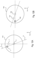
- the constraint that ensures this overall effect relates to the design of the optical scanner arrangement 1020, and is discussed next with reference to Figs. 11 , 12A, and 12B . As shown in Fig.
- This angle ⁇ defines the orientation of the shifted position of the light beam 1000 relative to the X axis at the relay lens 1015, as shown in Figs. 12A and 12B . If the actuator pair 52(14) and 53(14) is a dual-axis scanner such as the model 6215H by Cambridge Technology using a 61021506R40 XY mount, then the value of ⁇ is about 17° (but other values are possible).
- the pivot location P at the relay lens 1015 at which the light beam 1000 impinges should lie on a constraint line CL in the XZ plane.
- the constraint line CL is at an angle ⁇ relative to the X axis. This means that the displacement of the light beam 1000 by the pivot optical arrangement 1005 causes the pivot location P at the relay lens 1015 to remain on the constraint line CL in the XZ plane.
- the light beam 1025 remains deflected along the Z axis only and does not exhibit any deflection along the X axis. This is evident from the position of the deflected plane 1200 at the f-theta lens 1030.
- the light beam 1000 is adjusted by the pivot optical arrangement 1005 so that the shifted pivot location P' at the relay lens 1015 is deflected from the constraint line CL, as shown in Fig. 12A , then the light beam 1025 output from the optical scanner arrangement 1020 is now deflected along both the Z axis and the X axis, as shown in Fig. 12B . This is evident from the position of the deflected location 1210 at the f-theta lens 1030. Because of this, the light sheet 14 output from the tube lens 1035 and the illumination objective 844 is rotated about not only the X axis but also the Z axis.
- the orientation of the pivot location P flips by 90° - ⁇ as the light beam 1025 exits the optical scanner arrangement 1020 and impinges upon the f-theta lens 1030.
- the actuator 54(14) displaces the light beam 1000 by an angle of ⁇ x to create a lateral displacement after the optical scanner arrangement 1020.
- the light beam 1000 is displaced by ⁇ z.
- the position of the rotation axis of the light beam 14 (which relates to both the yaw angle ⁇ (14) and the roll angle ⁇ (14)) can be changed by translating the light sheet 1000 according to the value of the light sheet offset I(14).
- the optical microscope 110 includes the two illumination subsystems 112, 114, which include the light sources 822, 824, which can be laser systems, two detection subsystems 116, 118, a specimen chamber that houses the specimen 11, a positioning system for adjusting the position of the specimen 11 within the chamber in the X, Y, or Z axes, a computer workstation and real-time electronics for the control system 180 that provides for control of the microscope 110 and data acquisition, LabVIEW-based software for control of the microscope 110, and a Java and LabVIEW-based software for the computation framework 185.
- the control system 180 that provides for control of the microscope 110 and data acquisition
- LabVIEW-based software for control of the microscope 110
- Java and LabVIEW-based software for the computation framework 185.
- the light source 822, 824 is formed from a single laser source, the output of which is split to form the two beams for use in each illumination subsystem 112, 114.
- the single laser source can be a pulsed titanium: sapphire (Ti:Sapphire) laser, such as the Chameleon Ultra II by Coherent, Inc.) that outputs a light beam having a wavelength in the infrared (IR) range, for example, a wavelength of value between 650 nm and 1100 nm.
- the light from the single laser source can be split with beam-splitting optics from, for example, Melles Griot, Casix, or Linos.
- the beam splitter can be a model PBSH-450-2000-100 broadband polarizing cube beam splitter by Melles Griot or a WPA 1312-2-700-1000 achromatic 1 ⁇ 2 wave plate by Casix.
- the light from the light source 822, 824 can be directed through a Pockels cell such as a model 350-80-LA-02 KD*P series electro-optic modulator and a model 302RM driver by Canoptics.
- the light source 822, 824 consists of a plurality of lasers, such as a laser array with three solid-state lasers coupled into a dual-port fiber module, fiber collimators, and dichroic mirrors for combining the laser beams in the visible and IR portions of the spectrum.
- a solid-state laser coupled into a dual-port fiber module is a SOLE ® Laser Light Engine produced by Omicron-Laserage Laser area GmbH of Rodgau-Dudenhofen, Germany such as a SOLE-3 from Omicron.
- each detection subsystem 116, 118 it is possible to use a plurality of light sources and/or a plurality of light sheets having different colors at any given time, that is simultaneously, and equip each detection subsystem 116, 118 with dichroic beam splitters and a plurality of cameras, such that different color channels can be recorded simultaneously.
- each illumination subsystem 112, 114 includes a laser shutter such as a Uniblitz laser shutter model VS14S2ZM1-100 having an AlMgF2 coating with a VMM-D3 three-channel driver.
- Each illumination subsystem 112, 114 can include a filter wheel equipped with notch and neutral density filters.
- the filter wheel can be model 96A351 filter wheel controlled by model MAC6000 DC servo controller by Ludl
- the neutral density filter can be an NDQ neutral density filter by Melles Griot
- the notch filter can be a laser cleanup notch filter model 488/10, 561/10, or 594/10 by Chroma.
- the tilting mirrors 1005A, 1005B of the pivot optical arrangement 1005 can be silver-coated 6 mm mirrors and the actuator 54(14) of the pivot optical arrangement 1005 can be a two-axis galvanometer scanner onto which the silver-coated mirrors are fixed.
- the two-axis galvanometer scanner can be model 6215HSM40B galvanometer scanner by Cambridge Technology with a MicroMax 673XX dual-axis integrating servo driver amplifier.
- the silver-coated 6 mm mirrors can be mounted to the scanner as a set.
- the power supply for the actuator 54(14) can be a MK320S-24 power supply by Astrodyne.
- the tilting mirrors 1020A, 1020B of the optical scanner arrangement 1020 can be silver-coated 6 mm mirrors and the actuator 52(14)/53(14) of the optical scanner arrangement 1020 can be a two-axis galvanometer scanner onto which the silver-coated mirrors are fixed.
- the two-axis galvanometer scanner can be model 6215HSM40B galvanometer scanner by Cambridge Technology with a MicroMax 673XX dual-axis integrating servo driver amplifier.
- the silver-coated 6 mm mirrors can be mounted to the scanner as a set.
- the power supply for the actuator 54(14) can be a MK320S-24 power supply by Astrodyne.
- the relay lenses 1010, 1015 can be a relay lens pair, such as model 49-361-INK by Edmund Optics.
- the f-theta lens can be a custom f-theta lens supporting a light beam 1025 having a wavelength of about 488 nm to about 1100 nm, such as a model 66-S80-30T-488-1100nm by Special Optics.
- the tube lens 1035 and the illumination objective 844 can be a matched set such as made by Olympus or Nikon, which can be optimized for one- and two-photon excitation.
- the detection objectives 826, 828 can be high numerical aperture water-dipping detection objectives having the following exemplary specifications.
- the detection objective can provide a magnification of 16x or 20x and have a numerical aperture of at least 0.8.
- the detection objective can be model CFI60/75 LWD water-dipping series by Nikon or an apochromat/plan-apochromat water-dipping series by Carl Zeiss.
- the set of optical components 836, 838 can include a tube lens matched to respective detection objective 826, 828 plus a filter wheel equipped with an appropriate filter at the input to the camera 846, 848.
- the tube lens matched to the detection objective 826, 828 can be a CFI second lens unit by Nikon or an AxioImager 130 mm ISD tube lens by Carl Zeiss.
- the filter wheel can be a model 96A354 filter wheel with a MAC6000 DC servo controller by Ludl.
- the filter on the filter wheel can be one or more of a RazorEdge and EdgeBasic long-pass filter at 488 nm, 561 nm, and/or 594 nm or a BrightLine band-pass filter at 525 nm and/r 550 nm by Semrock.
- the actuator 55(26), 55(28) for the detection objective 826, 828 can be a piezo positioner such as a model P-622.1CN PIHera piezo linear stage and using E-665 piezo amplifier and servo controller made by Physik Instrumente.
- the camera 846, 848 can be an Orca Flash 4.0 v2 camera with a JULABO water chiller by Hamamatsu.
- the specimen 41 is mounted in a support matrix 405 that is supported by a holder 410. That holder is positioned within a specimen chamber that has four openings for permitting the light sheets 12, 14 to enter the specimen 41 and for permitting the fluorescence 36, 38 to enter the respective detection subsystems 116, 118.
- the specimen chamber also includes an opening for receiving the specimen 41.
- the chamber can be manufactured from black Delrin.
- the specimen holder 410 can be a holder cup manufactured from medical-grade stainless steel.
- the specimen holder 410 can be mounted to a multi-stage positioning system for moving the specimen holder 410 and therefore the specimen 41 along any one of the X, Y, or Z axes.
- the specimen holder 410 can be mounted to three translation stages, each translation stage arranged to translate the specimen holder 410 along one of the X, Y, or Z axes.
- the translation stage can be a model M-111K046 stage by Physik Instrumente.
- the specimen holder 410 can be mounted to a rotary stage such as a model M-116.2DG rotary stage by Physik Instrumente.
- the multi-stage positioning system can include a motion input/output interface and amplifier and a motion controller that communicates with the control system 180.
- the amplifier can be a model C-809.40 4-channel servo-amplifier by Physik Instrumente and the motion controller can be a model PXI-7354 4-axis stepper/servo motion controller by National Instruments.
- the control system 180 includes hardware such as one or more output devices (such as a monitor or a printer); one or more user input interfaces such as a keyboard, mouse, touch display, or microphone; one or more processing units; including specialized workstations for performing specific tasks; memory (such as, for example, random-access memory or read-only memory or virtual memory); and one or more storage devices such as hard disk drives, solid state drives, or optical disks.
- the processing units can be stand-alone processors, or can be sub-computers such as workstations in their own right.
- the control system 180 can be designed as a control system 1380 having a distributed architecture in which some functions are allocated or located on a host computer (such as a high-performance workstation) 1380A while other functions are allocated or located on a real-time control system 1380B.
- a host computer such as a high-performance workstation
- the user interface, short-term data storage, data management software, and the image acquisition and file logging can be located on the high-performance workstation.
- the instrument control (the control for the optical microscope 110), the waveform generation, and experiment sequencing control software can be located on the real-time control system.
- the high-performance workstation 1380A and the real-time control system 1380B can, for example, communicate by way of a TCP/IP server client architecture 1382.
- the control system 1380 also includes a library 1390 for storing algorithms relating to the adaptive process for use by the computation framework 185.
- This library 1390 includes algorithms for focus and image quality metrics; the programming interface for state modeling and optimization; algorithms for mapping the three-dimensional geometry of the light sheet 12, 14 inside the specimen 11; and an interface for integrating the adaptive process with the primary control software.
- the real-time control system 1380B is a PXI-8110 real-time controller (by National Instruments).
- This real-time controller can be equipped with four PXI-6733 high-speed analog input/output interface boards (by National Instruments), a PXI-8432/2 serial interface board (by National Instruments), and a PXI-7354 four-axis stepper/servo motion controller (by National Instruments), as well as a C-809.40 four-channel servo amplifier (by Physik Instrumente) and four BNC-2110 shielded connector blocks (by National Instruments).
- the software layer for real-time instrument control, waveform generation, experiment sequencing is deployed on the PXI-8110 real-time controller of the real-time control system 1380B.
- the PXI chassis holds four PXI-6733 8-channel analog output modules, which are used to control the galvanometer scanners (that is, the actuators 52(12, 14), 53(12,14), and 54(14)), the light sources 822, 824, the triggers for the cameras 846, 848, the piezo positioners (for actuators 51(12, 14) and 55(26, 28), the Pockels cell, and shutter states.
- Other PXI modules are used to control filter wheels and the motion of the holder 410.
- the high-performance computer workstation 1380A is a high-performance computer workstation by Colfax International).
- This workstation can be equipped with two Xeon E5-2687W CPUs (Intel), 192 GB of memory allocated to imaging ring buffers, 14 SAS hard disks (2.5 XE 900 GB, Western Digital) combined into two RAID-0 arrays using an RS2WG160 SAS RAID controller (Intel) for concurrent streaming from two sCMOS cameras and an X520-SR1 10G fiber controller (Intel) for data offloading to the storage server.
- the workstation 1380A includes software modules for receiving, processing and online visualization of image data streams and a graphical user interface (GUI) for configuring primary imaging experiments and adaptive control using the adaptive system 160.
- GUI graphical user interface
- the adaptive system 160 operates in two distinct modes: an initial system optimization prior to primary light-sheet image acquisitions in a time-lapse imaging experiment on the specimen 11, and microscope state updates during the time-lapse experiment (such as shown in Fig. 6 ).
- a user of the adaptive system 160 conducts the initial system optimization mode, which automatically determines the values to use for each parameter [for example, Y(12, 14), D(26, 28), I(12,14), ⁇ (12,14), and ⁇ (12,14)] for each reference plane PL in the specimen 11 and for each wavelength of the light sheet 12, 14, by executing multiple converging iterations of microscope state adaptation.
- the microscope state updates (which are assumed to be small corrections) occur at the user-defined intervals between experimental time points, as discussed above with reference to Fig. 6 .
- This ensures that continuous spatiotemporal adaptation of the optical microscope 110 to dynamic changes in morphology and optical properties of the specimen 11, fluorescent marker distributions inside the specimen 11, and optical properties of the environment of the specimen 11.
- the computation framework 185 monitors image quality exclusively during the idle time between time-point acquisitions (using less than 5% of the total microscope bandwidth) and quickly searches for better parameter settings at user-defined reference planes PL distributed throughout the volume of the specimen 11, 41 (typically 4-8 planes that partition the volume in 20-80 ⁇ m steps).
- reference planes PL distributed throughout the volume of the specimen 11, 41 (typically 4-8 planes that partition the volume in 20-80 ⁇ m steps).
- an algorithm is developed that is capable of computing optimal settings for three parameter classes simultaneously from a single defocus image sequence. This algorithm reconstructs the 3D light-sheet geometry inside the specimen 11 and thereby determines light-sheet angles ⁇ and ⁇ as well as light-sheet defocus offsets I.
- Dynamic constraints relate to image quality measurements, presence or absence of local signal and local light-sheet geometry in the sample.
- substitution constraints automatically tackle the lack of fluorescence signal at certain time points and at certain spatial locations in the specimen 11.
- a procedure 1400 is performed by the optical microscope 110 under control of the control system 180 for adaptive imaging.
- the procedure 1400 includes imaging a sample (such as specimen 11, 41) using the light-sheet imaging (1405) under control of the control system 180.
- the light-sheet imaging refers to the primary image acquisitions 605 in a time-lapse experiment on the specimen 11.
- light-sheet imaging (1405) includes generating light, forming one or more light sheets 12, 14 from the light at one or more positions within the sample along respective illumination axes, and recording images of fluorescence 36, 38 emitted along a detection axis from the sample due to the optical interaction between the one or more light sheets and the sample.
- the one or more properties relating to light-sheet imaging are measured according to a procedure 1510.
- the procedure 1510 is performed by the optical microscope 110 under control of the adaptive system 160, and specifically the computation framework 185.
- At least one reference region of the sample 11 is selected (1511) for probing by the adaptive system 160.
- the computation framework 185 can send a signal to the actuation apparatus 150 to configure the optical microscope 110 to probe the selected reference region of the sample 11 (for example, by adjusting properties of the detection subsystem 116, 118 and/or the illumination subsystem 112, 114).
- at least one operating parameter relating to the light-sheet imaging is changed to a discrete value of a set of discrete values (1512).
- the computation framework 185 can send a signal to the actuation apparatus 150 based on the discrete value of the operating parameter.
- the adaptive system 160 is ready to probe the quality of imaging at a particular reference region and discrete value of at least one operating parameter.
- the operating parameter relating to light-sheet imaging that is changed (1512) can be a plane of the light sheet and/or a focal plane 26, 28 at which the images of fluorescence 36, 38 are recorded.
- the image of fluorescence 36 or 38 emitted from the reference region is recorded by the detection subsystem 116, 118 (1513).
- This recorded image is sent to the computation framework 185, which determines a quality of the recorded image (1514).
- the quality of the recorded image can be determined (1514) by applying an image quality metric to the recorded image to produce a real number that represents the quality of the recorded image.
- the computation framework 185 determines whether the operating parameter should be changed to another discrete value in the set of discrete values (1515). If so, then the computation framework 185 proceeds to change the operating parameter to another discrete value in the set of discrete values (1512).
- the procedure 1510 performs a procedure 1530 for analyzing the qualities of the recorded images, as shown in Fig. 15B .
- the computation framework 185 determines whether other reference regions of the sample 11 need to be probed (1516), and if so, the next reference region of the sample is probed.
- the procedure 1530 that performs the analysis includes the computation framework 185 (and specifically the software module 588 and/or software module 589) observing which operating parameter value in a range of operating parameter values at the selected reference region produces the recorded image with the highest quality (1531).
- the range of operating parameter values is not limited to the set of discrete values of operating parameters.
- a fitting strategy can be used based on the discrete value set to extract the location of an operating parameter value with higher resolution than the discrete values of operating parameters in the set.
- a quantity associated with the observation for the operating parameter for this reference region is then stored (1532) by the computation framework 185.
- the procedures 1510 and 1530 are performed by the software modules 587 and 589, as discussed next.
- the computation framework 185 determines how to adjust the one or more operating parameters associated with light-sheet imaging based on the stored quantity obtained during the procedure 1530 and then proceeds to adjust the one or more operating parameters (1450). These operating parameters that are adjusted at 1450 can therefore correspond to the operating parameters that are changed during probing (1512).
- the computation framework 185 can make the determination of how to adjust the one or more operating parameters also based on one or more constraints that limit how the one or more operating parameters can be adjusted.
- a plurality of reference regions of the sample can be selected at 1511.
- each of the reference planes PL 0 , PL 1 , ... PL K can be selected at 1511.
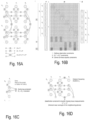
- a discussion relating to how the software modules 587 and 589 perform the procedures 1510 and 1530 is provided below with reference to Figs. 16A-16D and 17A-17E .
- the procedures 1510 and 1530 are performed by the software module 588.
- a plurality of reference regions of the sample are selected at 1511.
- Each reference region can correspond to a portion or sub-region of an image acquired by the detection subsystems 116, 118.
- a set of z reference positions in a z direction from a detection focal plane are selected, and for each z reference position in the set, a plurality of reference regions (that correspond to the sub-region of the image) defined in the xy plane that is perpendicular to the z direction are selected.
- Each of the reference regions is distinct from other reference regions.
- a z direction is a direction perpendicular to the Z axis
- the xy plane is a plane parallel with the XY plane defined by the X and Y axes.
- the operating parameter that is changed can be considered to be a first operating parameter relating to light-sheet imaging (such as a position of the plane of the light sheet 12, 14 or a position of the focal plane 26, 28).
- the one or more operating parameters associated with light-sheet-imaging that are adjusted (1450) correspond to a second operating parameter that is distinct from the first operating parameter.
- the second operating parameter than can be adjusted can be an angle between the light sheet 12, 14 and the focal plane 26, 28 of the detection subsystem 116, 118.
- the procedure 1510 can include a determination regarding how to adjust the second operating parameter and this determination can be based on the stored quantities associated with the observation for the operating parameter for each reference region in the plurality of reference regions (1532).
- the operating parameter value in the range of operating parameter values that is observed as producing the recorded image with the highest quality can be the focal plane that produces the recorded image with the highest quality.
- the quantity associated with the observation that is stored can be a position in three dimensional space that is defined by the set of: a value at which the focal plane is positioned along a z direction and the corresponding reference region defined in the xy plane.
- the computation framework 185 can determine a most likely plane passing through each the stored position in three dimensional space.
- a fundamental challenge in spatiotemporally adaptive imaging and optimizing the system state of complex, multi-axis microscopes such as the optical microscope 110 is the estimation and comparative analysis of image quality (1531).
- each operating parameter [I(12, 14), D(26,28), Y(12,14), ⁇ (12,14), ⁇ (12,14)] can be adjusted and evaluated in isolation to optimize or improve the image quality output from the microscope 110.
- all of these operating parameters are interdependent.
- the mathematical theory behind optimization is discussed. For the sake of simplicity and clarity only, this description relates to an optical microscope 110 having up to two illumination subsystems 112, 114 and up to two detection subsystems 116, 118, and considering only system parameters corresponding to the translation of the detection plane and the planes of the light sheets 12, 14. The theory is then extended to a global optimization theory.
- the ten exemplary state variables relevant to adaptive imaging that are shown are D(26), D(28), I(12), I(14), Y(12), Y(14), ⁇ (12), ⁇ (14), ⁇ (12), and ⁇ (14).
- the signs of the entries in M depend on the orientations of the axes. In practice, it is possible that different units are used for D(26), D(28), I(12), and I(14). If this is the case, a single unit is chosen and some entries in matrix M have values that differ from +1 or -1. Moreover, variables D(26), D(28), I(12), and I(14) have a priori undefined zero positions because they directly translate into actuator (for example, the actuator 55(26), 55(28), 52(12), 52(14), 53(12), or 53(14) commands. It follows that the distances computed by the matrix M also have undefined offsets - a physical zero distance does not necessarily correspond to a numerical zero. The formalism can handle these under-determinacies, as discussed below. In fact, the primary purpose of the following theory is to be able to reason about the focused state of the optical microscope 110 in the absence of prior system calibration.
- Focusing the system means finding the optimal focus vector F such that all detection and illumination planes coincide.
- Each component F u,v of vector F is related to an image J u,v acquired with detector D u , from which a focus value f ( J u,v ) can be computed.
- f J u,v
- ⁇ F is the correction vector to the current focus state that achieves the highest focus quality
- ⁇ S is the equivalent correction vector of the system state. Determining the system correction ⁇ S based on the focus state corrections ⁇ F requires the determination of the pseudo-inverse of the focus matrix M.
- exemplary pseudo-inverse is the Moore-Penrose pseudo-inverse.
- This formalism guarantees that the correction is mathematically well-defined.
- the process can be anchored by requiring one of the variables D(26), D(28), I(12), or I(14) to be fixed.
- the corrections ⁇ S can be found by first setting the corresponding components of the focus correction vector ⁇ F to zero and computing the state corrections ⁇ S .
- ⁇ S can be determined from ⁇ F and ⁇ F is found by searching for the F u , v ′ that maximize the corresponding ⁇ u , v ′ .
- the MINPACK based implementation in the Apache Commons Math library ( https: // commons.apache.org / proper / commons-math ) can be used with an initial step bound factor of 100, a cost relative tolerance of 10 -10 , a parameters relative tolerance of 10 -10 , and an orthogonality tolerance of 10 -10 .
- the probability distribution of the RMSD under the null hypothesis is computed empirically - which permits the computation of the corresponding p-value.
- the p-value ( p v ) is the probability of an event at least as extreme as the event that is considered (a given RMSD for true non-randomized data), assuming the truth of the null hypothesis.
- a threshold can be applied on an actual probability: 1 - p v which is usually well above 0.99 for good fits and can easily fall below 0.5 for highly noisy curves. In practice, thresholds such as 0.99 which have a well-defined interpretation are chosen while measurements that have a > 1% probability of being 'hallucinated' from noisy data are rejected.
- each detection subsystem 116, 118 can typically acquire high-quality image data only for about half of the specimen 11, that is, the half that the detection objective 826, 828 is facing, as shown in Figs. 7A and 7B .
- the detection subsystem 116 acquires high-quality image data for the half of the specimen 11 facing the detection objective 826.
- the respective other detection subsystem 116, 118 generally provides better image quality for the other half of the specimen 11, owing to the shorter detection path length.
- Fixing the variables D(26) and D(28) can be a better choice than fixing the variables I(12) or I(14), in particular when using highly accurate actuators 55(26), 55(28) such as piezo positioners for moving the respective detection objectives 826, 828 (in contrast to the less accurate galvanometer scanners or tip-tilt mirrors responsible for moving the light sheets 12, 14).
- a continuous and well-defined link between the two halves of the specimen 11 is established by carrying over light sheet positions I(12) and I(14) at plane Z S-1 to plane Zs and by solving the optical microscope system at plane Z S for D(28) by fixing both I(12) and I(14). This ensures seamless spatial continuity of the whole volume of the specimen 11.
- a temporal resolution of 30 seconds is preferred in order to ensure that cells do not move by more than half a cell diameter from one time point to the next.
- the solution to this problem is to distribute the measurements required for refocusing over multiple time points.
- the quanta of observation - the measurement that cannot practically be broken into smaller measurements - is the measurement of ⁇ u , v k for a given wavelength and depth Z.
- the acquisition duty cycle is often up to 90%. This means that less than 10% of time is available for the adaptive system 160 to perform image quality measurements. For typical acquisition settings in developmental time-lapse imaging, this translates to a time budget of 3 to 6 seconds between two time points available to acquire m images, compute the image quality metrics and determine the optimum parameter setting. Once all information is available to correct the microscope system state at depth Z, a new value S t+1,Z is computed, thus updating the previous value S t,Z .
- the fundamental difficulty in adding the angular degrees of freedom A(12) and A(14) as well as B(12) and B(14) is their coupling with I(12) and I(14) and indirectly with D(26) and D(28). Indeed, since the rotation axes of the light sheets 12, 14 are not necessarily matched to the geometrical center of a given optical section of the specimen 11, a change of the angular degrees of freedom A and/or B can also lead to a defocus of the light sheets 12, 14 relative to the detection focal planes 26, 28.
- Fig. 17A provides an overview of the nine perturbations, including the corresponding degrees of freedom affected by each perturbation and the amplitude of the perturbation.
- a volumetric DCTS focus value is shown as a function of time during an adaptive live imaging experiment of Drosophila embryogenesis (in which the specimen 11 is a Drosophila ), in which nine perturbations of the positions of the detection objective 826, 828 and offsets to the light sheets 12, 14 were introduced manually.
- Each of the nine perturbations introduces a temporary dip in focus quality (blue bars), which is subsequently restored through appropriate countermeasures initiated by the automated framework 185 for spatiotemporally adaptive imaging provided by the adaptive system 160.
- Perturbations #1 to #6 are instantaneous changes of individual degrees of freedom ( D 1 , D 2 , I 1 , I 2 ) and pairs of degrees of freedom ( D 1 and D 2 , I 1 and I 2 ).
- Perturbations #7 and #8 are two slow ramps (misaligning the system at a rate of 1 ⁇ m/min), involving first I 2 and then D 1 .
- the final perturbation #9 is a strong (8 ⁇ m) instantaneous change of I 2 and D 1 simultaneously that brings the system back to the initial baseline configuration prior to perturbation #1. This last perturbation is so strong that it is very unlikely to occur in a 'normal experiment' performed with the biological specimen 11 alone. However, this test was included as well in order to seriously challenge the system and evaluate its robustness under extreme conditions.
- a volumetric quality metric is computed based on the best performing focus metric (DCTS).
- DCTS best performing focus metric
- Fig. 17A shows that embryonic development leads to a positive longitudinal trend in the volumetric focus quality metric, which is due to the increase in nuclei density and the corresponding increase in fine details and high frequency textures in the imaging volume over time. More importantly, this visualization also shows how each perturbation leads to a temporary dip in the volumetric focus quality metric.
- Fig. 17B shows four degrees of freedom ( D 1 , D 2 , I 1 , I 2 ) of the microscope 110 as a function of time for reference plane z 2 .
- Fig. 17B shows the changes automatically applied by the system to the four degrees of freedom at reference plane z 3 .
- Reference plane z 3 was selected for this demonstration because images at this plane are linked to the unconstrained degree of freedom D 2 (which makes the data readout at this location particularly useful for evaluating system robustness).
- Fig. 17C shows a maximum-intensity projection (left) and a time series of an enlarged view of a small region of the embryo directly before and shortly after the fourth perturbation (right).
- the image sequence highlights the quadrant of the specimen 11 illuminated by objective O 4 and imaged with objective O 2 .
- Optimal focus quality is restored within 0.5 minutes (min) for the shown quadrant and within 2 min for the entire volume of the specimen 11.
- Fig. 17D shows the maximum-intensity projection (left) and the time series of an enlarged view of the small region of the embryo directly before and shortly after the fifth perturbation.
- the image sequence highlights the quadrant of the specimen 11 illuminated by objective O 4 and imaged with objective O 2 . Optimal focus quality is restored within 1 min for the shown quadrant and within 4 min for the entire volume of the specimen 11.
- Fig. 17E shows the maximum-intensity projection (left) and the time series of an enlarged view of the small region of the embryo directly before and shortly after the ninth perturbation.
- the ninth perturbation is the most severe system perturbation included in this benchmark.
- the two image sequences highlight regions in the quadrant of the specimen 11 illuminated by objective O 4 (right) and O 3 (left) and imaged with objective O 1 .
- Figs. 17C-17E show image sequences for quadrants illuminated by objective O 4 (right) and O 3 (left) and imaged from objective O 1 .
- Recovery from the fairly dramatic loss of focus quality seen in the image data for the quadrant illuminated by O 4 and imaged by O 1 takes 16 time points locally and 22 time points for the entire volume.
- Figs. 17C, 17D, and 17E show how image quality at plane z 3 is affected by three example perturbations #4, #5 and #9.
- perturbation #4 leads to a very small dip in the volumetric image quality metric, which is further confirmed by the almost imperceptible degradation of image quality following the perturbation shown in Fig. 17C .
- Perturbation #5 involves both detection objectives 826, 828 and is fully compensated at plane z 3 within 2 time points (1 minute) and throughout the entire volume within 10 time points (a period close to the length of the full-system correction cycle (see Fig. 17A ).
- the exceptionally strong perturbation #9 (amplitude: 8 ⁇ m) requires two full correction cycles to be fully corrected throughout the specimen volume.
- the adaptive system 160 is capable of successfully recovering even under extreme conditions, such as when confronted with strong external perturbations of its properly focused state. Notably, during this same test experiment the adaptive system 160 also successfully handled sample-induced perturbations by following and adjusting to the development of the live embryo.
- Fig. 18C shows how the measuring and correcting of angular mismatches ⁇ and ⁇ between the light sheet planes and the detection focal planes improves spatial resolution beyond the level achieved by spatiotemporally adaptive imaging restricted to only the degrees of freedom D, I, and Y.
- Representative examples of superficial and deep image regions in a Drosophila embryo are shown as enlarged views (purple, green) acquired with (top) and without (bottom) adaptive optimization of ⁇ and ⁇ .
- the line profiles (bottom) reveal sub-cellular features that are not resolved by correcting only D, I, and Y.
- Fig. 18D shows experimentally measured and theoretically predicted (black and gray lines in ⁇ plot) correction angles ⁇ across the volume of D. melanogaster embryo. Predictions were obtained with a ray optics model that assumes average refractive indices of 1.339 and 1.35 of the matrix in which the specimen 11 is held and the surface regions in the embryo. The good agreement between experiment and model suggests that two main optical effects are responsible for angular mismatches of light sheets and detection focal planes 26, 28 inside the specimen 11: 1. light sheet refraction at the interface between the embryo and surrounding matrix/medium; and 2. curvature of detection focal planes 26, 28 inside the specimen 11 as a result of specimen-induced lensing along the optical detection path (the Z axis).
- the refractive index mismatch between specimen 11 and its environment leads to location-dependent light-sheet refraction at the surface of the specimen 11 and (ii) introduces spatially variant curvature of the detection focal planes 26, 28 inside the specimen 11.
- These mechanisms lead to a theoretical position-dependent angular mismatch between the light sheet planes and the detection focal planes 26, 28 that is in good agreement with the optimal corrections determined and executed by the computation framework 185 in a completely data-driven manner (as shown in Fig. 18D ).
- the light-sheet angle ⁇ is adjusted during system alignment of a light sheet microscope (if this degree of freedom has been considered in the design of the microscope). While adjusting this degree of freedom needs to be done properly, the angle ⁇ is not typically expected to drift substantially over time nor to be primarily responsible for serious imaging artifacts during an experiment. However, for large specimens and/or complex specimen geometries (with refractive index distributions that differ from the mounting medium) aberrations and light refraction that - among other effects - lead to an angular mismatch of light sheet plane and the detection focal plane 26, 28 can occur, as discussed above. In contrast to the angle ⁇ , there is a stronger case for adjusting the angle ⁇ in a depth-dependent manner.
- the light-sheet incidence angle relative to the medium-to-sample-interface varies from -90 degrees to +90 degrees as the imaging plane is moved from one end of the specimen 11 to its other end along the Z axis.
- the light sheet 12, 14 When entering the specimen 11, the light sheet 12, 14 is thus refracted by an amount that depends on the position of the image plane (as shown in Fig. 18D ). Because of this differential path deflection of the light sheet plane, different image planes in the specimen 11 require different angular focus adjustments to restore optimal image quality. This consideration shows that, in practice, there is no substitute for an angular adjustment since no focus translation adjustment can fully correct for the inevitable refraction of the light sheet 12, 14.
- a standard focus stack ST of images is acquired.
- the standard focus stack ST of images is acquired by the cameras 846, 848 for refocusing purposes.
- This stack consists of several images ST k (9 or 11 images in practice), where k is the number of images in the stack.
- each image of the stack ST is cropped to form a cropped stack STC and then each image of the cropped stack STC is divided into sub-regions ST i,j , where i and j correspond to the number of sub-regions along the two axes that define the plane of the image (such as the X and Y axes).
- Each sub-region ST i,j corresponds to a selected reference region of the sample (1511).
- the operating parameter that is changed (1512) is either the location of the focal plane 26, 28 or the plane I of the light sheet 12, 14 along the Z axis.
- the image of fluorescence is recorded at each of the sub-regions ST i,j (1513).
- a challenge for high-resolution live imaging of multicellular organisms is the occurrence of dynamic changes of local optical properties, in particular, during changes in specimen morphology.
- the potential of spatiotemporally adaptive imaging in this scenario is tested using Drosophila embryonic development, which presents a challenging test case.
- a 21-hour time-lapse imaging experiment is conducted with a Drosophila embryo expressing histone-red fluorescent protein (histone-RFP) in all cells.
- the adaptive system 160 had full control of this experiment and was allowed to adjust the main degrees of freedom (I1, I2, D1 and D2) to continuously and automatically optimize the state of the optical microscope 110, as shown in Figs. 21A-21D , 22A, and 22B .
- These four degrees of freedom required for translating light-sheet and detection focal planes form the minimal parameter set needed for effective system corrections.
- Advanced adaptive imaging with all ten degrees of freedom will be discussed in the next results sections.
- the corrections required for optimal spatial resolution ( Fig. 21B ) vary as a function of time and depend on the imaging depth inside the embryo.
- Improvements in spatial resolution are quantified throughout the embryo by systematically analyzing intensity profiles crossing cell nuclei boundaries (as shown in Figs. 21D and 23 ). This analysis shows that adaptive imaging improved spatial resolution by an average of 2.4-fold (up to 3.8-fold locally) and signal strength by an average of 1.6-fold (up to 2.0-fold locally).
- Fourier analysis of the data acquired by adaptive imaging indicates an increase of 30-40% in the radius, marking maximum frequency support ( Fig. 21C ). This analysis underestimates the improvement in resolution compared to the line profile analysis because the band-limited and noisy image is considered as a whole, including regions that only contain low-frequency structures irrelevant for estimating resolution limits.
- the Drosophila embryo undergoes large-scale morphological changes during early development, but a fluorescent signal is available at all times throughout the ubiquitously labeled embryo.
- the distribution of fluorescent signal can change substantially as a function of time.
- the adaptive system 160 is next tested to perform on-demand microscope adaptation to large-scale changes in signal distribution as a result of morphological changes.
- spatiotemporally adaptive imaging of developing zebrafish embryos throughout gastrulation is performed.
- the 6-to-12-h-long experiments capture the entire process of epiboly, which is characterized by large-scale directed cell movements across the embryo ( Fig. 24A ).
- the microscope must continuously monitor the specimen volume for the emergence of local signal and rapidly adapt, on demand, to new regions that previously lacked fluorescent signal ( Fig. 24B ).
- the adaptive system 160 automatically detects the associated spatiotemporal changes in fluorescence and adapts the optical microscope 110 to those newly populated regions ( Figs. 24B and 24C ).
- the density of the reference planes PL is set sufficiently high to ensure adequate correction of spatially varying optical properties. A practical choice is a setting at which differences in light-sheet offset corrections for neighboring planes do not exceed the depth of focus ( ⁇ 2 ⁇ m, resulting in 7 reference planes across the zebrafish embryo; Fig. 24C ).
- multi-color imaging is a powerful tool for interrogating dynamic processes in living organisms.
- Key applications include, for example, the study of protein-protein interactions and the registration of cell-type-specific information to the local tissue context.
- the spatial distributions of the respective markers frequently undergo dynamic changes, and genetic labels tracking specific gene products may not even be expressed at the beginning of a time-lapse experiment.
- cellular dynamics were followed for 20 h in entire developing Drosophila embryos expressing nuclear-localized RFP in all cells and cytoplasmic GFP in precursor cells forming the embryonic nervous system ( Fig. 26A ).
- the adaptive system 160 must autonomously detect the onset of GFP expression in different parts of the specimen 11 and adapt to the continuously changing distribution of GFP throughout the embryo.
- the two-color channels furthermore need to be correctly registered in space, which requires automated detection and compensation of chromatic aberrations.
- the adaptive system 160 By tracking the spatiotemporal expression of the pan-neural marker ( Fig. 26B ), the adaptive system 160 evaluates which measurements provide information for improving local image quality and substitutes data points corresponding to regions with low signal. This selective optimization procedure robustly improves spatial resolution throughout the embryo and resolves individual cells in many parts of the emerging nervous system that lack cellular resolution without adaptive imaging ( Fig. 26C ). Specimen- and optics-induced chromatic aberrations are automatically detected and eliminated ( Fig. 26D ). Moreover, by controlling the positions of the illumination objectives (Y1 and Y2), the adaptive system 160 ensures that the thinnest regions of the light sheets systematically track the 3D marker distribution across the specimen (as shown in Figs. 27A-27G ).
- the adaptive system 160 is applied to spatiotemporally adaptive whole-brain functional imaging.
- Such experiments are frequently performed with calcium indicators that change intensity levels in response to neuronal activity and demand substantially higher image-acquisition rates than developmental imaging experiments.
- Light-sheet refraction across the brains of 4- and 5-d- old larval zebrafish is less pronounced than that in Drosophila embryos ( ⁇ i is, on average, three-fold smaller, as shown in, for example, Fig. 18D ).
- light-sheet offsets Ii vary substantially across the brain and are furthermore dynamic in time at a spatial scale comparable to the depth of detection focus. This suggests that whole-brain functional imaging should benefit substantially from microscope adaptation under the control of the adaptive system 160.
- an imaging assay for high-speed functional imaging is developed concurrently with an adaptive system 160-mediated system optimization.
- the adaptive system 160 measurements and computations for both light sheets and seven reference planes spanning the 200- ⁇ m-deep brain volume take 10 s. Because of the slow drift of optical conditions in advanced developmental stages, a 10-min update frequency for the core parameter set (Ii, Di) is sufficient for maintaining optimal image quality. The remaining 98% of microscope bandwidth can thus be reserved exclusively for high-resolution whole-brain imaging at a sustained volume rate of 3 Hz.
- Figs. 28A-28D a comparison of corrected and uncorrected image data shows that adaptive functional imaging recovers single-cell resolution in multiple brain regions that cannot be resolved without microscope adaptation, and furthermore offers substantial improvements in the fidelity of single-neuron activity traces.
- the adaptive system 160 provides a light-sheet microscopy framework for spatiotemporally adaptive live imaging.
- This framework effectively yields a 'smart' light-sheet microscope capable of substantially improving spatial resolution by continuously and automatically adapting to the dynamic optical conditions encountered in living specimens.
- This framework offers robust performance for a wide variety of model systems, fluorescent markers strategies and imaging assays.
- the adaptive system 160 is deployed on three different types of light-sheet microscopes 110.
- the high level of automation realized by the approach of using the adaptive system 160 thus also simplifies the use of light-sheet microscopes by non-experts: users with limited imaging experience are able to consistently obtain optimal data quality, even when working with challenging biological specimens or executing complex imaging workflows.
- the ideas underlying the adaptive system 160 follow design principles that can be applied to other types of light-sheet microscopes.
- the adaptive system 160 is not constrained to a particular mode of fluorescence excitation and is thus applicable to two-photon imaging, Bessel beams, and lattice light sheets.
- the adaptive system 160 generalizes to microscope designs with an arbitrary number of illumination and detection arms and can easily operate additional degrees of freedom if needed.
- the adaptive system 160 for spatiotemporally adaptive imaging also lays a foundation for light-sheet based adaptive optics in large living specimens.
- the optimization of spatial overlap between light-sheet and detection focal planes obtained using the adaptive system 160 is a key prerequisite to this end.
- the adaptive system 160 could thus be further extended to operate wavefront sensors, spatial light modulators and deformable mirrors in the microscope's illumination and detection arms, which would enable complementary optical corrections.
- the high resolution and system automation achieved with the adaptive system 160 furthermore open the door to high-throughput assays for high-resolution live imaging of large biological specimens.
- the adaptive system 160 can enable the use of light-sheet microscopy for automated drug screens, mutant screens and the construction of anatomical and developmental atlases in various biological model systems.
- the automated spatiotemporal adaptive system 160 reduces the time for adaptation when compared with a manual adaptive system. Moreover, the automated spatiotemporal adaptive system 160 is better suited than a manual adaptive system to work in the microscope system 100 because a large number of parameters are controlled. Additionally, an automated spatiotemporal adaptive system 160 is better suited to be performed on live imaging than a manual system, because the optical properties of the specimen 11 change during live imaging and the speeds at which the changes are occurring can be too rapid for manual adjustment. Even at the beginning of an experiment, manual approaches are often not a realistic option considering that there is often only limited time available before the onset of the biological process of interest (for example, when imaging early developmental events) or the onset of degradation of the specimen 11 (for example, when imaging sensitive organ explants).
Landscapes
- Physics & Mathematics (AREA)
- General Physics & Mathematics (AREA)
- Optics & Photonics (AREA)
- Chemical & Material Sciences (AREA)
- Analytical Chemistry (AREA)
- Engineering & Computer Science (AREA)
- Multimedia (AREA)
- Computer Vision & Pattern Recognition (AREA)
- Microscoopes, Condenser (AREA)
- Investigating, Analyzing Materials By Fluorescence Or Luminescence (AREA)
Applications Claiming Priority (3)
| Application Number | Priority Date | Filing Date | Title |
|---|---|---|---|
| US201662354384P | 2016-06-24 | 2016-06-24 | |
| US201762447154P | 2017-01-17 | 2017-01-17 | |
| PCT/US2017/038970 WO2017223426A1 (en) | 2016-06-24 | 2017-06-23 | Automated adjustment of light sheet geometry in a microscope |
Publications (3)
| Publication Number | Publication Date |
|---|---|
| EP3475753A1 EP3475753A1 (en) | 2019-05-01 |
| EP3475753A4 EP3475753A4 (en) | 2020-04-15 |
| EP3475753B1 true EP3475753B1 (en) | 2025-04-09 |
Family
ID=60783949
Family Applications (1)
| Application Number | Title | Priority Date | Filing Date |
|---|---|---|---|
| EP17816281.4A Active EP3475753B1 (en) | 2016-06-24 | 2017-06-23 | Automated adjustment of light sheet geometry in a microscope |
Country Status (5)
| Country | Link |
|---|---|
| US (2) | US11320640B2 (https=) |
| EP (1) | EP3475753B1 (https=) |
| JP (2) | JP6906550B2 (https=) |
| AU (1) | AU2017281533B2 (https=) |
| WO (1) | WO2017223426A1 (https=) |
Families Citing this family (21)
| Publication number | Priority date | Publication date | Assignee | Title |
|---|---|---|---|---|
| DE102017106984B4 (de) * | 2017-03-31 | 2022-02-10 | Carl Zeiss Microscopy Gmbh | Lichtmikroskop und Verfahren zum Betreiben eines Lichtmikroskops mit optimierter Beleuchtungsgeometrie |
| EP3695263B1 (en) * | 2017-10-12 | 2025-01-15 | Howard Hughes Medical Institute | High-resolution, real-time imaging with adaptive optics and lattice light sheets |
| US11169368B2 (en) * | 2018-01-02 | 2021-11-09 | King's College London | Method and system for localisation microscopy |
| CN108226120B (zh) * | 2018-01-23 | 2020-10-16 | 哈尔滨工业大学 | 一种测量片状激光光束尺寸和能量分布的装置及方法 |
| US20210239955A1 (en) * | 2018-06-08 | 2021-08-05 | The Board Of Trustees Of The Leland Stanford Junior University | Near infra-red light sheet microscopy through scattering tissues |
| CN108956562B (zh) * | 2018-06-11 | 2020-05-22 | 浙江大学 | 一种基于重定位的光切片荧光显微成像方法和装置 |
| US11965775B2 (en) * | 2018-07-20 | 2024-04-23 | Ophir Optronics Solutions, Ltd. | Method and apparatus for focus correction of multi-image laser beam quality measurements |
| EP3633414B1 (en) * | 2018-10-02 | 2022-03-02 | Vaisala, OYJ | A forward scatter sensor |
| EP3751326B1 (en) * | 2019-06-14 | 2025-04-09 | Leica Microsystems CMS GmbH | Method and microscope for imaging a sample |
| US11322343B2 (en) * | 2019-07-09 | 2022-05-03 | IonQ, Inc. | Optical alignment using reflective dove prisms |
| KR102073712B1 (ko) * | 2019-10-29 | 2020-02-05 | 한국기초과학지원연구원 | 센서리스 적응광학 시스템, 이를 적용한 이미지 장치 및 통신 장치 |
| CN115380203B (zh) * | 2020-02-12 | 2025-07-22 | 深圳华大智造科技股份有限公司 | 光学成像系统及应用所述光学成像系统的生化物质检测系统 |
| CN111521608A (zh) * | 2020-04-27 | 2020-08-11 | 中国科学院广州生物医药与健康研究院 | 一种超分辨率显微成像方法及显微镜 |
| EP4211508B1 (en) * | 2020-09-14 | 2025-11-26 | Singular Genomics Systems, Inc. | Methods and systems for multidimensional imaging |
| EP4214562B1 (en) * | 2020-09-20 | 2026-04-08 | The Regents Of The University Of California | Transverse sheet illumination microscopy (transim) |
| DE102020128524A1 (de) * | 2020-10-29 | 2022-05-05 | Carl Zeiss Microscopy Gmbh | Lichtblattmikroskop und Verfahren der Lichtblattmikroskopie |
| CN117043655A (zh) * | 2021-01-22 | 2023-11-10 | 维微恩提斯显微镜有限责任公司 | 用于对样品进行成像的显微镜 |
| DE102021114307A1 (de) * | 2021-06-02 | 2022-12-08 | Carl Zeiss Microscopy Gmbh | Digitale kontrastnachbearbeitung von mikroskopiebildern |
| WO2024068447A1 (en) | 2022-09-26 | 2024-04-04 | Consiglio Nazionale Delle Ricerche | System and method for adjusting the alignment of a light sheet microscope |
| CN118414566A (zh) * | 2022-11-30 | 2024-07-30 | 锘海生物科学仪器(上海)有限公司 | 一种平铺光片显微镜、其成像方法、显微镜系统和检测相机 |
| EP4664180A1 (en) * | 2024-06-12 | 2025-12-17 | Viventis Microscopy Sàrl | Method for acquiring images and related microscope |
Family Cites Families (41)
| Publication number | Priority date | Publication date | Assignee | Title |
|---|---|---|---|---|
| AU2001289914A1 (en) * | 2000-09-25 | 2002-04-02 | Sensovation Ag | Image sensor device, apparatus and method for optical measurements |
| JP2003185927A (ja) | 2001-12-13 | 2003-07-03 | Olympus Optical Co Ltd | 走査型レーザー顕微鏡 |
| US20040109586A1 (en) * | 2002-12-04 | 2004-06-10 | Scott Samson | Shadowed image particle profiling and evaluation recorder |
| DE10257423A1 (de) * | 2002-12-09 | 2004-06-24 | Europäisches Laboratorium für Molekularbiologie (EMBL) | Mikroskop |
| EP1683074A1 (en) * | 2003-11-10 | 2006-07-26 | Technology Innovations, LLC | Digital imaging assembly and methods thereof |
| WO2009002225A2 (ru) | 2007-06-25 | 2008-12-31 | Closed Company 'molecular-Medicine Technologies' | Многофункциональное устройство для диагностики и способ тестирования биологических объектов |
| DE102007045897A1 (de) | 2007-09-26 | 2009-04-09 | Carl Zeiss Microimaging Gmbh | Verfahren zur mikroskopischen dreidimensionalen Abbildung einer Probe |
| US8537461B2 (en) | 2007-11-26 | 2013-09-17 | Carl Zeiss Microimaging Gmbh | Method and configuration for the optical detection of an illuminated specimen |
| DE102007063274B8 (de) | 2007-12-20 | 2022-12-15 | Albert-Ludwigs-Universität Freiburg | Mikroskop |
| DE102008009216A1 (de) | 2008-02-13 | 2009-08-20 | Carl Zeiss Microimaging Gmbh | Vorrichtung und Verfahren zum räumlich hochauflösenden Abbilden einer Struktur einer Probe |
| WO2010014244A2 (en) * | 2008-07-30 | 2010-02-04 | The Regents Of The University Of California, San Francisco | Multidirectional selective plane illumination microscopy |
| GB0814039D0 (en) * | 2008-07-31 | 2008-09-10 | Imp Innovations Ltd | Optical arrangement for oblique plane microscopy |
| US20100249562A1 (en) * | 2009-03-17 | 2010-09-30 | Zhang Hao F | Ultrasonic imaging device |
| US8063385B2 (en) * | 2009-05-29 | 2011-11-22 | General Electric Company | Method and apparatus for ultraviolet scan planning |
| DE102009044987A1 (de) * | 2009-09-24 | 2011-03-31 | Carl Zeiss Microimaging Gmbh | Mikroskop |
| DE102009044984A1 (de) * | 2009-09-24 | 2011-03-31 | Carl Zeiss Microimaging Gmbh | Mikroskop |
| DE102009044983A1 (de) | 2009-09-24 | 2011-03-31 | Carl Zeiss Microimaging Gmbh | Mikroskop |
| WO2011059833A2 (en) | 2009-10-29 | 2011-05-19 | California Institute Of Technology | Dual-mode raster point scanning/light sheet illumination microscope |
| US8582208B2 (en) * | 2009-12-18 | 2013-11-12 | Sagem Identification Bv | Method and apparatus for manufacturing a security document comprising a lenticular array and blurred pixel tracks |
| US8711211B2 (en) | 2010-06-14 | 2014-04-29 | Howard Hughes Medical Institute | Bessel beam plane illumination microscope |
| US10051240B2 (en) | 2010-06-14 | 2018-08-14 | Howard Hughes Medical Institute | Structured plane illumination microscopy |
| WO2012027542A2 (en) | 2010-08-25 | 2012-03-01 | California Institute Of Technology | Simultaneous orthogonal light sheet microscopy and computed optical tomography |
| DE102010060121C5 (de) * | 2010-10-22 | 2023-09-28 | Leica Microsystems Cms Gmbh | SPIM-Mikroskop mit sequenziellem Lightsheet |
| KR20140039151A (ko) * | 2011-01-06 | 2014-04-01 | 더 리전트 오브 더 유니버시티 오브 캘리포니아 | 무렌즈 단층 촬영 이미징 장치들 및 방법들 |
| US10908403B2 (en) | 2011-02-14 | 2021-02-02 | European Molecular Biology Laboratory (Embl) | Light-pad microscope for high-resolution 3D fluorescence imaging and 2D fluctuation spectroscopy |
| US9316824B2 (en) | 2011-03-04 | 2016-04-19 | The United States Of America, As Represented By The Secretary, Department Of Health And Human Services | Optomechanical module for converting a microscope to provide selective plane illumination microscopy |
| JP6037623B2 (ja) | 2012-02-24 | 2016-12-07 | オリンパス株式会社 | レーザ走査型共焦点顕微鏡、及び、レーザ走査型共焦点顕微鏡の光学系のアライメント調整方法 |
| WO2013150273A1 (en) | 2012-04-03 | 2013-10-10 | University Court Of The University Of St Andrews | High resolution imaging of extended volumes |
| CN104487821A (zh) * | 2012-05-14 | 2015-04-01 | 微流控光学公司 | 使用近场光学力的方法 |
| DE102012013163B4 (de) | 2012-07-02 | 2022-08-25 | Carl Zeiss Microscopy Gmbh | Mikroskop und Verfahren zur Lichtscheibenmikroskopie |
| GB201217171D0 (en) * | 2012-08-23 | 2012-11-07 | Isis Innovation | Stimulated emission depletion microscopy |
| US9404869B2 (en) * | 2012-10-09 | 2016-08-02 | Howard Hughes Medical Institute | Multiview light-sheet microscopy |
| DE102012020240A1 (de) * | 2012-10-12 | 2014-04-17 | Carl Zeiss Microscopy Gmbh | Mikroskop und Verfahren zur SPIM Mikroskopie |
| US20160004058A1 (en) * | 2013-03-15 | 2016-01-07 | Leonard Rodenhausen Wayne | Lightsheet microscopy with rotational-shear interferometry |
| US9581798B2 (en) * | 2013-07-22 | 2017-02-28 | Fundacio Institut De Ciencies Fotoniques | Light sheet-based imaging device with extended depth of field |
| US10539772B2 (en) * | 2013-10-09 | 2020-01-21 | Howard Hughes Medical Institute | Multiview light-sheet microscopy |
| DE102013021542A1 (de) | 2013-12-18 | 2015-06-18 | Carl Zeiss Microscopy Gmbh | Mikroskop und Verfahren zur SPIM Mikroskopie |
| US9500846B2 (en) | 2014-03-17 | 2016-11-22 | Howard Hughes Medical Institute | Rapid adaptive optical microscopy over large multicellular volumes |
| JP2017517761A (ja) * | 2014-05-30 | 2017-06-29 | ザ ボード オブ トラスティーズ オブ ザ レランド スタンフォード ジュニア ユニバーシティー | 大きなインタクトな組織試料を撮像するための方法及び装置 |
| US10007100B2 (en) * | 2014-11-04 | 2018-06-26 | Olympus Corporation | Light sheet illumination microscope and light sheet illumination method |
| US20160187633A1 (en) * | 2014-12-24 | 2016-06-30 | Applied Scientific Instrumentation Inc. | Dual oblique view single plane illumination microscope |
-
2017
- 2017-06-23 AU AU2017281533A patent/AU2017281533B2/en active Active
- 2017-06-23 US US16/309,057 patent/US11320640B2/en active Active
- 2017-06-23 EP EP17816281.4A patent/EP3475753B1/en active Active
- 2017-06-23 WO PCT/US2017/038970 patent/WO2017223426A1/en not_active Ceased
- 2017-06-23 JP JP2018562259A patent/JP6906550B2/ja active Active
-
2021
- 2021-01-27 JP JP2021010726A patent/JP2021092575A/ja active Pending
-
2022
- 2022-04-01 US US17/711,128 patent/US12360353B2/en active Active
Also Published As
| Publication number | Publication date |
|---|---|
| JP6906550B2 (ja) | 2021-07-21 |
| US20220236550A1 (en) | 2022-07-28 |
| EP3475753A4 (en) | 2020-04-15 |
| EP3475753A1 (en) | 2019-05-01 |
| WO2017223426A1 (en) | 2017-12-28 |
| AU2017281533B2 (en) | 2019-06-27 |
| US20190219811A1 (en) | 2019-07-18 |
| US11320640B2 (en) | 2022-05-03 |
| JP2019525216A (ja) | 2019-09-05 |
| AU2017281533A1 (en) | 2018-12-20 |
| JP2021092575A (ja) | 2021-06-17 |
| US12360353B2 (en) | 2025-07-15 |
Similar Documents
| Publication | Publication Date | Title |
|---|---|---|
| US12360353B2 (en) | Automated adjustment of light sheet geometry in a microscope | |
| Bian et al. | Autofocusing technologies for whole slide imaging and automated microscopy | |
| Luo et al. | Single-shot autofocusing of microscopy images using deep learning | |
| Dean et al. | Isotropic imaging across spatial scales with axially swept light-sheet microscopy | |
| Royer et al. | Adaptive light-sheet microscopy for long-term, high-resolution imaging in living organisms | |
| US11946854B2 (en) | Systems and methods for two-dimensional fluorescence wave propagation onto surfaces using deep learning | |
| Olarte et al. | Light-sheet microscopy: a tutorial | |
| EP3695263B1 (en) | High-resolution, real-time imaging with adaptive optics and lattice light sheets | |
| Ji et al. | Technologies for imaging neural activity in large volumes | |
| Royer et al. | A practical guide to adaptive light-sheet microscopy | |
| US10539772B2 (en) | Multiview light-sheet microscopy | |
| Booth | Adaptive optical microscopy: the ongoing quest for a perfect image | |
| US20150323787A1 (en) | System, method and computer-accessible medium for depth of field imaging for three-dimensional sensing utilizing a spatial light modulator microscope arrangement | |
| Ferdman et al. | VIPR: vectorial implementation of phase retrieval for fast and accurate microscopic pixel-wise pupil estimation | |
| Lu et al. | A practical guide to scanning light-field microscopy with digital adaptive optics | |
| Carlini et al. | Correction of a depth-dependent lateral distortion in 3D super-resolution imaging | |
| JP7641325B2 (ja) | マルチコアファイバイメージング | |
| Yang et al. | Deep-learning-based virtual refocusing of images using an engineered point-spread function | |
| Bueno et al. | An automated system for whole microscopic image acquisition and analysis | |
| Kramer et al. | A practical guide to light-sheet microscopy for nanoscale imaging: Looking beyond the cell | |
| Churchman et al. | Colocalization of fluorescent probes: accurate and precise registration with nanometer resolution | |
| Arcab et al. | Two-step automated method for robust Fourier ptychographic microscopy LED misalignment calibration | |
| Wang et al. | Light sheet and light field microscopy based on scanning Bessel beam illumination | |
| Lin | Super-Resolution Structured Illumination Microscopy with Adaptive Optics | |
| Oluniran | Developing and implementing a l-openspim platform using in-air optics and measurement of tissue temperature changes |
Legal Events
| Date | Code | Title | Description |
|---|---|---|---|
| STAA | Information on the status of an ep patent application or granted ep patent |
Free format text: STATUS: THE INTERNATIONAL PUBLICATION HAS BEEN MADE |
|
| PUAI | Public reference made under article 153(3) epc to a published international application that has entered the european phase |
Free format text: ORIGINAL CODE: 0009012 |
|
| STAA | Information on the status of an ep patent application or granted ep patent |
Free format text: STATUS: REQUEST FOR EXAMINATION WAS MADE |
|
| 17P | Request for examination filed |
Effective date: 20190118 |
|
| AK | Designated contracting states |
Kind code of ref document: A1 Designated state(s): AL AT BE BG CH CY CZ DE DK EE ES FI FR GB GR HR HU IE IS IT LI LT LU LV MC MK MT NL NO PL PT RO RS SE SI SK SM TR |
|
| AX | Request for extension of the european patent |
Extension state: BA ME |
|
| RIN1 | Information on inventor provided before grant (corrected) |
Inventor name: ROYER, LOIC ALAIN Inventor name: CHHETRI, RAGHAV KUMAR Inventor name: KELLER, PHILIPP JOHANNES |
|
| DAV | Request for validation of the european patent (deleted) | ||
| DAX | Request for extension of the european patent (deleted) | ||
| A4 | Supplementary search report drawn up and despatched |
Effective date: 20200313 |
|
| RIC1 | Information provided on ipc code assigned before grant |
Ipc: G02B 21/36 20060101AFI20200309BHEP Ipc: G02B 21/00 20060101ALI20200309BHEP Ipc: G02B 21/08 20060101ALI20200309BHEP Ipc: G02B 21/18 20060101ALI20200309BHEP |
|
| STAA | Information on the status of an ep patent application or granted ep patent |
Free format text: STATUS: EXAMINATION IS IN PROGRESS |
|
| 17Q | First examination report despatched |
Effective date: 20220630 |
|
| P01 | Opt-out of the competence of the unified patent court (upc) registered |
Effective date: 20230608 |
|
| GRAP | Despatch of communication of intention to grant a patent |
Free format text: ORIGINAL CODE: EPIDOSNIGR1 |
|
| STAA | Information on the status of an ep patent application or granted ep patent |
Free format text: STATUS: GRANT OF PATENT IS INTENDED |
|
| INTG | Intention to grant announced |
Effective date: 20240625 |
|
| RIN1 | Information on inventor provided before grant (corrected) |
Inventor name: ROYER, LOIC ALAIN Inventor name: CHHETRI, RAGHAV KUMAR Inventor name: KELLER, PHILIPP JOHANNES |
|
| GRAJ | Information related to disapproval of communication of intention to grant by the applicant or resumption of examination proceedings by the epo deleted |
Free format text: ORIGINAL CODE: EPIDOSDIGR1 |
|
| STAA | Information on the status of an ep patent application or granted ep patent |
Free format text: STATUS: EXAMINATION IS IN PROGRESS |
|
| GRAP | Despatch of communication of intention to grant a patent |
Free format text: ORIGINAL CODE: EPIDOSNIGR1 |
|
| STAA | Information on the status of an ep patent application or granted ep patent |
Free format text: STATUS: GRANT OF PATENT IS INTENDED |
|
| INTC | Intention to grant announced (deleted) | ||
| INTG | Intention to grant announced |
Effective date: 20241108 |
|
| GRAS | Grant fee paid |
Free format text: ORIGINAL CODE: EPIDOSNIGR3 |
|
| GRAA | (expected) grant |
Free format text: ORIGINAL CODE: 0009210 |
|
| STAA | Information on the status of an ep patent application or granted ep patent |
Free format text: STATUS: THE PATENT HAS BEEN GRANTED |
|
| AK | Designated contracting states |
Kind code of ref document: B1 Designated state(s): AL AT BE BG CH CY CZ DE DK EE ES FI FR GB GR HR HU IE IS IT LI LT LU LV MC MK MT NL NO PL PT RO RS SE SI SK SM TR |
|
| REG | Reference to a national code |
Ref country code: GB Ref legal event code: FG4D |
|
| REG | Reference to a national code |
Ref country code: CH Ref legal event code: EP |
|
| REG | Reference to a national code |
Ref country code: DE Ref legal event code: R096 Ref document number: 602017088837 Country of ref document: DE |
|
| REG | Reference to a national code |
Ref country code: IE Ref legal event code: FG4D |
|
| PGFP | Annual fee paid to national office [announced via postgrant information from national office to epo] |
Ref country code: DE Payment date: 20250624 Year of fee payment: 9 |
|
| PGFP | Annual fee paid to national office [announced via postgrant information from national office to epo] |
Ref country code: GB Payment date: 20250623 Year of fee payment: 9 |
|
| PGFP | Annual fee paid to national office [announced via postgrant information from national office to epo] |
Ref country code: FR Payment date: 20250624 Year of fee payment: 9 |
|
| REG | Reference to a national code |
Ref country code: NL Ref legal event code: MP Effective date: 20250409 |
|
| PG25 | Lapsed in a contracting state [announced via postgrant information from national office to epo] |
Ref country code: NL Free format text: LAPSE BECAUSE OF FAILURE TO SUBMIT A TRANSLATION OF THE DESCRIPTION OR TO PAY THE FEE WITHIN THE PRESCRIBED TIME-LIMIT Effective date: 20250409 |
|
| REG | Reference to a national code |
Ref country code: AT Ref legal event code: MK05 Ref document number: 1784026 Country of ref document: AT Kind code of ref document: T Effective date: 20250409 |
|
| PG25 | Lapsed in a contracting state [announced via postgrant information from national office to epo] |
Ref country code: PT Free format text: LAPSE BECAUSE OF FAILURE TO SUBMIT A TRANSLATION OF THE DESCRIPTION OR TO PAY THE FEE WITHIN THE PRESCRIBED TIME-LIMIT Effective date: 20250811 Ref country code: FI Free format text: LAPSE BECAUSE OF FAILURE TO SUBMIT A TRANSLATION OF THE DESCRIPTION OR TO PAY THE FEE WITHIN THE PRESCRIBED TIME-LIMIT Effective date: 20250409 Ref country code: ES Free format text: LAPSE BECAUSE OF FAILURE TO SUBMIT A TRANSLATION OF THE DESCRIPTION OR TO PAY THE FEE WITHIN THE PRESCRIBED TIME-LIMIT Effective date: 20250409 |
|
| REG | Reference to a national code |
Ref country code: LT Ref legal event code: MG9D |
|
| PG25 | Lapsed in a contracting state [announced via postgrant information from national office to epo] |
Ref country code: NO Free format text: LAPSE BECAUSE OF FAILURE TO SUBMIT A TRANSLATION OF THE DESCRIPTION OR TO PAY THE FEE WITHIN THE PRESCRIBED TIME-LIMIT Effective date: 20250709 Ref country code: GR Free format text: LAPSE BECAUSE OF FAILURE TO SUBMIT A TRANSLATION OF THE DESCRIPTION OR TO PAY THE FEE WITHIN THE PRESCRIBED TIME-LIMIT Effective date: 20250710 |
|
| PG25 | Lapsed in a contracting state [announced via postgrant information from national office to epo] |
Ref country code: PL Free format text: LAPSE BECAUSE OF FAILURE TO SUBMIT A TRANSLATION OF THE DESCRIPTION OR TO PAY THE FEE WITHIN THE PRESCRIBED TIME-LIMIT Effective date: 20250409 |
|
| PG25 | Lapsed in a contracting state [announced via postgrant information from national office to epo] |
Ref country code: BG Free format text: LAPSE BECAUSE OF FAILURE TO SUBMIT A TRANSLATION OF THE DESCRIPTION OR TO PAY THE FEE WITHIN THE PRESCRIBED TIME-LIMIT Effective date: 20250409 |
|
| PG25 | Lapsed in a contracting state [announced via postgrant information from national office to epo] |
Ref country code: HR Free format text: LAPSE BECAUSE OF FAILURE TO SUBMIT A TRANSLATION OF THE DESCRIPTION OR TO PAY THE FEE WITHIN THE PRESCRIBED TIME-LIMIT Effective date: 20250409 |
|
| PG25 | Lapsed in a contracting state [announced via postgrant information from national office to epo] |
Ref country code: AT Free format text: LAPSE BECAUSE OF FAILURE TO SUBMIT A TRANSLATION OF THE DESCRIPTION OR TO PAY THE FEE WITHIN THE PRESCRIBED TIME-LIMIT Effective date: 20250409 |
|
| PG25 | Lapsed in a contracting state [announced via postgrant information from national office to epo] |
Ref country code: RS Free format text: LAPSE BECAUSE OF FAILURE TO SUBMIT A TRANSLATION OF THE DESCRIPTION OR TO PAY THE FEE WITHIN THE PRESCRIBED TIME-LIMIT Effective date: 20250709 |
|
| PG25 | Lapsed in a contracting state [announced via postgrant information from national office to epo] |
Ref country code: IS Free format text: LAPSE BECAUSE OF FAILURE TO SUBMIT A TRANSLATION OF THE DESCRIPTION OR TO PAY THE FEE WITHIN THE PRESCRIBED TIME-LIMIT Effective date: 20250809 |
|
| PG25 | Lapsed in a contracting state [announced via postgrant information from national office to epo] |
Ref country code: LV Free format text: LAPSE BECAUSE OF FAILURE TO SUBMIT A TRANSLATION OF THE DESCRIPTION OR TO PAY THE FEE WITHIN THE PRESCRIBED TIME-LIMIT Effective date: 20250409 |
|
| REG | Reference to a national code |
Ref country code: DE Ref legal event code: R097 Ref document number: 602017088837 Country of ref document: DE |
|
| PG25 | Lapsed in a contracting state [announced via postgrant information from national office to epo] |
Ref country code: SM Free format text: LAPSE BECAUSE OF FAILURE TO SUBMIT A TRANSLATION OF THE DESCRIPTION OR TO PAY THE FEE WITHIN THE PRESCRIBED TIME-LIMIT Effective date: 20250409 Ref country code: DK Free format text: LAPSE BECAUSE OF FAILURE TO SUBMIT A TRANSLATION OF THE DESCRIPTION OR TO PAY THE FEE WITHIN THE PRESCRIBED TIME-LIMIT Effective date: 20250409 |
|
| PG25 | Lapsed in a contracting state [announced via postgrant information from national office to epo] |
Ref country code: CZ Free format text: LAPSE BECAUSE OF FAILURE TO SUBMIT A TRANSLATION OF THE DESCRIPTION OR TO PAY THE FEE WITHIN THE PRESCRIBED TIME-LIMIT Effective date: 20250409 |
|
| PG25 | Lapsed in a contracting state [announced via postgrant information from national office to epo] |
Ref country code: EE Free format text: LAPSE BECAUSE OF FAILURE TO SUBMIT A TRANSLATION OF THE DESCRIPTION OR TO PAY THE FEE WITHIN THE PRESCRIBED TIME-LIMIT Effective date: 20250409 |
|
| PG25 | Lapsed in a contracting state [announced via postgrant information from national office to epo] |
Ref country code: RO Free format text: LAPSE BECAUSE OF FAILURE TO SUBMIT A TRANSLATION OF THE DESCRIPTION OR TO PAY THE FEE WITHIN THE PRESCRIBED TIME-LIMIT Effective date: 20250409 Ref country code: SK Free format text: LAPSE BECAUSE OF FAILURE TO SUBMIT A TRANSLATION OF THE DESCRIPTION OR TO PAY THE FEE WITHIN THE PRESCRIBED TIME-LIMIT Effective date: 20250409 |
|
| REG | Reference to a national code |
Ref country code: CH Ref legal event code: H13 Free format text: ST27 STATUS EVENT CODE: U-0-0-H10-H13 (AS PROVIDED BY THE NATIONAL OFFICE) Effective date: 20260127 |
|
| PG25 | Lapsed in a contracting state [announced via postgrant information from national office to epo] |
Ref country code: IT Free format text: LAPSE BECAUSE OF FAILURE TO SUBMIT A TRANSLATION OF THE DESCRIPTION OR TO PAY THE FEE WITHIN THE PRESCRIBED TIME-LIMIT Effective date: 20250409 |
|
| PG25 | Lapsed in a contracting state [announced via postgrant information from national office to epo] |
Ref country code: MC Free format text: LAPSE BECAUSE OF FAILURE TO SUBMIT A TRANSLATION OF THE DESCRIPTION OR TO PAY THE FEE WITHIN THE PRESCRIBED TIME-LIMIT Effective date: 20250409 |
|
| PLBE | No opposition filed within time limit |
Free format text: ORIGINAL CODE: 0009261 |
|
| STAA | Information on the status of an ep patent application or granted ep patent |
Free format text: STATUS: NO OPPOSITION FILED WITHIN TIME LIMIT |
|
| PG25 | Lapsed in a contracting state [announced via postgrant information from national office to epo] |
Ref country code: LU Free format text: LAPSE BECAUSE OF NON-PAYMENT OF DUE FEES Effective date: 20250623 |
|
| REG | Reference to a national code |
Ref country code: CH Ref legal event code: L10 Free format text: ST27 STATUS EVENT CODE: U-0-0-L10-L00 (AS PROVIDED BY THE NATIONAL OFFICE) Effective date: 20260218 |
|
| REG | Reference to a national code |
Ref country code: BE Ref legal event code: MM Effective date: 20250630 |
|
| 26N | No opposition filed |
Effective date: 20260112 |
|
| PG25 | Lapsed in a contracting state [announced via postgrant information from national office to epo] |
Ref country code: IE Free format text: LAPSE BECAUSE OF NON-PAYMENT OF DUE FEES Effective date: 20250623 |
|
| PG25 | Lapsed in a contracting state [announced via postgrant information from national office to epo] |
Ref country code: BE Free format text: LAPSE BECAUSE OF NON-PAYMENT OF DUE FEES Effective date: 20250630 |