EP3475558B1 - Verfahren zum errichten einer windenergieanlage und hebetraverse zur montage eines rotorblatts einer windenergieanlage - Google Patents
Verfahren zum errichten einer windenergieanlage und hebetraverse zur montage eines rotorblatts einer windenergieanlage Download PDFInfo
- Publication number
- EP3475558B1 EP3475558B1 EP17730791.5A EP17730791A EP3475558B1 EP 3475558 B1 EP3475558 B1 EP 3475558B1 EP 17730791 A EP17730791 A EP 17730791A EP 3475558 B1 EP3475558 B1 EP 3475558B1
- Authority
- EP
- European Patent Office
- Prior art keywords
- rotor blade
- ballast
- unit
- wind turbine
- crane
- Prior art date
- Legal status (The legal status is an assumption and is not a legal conclusion. Google has not performed a legal analysis and makes no representation as to the accuracy of the status listed.)
- Active
Links
Images

Classifications
-
- B—PERFORMING OPERATIONS; TRANSPORTING
- B66—HOISTING; LIFTING; HAULING
- B66C—CRANES; LOAD-ENGAGING ELEMENTS OR DEVICES FOR CRANES, CAPSTANS, WINCHES, OR TACKLES
- B66C1/00—Load-engaging elements or devices attached to lifting or lowering gear of cranes or adapted for connection therewith for transmitting lifting forces to articles or groups of articles
- B66C1/10—Load-engaging elements or devices attached to lifting or lowering gear of cranes or adapted for connection therewith for transmitting lifting forces to articles or groups of articles by mechanical means
- B66C1/108—Load-engaging elements or devices attached to lifting or lowering gear of cranes or adapted for connection therewith for transmitting lifting forces to articles or groups of articles by mechanical means for lifting parts of wind turbines
-
- B—PERFORMING OPERATIONS; TRANSPORTING
- B66—HOISTING; LIFTING; HAULING
- B66C—CRANES; LOAD-ENGAGING ELEMENTS OR DEVICES FOR CRANES, CAPSTANS, WINCHES, OR TACKLES
- B66C1/00—Load-engaging elements or devices attached to lifting or lowering gear of cranes or adapted for connection therewith for transmitting lifting forces to articles or groups of articles
- B66C1/10—Load-engaging elements or devices attached to lifting or lowering gear of cranes or adapted for connection therewith for transmitting lifting forces to articles or groups of articles by mechanical means
- B66C1/22—Rigid members, e.g. L-shaped members, with parts engaging the under surface of the loads; Crane hooks
- B66C1/34—Crane hooks
-
- B—PERFORMING OPERATIONS; TRANSPORTING
- B66—HOISTING; LIFTING; HAULING
- B66C—CRANES; LOAD-ENGAGING ELEMENTS OR DEVICES FOR CRANES, CAPSTANS, WINCHES, OR TACKLES
- B66C13/00—Other constructional features or details
- B66C13/04—Auxiliary devices for controlling movements of suspended loads, or preventing cable slack
- B66C13/06—Auxiliary devices for controlling movements of suspended loads, or preventing cable slack for minimising or preventing longitudinal or transverse swinging of loads
-
- B—PERFORMING OPERATIONS; TRANSPORTING
- B66—HOISTING; LIFTING; HAULING
- B66C—CRANES; LOAD-ENGAGING ELEMENTS OR DEVICES FOR CRANES, CAPSTANS, WINCHES, OR TACKLES
- B66C23/00—Cranes comprising essentially a beam, boom, or triangular structure acting as a cantilever and mounted for translatory of swinging movements in vertical or horizontal planes or a combination of such movements, e.g. jib-cranes, derricks, tower cranes
- B66C23/18—Cranes comprising essentially a beam, boom, or triangular structure acting as a cantilever and mounted for translatory of swinging movements in vertical or horizontal planes or a combination of such movements, e.g. jib-cranes, derricks, tower cranes specially adapted for use in particular purposes
- B66C23/20—Cranes comprising essentially a beam, boom, or triangular structure acting as a cantilever and mounted for translatory of swinging movements in vertical or horizontal planes or a combination of such movements, e.g. jib-cranes, derricks, tower cranes specially adapted for use in particular purposes with supporting couples provided by walls of buildings or like structures
- B66C23/207—Cranes comprising essentially a beam, boom, or triangular structure acting as a cantilever and mounted for translatory of swinging movements in vertical or horizontal planes or a combination of such movements, e.g. jib-cranes, derricks, tower cranes specially adapted for use in particular purposes with supporting couples provided by walls of buildings or like structures with supporting couples provided by wind turbines
-
- B—PERFORMING OPERATIONS; TRANSPORTING
- B66—HOISTING; LIFTING; HAULING
- B66C—CRANES; LOAD-ENGAGING ELEMENTS OR DEVICES FOR CRANES, CAPSTANS, WINCHES, OR TACKLES
- B66C23/00—Cranes comprising essentially a beam, boom, or triangular structure acting as a cantilever and mounted for translatory of swinging movements in vertical or horizontal planes or a combination of such movements, e.g. jib-cranes, derricks, tower cranes
- B66C23/62—Constructional features or details
- B66C23/72—Counterweights or supports for balancing lifting couples
-
- F—MECHANICAL ENGINEERING; LIGHTING; HEATING; WEAPONS; BLASTING
- F03—MACHINES OR ENGINES FOR LIQUIDS; WIND, SPRING, OR WEIGHT MOTORS; PRODUCING MECHANICAL POWER OR A REACTIVE PROPULSIVE THRUST, NOT OTHERWISE PROVIDED FOR
- F03D—WIND MOTORS
- F03D1/00—Wind motors with rotation axis substantially parallel to the air flow entering the rotor
- F03D1/06—Rotors
- F03D1/065—Rotors characterised by their construction elements
- F03D1/0658—Arrangements for fixing wind-engaging parts to a hub
-
- F—MECHANICAL ENGINEERING; LIGHTING; HEATING; WEAPONS; BLASTING
- F03—MACHINES OR ENGINES FOR LIQUIDS; WIND, SPRING, OR WEIGHT MOTORS; PRODUCING MECHANICAL POWER OR A REACTIVE PROPULSIVE THRUST, NOT OTHERWISE PROVIDED FOR
- F03D—WIND MOTORS
- F03D1/00—Wind motors with rotation axis substantially parallel to the air flow entering the rotor
- F03D1/06—Rotors
- F03D1/065—Rotors characterised by their construction elements
- F03D1/0675—Rotors characterised by their construction elements of the blades
-
- F—MECHANICAL ENGINEERING; LIGHTING; HEATING; WEAPONS; BLASTING
- F03—MACHINES OR ENGINES FOR LIQUIDS; WIND, SPRING, OR WEIGHT MOTORS; PRODUCING MECHANICAL POWER OR A REACTIVE PROPULSIVE THRUST, NOT OTHERWISE PROVIDED FOR
- F03D—WIND MOTORS
- F03D13/00—Assembly, mounting or commissioning of wind motors; Arrangements specially adapted for transporting wind motor components
- F03D13/10—Assembly of wind motors; Arrangements for erecting wind motors
-
- F—MECHANICAL ENGINEERING; LIGHTING; HEATING; WEAPONS; BLASTING
- F05—INDEXING SCHEMES RELATING TO ENGINES OR PUMPS IN VARIOUS SUBCLASSES OF CLASSES F01-F04
- F05B—INDEXING SCHEME RELATING TO WIND, SPRING, WEIGHT, INERTIA OR LIKE MOTORS, TO MACHINES OR ENGINES FOR LIQUIDS COVERED BY SUBCLASSES F03B, F03D AND F03G
- F05B2230/00—Manufacture
- F05B2230/60—Assembly methods
- F05B2230/61—Assembly methods using auxiliary equipment for lifting or holding
-
- Y—GENERAL TAGGING OF NEW TECHNOLOGICAL DEVELOPMENTS; GENERAL TAGGING OF CROSS-SECTIONAL TECHNOLOGIES SPANNING OVER SEVERAL SECTIONS OF THE IPC; TECHNICAL SUBJECTS COVERED BY FORMER USPC CROSS-REFERENCE ART COLLECTIONS [XRACs] AND DIGESTS
- Y02—TECHNOLOGIES OR APPLICATIONS FOR MITIGATION OR ADAPTATION AGAINST CLIMATE CHANGE
- Y02E—REDUCTION OF GREENHOUSE GAS [GHG] EMISSIONS, RELATED TO ENERGY GENERATION, TRANSMISSION OR DISTRIBUTION
- Y02E10/00—Energy generation through renewable energy sources
- Y02E10/70—Wind energy
- Y02E10/72—Wind turbines with rotation axis in wind direction
Definitions
- the present invention relates to a method for erecting a wind turbine and a lifting traverse for mounting a rotor blade of a wind turbine.
- the rotor blades When assembling the rotor blades of a wind turbine, the rotor blades are exposed to the weather conditions without protection. According to EN 13000, the assembly of rotor blades of a wind turbine is only permitted up to a certain wind speed. If this wind speed is exceeded, the rotor blade must not be assembled.
- EP3 034 450 , US2016/002010 and GB1 002 758 refer to the area of lifting and controlling lifted loads.
- This object is achieved by a method for erecting a wind turbine according to claim 1 and by using a lifting beam according to claim 4.
- a lifting beam has a ballast unit and is attached to a crane hook of a crane.
- a rotor blade is attached to a second crane hook on the underside of the ballast unit using lifting ropes.
- the lifting beam and the rotor blade are lifted by the crane to mount the rotor blade on one of the rotor blade connections.
- the ballast unit serves to increase the total weight of the lifting beam so that a rotor blade can also be mounted at higher wind speeds.
- the ballast unit comprises at least one ballast weight and the ballast weight is selected such that the ratio between the area of the rotor blade and the sum of the ballast weight and the weight of the rotor blade is ⁇ 1.
- a winch unit is provided on the rotor of the wind turbine.
- the rotor blade to be mounted is attached to a hook of the winch unit at the rotor blade root.
- the rotor blade is lifted by means of the winch unit and the crane.
- the present invention also relates to the use of a lifting beam for mounting a rotor blade of a wind turbine according to claim 4.
- the lifting beam has a ballast unit and at least one suspension point for receiving a crane hook on an upper side of the ballast unit.
- the lifting beam also has a hook on the underside of the ballast unit and a ballast weight.
- a rotor blade of the wind turbine is attached to a crane hook via a lifting crossbeam in order to then subsequently hoist the rotor blade.
- the lifting crossbeam has a ballast unit with at least one ballast weight.
- the formula for calculating the maximum permissible wind speeds when assembling the rotor blades depends on the mobile crane used and is determined according to EN13000.
- the ratio of the area of the component to be assembled to the load of the component is of great importance.
- the ratio of area to load must not be greater than 1.
- this ratio can be significantly greater than 1.
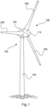
- Fig.1 shows a schematic representation of a wind turbine.
- Fig.1 shows a wind turbine 100 with a tower 102 and a nacelle 104.
- a rotor 106 with three rotor blades 200 and a spinner 110 is arranged on the nacelle 104.
- the rotor 106 is set in rotation by the wind and thereby drives a generator in the nacelle 104.
- Fig. 2 shows a schematic representation of a wind turbine during assembly of a rotor blade according to an embodiment of the invention.
- the wind turbine 100 has a tower 102, a nacelle 104 and a spinner 110.
- the rotor blade connections 111 are provided on the spinner.
- the rotor blade 200 has a rotor blade root 210 and a rotor blade tip 220.
- a lifting crossbeam 300 with a second hook 340 is lifted a rotor blade 200 in order to attach the rotor blade 200 to the spinner 110 of the wind turbine 100.
- the crane hook 410 is coupled to a lifting crossbeam 300 which has a second crane hook 340, via which the rotor blade 200 is lifted by means of lifting ropes 360.
- the crane 400 must therefore lift both the rotor blade 200 and the loading unit or lifting beam 300.
- a lifting beam with a loading unit 300 is used to increase the weight to be lifted by the crane 400.
- the invention is based on the idea of reducing the ratio between the area of the component to be assembled (here a rotor blade) and the weight of the component by increasing the weight to be lifted by the crane 400 by increasing the weight to be lifted by the loading weight of the loading unit 300. This ensures that the rotor blade can also be assembled at higher wind speeds.
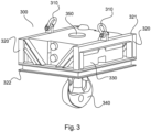
- Fig.3 shows a schematic representation of a lifting beam according to the invention.
- the lifting beam 300 has at least one, preferably two, suspension points 310 on its upper side, by means of which the lifting beam can be attached to a crane hook 410.
- the lifting beam 300 can have a frame 320 for receiving ballast weights 330.
- a second crane hook 340 is provided on the underside of the lifting beam 300, to which the lifting cables 360 for the rotor blade 200 can be attached.
- This second crane hook 340 can be designed to be rotatable.
- Attachment points 321 for guide cables can be provided on the frame 320.
- a securing unit 350 can be provided which secures the ballast weights 330 in the assembled state.
- the ballast weights 330 can be attached inside the frame.
- a storage option or storage unit 322 can be provided, by means of which the traverse can be placed on a floor even when the second crane hook 340 is mounted.
- a W A P * c W [Formula for calculating the wind attack area]
- a W 135 m 2 * 1.1
- a W 148.5 m 2
- V max V max tab ⁇ 1.2 m 2 t ⁇ m H
- a W [Formula for calculating the permissible wind speed]
- V max 1 9 m s ⁇ 1.2 m 2 t ⁇ 30 t 148.5 m 2
- V max 1 4.43 m s (Maximum permissible wind speed for the stroke of a rotor blade)
- a W 148.5 m 2 (Assumption that the wind attack area does not change, although there is a division between auxiliary winch and assembly crane)
- V max 2 9 m s ⁇ 1.2 m 2 t ⁇ 80 t 148.5 m 2 (Assumption that the assembly crane has a lifting capacity of 80t, which is also necessary for the assembly of the nacelle components)
- V max 2 7.24 m s (Maximum permissible wind speed for the lift of a rotor blade by using additional ballast)
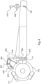
- Fig.4 shows a schematic representation of a part of a wind turbine according to a second embodiment of the invention.
- a spinner 110 of the wind turbine 100 is shown together with a winch unit 500.
- the winch unit 500 can be attached to the spinner 110 and has a frame 510, a winch 520 and two pulleys 531, 532.
- the winch unit 500 also has a hook 540.
- a rotor blade root 210 of a rotor blade 200 to be mounted can be attached to this hook 540, for example by means of a sling 550.
- a crane with its crane hook 410 can lift a lifting crossbeam 300 according to the first embodiment, which in turn is connected to the rotor blade 200 and in particular to a pick-up point 201 via a lifting cable.
- the rotor blade 200 is thus lifted by means of the crane and the winch unit 500.
- This is advantageous because it means that a guide with cable winches can be dispensed with. This proves particularly advantageous for forest locations.
- the maximum permissible speed can be increased considerably with the aid of the lifting beam when assembling the rotor blades.
- the maximum permissible wind speed can be increased from 4.4m 2 to 7.2m 2 .
- the winch unit according to one aspect of the present invention is used, the permissible wind speed can be increased to 8.5m/s. This is particularly advantageous because the rotor blade can thus also be assembled at higher wind speeds.
Landscapes
- Engineering & Computer Science (AREA)
- Mechanical Engineering (AREA)
- Life Sciences & Earth Sciences (AREA)
- Sustainable Development (AREA)
- Sustainable Energy (AREA)
- Chemical & Material Sciences (AREA)
- Combustion & Propulsion (AREA)
- General Engineering & Computer Science (AREA)
- Civil Engineering (AREA)
- Structural Engineering (AREA)
- Wind Motors (AREA)
- Load-Engaging Elements For Cranes (AREA)
Description
- Die vorliegende Erfindung betrifft ein Verfahren zum Errichten einer Windenergieanlage sowie eine Hebetraverse zur Montage eines Rotorblatts einer Windenergieanlage.
- Bei der Montage der Rotorblätter einer Windenergieanlage sind die Rotorblätter den Witterungsbedingungen ungeschützt ausgesetzt. Eine Montage von Rotorblättern einer Windenergieanlage ist gemäß EN 13000 nur bis zu einer bestimmten Windgeschwindigkeit zulässig. Sollte diese Windgeschwindigkeit überschritten werden, darf das Rotorblatt nicht montiert werden.
- In der prioritätsbegründenden deutschen Patentanmeldung hat das Deutsche Patent- und Markenamt das folgende Dokument recherchiert: Prospekt Rotorblatttraverse Ematec, 2014.
- Die Dokumente
EP 3 034 450 ,US 2016/002010 undGB 1 002 758 - Es ist somit eine Aufgabe der vorliegenden Erfindung ein Verfahren zum Errichten einer Windenergieanlage vorzusehen, welche auch bei höheren Windgeschwindigkeiten erfolgen kann.
- Diese Aufgabe wird durch ein Verfahren zum Errichten einer Windenergieanlage nach Anspruch 1 sowie durch eine Verwendung einer Hebetraverse nach Anspruch 4 gelöst.
- Damit wird ein Verfahren zum Errichten einer Windenergieanlage vorgesehen, welche einen aerodynamischen Rotor mit Rotorblattanschlüssen aufweist. Eine Hebetraverse weist eine Ballasteinheit auf und wird an einem Kranhaken eines Krans befestigt. Ein Rotorblatt wird mittels Hebeseile an einem zweiten Kranhaken an einer Unterseite der Ballasteinheit befestigt. Die Hebetraverse und das Rotorblatt werden durch den Kran zur Montage des Rotorblattes an einen der Rotorblattanschlüsse angehoben. Die Ballasteinheit dient dazu, das Gesamtgewicht der Hebetraverse zu erhöhen, damit ein Rotorblatt auch bei höheren Windgeschwindigkeiten montiert werden kann.
- Gemäß einem Aspekt der vorliegenden Erfindung weist die Ballasteinheit mindestens ein Ballastgewicht auf und das Ballastgewicht ist so ausgewählt, dass das Verhältnis zwischen der Fläche des Rotorblattes und der Summe aus dem Ballastgewicht und dem Gewicht des Rotorblattes ≤ 1 ist.
- Gemäß einem Aspekt der vorliegenden Erfindung wird eine Windeneinheit an dem Rotor der Windenergieanlage vorgesehen. An der Rotorblattwurzel des zu montierenden Rotorblattes wird an einem Haken der Windeneinheit befestigt. Das Rotorblatt wird mittels der Windeneinheit und dem Kran angehoben.
- Die vorliegende Erfindung betrifft ebenfalls die Verwendung einer Hebetraverse zur Montage eines Rotorblatts einer Windenergieanlage gemäß Anspruch 4. Die Hebetraverse weist eine Ballasteinheit und mindestens einen Einhängepunkt zur Aufnahme eines Kranhakens an einer Oberseite der Ballasteinheit auf. Ferner weist die Hebetraverse einen Haken an der Unterseite der Ballasteinheit und ein Ballastgewicht auf.
- Gemäß einem Aspekt der vorliegenden Erfindung wird ein Rotorblatt der Windenergieanlage über eine Hebetraverse an einen Kranhaken befestigt, um das Rotorblatt dann anschließend hochzuziehen. Die Hebetraverse weist eine Ballasteinheit mit mindestens einem Ballastgewicht auf. Die Verwendung von Ballastgewichten in der Hebetraverse bei der Montage der Rotorblätter dient dazu, das Gesamtgewicht (Rotorblätter + Traverse) zu erhöhen. Eine Erhöhung des durch den Kran zu transportierenden Gewichtes erscheint zunächst kontraproduktiv, hat jedoch den Vorteil, dass damit das Verhältnis zwischen der Fläche der Rotorblätter zu der Last der Rotorblätter erhöht wird.
- Die Formel zur Berechnung der maximal zulässigen Windgeschwindigkeiten bei der Montage der Rotorblätter hängt von dem verwendeten Mobilkran ab und wird nach EN13000 ermittelt. Insbesondere ist das Verhältnis Fläche des zu montierenden Bauteils zu der Last des Bauteils von großer Bedeutung. Bei der maximal zulässigen Windgeschwindigkeit darf das Verhältnis von Fläche zu Last nicht größer als 1 sein. Bei den modernen Rotorblättern von Windenergieanlagen kann dieses Verhältnis jedoch deutlich größer als 1 sein.
- Weitere Ausgestaltungen der Erfindung sind Gegenstand der Unteransprüche.
- Vorteile und Ausführungsbeispiele der Erfindung werden nachstehend unter Bezugnahme auf die Zeichnung näher erläutert.
- Fig. 1
- zeigt eine schematische Darstellung einer Windenergieanlage gemäß der Erfindung,
- Fig. 2
- zeigt eine schematische Darstellung einer Windenergieanlage bei der Montage eines Rotorblatts gemäß einem ersten Ausführungsbeispiels der Erfindung,
- Fig. 3
- zeigt eine schematische Darstelllung einer Hebetraverse gemäß der Erfindung und
- Fig. 4
- zeigt eine schematische Darstellung eines Teils einer Windenergieanlage gemäß einem zweiten Ausführungsbeispiel der Erfindung.
-
Fig. 1 zeigt eine schematische Darstellung einer Windenergieanlage.Fig. 1 zeigt eine Windenergieanlage 100 mit einem Turm 102 und einer Gondel 104. An der Gondel 104 ist ein Rotor 106 mit drei Rotorblättern 200 und einem Spinner 110 angeordnet. Der Rotor 106 wird im Betrieb durch den Wind in eine Drehbewegung versetzt und treibt dadurch einen Generator in der Gondel 104 an. -
Fig. 2 zeigt eine schematische Darstellung einer Windenergieanlage bei der Montage eines Rotorblattes gemäß einem Ausführungsbeispiel der Erfindung. Die Windenergieanlage 100 weist einen Turm 102, eine Gondel 104 und einen Spinner 110 auf. An dem Spinner sind die Rotorblattanschlüsse 111 vorgesehen. Das Rotorblatt 200 weist eine Rotorblattwurzel 210 und eine Rotorblattspitze 220 auf. Mittels eines Krans 400 und eines ersten Hakens (Kranhaken) 410 wird eine Hebetraverse 300 mit einem zweiten Haken 340 wird ein Rotorblatt 200 angehoben, um das Rotorblatt 200 an dem Spinner 110 der Windenergieanlage 100 zu befestigen. Der Kranhaken 410 ist mit einer Hebetraverse 300 gekoppelt, welche einen zweiten Kranhaken 340 aufweist, über welchen mittels Hebeseile 360 das Rotorblatt 200 angehoben wird. Der Kran 400 muss somit sowohl das Rotorblatt 200 als auch die Belasteinheit bzw. die Hebetraverse 300 anheben. - Gemäß der Erfindung wird eine Hebetraverse mit einer Belasteinheit 300 verwendet, um das durch den Kran 400 zu hebende Gewicht zu erhöhen. Die Erfindung beruht auf dem Gedanken, durch die Erhöhung des durch den Kran 400 zu hebenden Gewichts auch das Verhältnis zwischen der Fläche des zu montierenden Bauteils (hier ein Rotorblatt) zu dem Gewicht des Bauteils zu senken, in dem das zu hebende Gewicht durch das Belastgewicht der Belasteinheit 300 erhöht wird. Damit kann gewährleistet werden, dass das Rotorblatt auch bei höheren Windgeschwindigkeiten montiert werden kann.
-
Fig. 3 zeigt eine schematische Darstellung einer Hebetraverse gemäß der Erfindung. Die Hebetraverse 300 weist an ihrer oberen Seite mindestens ein, vorzugsweise zwei, Einhängpunkte 310 auf, mittels welcher die Hebetraverse an einem Kranhaken 410 zu befestigen ist. Optional kann die Hebetraverse 300 einen Rahmen 320 zur Aufnahme von Ballastgewichten 330 aufweisen. An der Unterseite der Hebetraverse 300 ist ein zweiter Kranhaken 340 vorgesehen, an welchem die Hebeseile 360 für das Rotorblatt 200 befestigt werden können. Dieser zweite Kranhaken 340 kann drehbar ausgestaltet sein. An dem Rahmen 320 können Anschlagpunkte 321 für Führungsseile vorgesehen sein. Gemäß einem Aspekt der vorliegenden Erfindung kann eine Sicherungseinheit 350 vorgesehen sein, welche die Ballastgewichte 330 im montierten Zustand sichert. - Die Ballastgewichte 330 können innerhalb des Rahmens befestigt werden.
- Gemäß einem Aspekt der vorliegenden Erfindung kann eine Abstellmöglichkeit oder bzw. Abstelleinheit 322 vorgesehen sein, mittels welcher die Traverse auch bei montiertem zweiten Kranhaken 340 auf einen Boden abgestellt werden kann.
- Nachfolgend wird die Berechnung der zulässigen Windgeschwindigkeit für den Hub eines Rotorblattes erläutert:
AW = AP * cW [Formel für die Berechnung der Windangriffsfläche] AW = 135m 2 * 1,1 AW = 148,5m 2 
[Formel zur Berechnung der zulässigen Windgeschwindigkeit] 

(Maximal zulässige Windgeschwindigkeit für den Hub eines Rotorblattes) - Die Berechnung der zulässigen Windgeschwindigkeit für den Hub eines Rotorblattes und der Erhöhung der Masse durch Verwendung einer zusätzlichen Traverse mit Ballastgewichten des Montagekrans erfolgt wie folgt:
AW = 148,5m 2 (Annahme, dass sich die Windangriffsfläche nicht ändert, obwohl sich eine Aufteilung zwischen Hilfswinde und Montagekran ergibt) 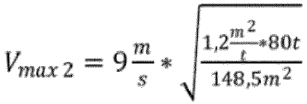
(Annahme, dass der Montagekran über eine Hubkraft von 80t verfügt, die auch für die Montage der Gondelkomponenten notwendig ist) 
(Maximal zulässige Windgeschwindigkeit für den Hub eines Rotorblattes durch Nutzung von Zusatzballast) -
Fig. 4 zeigt eine schematische Darstellung eines Teils einer Windenergieanlage gemäß einem zweiten Ausführungsbeispiel der Erfindung. InFig. 4 ist ein Spinner 110 der Windenergieanlage 100 zusammen mit einer Windeneinheit 500 gezeigt. Die Windeneinheit 500 kann an dem Spinner 110 befestigt und weist einen Rahmen 510, eine Winde 520 sowie zwei Umlenkrollen 531, 532 auf. Ferner weist die Windeneinheit 500 einen Haken 540 auf. An diesem Haken 540 kann eine Rotorblattwurzel 210 eines zu montierenden Rotorblattes 200, beispielsweise mittels einer Schlinge 550 befestigt werden. Ein Kran mit seinem Kranhaken 410 kann eine Hebetraverse 300 gemäß dem ersten Ausführungsbeispiel anheben, welche wiederum über ein Hebeseil mit dem Rotorblatt 200 und insbesondere einem Anpickpunkt 201 verbunden ist. Das Rotorblatt 200 wird somit mittels des Krans und der Windeneinheit 500 angehoben. Dies ist vorteilhaft, weil damit auf eine Führung mit Seilwinden verzichtet werden kann. Dies erweist sich insbesondere als vorteilhaft für Waldstandorte. - Die Berechnung der zulässigen Windgeschwindigkeit für den Hub eines Rotorblattes und der Erhöhung der Masse durch Verwendung einer zusätzlichen Traverse mit Ballastgewichten des Montagekrans und der Berücksichtigung der Lastaufteilung zwischen Hilfsvorrichtung und Montagekran erfolgt wie folgt:

(Annahme, das 1/3 der Fläche auf den Kran wirken) AW = 99m 2 A w2 = 5m 2 * 1,6 (Fläche der Traverse mit Zusatzballast) A W2 = 8m 2 

- Gemäß der Erfindung kann unter Zuhilfenahme der Hebetraverse bei der Montage der Rotorblätter die zulässige Maximalgeschwindigkeit erheblich gesteigert werden. Durch Verwendung der Hebetraverse mit der Ballasteinheit kann die maximal zulässige Windgeschwindigkeit von 4,4m2 auf 7,2m2 gesteigert werden. Wenn die Windeneinheit gemäß einem Aspekt der vorliegenden Erfindung verwendet wird, dann kann die zulässige Windgeschwindigkeit auf 8,5m/s gesteigert werden. Dies ist insbesondere vorteilhaft, weil somit das Rotorblatt auch bei höheren Windgeschwindigkeiten montiert werden kann.
Claims (4)
- Verfahren zum Errichten einer Windenergieanlage (100), welche einen aerodynamischen Rotor (110) mit Rotorblattanschlüssen (111) aufweist, mit den Schritten:Befestigen einer Ballasteinheit (300) an einer Hebetraverse (300),Befestigen der Hebetraverse (300) mit der Ballasteinheit (300) an einem Kranhaken (410) eines Krans (400),Befestigen eines Rotorblattes (200) mittels Hebeseile (360) an einem zweiten Kranhaken (340) an einer Unterseite der Ballasteinheit (300), undAnheben der Hebetraverse (300) mit der Ballasteinheit und des Rotorblattes (200) durch den Kran (400) zur Montage des Rotorblattes (200) an einen der Rotorblattanschlüsse (111),wobei die Ballasteinheit (300) mindestens ein Ballastgewicht (330) aufweist und das Ballastgewicht so gewählt ist, dass das Verhältnis in m2/t zwischen der Windangriffsfläche des Rotorblattes (200) und der Summe aus dem Ballastgewicht (330) und dem Gewicht des Rotorblattes (200) ≤ 1 ist.
- Verfahren nach Anspruch 1, ferner mit den Schritten:Vorsehen einer Windeneinheit (500) an dem Rotor (110) der Windenergieanlage (100),Befestigen einer Rotorblattwurzel (210) des zu montierenden Rotorblattes (200) an einem Haken (540) der Windeneinheit (500), undAnheben des Rotorblattes (200) mittels der Windeneinheit (500) und dem Kran (400).
- Verfahren nach Anspruch 1 oder 2,
wobei die Hebetraverse (300) einen Rahmen (330) zur Aufnahme des mindestens einen Ballastgewichtes (330) aufweist. - Verwendung einer Hebetraverse (300) zur Montage eines Rotorblattes (200) einer Windenergieanlage (100),wobei die Hebetraverse (300) eine Ballasteinheit (300) aufweist, die mindestens einen Einhängepunkt (310) zur Aufnahme eines Kranhakens (410) an einer Oberseite der Ballasteinheit (300), einen Haken (340) an der Unterseite der Ballasteinheit (300) und ein Ballastgewicht (330) aufweist,wobei die Ballasteinheit (300) mindestens ein Ballastgewicht (330) aufweist und das Ballastgewicht so gewählt ist, dass das Verhältnis in m2/t zwischen der Windangriffsfläche des Rotorblattes (200) und der Summe aus dem Ballastgewicht (330) und dem Gewicht des Rotorblattes (200) ≤ 1 ist,wobei das Rotorblatt (200) mittels der Hebetraverse (300) angehoben wird, um das Rotorblatt (200) an einem Rotorblattanschluss (111) zu montieren.
Applications Claiming Priority (2)
| Application Number | Priority Date | Filing Date | Title |
|---|---|---|---|
| DE102016111514.2A DE102016111514A1 (de) | 2016-06-23 | 2016-06-23 | Verfahren zum Errichten einer Windenergieanlage und Hebetraverse zur Montage eines Rotorblatts einer Windenergieanlage |
| PCT/EP2017/064869 WO2017220459A1 (de) | 2016-06-23 | 2017-06-19 | Verfahren zum errichten einer windenergieanlage und hebetraverse zur montage eines rotorblatts einer windenergieanlage |
Publications (3)
| Publication Number | Publication Date |
|---|---|
| EP3475558A1 EP3475558A1 (de) | 2019-05-01 |
| EP3475558B1 true EP3475558B1 (de) | 2024-09-04 |
| EP3475558C0 EP3475558C0 (de) | 2024-09-04 |
Family
ID=59070671
Family Applications (1)
| Application Number | Title | Priority Date | Filing Date |
|---|---|---|---|
| EP17730791.5A Active EP3475558B1 (de) | 2016-06-23 | 2017-06-19 | Verfahren zum errichten einer windenergieanlage und hebetraverse zur montage eines rotorblatts einer windenergieanlage |
Country Status (10)
| Country | Link |
|---|---|
| US (1) | US10823149B2 (de) |
| EP (1) | EP3475558B1 (de) |
| JP (1) | JP2019520509A (de) |
| KR (1) | KR102171624B1 (de) |
| CN (1) | CN109477457A (de) |
| BR (1) | BR112018072270A2 (de) |
| CA (1) | CA3024915A1 (de) |
| DE (1) | DE102016111514A1 (de) |
| RU (1) | RU2720731C1 (de) |
| WO (1) | WO2017220459A1 (de) |
Families Citing this family (3)
| Publication number | Priority date | Publication date | Assignee | Title |
|---|---|---|---|---|
| ES2947314T3 (es) | 2016-12-23 | 2023-08-04 | Vestas Wind Sys As | Método y conjunto para manipular palas de turbina eólica |
| DE102019106969A1 (de) * | 2019-03-19 | 2020-09-24 | Wobben Properties Gmbh | Verfahren zur Montage von Rotorblättern einer Windenergieanlage |
| CN114080498B (zh) * | 2019-06-11 | 2023-09-15 | 维斯塔斯风力系统有限公司 | 用于处理风力涡轮机部件的方法和相关的提升系统 |
Family Cites Families (29)
| Publication number | Priority date | Publication date | Assignee | Title |
|---|---|---|---|---|
| GB1002758A (en) * | 1962-11-20 | 1965-08-25 | C H Wheeler Mfg Co | Anti-pendulation device for jig cranes |
| US4950012A (en) * | 1989-06-19 | 1990-08-21 | Jones Harmon L | Universal accessories remover for locomotives |
| RU2235054C2 (ru) | 2002-04-11 | 2004-08-27 | Санкт-Петербургский государственный аграрный университет | Устройство для гашения колебаний груза, подвешенного на рабочих ветвях грузового каната стрелового крана |
| ES2257558T3 (es) | 2002-05-27 | 2006-08-01 | Vestas Wind Systems A/S | Metodos de manipulacion de palas de turbinas eolicas y de montaje de dichas palas en una turbina eolica, sistema y unidad de agarre para manipular una pala de turbina eolica. |
| DE10224439C5 (de) | 2002-06-01 | 2009-12-31 | Aloys Wobben | Verfahren zur Montage/Demontage von Komponenten einer Windenergieanlage |
| AU2002354242A1 (en) | 2002-12-19 | 2004-07-14 | Hhh Manufacturing Co. | Electric hoist |
| US7708325B2 (en) * | 2004-09-27 | 2010-05-04 | L-3 Communications Integrated Systems L.P. | Systems and methods for rotation of objects |
| JP2006152862A (ja) | 2004-11-26 | 2006-06-15 | Ishikawajima Harima Heavy Ind Co Ltd | 風力発電装置におけるブレードの取り付け方法及び取り外し方法 |
| EP1925582B1 (de) * | 2006-11-23 | 2010-06-23 | Siemens Aktiengesellschaft | Verfahren und Vorrichtung zur Montage von Windturbinenschaufeln |
| UA84787C2 (ru) | 2007-02-28 | 2008-11-25 | Евгений Сергеевич Изосимов | Способ монтажа многолопастного ротора ветродвигателя с прочным внешним кольцом аэродинамической формы |
| ES2563930T5 (es) * | 2007-06-15 | 2019-09-27 | Siemens Ag | Método para el montaje de al menos dos componentes de una turbina eólica y uso de un dispositivo de manipulación |
| JP4885073B2 (ja) | 2007-06-20 | 2012-02-29 | 三菱重工業株式会社 | 風車回転翼の吊下げ装置、風車回転翼の取付け方法、および風力発電装置の建設方法 |
| NL1035301C1 (nl) * | 2008-04-16 | 2008-06-04 | Dhlc | Lift- en daalmethode middels een demontabele hijsinrichting. |
| US20100254813A1 (en) * | 2009-04-02 | 2010-10-07 | Frontier Pro Services | Winch servicing of wind turbines |
| CN101565091B (zh) * | 2009-05-21 | 2011-06-15 | 上海利策科技有限公司 | 水上风力发电机的安装设备及其施工方法 |
| CN201593181U (zh) | 2009-10-16 | 2010-09-29 | 抚州市临川白勇海洋工程有限公司 | 自升式海上风电机组安装平台 |
| EP2436593B1 (de) * | 2010-10-01 | 2013-11-27 | Nordic Yards Holding GmbH | Schiff und Verfahren zum Befördern und Aufstellen von Offshore-Strukturen |
| WO2012114319A1 (en) * | 2011-02-27 | 2012-08-30 | Eitan Leibovitz | Lifting beam |
| DE102011084140A1 (de) * | 2011-10-07 | 2013-04-11 | Wobben Properties Gmbh | Verfahren und Vorrichtung zum Montieren eines Rotors einer Windenergieanlage |
| DK177554B1 (en) * | 2012-05-15 | 2013-10-07 | Envision Energy Denmark Aps | Method and equipment for turning a blade or a blade part for a wind turbine during production or installation |
| KR101334339B1 (ko) | 2012-06-19 | 2013-11-28 | 삼성중공업 주식회사 | 풍력발전기용 블레이드 그립핑 장치 |
| KR101358229B1 (ko) | 2012-06-25 | 2014-02-11 | 삼성중공업 주식회사 | 풍력발전기용 블레이드 그립핑 장치 |
| DE102014003906A1 (de) * | 2013-07-01 | 2015-01-08 | Liebherr-Werk Biberach Gmbh | Turmdrehkran |
| JP2015075037A (ja) | 2013-10-09 | 2015-04-20 | 三菱重工業株式会社 | 風車用のブレード着脱方法及びブレード着脱装置 |
| US9964095B2 (en) * | 2014-04-21 | 2018-05-08 | General Electric Company | Method and system for servicing wind turbine rotor |
| DK178141B1 (en) * | 2014-06-03 | 2015-06-22 | Envision Energy | Wind turbine blade lifting device and a method for lifting a wind turbine blade |
| US9346656B2 (en) * | 2014-07-01 | 2016-05-24 | Marvin M. May | Stabilization and control of a crane load |
| ES2675331T3 (es) * | 2014-12-19 | 2018-07-10 | Airbus Defence And Space, S.A. | Dispositivo para izar y controlar cargas |
| EP3081523B1 (de) * | 2015-04-15 | 2018-06-27 | Airbus Defence and Space, S.A. | Selbstausgleichende vorrichtung zum heben und positionieren von lasten mit sechs freiheitsgraden |
-
2016
- 2016-06-23 DE DE102016111514.2A patent/DE102016111514A1/de not_active Withdrawn
-
2017
- 2017-06-19 WO PCT/EP2017/064869 patent/WO2017220459A1/de not_active Ceased
- 2017-06-19 EP EP17730791.5A patent/EP3475558B1/de active Active
- 2017-06-19 CN CN201780038409.4A patent/CN109477457A/zh active Pending
- 2017-06-19 RU RU2019101041A patent/RU2720731C1/ru active
- 2017-06-19 CA CA3024915A patent/CA3024915A1/en not_active Abandoned
- 2017-06-19 BR BR112018072270-7A patent/BR112018072270A2/pt not_active Application Discontinuation
- 2017-06-19 US US16/309,028 patent/US10823149B2/en active Active
- 2017-06-19 JP JP2018559304A patent/JP2019520509A/ja active Pending
- 2017-06-19 KR KR1020197001053A patent/KR102171624B1/ko active Active
Also Published As
| Publication number | Publication date |
|---|---|
| CA3024915A1 (en) | 2017-12-28 |
| KR20190018490A (ko) | 2019-02-22 |
| KR102171624B1 (ko) | 2020-10-29 |
| US20190309730A1 (en) | 2019-10-10 |
| EP3475558C0 (de) | 2024-09-04 |
| WO2017220459A1 (de) | 2017-12-28 |
| RU2720731C1 (ru) | 2020-05-13 |
| JP2019520509A (ja) | 2019-07-18 |
| BR112018072270A2 (pt) | 2019-02-12 |
| DE102016111514A1 (de) | 2017-12-28 |
| CN109477457A (zh) | 2019-03-15 |
| EP3475558A1 (de) | 2019-05-01 |
| US10823149B2 (en) | 2020-11-03 |
Similar Documents
| Publication | Publication Date | Title |
|---|---|---|
| DE60011737T3 (de) | Methode zum Montieren der Komponenten einer Windkraftanlage | |
| EP1516119B1 (de) | Verfahren zur montage/demontage von komponenten einer windenergieanlage | |
| DE10205988B4 (de) | Windenergieanlage | |
| EP2163504B1 (de) | Verfahren zum Hochheben von Komponenten von Windenenergieanlagen | |
| EP3048299B1 (de) | Lastaufnahmemittel für einen turm oder eine turmsektion einer windenergieanlage und verfahren zum errichten einer windenergieanlage | |
| DE102009056245B4 (de) | Windenergieanlage mit Hebevorrichtung | |
| EP2764237B1 (de) | Verfahren und vorrichtung zum montieren eines rotors einer windenergieanlage | |
| EP3710694B1 (de) | Flanschgestell und montageset zur vormontage und/oder zum transport und/oder zur montage eines turmsegments für eine windenergieanlage sowie verfahren | |
| WO2013110417A1 (de) | Verfahren und vorrichtung zum montieren einer rotornabe einer windenenergieanlage | |
| EP3475558B1 (de) | Verfahren zum errichten einer windenergieanlage und hebetraverse zur montage eines rotorblatts einer windenergieanlage | |
| DE102013208760A1 (de) | Windenergieanlage und Windenergieanlagen-Turm | |
| EP2723670A1 (de) | Lasthandhabungsvorrichtung zum anheben und verfahren zur montage von rotorblättern einer windenergieanlage | |
| DE102018124084A1 (de) | Verfahren zum Betreiben einer Windenergieanlage, Windenergieanlage und Windpark | |
| DE102015216444A1 (de) | Windenergieanlage | |
| DE202017107301U1 (de) | Turmdrehkran | |
| EP3519634B1 (de) | Offshore-windenergieanlage | |
| EP2279979B1 (de) | Vorrichtung zur Vormontage, Zwischenlagerung und zum Transport grosser Bauteile, insbesondere Bauteile von Windenergieanlagen | |
| DE102009000963A1 (de) | Verfahren und Fördermittel zur Montage eines Turms sowie Turmsegment | |
| DE202011001850U1 (de) | Kran | |
| EP3404259A1 (de) | Verfahren, lastaufnahmemittel und montagesystem zum zusammenbauen einer windenergieanlage | |
| DE102009023538A1 (de) | Turm einer Windkraftanlage, Windkraftanlage sowie Verfahren zum Anheben von Komponenten einer Windkraftanlage | |
| WO2008009352A9 (de) | Anordnung einer hebeeinrichtung an einem rotorblatt einer windenergieanlage sowie verfahren | |
| DE102019219722A1 (de) | Verfahren zum Errichten einer Windenergieanlage | |
| WO2004076781A1 (de) | Vorrichtung zur errichtung einer windenergieanlage | |
| DE202018006613U1 (de) | Vorrichtung zur Montage von Teilen hoher und extra hoher Türme |
Legal Events
| Date | Code | Title | Description |
|---|---|---|---|
| STAA | Information on the status of an ep patent application or granted ep patent |
Free format text: STATUS: UNKNOWN |
|
| STAA | Information on the status of an ep patent application or granted ep patent |
Free format text: STATUS: THE INTERNATIONAL PUBLICATION HAS BEEN MADE |
|
| PUAI | Public reference made under article 153(3) epc to a published international application that has entered the european phase |
Free format text: ORIGINAL CODE: 0009012 |
|
| STAA | Information on the status of an ep patent application or granted ep patent |
Free format text: STATUS: REQUEST FOR EXAMINATION WAS MADE |
|
| 17P | Request for examination filed |
Effective date: 20190123 |
|
| AK | Designated contracting states |
Kind code of ref document: A1 Designated state(s): AL AT BE BG CH CY CZ DE DK EE ES FI FR GB GR HR HU IE IS IT LI LT LU LV MC MK MT NL NO PL PT RO RS SE SI SK SM TR |
|
| AX | Request for extension of the european patent |
Extension state: BA ME |
|
| DAV | Request for validation of the european patent (deleted) | ||
| DAX | Request for extension of the european patent (deleted) | ||
| STAA | Information on the status of an ep patent application or granted ep patent |
Free format text: STATUS: EXAMINATION IS IN PROGRESS |
|
| 17Q | First examination report despatched |
Effective date: 20200914 |
|
| GRAP | Despatch of communication of intention to grant a patent |
Free format text: ORIGINAL CODE: EPIDOSNIGR1 |
|
| STAA | Information on the status of an ep patent application or granted ep patent |
Free format text: STATUS: GRANT OF PATENT IS INTENDED |
|
| RIC1 | Information provided on ipc code assigned before grant |
Ipc: B66C 23/20 20060101ALI20240402BHEP Ipc: B66C 1/34 20060101ALI20240402BHEP Ipc: B66C 13/06 20060101ALI20240402BHEP Ipc: F03D 13/10 20160101ALI20240402BHEP Ipc: F03D 1/06 20060101AFI20240402BHEP |
|
| INTG | Intention to grant announced |
Effective date: 20240417 |
|
| GRAS | Grant fee paid |
Free format text: ORIGINAL CODE: EPIDOSNIGR3 |
|
| GRAA | (expected) grant |
Free format text: ORIGINAL CODE: 0009210 |
|
| STAA | Information on the status of an ep patent application or granted ep patent |
Free format text: STATUS: THE PATENT HAS BEEN GRANTED |
|
| AK | Designated contracting states |
Kind code of ref document: B1 Designated state(s): AL AT BE BG CH CY CZ DE DK EE ES FI FR GB GR HR HU IE IS IT LI LT LU LV MC MK MT NL NO PL PT RO RS SE SI SK SM TR |
|
| REG | Reference to a national code |
Ref country code: GB Ref legal event code: FG4D Free format text: NOT ENGLISH |
|
| REG | Reference to a national code |
Ref country code: CH Ref legal event code: EP |
|
| REG | Reference to a national code |
Ref country code: IE Ref legal event code: FG4D Free format text: LANGUAGE OF EP DOCUMENT: GERMAN |
|
| REG | Reference to a national code |
Ref country code: DE Ref legal event code: R096 Ref document number: 502017016406 Country of ref document: DE |
|
| U01 | Request for unitary effect filed |
Effective date: 20240904 |
|
| U07 | Unitary effect registered |
Designated state(s): AT BE BG DE DK EE FI FR IT LT LU LV MT NL PT RO SE SI Effective date: 20240920 |
|
| PG25 | Lapsed in a contracting state [announced via postgrant information from national office to epo] |
Ref country code: NO Free format text: LAPSE BECAUSE OF FAILURE TO SUBMIT A TRANSLATION OF THE DESCRIPTION OR TO PAY THE FEE WITHIN THE PRESCRIBED TIME-LIMIT Effective date: 20241204 |
|
| PG25 | Lapsed in a contracting state [announced via postgrant information from national office to epo] |
Ref country code: GR Free format text: LAPSE BECAUSE OF FAILURE TO SUBMIT A TRANSLATION OF THE DESCRIPTION OR TO PAY THE FEE WITHIN THE PRESCRIBED TIME-LIMIT Effective date: 20241205 Ref country code: PL Free format text: LAPSE BECAUSE OF FAILURE TO SUBMIT A TRANSLATION OF THE DESCRIPTION OR TO PAY THE FEE WITHIN THE PRESCRIBED TIME-LIMIT Effective date: 20240904 |
|
| PG25 | Lapsed in a contracting state [announced via postgrant information from national office to epo] |
Ref country code: HR Free format text: LAPSE BECAUSE OF FAILURE TO SUBMIT A TRANSLATION OF THE DESCRIPTION OR TO PAY THE FEE WITHIN THE PRESCRIBED TIME-LIMIT Effective date: 20240904 |
|
| PG25 | Lapsed in a contracting state [announced via postgrant information from national office to epo] |
Ref country code: ES Free format text: LAPSE BECAUSE OF FAILURE TO SUBMIT A TRANSLATION OF THE DESCRIPTION OR TO PAY THE FEE WITHIN THE PRESCRIBED TIME-LIMIT Effective date: 20240904 Ref country code: RS Free format text: LAPSE BECAUSE OF FAILURE TO SUBMIT A TRANSLATION OF THE DESCRIPTION OR TO PAY THE FEE WITHIN THE PRESCRIBED TIME-LIMIT Effective date: 20241204 |
|
| PG25 | Lapsed in a contracting state [announced via postgrant information from national office to epo] |
Ref country code: RS Free format text: LAPSE BECAUSE OF FAILURE TO SUBMIT A TRANSLATION OF THE DESCRIPTION OR TO PAY THE FEE WITHIN THE PRESCRIBED TIME-LIMIT Effective date: 20241204 Ref country code: PL Free format text: LAPSE BECAUSE OF FAILURE TO SUBMIT A TRANSLATION OF THE DESCRIPTION OR TO PAY THE FEE WITHIN THE PRESCRIBED TIME-LIMIT Effective date: 20240904 Ref country code: NO Free format text: LAPSE BECAUSE OF FAILURE TO SUBMIT A TRANSLATION OF THE DESCRIPTION OR TO PAY THE FEE WITHIN THE PRESCRIBED TIME-LIMIT Effective date: 20241204 Ref country code: HR Free format text: LAPSE BECAUSE OF FAILURE TO SUBMIT A TRANSLATION OF THE DESCRIPTION OR TO PAY THE FEE WITHIN THE PRESCRIBED TIME-LIMIT Effective date: 20240904 Ref country code: GR Free format text: LAPSE BECAUSE OF FAILURE TO SUBMIT A TRANSLATION OF THE DESCRIPTION OR TO PAY THE FEE WITHIN THE PRESCRIBED TIME-LIMIT Effective date: 20241205 Ref country code: ES Free format text: LAPSE BECAUSE OF FAILURE TO SUBMIT A TRANSLATION OF THE DESCRIPTION OR TO PAY THE FEE WITHIN THE PRESCRIBED TIME-LIMIT Effective date: 20240904 |
|
| PG25 | Lapsed in a contracting state [announced via postgrant information from national office to epo] |
Ref country code: IS Free format text: LAPSE BECAUSE OF FAILURE TO SUBMIT A TRANSLATION OF THE DESCRIPTION OR TO PAY THE FEE WITHIN THE PRESCRIBED TIME-LIMIT Effective date: 20250104 |
|
| PG25 | Lapsed in a contracting state [announced via postgrant information from national office to epo] |
Ref country code: SM Free format text: LAPSE BECAUSE OF FAILURE TO SUBMIT A TRANSLATION OF THE DESCRIPTION OR TO PAY THE FEE WITHIN THE PRESCRIBED TIME-LIMIT Effective date: 20240904 |
|
| PG25 | Lapsed in a contracting state [announced via postgrant information from national office to epo] |
Ref country code: CZ Free format text: LAPSE BECAUSE OF FAILURE TO SUBMIT A TRANSLATION OF THE DESCRIPTION OR TO PAY THE FEE WITHIN THE PRESCRIBED TIME-LIMIT Effective date: 20240904 |
|
| PG25 | Lapsed in a contracting state [announced via postgrant information from national office to epo] |
Ref country code: SK Free format text: LAPSE BECAUSE OF FAILURE TO SUBMIT A TRANSLATION OF THE DESCRIPTION OR TO PAY THE FEE WITHIN THE PRESCRIBED TIME-LIMIT Effective date: 20240904 |
|
| U20 | Renewal fee for the european patent with unitary effect paid |
Year of fee payment: 9 Effective date: 20250521 |
|
| PLBE | No opposition filed within time limit |
Free format text: ORIGINAL CODE: 0009261 |
|
| STAA | Information on the status of an ep patent application or granted ep patent |
Free format text: STATUS: NO OPPOSITION FILED WITHIN TIME LIMIT |
|
| 26N | No opposition filed |
Effective date: 20250605 |
|
| REG | Reference to a national code |
Ref country code: CH Ref legal event code: H13 Free format text: ST27 STATUS EVENT CODE: U-0-0-H10-H13 (AS PROVIDED BY THE NATIONAL OFFICE) Effective date: 20260127 |
|
| PG25 | Lapsed in a contracting state [announced via postgrant information from national office to epo] |
Ref country code: MC Free format text: LAPSE BECAUSE OF FAILURE TO SUBMIT A TRANSLATION OF THE DESCRIPTION OR TO PAY THE FEE WITHIN THE PRESCRIBED TIME-LIMIT Effective date: 20240904 |