EP3473368A1 - Gas-shielded arc welding method and method for manufacturing welded structure - Google Patents
Gas-shielded arc welding method and method for manufacturing welded structure Download PDFInfo
- Publication number
- EP3473368A1 EP3473368A1 EP17815333.4A EP17815333A EP3473368A1 EP 3473368 A1 EP3473368 A1 EP 3473368A1 EP 17815333 A EP17815333 A EP 17815333A EP 3473368 A1 EP3473368 A1 EP 3473368A1
- Authority
- EP
- European Patent Office
- Prior art keywords
- welding
- consumable electrode
- gas
- less
- content
- Prior art date
- Legal status (The legal status is an assumption and is not a legal conclusion. Google has not performed a legal analysis and makes no representation as to the accuracy of the status listed.)
- Granted
Links
Images
Classifications
-
- B—PERFORMING OPERATIONS; TRANSPORTING
- B23—MACHINE TOOLS; METAL-WORKING NOT OTHERWISE PROVIDED FOR
- B23K—SOLDERING OR UNSOLDERING; WELDING; CLADDING OR PLATING BY SOLDERING OR WELDING; CUTTING BY APPLYING HEAT LOCALLY, e.g. FLAME CUTTING; WORKING BY LASER BEAM
- B23K9/00—Arc welding or cutting
- B23K9/16—Arc welding or cutting making use of shielding gas
- B23K9/173—Arc welding or cutting making use of shielding gas and of a consumable electrode
-
- B—PERFORMING OPERATIONS; TRANSPORTING
- B23—MACHINE TOOLS; METAL-WORKING NOT OTHERWISE PROVIDED FOR
- B23K—SOLDERING OR UNSOLDERING; WELDING; CLADDING OR PLATING BY SOLDERING OR WELDING; CUTTING BY APPLYING HEAT LOCALLY, e.g. FLAME CUTTING; WORKING BY LASER BEAM
- B23K35/00—Rods, electrodes, materials, or media, for use in soldering, welding, or cutting
- B23K35/22—Rods, electrodes, materials, or media, for use in soldering, welding, or cutting characterised by the composition or nature of the material
- B23K35/24—Selection of soldering or welding materials proper
- B23K35/30—Selection of soldering or welding materials proper with the principal constituent melting at less than 1550°C
-
- B—PERFORMING OPERATIONS; TRANSPORTING
- B23—MACHINE TOOLS; METAL-WORKING NOT OTHERWISE PROVIDED FOR
- B23K—SOLDERING OR UNSOLDERING; WELDING; CLADDING OR PLATING BY SOLDERING OR WELDING; CUTTING BY APPLYING HEAT LOCALLY, e.g. FLAME CUTTING; WORKING BY LASER BEAM
- B23K35/00—Rods, electrodes, materials, or media, for use in soldering, welding, or cutting
- B23K35/22—Rods, electrodes, materials, or media, for use in soldering, welding, or cutting characterised by the composition or nature of the material
- B23K35/24—Selection of soldering or welding materials proper
- B23K35/32—Selection of soldering or welding materials proper with the principal constituent melting at more than 1550°C
-
- B—PERFORMING OPERATIONS; TRANSPORTING
- B23—MACHINE TOOLS; METAL-WORKING NOT OTHERWISE PROVIDED FOR
- B23K—SOLDERING OR UNSOLDERING; WELDING; CLADDING OR PLATING BY SOLDERING OR WELDING; CUTTING BY APPLYING HEAT LOCALLY, e.g. FLAME CUTTING; WORKING BY LASER BEAM
- B23K35/00—Rods, electrodes, materials, or media, for use in soldering, welding, or cutting
- B23K35/22—Rods, electrodes, materials, or media, for use in soldering, welding, or cutting characterised by the composition or nature of the material
- B23K35/38—Selection of media, e.g. special atmospheres for surrounding the working area
-
- B—PERFORMING OPERATIONS; TRANSPORTING
- B23—MACHINE TOOLS; METAL-WORKING NOT OTHERWISE PROVIDED FOR
- B23K—SOLDERING OR UNSOLDERING; WELDING; CLADDING OR PLATING BY SOLDERING OR WELDING; CUTTING BY APPLYING HEAT LOCALLY, e.g. FLAME CUTTING; WORKING BY LASER BEAM
- B23K9/00—Arc welding or cutting
- B23K9/02—Seam welding; Backing means; Inserts
- B23K9/025—Seam welding; Backing means; Inserts for rectilinear seams
-
- B—PERFORMING OPERATIONS; TRANSPORTING
- B23—MACHINE TOOLS; METAL-WORKING NOT OTHERWISE PROVIDED FOR
- B23K—SOLDERING OR UNSOLDERING; WELDING; CLADDING OR PLATING BY SOLDERING OR WELDING; CUTTING BY APPLYING HEAT LOCALLY, e.g. FLAME CUTTING; WORKING BY LASER BEAM
- B23K9/00—Arc welding or cutting
- B23K9/23—Arc welding or cutting taking account of the properties of the materials to be welded
-
- C—CHEMISTRY; METALLURGY
- C22—METALLURGY; FERROUS OR NON-FERROUS ALLOYS; TREATMENT OF ALLOYS OR NON-FERROUS METALS
- C22C—ALLOYS
- C22C38/00—Ferrous alloys, e.g. steel alloys
Definitions
- the present invention relates to a gas-shielded arc welding method and a method for manufacturing a welded structure.
- the reason why the fatigue strength of the welded part is lower than that of the base metal is mainly attributed to stress concentration at weld toe and tensile residual stress caused by the expansion and contraction due to welding heat, and improvements have been attempted by various means.
- Patent Document 1 discloses an iron-based consumable welding material having excellent fatigue strength in a welded joint portion, in which the contents of C and Mn are adjusted to specific ranges and predetermined amounts of S and Si are added.
- Patent Document 2 discloses a technique of reducing the martensite transformation point (Ms point) and reducing the tensile residual stress by containing a large amount of Ni in the flux-cored wire.
- Patent Document 3 discloses a flux-cored wire containing a large amount of Mn and Mo added, for the purpose of improving the fatigue property of the welded part of the high-strength steel having a tensile strength exceeding 490 MPa.
- Mn and Si are easily oxidizable components and form slag which is hardly peeled off on surfaces of beads.
- coating is usually performed, but it is difficult to peel off the slag remaining on the surfaces of the beads, so that coating is applied to the slag. Therefore, there is a problem that rust originated from the peeling site thereof occurs when the slag is peeled off after coating.
- Ni and Mo are expensive elements, there is a problem that cost increases due to the addition of large amounts of Ni and Mo.
- an object of the present invention is to provide: a gas-shielded arc welding method by which a high-tensile steel plate, particularly a steel plate having a tensile strength of 780 MPa or more can be welded at low cost, excellent fatigue resistance of the welded part and excellent corrosion resistance (coating property) of the welded part can be achieved; and a method for manufacturing a welded structure.
- the present invention relates to a gas-shielded arc welding method including welding a steel plate having a tensile strength of 780 MPa or more while feeding a consumable electrode via a welding torch and flowing a shielding gas, wherein:
- [Cr] represents the content (mass%) of Cr in the consumable electrode
- [CO 2 +O 2 ] represents a total content (vol.%) of at least one selected from CO 2 and O 2 in the shielding gas.
- welding is performed under the condition satisfying the following relationship (2). 0 ⁇ 900 ⁇ C + 1 / 4 Si + 1 / 2 Mn + 1 / 25 Cr ⁇ 0.8 ⁇ CO 2 + O 2 / 100 ⁇ TS ⁇ 50 / 3
- [C], [Si], [Mn] and [Cr] represent the contents (mass%) of C, Si, Mn and Cr, respectively, in the consumable electrode
- [CO 2 +O 2 ] represents the total content (vol.%) of at least one selected from CO 2 and O 2 in the shielding gas
- TS represents the tensile strength (MPa) of the steel plate.
- the consumable electrode may further include, in mass% based on the total mass of the consumable electrode, at least one selected from the group consisting of Mo: 0.10% or less, V: 0.10% or less, Nb: 0.10% or less, and Cu: 0.50% or less.
- the steel plate has a thickness of 1.0 mm to 3.6 mm, and lap fillet welding in which a plurality of the steel plates are lapped and welded is performed.
- the present invention also relates to a method for manufacturing a welded structure, including using the gas-shielded arc welding method, wherein a flank angle at a weld bead toe of the welded structure is 130° to 150°.
- a welded part excellent in fatigue resistance and corrosion resistance (coating property) can be obtained, and welding can be performed at low cost.
- the gas-shielded arc welding method in the present embodiment is a gas-shielded arc welding method including welding a steel plate having a tensile strength of 780 MPa or more while feeding a consumable electrode via a welding torch and flowing a shielding gas, and the consumable electrode includes, in mass% based on a total mass of the consumable electrode, C: 0 to 0.20%, Si: 0 to 0.50%, Mn: 0 to 0.50%, Cr: 1.00% to 9.00%, S: 0.0020% to 0.0600%, and Ni: 0 to 0.50%; the shielding gas comprises, in vol.%, at least one selected from CO 2 and O 2 : 1% to 15% in total, with the remainder being Ar and unavoidable impurities; welding is performed under the condition satisfying the following relationship (1).
- the welding apparatus used in the gas-shielded arc welding method in the present embodiment (hereinafter, sometimes simply referred to as a welding method of the present embodiment) is described.
- the welding apparatus is not particularly limited as long as the welding apparatus can perform gas-shielded arc welding, and the welding apparatus used in conventional gas-shielded arc welding can be used without particular limitation.
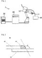
- FIG. 1 shows one embodiment of a welding apparatus used in the welding method of the present embodiment.
- the welding apparatus 1 includes: a robot 10 having a welding torch 11 attached to a tip thereof and allowing the welding torch 11 to move along a welding line of a material to be welded W (hereinafter sometimes referred to as "work" or “base metal”); a wire supply portion (not shown) that supplies a welding wire to the welding torch 11; and a welding power supply portion 30 that supplies current to a consumable electrode via the wire supply portion to generate arc between the consumable electrode and the material to be welded.
- the welding apparatus also includes a robot control portion 20 that controls robot operation for moving the welding torch 11.
- a steel plate having a tensile strength of 780 MPa or more is welded while feeding the consumable electrode via the welding torch and flowing a shielding gas.
- a kind of a consumable electrode may be a solid wire which is a steel wire, or may be a flux-cored welding wire composed of a steel sheath having a tubular shape and a flux with which the inner side of the sheath is filled, and the kind is not particularly limited, but the kind of the consumable electrode is preferably a solid wire.
- the consumable electrode may be in any form of a seamless type having no seam in the sheath or a seam type having a seam on the sheath.
- copper plating may or may not be applied to the surface of the welding wire (the outer side of the sheath in the case where the consumable electrode is a flux-cored welding wire).
- the reasons for limiting a numerical value of an amount of each component contained in the consumable electrode (welding wire) used in the welding method of the present embodiment are described below.
- the amount of each component in the following is the content per the total mass of the consumable electrode (welding wire).
- the percentage based on mass (mass%) is synonymous with the percentage based on weight (wt.%).
- C is an element effective for increasing the strength of the weld metal, but is an element harmful to hot cracking. Therefore, from the viewpoint of preventing hot cracking, the content of C is 0.20% or less, preferably 0.15% or less, more preferably 0.12% or less. On the other hand, from the viewpoint of improving the strength of the weld metal, the content of C is preferably 0.01% or more.
- Si is an element which reduces the surface tension of the weld metal and improves the bead shape, but Si is a component which is easily oxidized, and is also an element which generates slag hardly peeled off from the surfaces of the beads. Therefore, from the viewpoint of preventing generation of slag and improving the coating property, the content of Si is 0.50% or less, preferably 0.40% or less. On the other hand, Si may not be contained, but in the case of containing Si, the content of Si is preferably 0.01 % or more from the viewpoint of the bead shape.
- Mn is an element effective for ensuring the hardenability of the weld metal and enhancing the strength of the weld metal, but Mn is a component which is easily oxidized and is also an element which generates slag hardly peeled off from the surfaces of the beads. Therefore, from the viewpoint of preventing generation of slag and improving the coating property, the content of Mn is 0.50% or less, preferably 0.40% or less. On the other hand, Mn may not be contained, but in the case of containing Mn, the content of Mn is preferably 0.01% or more from improving the strength of the weld metal.
- Cr is an element effective for increasing the strength of the weld metal, reducing the Ms point to reduce the tensile residual stress, and improving the fatigue resistance of the welded part.
- Cr also contributes not only to the improvement of the arc stability during welding but also to improvement of the corrosion resistance of the weld metal.
- Cr is inexpensive as compared to Ni, Mo, and the like, and is advantageous from the viewpoint of cost. Therefore, from the viewpoint of effectively obtaining these effects, the content of Cr is 1.00% or more, preferably 2.50% or more, more preferably 4.00% or more.
- the content of Cr is increased, there is a possibility of hot cracking, so that the content of Cr is set to 9.00% or less.
- the content of Cr is preferably 7.50% or less, more preferably 6.50% or less.
- the content of S is 0.0020% or more, preferably 0.0050% or more, more preferably 0.0200% or more.
- the content of S is set to 0.0600% or less.
- the content of S is preferably 0.0500% or less, more preferably 0.0400% or less.
- Ni is an element effective for lowering the Ms point, but is very expensive. In addition, when Ni is contained excessively, cracking may occur at the terminal end of the weld metal. Therefore, from the viewpoint of cost reduction and cracking prevention at the terminal end, the content of Ni is 0.50% or less, preferably 0.30% or less, more preferably 0.20% or less. Ni may not be contained, but in the case of containing Ni, the lower limit of the content of Ni is, for example, 0.10%.
- the consumable electrode (welding wire) of the present embodiment may further contain components (optional components) such as Mo, V, and Nb in addition to the above-mentioned components (basic components).
- optional components such as Mo, V, and Nb in addition to the above-mentioned components (basic components).
- Mo is an element effective for increasing the strength by enhancing the hardenability, but is very expensive. In addition, when Mo is contained excessively, cracking may occur at the terminal end of the weld metal. Therefore, when Mo is added, from the viewpoint of cost reduction and cracking prevention at the terminal end, the content of Mo is 0.10% or less. The content of Mo is preferably 0.05% or less, more preferably 0.02% or less. Mo may not be contained.
- V is an element effective for increasing the strength by enhancing the hardenability, but it is fear that the weld metal is hardened and the toughness is deteriorated to cause cracks due to the precipitation of a carbide when V is contained excessively. Therefore, when V is added, from the viewpoint of cracking prevention, the content of V is 0.10% or less. The content of V is preferably 0.05% or less, more preferably 0.02% or less. V may not be contained.
- Nb is an element effective for increasing the strength by enhancing the hardenability, but it is fear that the weld metal is hardened and the toughness is deteriorated to cause cracks due to the precipitation of a carbide when Nb is contained excessively. Therefore, when Nb is added, from the viewpoint of cracking prevention, the content of Nb is 0.10% or less.
- the content of Nb is preferably 0.05% or less, more preferably 0.02% or less. Nb may not be contained.
- Cu is contained in copper plating applied to the wire surface for stabilizing energization from the welding tip to the welding wire.
- the wire used in the welding method of the present embodiment does not necessarily require copper plating, in the case where the copper plating is applied to the wire surface, it is preferable to set the content of Cu to 0.005% or more and 0.50% or less.
- the basic components and optional components in the consumable electrode (welding wire) used in the welding method of the present embodiment are as described above and the remainder substantially consists of Fe.
- substantially consist of Fe means that inclusion of trace amount of component(s) which does not inhibit properties thereof is permitted besides Fe, and examples of such trace component(s) include unavoidable impurities such as O, N and P.
- the components may correspond to unavoidable impurities.
- the shielding gas used in the welding method of the present embodiment contains, in vol.%, at least one selected from CO 2 and O 2 in a total amount of 1% to 15%, and the remainder being Ar and unavoidable impurities.
- the unavoidable impurities include N 2 , H 2 and the like, but it is preferable that the shielding gas contains no unavoidable impurities (0 vol.%).
- the total content of at least one selected from CO 2 and O 2 (hereinafter also referred to as content of CO 2 +O 2 ) in the shielding gas is 1% to 15% (vol.%).
- content of CO 2 +O 2 is 15% or less, the occurrence of slag can be effectively prevented and the coating property can be improved.
- the content of CO 2 +O 2 is preferably 10% or less, more preferably 7% or less.
- the content of CO 2 +O 2 is 1% or more, preferably 2% or more, more preferably 3% or more. Only CO 2 may be added, only O 2 may be added, or both CO 2 and O 2 may be added to the shielding gas. 1 ⁇ ⁇ 0.05 ⁇ CO 2 + O 2 + Cr ⁇ 8.3
- the relationship (1) is a relational expression for estimating the content of Cr remaining in the weld metal in consideration of the influence of the content of CO 2 +O 2 in the shielding gas.
- " ⁇ -0.05 ⁇ [CO 2 +O 2 ] ⁇ +[Cr]” may be abbreviated as A in some cases. 1 ⁇ ⁇ 0.05 ⁇ CO 2 + O 2 + Cr ⁇ 8.3
- [Cr] represents the content (mass%) of Cr in the consumable electrode
- [CO 2 +O 2 ] represents the total content (vol.%) of at least one selected from CO 2 and O 2 in the shielding gas.
- A When A is 1 or more, the effect of improving the fatigue resistance of the weld metal is effectively exhibited.
- A is preferably 2.5 or more, more preferably 4.0 or more.
- A When A is 8.3 or less, occurrence of cracking of the weld metal can be effectively prevented.
- A is preferably 7.0 or less, more preferably 6.0 or less. 0 ⁇ 900 ⁇ C + 1 / 4 Si + 1 / 2 Mn + 1 / 25 Cr ⁇ 0.8 ⁇ CO 2 + O 2 / 100 ⁇ TS ⁇ 50 / 3
- the welding method of the present embodiment welding is performed under the condition satisfying the following relationship (2).
- the relationship (2) is a relational expression considering the balance between the hardness of the base metal (steel plate) and the hardness of the welded part.
- "900 ⁇ ([C]+1/4[Si]+1/2[Mn]+]/25[Cr]) ⁇ (0,8-[CO 2 +O 2 ]/100)-(TS-50)/3" may be abbreviated as B in some cases.
- B When B is 0 or more, breakage at the interface between the weld metal and the base metal and breakage in the weld metal can be prevented effectively, and such a case is preferable.
- B is more preferably 15 or more, and still more preferably 30 or more.
- the stress generated on the steel material side when the weld metal expands is the compressive stress due to the reactive force to the weld metal.
- the higher the strength steel plate which can expect higher reactive force the greater the improvement of the fatigue property.
- the reactive force must also be lowered, and there is a danger of returning to the tensile stress state again due to the thermal contraction after the end of the transformation. If the tensile stress remains, improvement of fatigue strength cannot be expected.
- the strength (tensile strength) of the applied base metal is 780 MPa or more as the lower limit at which improvement of fatigue strength can be expected.
- the limitation of the upper limit of the strength of the base metal is not particularly needed.
- the maximum strength is about 1500 MPa, and to this extent, it is possible to improve the fatigue strength by the welding method of the present embodiment and overmatching of the weld metal can be achieved in terms of joint tensile strength.
- the tensile strength of the steel plate can be determined by the method specified in JIS Z2241.
- the thickness of the steel plate is not particularly limited, but in the case of lap fillet welding, it is preferably 1.0 mm to 3.6 mm from the viewpoint of workability of arc welding. Further, from the viewpoint of reducing tensile residual stress after welding, the thickness is more preferably 2.3 mm or more.
- the kind of welding is not particularly limited, and fillet welding such as lap fillet welding, T-fillet welding, or groove welding such as butt welding can be performed. Particularly, it is preferable to perform fillet welding, particularly lap fillet welding, in which the effect of the welding method of the present embodiment is more desirable.
- the method of manufacturing a welded structure according to the present embodiment is a method of manufacturing a welded structure using the gas-shielded arc welding method described above, and a flank angle at the weld bead toe of the welded structure obtained is 130° to 150°.
- FIG. 2 shows a schematic diagram of an example of a welded structure obtained by the method for manufacturing the welded structure of the present embodiment.
- two steel plates 42 are welded to form a welded part 43, and a welded structure 41 is formed.
- the angle ⁇ in the figure is the flank angle at the weld bead toe.
- flank angle ⁇ at the weld bead toe is preferably in the range of 130° to 150°, more preferably 135° or more from the viewpoint of relaxation of stress concentration.
- the present embodiment is more specifically described below by reference to Examples, but the present invention is not limited to these Examples, and the present invention can be carried out by adding changes within the scope conformable to the gist of the present invention, all of which are included in the technical scope of the present invention.
- the welding condition described here is an example, and in the present embodiment, the welding condition is not limited to the following welding conditions.
- the wire having the composition shown in Tables 1 and 2, the shielding gas having the composition shown in Tables 1 and 2, and the steel plates having the tensile strength and thickness shown in Tables 1 and 2 were used, and the lap fillet welding according to No. 1 to No. 31 in Table 1 and No. 32 to No. 42 in Table 2 were performed respectively.
- No. 1 to No. 31 are Examples, and No. 32 to No. 42 are Comparative Examples.
- the extension length of the wire was 15 mm, the width of the lapped portion was 10 mm, and the root gap was 0 mm.
- the welding speed was 1.0 m/min, the wire diameter was 1.2 mm, the flow rate of the shielding gas was 20 L/min, the torch advancing angle (perpendicular to a welding direction) was absent, and the welding current was 250 A in the case where the thickness was 2.3 mm to 3.6 mm, and was 150 A in the case where the thickness was 1.0 mm to 1.6 mm.
- the “wire component (mass%)” represents the content (mass%) of each component contained in the consumable electrode (welding wire).
- “-" represents that the content is equal to or less than the level of unavoidable impurities.
- the remainder was substantially Fe.
- the "mixing ratio (vol.%)" of the shielding gas represents the content of additive components (CO 2 , O 2 ) in the shielding gas. In addition, the remainder was Ar and unavoidable impurities.
- A ⁇ 0.05 ⁇ CO 2 + O 2 + Cr (Here, [Cr] represents the content (mass%) of Cr in the consumable electrode, and [CO 2 +O 2 ] represents the total content (vol.%) of at least one selected from CO 2 and O 2 in the shielding gas.)
- B 900 ⁇ C + 1 / 4 Si + 1 / 2 Mn + 1 / 25 Cr ⁇ 0.8 ⁇ CO 2 + O 2 / 100 ⁇ TS ⁇ 50 / 3 (Here, [C], [Si], [Mn] and [Cr] represent contents (mass%) of C, Si, Mn and Cr, respectively, in the consumable electrode, [CO 2 +O 2 ] represents the total content (vol.%) of at least one selected from CO 2 and O 2 in the shielding gas, and TS represents the tensile strength (MPa) of the steel plate.)
- Machining was carried out such that weld bead toe on the lower plate side was on the center of the test piece, the test piece was prepared, PBF-30X manufactured by Tokyo Keiki Co., Ltd was used, and a plane bending fatigue test was carried out.
- the conditions for the plane bending fatigue test were set to 0 for stress ratio and 20 Hz for frequency, and those with a fracture lifetime of 100,000 or more at amplitude stress of 300 MPa were evaluated as " ⁇ ", and those with less than 100,000 times were evaluated as " ⁇ ".
- phosphate treatment was carried out such that the phosphate deposit amount was 2.5 g/m 2
- cation electrodeposition coating was carried out such that a thickness was 30 ⁇ m
- coating test body was prepared.
- a corrosion resistance test was carried out in accordance with SAE J2334, the evaluation of " ⁇ " indicates that no red rust was formed in the vicinity of the welded part after completion of 48 cycles, and the evaluation of " ⁇ " indicates that red rust was generated.
- the bond fracture refers to fraction along the interface between the weld metal and the base metal.
- the coating property was inferior since the content of Si was more than 0.50%.
- the coating property was inferior since the content of Mn was more than 0.50%.
Landscapes
- Engineering & Computer Science (AREA)
- Mechanical Engineering (AREA)
- Physics & Mathematics (AREA)
- Plasma & Fusion (AREA)
- Chemical & Material Sciences (AREA)
- Materials Engineering (AREA)
- Metallurgy (AREA)
- Organic Chemistry (AREA)
- Arc Welding In General (AREA)
- Nonmetallic Welding Materials (AREA)
Abstract
Description
- The present invention relates to a gas-shielded arc welding method and a method for manufacturing a welded structure.
- In the fields of vehicles, construction machinery, bridges and the like, high strengthening using high-tensile steel plates has been advanced for the purpose of weight reduction. However, the load stress on the welded part increases, but the fatigue strength of the welded part does not increase as compared with that of the smooth base metal, and the fatigue strength is ensured only to the same extent as conventional soft steel, so that the fatigue strength inherent in the high-tensile steel plates cannot be exhibited. Therefore, in order to prevent the occurrence of cracks due to aged deterioration, improvement of the fatigue resistance of the welded part is desired.
- Here, the reason why the fatigue strength of the welded part is lower than that of the base metal is mainly attributed to stress concentration at weld toe and tensile residual stress caused by the expansion and contraction due to welding heat, and improvements have been attempted by various means.
- For example, Patent Document 1 discloses an iron-based consumable welding material having excellent fatigue strength in a welded joint portion, in which the contents of C and Mn are adjusted to specific ranges and predetermined amounts of S and Si are added.
- In addition, Patent Document 2 discloses a technique of reducing the martensite transformation point (Ms point) and reducing the tensile residual stress by containing a large amount of Ni in the flux-cored wire.
- Further, Patent Document 3 discloses a flux-cored wire containing a large amount of Mn and Mo added, for the purpose of improving the fatigue property of the welded part of the high-strength steel having a tensile strength exceeding 490 MPa.
-
- Patent Document 1:
JP-A-2002-361480 - Patent Document 2:
JP-A-2007-296535 - Patent Document 3:
JP-A-2015-6693 - However, Mn and Si are easily oxidizable components and form slag which is hardly peeled off on surfaces of beads. Here, for welded structures used for vehicles or the like, coating is usually performed, but it is difficult to peel off the slag remaining on the surfaces of the beads, so that coating is applied to the slag. Therefore, there is a problem that rust originated from the peeling site thereof occurs when the slag is peeled off after coating.
- In addition, since Ni and Mo are expensive elements, there is a problem that cost increases due to the addition of large amounts of Ni and Mo.
- Therefore, an object of the present invention is to provide: a gas-shielded arc welding method by which a high-tensile steel plate, particularly a steel plate having a tensile strength of 780 MPa or more can be welded at low cost, excellent fatigue resistance of the welded part and excellent corrosion resistance (coating property) of the welded part can be achieved; and a method for manufacturing a welded structure.
- That is, the present invention relates to a gas-shielded arc welding method including welding a steel plate having a tensile strength of 780 MPa or more while feeding a consumable electrode via a welding torch and flowing a shielding gas, wherein:
- the consumable electrode includes, in mass% based on a total mass of the consumable electrode,
- C: 0 to 0.20%,
- Si: 0 to 0.50%,
- Mn: 0 to 0.50%,
- Cr: 1.00% to 9.00%,
- S: 0.0020% to 0.0600%, and
- Ni: 0 to 0.50%;
- the shielding gas includes, in vol.%,
- at least one selected from CO2 and O2: 1% to 15% in total,
- with the remainder being Ar and unavoidable impurities;
- welding is performed under the condition satisfying the following relationship (1).
- In the relationship (1), [Cr] represents the content (mass%) of Cr in the consumable electrode, and [CO2+O2] represents a total content (vol.%) of at least one selected from CO2 and O2 in the shielding gas.
- It is preferred that, in the gas-shielded arc welding method, welding is performed under the condition satisfying the following relationship (2).

- In the relationship (2), [C], [Si], [Mn] and [Cr] represent the contents (mass%) of C, Si, Mn and Cr, respectively, in the consumable electrode, [CO2+O2] represents the total content (vol.%) of at least one selected from CO2 and O2 in the shielding gas, and TS represents the tensile strength (MPa) of the steel plate.
- In the gas-shielded arc welding method, the consumable electrode may further include, in mass% based on the total mass of the consumable electrode, at least one selected from the group consisting of
Mo: 0.10% or less,
V: 0.10% or less,
Nb: 0.10% or less, and
Cu: 0.50% or less. - It is preferred that, in the gas-shielded arc welding method, the steel plate has a thickness of 1.0 mm to 3.6 mm, and lap fillet welding in which a plurality of the steel plates are lapped and welded is performed.
- The present invention also relates to a method for manufacturing a welded structure, including using the gas-shielded arc welding method,
wherein a flank angle at a weld bead toe of the welded structure is 130° to 150°. - According to the gas-shielded arc welding method and the method for manufacturing the welded structure in the present invention, a welded part excellent in fatigue resistance and corrosion resistance (coating property) can be obtained, and welding can be performed at low cost.
-
-
FIG. 1 is an overall configuration diagram showing an example of a welding apparatus used in a gas-shielded arc welding method according to the present invention. -
Fig. 2 is a schematic diagram showing an example of a welded structure obtained by the method for manufacturing a welded structure according to the present invention. - Embodiments for carrying out the present invention are described in detail below. However, the present invention is not limited to the embodiments described below.
- The gas-shielded arc welding method in the present embodiment is a gas-shielded arc welding method including welding a steel plate having a tensile strength of 780 MPa or more while feeding a consumable electrode via a welding torch and flowing a shielding gas, and
the consumable electrode includes, in mass% based on a total mass of the consumable electrode,
C: 0 to 0.20%,
Si: 0 to 0.50%,
Mn: 0 to 0.50%,
Cr: 1.00% to 9.00%,
S: 0.0020% to 0.0600%, and
Ni: 0 to 0.50%;
the shielding gas comprises, in vol.%,
at least one selected from CO2 and O2: 1% to 15% in total,
with the remainder being Ar and unavoidable impurities;
welding is performed under the condition satisfying the following relationship (1).
- First, the welding apparatus used in the gas-shielded arc welding method in the present embodiment (hereinafter, sometimes simply referred to as a welding method of the present embodiment) is described. The welding apparatus is not particularly limited as long as the welding apparatus can perform gas-shielded arc welding, and the welding apparatus used in conventional gas-shielded arc welding can be used without particular limitation.
-
FIG. 1 shows one embodiment of a welding apparatus used in the welding method of the present embodiment. The welding apparatus 1 includes: arobot 10 having awelding torch 11 attached to a tip thereof and allowing thewelding torch 11 to move along a welding line of a material to be welded W (hereinafter sometimes referred to as "work" or "base metal"); a wire supply portion (not shown) that supplies a welding wire to thewelding torch 11; and a weldingpower supply portion 30 that supplies current to a consumable electrode via the wire supply portion to generate arc between the consumable electrode and the material to be welded. In addition, the welding apparatus also includes arobot control portion 20 that controls robot operation for moving thewelding torch 11. - In the welding method of the present embodiment, a steel plate having a tensile strength of 780 MPa or more is welded while feeding the consumable electrode via the welding torch and flowing a shielding gas.
- A kind of a consumable electrode (welding wire) may be a solid wire which is a steel wire, or may be a flux-cored welding wire composed of a steel sheath having a tubular shape and a flux with which the inner side of the sheath is filled, and the kind is not particularly limited, but the kind of the consumable electrode is preferably a solid wire. In the case of a flux-cored welding wire, the consumable electrode may be in any form of a seamless type having no seam in the sheath or a seam type having a seam on the sheath. In addition, copper plating may or may not be applied to the surface of the welding wire (the outer side of the sheath in the case where the consumable electrode is a flux-cored welding wire).
- The reasons for limiting a numerical value of an amount of each component contained in the consumable electrode (welding wire) used in the welding method of the present embodiment are described below. The amount of each component in the following is the content per the total mass of the consumable electrode (welding wire). In addition, in the present description, the percentage based on mass (mass%) is synonymous with the percentage based on weight (wt.%).
- C is an element effective for increasing the strength of the weld metal, but is an element harmful to hot cracking. Therefore, from the viewpoint of preventing hot cracking, the content of C is 0.20% or less, preferably 0.15% or less, more preferably 0.12% or less. On the other hand, from the viewpoint of improving the strength of the weld metal, the content of C is preferably 0.01% or more.
- Si is an element which reduces the surface tension of the weld metal and improves the bead shape, but Si is a component which is easily oxidized, and is also an element which generates slag hardly peeled off from the surfaces of the beads. Therefore, from the viewpoint of preventing generation of slag and improving the coating property, the content of Si is 0.50% or less, preferably 0.40% or less. On the other hand, Si may not be contained, but in the case of containing Si, the content of Si is preferably 0.01 % or more from the viewpoint of the bead shape.
- Mn is an element effective for ensuring the hardenability of the weld metal and enhancing the strength of the weld metal, but Mn is a component which is easily oxidized and is also an element which generates slag hardly peeled off from the surfaces of the beads. Therefore, from the viewpoint of preventing generation of slag and improving the coating property, the content of Mn is 0.50% or less, preferably 0.40% or less. On the other hand, Mn may not be contained, but in the case of containing Mn, the content of Mn is preferably 0.01% or more from improving the strength of the weld metal.
- Cr is an element effective for increasing the strength of the weld metal, reducing the Ms point to reduce the tensile residual stress, and improving the fatigue resistance of the welded part. In addition, Cr also contributes not only to the improvement of the arc stability during welding but also to improvement of the corrosion resistance of the weld metal. Further, Cr is inexpensive as compared to Ni, Mo, and the like, and is advantageous from the viewpoint of cost. Therefore, from the viewpoint of effectively obtaining these effects, the content of Cr is 1.00% or more, preferably 2.50% or more, more preferably 4.00% or more. On the other hand, when the content of Cr is increased, there is a possibility of hot cracking, so that the content of Cr is set to 9.00% or less. The content of Cr is preferably 7.50% or less, more preferably 6.50% or less.
- S is an element which improves the fatigue strength by smoothing the shape of a weld bead toe. Therefore, from the viewpoint of improving the fatigue strength, the content of S is 0.0020% or more, preferably 0.0050% or more, more preferably 0.0200% or more. On the other hand, when the content of S is increased, there is a possibility of hot cracking, so that the content of S is set to 0.0600% or less. The content of S is preferably 0.0500% or less, more preferably 0.0400% or less.
- Ni is an element effective for lowering the Ms point, but is very expensive. In addition, when Ni is contained excessively, cracking may occur at the terminal end of the weld metal. Therefore, from the viewpoint of cost reduction and cracking prevention at the terminal end, the content of Ni is 0.50% or less, preferably 0.30% or less, more preferably 0.20% or less. Ni may not be contained, but in the case of containing Ni, the lower limit of the content of Ni is, for example, 0.10%.
- In addition, the consumable electrode (welding wire) of the present embodiment may further contain components (optional components) such as Mo, V, and Nb in addition to the above-mentioned components (basic components). The reasons for limiting the numerical value of an amount of each component of these optional components are as follows.
- Mo is an element effective for increasing the strength by enhancing the hardenability, but is very expensive. In addition, when Mo is contained excessively, cracking may occur at the terminal end of the weld metal. Therefore, when Mo is added, from the viewpoint of cost reduction and cracking prevention at the terminal end, the content of Mo is 0.10% or less. The content of Mo is preferably 0.05% or less, more preferably 0.02% or less. Mo may not be contained.
- V is an element effective for increasing the strength by enhancing the hardenability, but it is fear that the weld metal is hardened and the toughness is deteriorated to cause cracks due to the precipitation of a carbide when V is contained excessively. Therefore, when V is added, from the viewpoint of cracking prevention, the content of V is 0.10% or less. The content of V is preferably 0.05% or less, more preferably 0.02% or less. V may not be contained.
- Nb is an element effective for increasing the strength by enhancing the hardenability, but it is fear that the weld metal is hardened and the toughness is deteriorated to cause cracks due to the precipitation of a carbide when Nb is contained excessively. Therefore, when Nb is added, from the viewpoint of cracking prevention, the content of Nb is 0.10% or less. The content of Nb is preferably 0.05% or less, more preferably 0.02% or less. Nb may not be contained.
- Cu is contained in copper plating applied to the wire surface for stabilizing energization from the welding tip to the welding wire. The wire used in the welding method of the present embodiment does not necessarily require copper plating, in the case where the copper plating is applied to the wire surface, it is preferable to set the content of Cu to 0.005% or more and 0.50% or less.
- The basic components and optional components in the consumable electrode (welding wire) used in the welding method of the present embodiment are as described above and the remainder substantially consists of Fe. Here, "substantially consist of Fe" means that inclusion of trace amount of component(s) which does not inhibit properties thereof is permitted besides Fe, and examples of such trace component(s) include unavoidable impurities such as O, N and P. In addition, even with any of the optional components described above, when the content is less than the preferable lower limit of the content thereof, the components may correspond to unavoidable impurities.
- The shielding gas used in the welding method of the present embodiment contains, in vol.%, at least one selected from CO2 and O2 in a total amount of 1% to 15%, and the remainder being Ar and unavoidable impurities. Examples of the unavoidable impurities include N2, H2 and the like, but it is preferable that the shielding gas contains no unavoidable impurities (0 vol.%).
- In the present embodiment, the total content of at least one selected from CO2 and O2 (hereinafter also referred to as content of CO2+O2) in the shielding gas is 1% to 15% (vol.%). When the content of CO2+O2 is 15% or less, the occurrence of slag can be effectively prevented and the coating property can be improved. The content of CO2+O2 is preferably 10% or less, more preferably 7% or less. On the other hand, from the viewpoint of arc stability, the content of CO2+O2 is 1% or more, preferably 2% or more, more preferably 3% or more. Only CO2 may be added, only O2 may be added, or both CO2 and O2 may be added to the shielding gas.

- In addition, in the welding method of the present embodiment, welding is performed under the condition satisfying the following relationship (1). Here, the relationship (1) is a relational expression for estimating the content of Cr remaining in the weld metal in consideration of the influence of the content of CO2+O2 in the shielding gas. In the following, " {-0.05×[CO2+O2]}+[Cr]" may be abbreviated as A in some cases.

- When A is 1 or more, the effect of improving the fatigue resistance of the weld metal is effectively exhibited. A is preferably 2.5 or more, more preferably 4.0 or more. On the other hand, when A is 8.3 or less, occurrence of cracking of the weld metal can be effectively prevented. A is preferably 7.0 or less, more preferably 6.0 or less.

- In addition, in the welding method of the present embodiment, welding is performed under the condition satisfying the following relationship (2). Here, the relationship (2) is a relational expression considering the balance between the hardness of the base metal (steel plate) and the hardness of the welded part. In the following, "900×([C]+1/4[Si]+1/2[Mn]+]/25[Cr])×(0,8-[CO2+O2]/100)-(TS-50)/3" may be abbreviated as B in some cases.

- When B is 0 or more, breakage at the interface between the weld metal and the base metal and breakage in the weld metal can be prevented effectively, and such a case is preferable. B is more preferably 15 or more, and still more preferably 30 or more.
- As the reason why the residual stress generated in a heat affected zone of the steel material due to the transformation expansion of the weld metal can be reduced, the stress generated on the steel material side when the weld metal expands is the compressive stress due to the reactive force to the weld metal. For this reason, it is expected that the higher the strength steel plate which can expect higher reactive force, the greater the improvement of the fatigue property. When the strength of the steel material is low, the reactive force must also be lowered, and there is a danger of returning to the tensile stress state again due to the thermal contraction after the end of the transformation. If the tensile stress remains, improvement of fatigue strength cannot be expected. Therefore, in the present embodiment, the strength (tensile strength) of the applied base metal is 780 MPa or more as the lower limit at which improvement of fatigue strength can be expected. The limitation of the upper limit of the strength of the base metal is not particularly needed. As the strength of a thin steel plate which is currently in practical use, the maximum strength is about 1500 MPa, and to this extent, it is possible to improve the fatigue strength by the welding method of the present embodiment and overmatching of the weld metal can be achieved in terms of joint tensile strength.
- The tensile strength of the steel plate can be determined by the method specified in JIS Z2241.
- The thickness of the steel plate is not particularly limited, but in the case of lap fillet welding, it is preferably 1.0 mm to 3.6 mm from the viewpoint of workability of arc welding. Further, from the viewpoint of reducing tensile residual stress after welding, the thickness is more preferably 2.3 mm or more.
- In the welding method of the present embodiment, the kind of welding is not particularly limited, and fillet welding such as lap fillet welding, T-fillet welding, or groove welding such as butt welding can be performed. Particularly, it is preferable to perform fillet welding, particularly lap fillet welding, in which the effect of the welding method of the present embodiment is more desirable.
- The method of manufacturing a welded structure according to the present embodiment is a method of manufacturing a welded structure using the gas-shielded arc welding method described above, and a flank angle at the weld bead toe of the welded structure obtained is 130° to 150°.
-
FIG. 2 shows a schematic diagram of an example of a welded structure obtained by the method for manufacturing the welded structure of the present embodiment. As shown inFIG. 2 , twosteel plates 42 are welded to form a weldedpart 43, and a weldedstructure 41 is formed. The angle α in the figure is the flank angle at the weld bead toe. - In the present embodiment, the flank angle α at the weld bead toe is preferably in the range of 130° to 150°, more preferably 135° or more from the viewpoint of relaxation of stress concentration.
- Hereinafter, the present embodiment is more specifically described below by reference to Examples, but the present invention is not limited to these Examples, and the present invention can be carried out by adding changes within the scope conformable to the gist of the present invention, all of which are included in the technical scope of the present invention. Further, the welding condition described here is an example, and in the present embodiment, the welding condition is not limited to the following welding conditions.
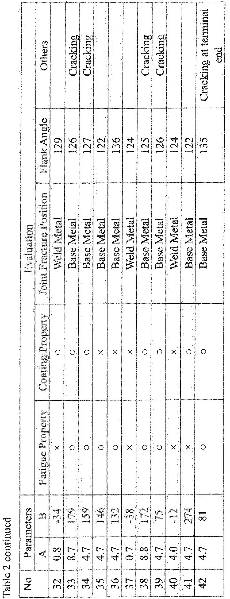
- The wire having the composition shown in Tables 1 and 2, the shielding gas having the composition shown in Tables 1 and 2, and the steel plates having the tensile strength and thickness shown in Tables 1 and 2 were used, and the lap fillet welding according to No. 1 to No. 31 in Table 1 and No. 32 to No. 42 in Table 2 were performed respectively. No. 1 to No. 31 are Examples, and No. 32 to No. 42 are Comparative Examples.
- The extension length of the wire was 15 mm, the width of the lapped portion was 10 mm, and the root gap was 0 mm. The welding speed was 1.0 m/min, the wire diameter was 1.2 mm, the flow rate of the shielding gas was 20 L/min, the torch advancing angle (perpendicular to a welding direction) was absent, and the welding current was 250 A in the case where the thickness was 2.3 mm to 3.6 mm, and was 150 A in the case where the thickness was 1.0 mm to 1.6 mm.
- In Tables 1 and 2, the "wire component (mass%)" represents the content (mass%) of each component contained in the consumable electrode (welding wire). Here, "-" represents that the content is equal to or less than the level of unavoidable impurities. In addition, the remainder was substantially Fe.
- In addition, in Tables 1 and 2, the "mixing ratio (vol.%)" of the shielding gas represents the content of additive components (CO2, O2) in the shielding gas.
In addition, the remainder was Ar and unavoidable impurities. - In addition, the parameters A and B in Tables 1 and 2 are as follows.


- For each example, evaluation was carried out by the following test. These results are shown in Tables 1 and 2.
- Machining was carried out such that weld bead toe on the lower plate side was on the center of the test piece, the test piece was prepared, PBF-30X manufactured by Tokyo Keiki Co., Ltd was used, and a plane bending fatigue test was carried out. The conditions for the plane bending fatigue test were set to 0 for stress ratio and 20 Hz for frequency, and those with a fracture lifetime of 100,000 or more at amplitude stress of 300 MPa were evaluated as "○", and those with less than 100,000 times were evaluated as "×".
- After completion of the welding, it was processed into a test piece, phosphate treatment was carried out such that the phosphate deposit amount was 2.5 g/m2, cation electrodeposition coating was carried out such that a thickness was 30 µm, and coating test body was prepared. After the test body was prepared, a corrosion resistance test was carried out in accordance with SAE J2334, the evaluation of "○" indicates that no red rust was formed in the vicinity of the welded part after completion of 48 cycles, and the evaluation of "×" indicates that red rust was generated.
- After completion of the welding, it was processed into a rectangular test piece with a width of 40 mm, and a static tensile test of the welded joint was carried out. After the tensile test, the fracture position was visually observed and it was distinguished from weld metal fracture, bond fracture, and base metal fracture (including heat affected zone). The bond fracture refers to fraction along the interface between the weld metal and the base metal.
- In addition, the flank angle for the welded structure obtained in each case was measured. The result is shown in Tables 1 and 2.
- In addition, for the cases in which cracking occurred in the welded part, the occurrence of cracking is described in the "Others" column of Tables 1 and 2.


- From the above results, the following can be found.
- In No. 32, the fatigue resistance was inferior since A was less than 1.0.
- In No. 33, cracking occurred at the welded part since A was larger than 8.3.
- In No. 34, cracking occurred at the welded part since the content of C was larger than 0.20%.
- In No. 35, the coating property was inferior since the content of Si was more than 0.50%.
- In No. 36, the coating property was inferior since the content of Mn was more than 0.50%.
- In No. 37, the fatigue resistance and the coating property were inferior since the content of Cr was less than 1.0% and A was less than 1.0.
- In No. 38, cracking occurred at the welded part since the content of Cr was more than 9.0% and A was larger than 8.3.
- In No. 39, cracking occurred at the welded part since the content of S was larger than 0.0600%.
- In No. 40, the fatigue resistance and the coating property were inferior since the content of CO2+O2 in the shielding gas was more than 15%.
- In No. 41, the fatigue resistance was inferior since the tensile strength of the steel plate was less than 780 MPa.
- In No. 42, cracking occurred at the terminal end since the content of Ni was larger than 0.50%.
- On the other hand, since No. 1 to No. 31 satisfy the requirements of the present invention, these were excellent in fatigue resistance and coating property, and occurrence of cracking was not confirmed.
- While the present invention has been described in detail and with reference to specific embodiments thereof, it will be apparent to one skilled in the art that various changes and modifications can be made therein without departing from the spirit and scope thereof.
- This application is based on Japanese Patent Application No.
2016-122702 filed on June 20, 2016 -
- 1
- Welding apparatus
- 10
- Robot
- 11
- Welding torch
- 20
- Robot control portion
- 30
- Welding power supply portion
- 41
- Welded structure
- 42
- Steel plate
- 43
- Welded part
- α
- Flank angle at weld bead toe

Claims (5)
- A gas-shielded arc welding method comprising welding a steel plate having a tensile strength of 780 MPa or more while feeding a consumable electrode via a welding torch and flowing a shielding gas, wherein:the consumable electrode comprises, in mass% based on a total mass of the consumable electrode,C: 0 to 0.20%,Si: 0 to 0.50%,Mn: 0 to 0.50%,Cr: 1.00% to 9.00%,S: 0.0020% to 0.0600%, andNi: 0 to 0.50%;the shielding gas comprises, in vol.%,at least one selected from CO2 and O2: 1% to 15% in total,with the remainder being Ar and unavoidable impurities;welding is performed under the condition satisfying the following relationship (1)

- The gas-shielded arc welding method according to claim 1, wherein welding is performed under the condition satisfying the following relationship (2)

- The gas-shielded arc welding method according to claim 1, wherein the consumable electrode further comprises, in mass% based on the total mass of the consumable electrode,
at least one selected from the group consisting of
Mo: 0.10% or less,
V: 0.10% or less,
Nb: 0.10% or less, and
Cu: 0.50% or less. - The gas-shielded arc welding method according to claim 1, wherein
the steel plate has a thickness of 1.0 mm to 3.6 mm, and
lap fillet welding in which a plurality of the steel plates are lapped and welded is performed. - A method for manufacturing a welded structure, comprising using the gas-shielded arc welding method according to any one of claims 1 to 4,
wherein a flank angle at a weld bead toe of the welded structure is 130° to 150°.
Applications Claiming Priority (2)
| Application Number | Priority Date | Filing Date | Title |
|---|---|---|---|
| JP2016122072A JP6594266B2 (en) | 2016-06-20 | 2016-06-20 | Gas shield arc welding method and manufacturing method of welded structure |
| PCT/JP2017/022456 WO2017221865A1 (en) | 2016-06-20 | 2017-06-19 | Gas-shielded arc welding method and method for manufacturing welded structure |
Publications (3)
| Publication Number | Publication Date |
|---|---|
| EP3473368A1 true EP3473368A1 (en) | 2019-04-24 |
| EP3473368A4 EP3473368A4 (en) | 2019-12-18 |
| EP3473368B1 EP3473368B1 (en) | 2021-03-31 |
Family
ID=60784582
Family Applications (1)
| Application Number | Title | Priority Date | Filing Date |
|---|---|---|---|
| EP17815333.4A Active EP3473368B1 (en) | 2016-06-20 | 2017-06-19 | Gas-shielded arc welding method and method for manufacturing welded structure |
Country Status (6)
| Country | Link |
|---|---|
| US (1) | US12134153B2 (en) |
| EP (1) | EP3473368B1 (en) |
| JP (1) | JP6594266B2 (en) |
| KR (1) | KR102121188B1 (en) |
| CN (1) | CN109311114B (en) |
| WO (1) | WO2017221865A1 (en) |
Cited By (1)
| Publication number | Priority date | Publication date | Assignee | Title |
|---|---|---|---|---|
| EP4306254A4 (en) * | 2021-04-28 | 2025-01-15 | JFE Steel Corporation | ARC WELDED JOINT AND ARC WELDING PROCESS |
Families Citing this family (9)
| Publication number | Priority date | Publication date | Assignee | Title |
|---|---|---|---|---|
| JP6619300B2 (en) * | 2016-07-27 | 2019-12-11 | 株式会社神戸製鋼所 | Welding equipment |
| WO2019245063A1 (en) * | 2018-06-18 | 2019-12-26 | 주식회사 포스코 | Plated steel sheet weld member having excellent porosity-resistance and fatigue property of weld zone, and method for manufacturing same |
| US11815127B2 (en) | 2016-12-23 | 2023-11-14 | Posco Co., Ltd | Welded member for plated steel plate excellent in weld zone porosity resistance and fatigue properties and method for manufacturing the same |
| CN113677817B (en) * | 2019-03-27 | 2022-12-09 | 日本制铁株式会社 | Automobile traveling part |
| JP7564227B2 (en) * | 2020-04-28 | 2024-10-08 | ポスコホールディングス インコーポレーティッド | Welding wire capable of producing giga-class welds, welded structure manufactured using the same, and welding method thereof |
| KR102428825B1 (en) * | 2020-12-18 | 2022-08-02 | 주식회사 포스코 | Welded member having excellent fatigue strength of weld zone and method of manufacturing the same |
| CN116833522A (en) * | 2022-03-24 | 2023-10-03 | 本田技研工业株式会社 | Welded body and method for manufacturing welded body |
| WO2024204428A1 (en) * | 2023-03-31 | 2024-10-03 | Jfeスチール株式会社 | Method for manufacturing welded joint through gas-shielded arc welding of steel plate |
| WO2024204429A1 (en) * | 2023-03-31 | 2024-10-03 | Jfeスチール株式会社 | Production method for welded joint by gas-shielded arc welding of steel plate |
Family Cites Families (30)
| Publication number | Priority date | Publication date | Assignee | Title |
|---|---|---|---|---|
| JPS60111779A (en) * | 1983-11-21 | 1985-06-18 | Kawasaki Steel Corp | Gas shielded arc welding method by which deposited metal having excellent resistance to sr embrittleness |
| JPH07276086A (en) * | 1993-09-07 | 1995-10-24 | Nippon Steel Corp | MAG welding flux-cored wire with little welding deformation |
| JPH08290290A (en) * | 1995-04-20 | 1996-11-05 | Mitsubishi Heavy Ind Ltd | High toughness welding material for high-chrome steel |
| JP3283769B2 (en) * | 1996-10-29 | 2002-05-20 | 株式会社神戸製鋼所 | Gas shielded arc weld metal of high strength Cr-Mo steel and gas shielded arc welding method |
| US6428633B1 (en) * | 1997-10-20 | 2002-08-06 | Nippin Steel Corporation | Steel for welded structures and welding wire |
| JP2000312987A (en) * | 1999-04-28 | 2000-11-14 | Sumitomo Metal Ind Ltd | Welding wire |
| US6784401B2 (en) * | 2001-01-30 | 2004-08-31 | Illinois Tool Works Inc. | Welding electrode and method for reducing manganese in fume |
| JP3860437B2 (en) | 2001-03-29 | 2006-12-20 | 株式会社神戸製鋼所 | Iron-based consumable welding materials and welded joints with excellent fatigue strength at welded joints |
| KR100427546B1 (en) * | 2001-09-06 | 2004-04-30 | 고려용접봉 주식회사 | Basic flux cored wire |
| JP3758040B2 (en) * | 2002-07-26 | 2006-03-22 | 株式会社神戸製鋼所 | Flux-cored wire for gas shielded arc welding for low alloy heat resistant steel |
| JP3892782B2 (en) * | 2002-08-30 | 2007-03-14 | 新日本製鐵株式会社 | Gas shielded arc welding wire for low alloy steel excellent in hydrochloric acid resistance and sulfuric acid resistance and gas shielded arc welding method using the same |
| US7863538B2 (en) * | 2004-03-19 | 2011-01-04 | Hobart Brothers Company | Metal-core gas metal arc welding of ferrous steels with noble gas shielding |
| CN1257790C (en) * | 2005-02-03 | 2006-05-31 | 天津大学 | Solid welding wire for lifting welding joint fatigne performance |
| JP4603399B2 (en) | 2005-03-29 | 2010-12-22 | 新日本製鐵株式会社 | Metal-based flux-cored wire and welding method |
| US8269144B2 (en) * | 2006-02-21 | 2012-09-18 | Lincoln Global, Inc. | High strength stick electrode |
| JP5019781B2 (en) | 2006-04-27 | 2012-09-05 | 株式会社神戸製鋼所 | MIG arc welding method using gas shielded arc welding flux cored wire |
| JP5163215B2 (en) | 2008-03-25 | 2013-03-13 | 新日鐵住金株式会社 | Fillet arc welding method for thin steel sheet |
| JP5205115B2 (en) * | 2008-04-16 | 2013-06-05 | 株式会社神戸製鋼所 | MIG flux-cored wire for pure Ar shield gas welding and MIG arc welding method |
| CN102046325B (en) * | 2008-05-27 | 2014-04-23 | 新日铁住金不锈钢株式会社 | Flux-cored wire for welding of duplex stainless steel which enables the miniaturization of solidified crystal particles |
| MX2012003512A (en) | 2009-09-25 | 2012-05-08 | Nippon Steel Corp | Method for fillet arc welding high-strength thin steel sheets. |
| JP5198481B2 (en) * | 2010-01-09 | 2013-05-15 | 株式会社神戸製鋼所 | Ni-based alloy flux cored wire |
| US9259806B2 (en) * | 2012-05-08 | 2016-02-16 | Nippon Steel & Sumitomo Metal Corporation | Flux-cored wire for welding ultrahigh tensile strength steel |
| CN104981319B (en) * | 2013-02-15 | 2018-04-24 | 新日铁住金株式会社 | Gas protective arc welding solid welding wire, gas protective arc welding metal, welding point, welding assembly, the manufacture method of welding method and welding point |
| JP6265051B2 (en) | 2013-05-31 | 2018-01-24 | 新日鐵住金株式会社 | Flux-cored wire with excellent fatigue strength and cold cracking resistance of welded joints |
| JP6257193B2 (en) * | 2013-07-12 | 2018-01-10 | 株式会社神戸製鋼所 | Flux-cored wire for overlay welding |
| JP6040125B2 (en) * | 2013-08-30 | 2016-12-07 | 株式会社神戸製鋼所 | Flux cored wire |
| EP3055101A2 (en) * | 2013-10-09 | 2016-08-17 | Hobart Brothers Company | Systems and methods for corrosion-resistant welding electrodes |
| KR101674743B1 (en) * | 2013-11-08 | 2016-11-09 | 신닛테츠스미킨 카부시키카이샤 | Flux-cored wire for gas-shielded arc welding, method for welding steel for very low temperature use, and method for manufacturing weld joint |
| SG11201702429UA (en) * | 2014-10-15 | 2017-04-27 | Kobe Steel Ltd | Wire containing flux for gas shield arc welding |
| CN104668820B (en) * | 2015-02-12 | 2017-01-04 | 江苏省沙钢钢铁研究院有限公司 | A kind of production method of heat-resistant steel welding wire |
-
2016
- 2016-06-20 JP JP2016122072A patent/JP6594266B2/en active Active
-
2017
- 2017-06-19 US US16/311,268 patent/US12134153B2/en active Active
- 2017-06-19 CN CN201780037924.0A patent/CN109311114B/en active Active
- 2017-06-19 WO PCT/JP2017/022456 patent/WO2017221865A1/en not_active Ceased
- 2017-06-19 EP EP17815333.4A patent/EP3473368B1/en active Active
- 2017-06-19 KR KR1020187036556A patent/KR102121188B1/en active Active
Cited By (1)
| Publication number | Priority date | Publication date | Assignee | Title |
|---|---|---|---|---|
| EP4306254A4 (en) * | 2021-04-28 | 2025-01-15 | JFE Steel Corporation | ARC WELDED JOINT AND ARC WELDING PROCESS |
Also Published As
| Publication number | Publication date |
|---|---|
| US20190232417A1 (en) | 2019-08-01 |
| CN109311114B (en) | 2021-10-12 |
| EP3473368A4 (en) | 2019-12-18 |
| JP2017225986A (en) | 2017-12-28 |
| KR102121188B1 (en) | 2020-06-10 |
| US12134153B2 (en) | 2024-11-05 |
| WO2017221865A1 (en) | 2017-12-28 |
| JP6594266B2 (en) | 2019-10-23 |
| CN109311114A (en) | 2019-02-05 |
| EP3473368B1 (en) | 2021-03-31 |
| KR20190005231A (en) | 2019-01-15 |
Similar Documents
| Publication | Publication Date | Title |
|---|---|---|
| EP3473368B1 (en) | Gas-shielded arc welding method and method for manufacturing welded structure | |
| JP6829699B2 (en) | Ultra-low silicon welding wire with excellent pore resistance and electrodeposition coating, and the weld metal obtained by this wire. | |
| EP2402103B1 (en) | Fillet weld joint and method for gas shielded arc welding | |
| KR100876496B1 (en) | Gas shielded arc welding solid wire for weathering steel and gas shielded arc welding method using the same | |
| JP6432716B1 (en) | Fillet welded joint and manufacturing method thereof | |
| EP3228413B1 (en) | Method for producing circumferential weld joint for low-carbon martensite stainless steel tubing | |
| CA3079810A1 (en) | Solid wire for gas-shielded arc welding of thin steel sheet | |
| EP2380696A1 (en) | Stainless steel flux-cored welding wire for the welding of galvanized steel sheets and process for arc welding of galvanized steel sheets with the same | |
| WO2018203513A1 (en) | Arc welding method and welding wire | |
| JP4857015B2 (en) | Gas shielded arc welding flux cored wire and welding method | |
| CN113001057B (en) | High-strength pitting-resistant nitrogen-containing austenitic stainless steel flux-cored wire and preparation method thereof | |
| JP2012081514A (en) | Fillet arc welding method of galvanized steel sheet | |
| JP3576472B2 (en) | Welding material for low carbon martensitic stainless steel and arc welding method for low carbon martensitic stainless steel | |
| JP6829111B2 (en) | Filling material for TIG welding | |
| JP3815227B2 (en) | Martensitic stainless steel welded joint with excellent strain aging resistance | |
| EP3208031A1 (en) | Wire containing flux for gas shield arc welding | |
| CN107614724A (en) | Steel plate and welding point | |
| KR100805060B1 (en) | Teak welding method for improved pitting corrosion resistance of 22% Cr-based two-phase stainless steel | |
| JP7619819B2 (en) | Flux-cored wire, weld metal, gas-shielded arc welding method, and method for manufacturing welded joint | |
| JP4427350B2 (en) | Weld metal with excellent strength uniformity | |
| JPS5961590A (en) | Welding method | |
| EP4545244A1 (en) | Gas shield arc welding wire | |
| KR100581027B1 (en) | Flux Filling Wire for Martensitic Stainless Steel Welding | |
| EP4653119A1 (en) | Projection weld joint and method for manufacturing same | |
| EP4316727A1 (en) | Filler metal for welding of dissimilar welds |
Legal Events
| Date | Code | Title | Description |
|---|---|---|---|
| STAA | Information on the status of an ep patent application or granted ep patent |
Free format text: STATUS: THE INTERNATIONAL PUBLICATION HAS BEEN MADE |
|
| PUAI | Public reference made under article 153(3) epc to a published international application that has entered the european phase |
Free format text: ORIGINAL CODE: 0009012 |
|
| STAA | Information on the status of an ep patent application or granted ep patent |
Free format text: STATUS: REQUEST FOR EXAMINATION WAS MADE |
|
| 17P | Request for examination filed |
Effective date: 20181220 |
|
| AK | Designated contracting states |
Kind code of ref document: A1 Designated state(s): AL AT BE BG CH CY CZ DE DK EE ES FI FR GB GR HR HU IE IS IT LI LT LU LV MC MK MT NL NO PL PT RO RS SE SI SK SM TR |
|
| AX | Request for extension of the european patent |
Extension state: BA ME |
|
| DAV | Request for validation of the european patent (deleted) | ||
| DAX | Request for extension of the european patent (deleted) | ||
| A4 | Supplementary search report drawn up and despatched |
Effective date: 20191118 |
|
| RIC1 | Information provided on ipc code assigned before grant |
Ipc: B23K 9/173 20060101AFI20191112BHEP Ipc: B23K 35/38 20060101ALI20191112BHEP Ipc: B23K 35/30 20060101ALI20191112BHEP Ipc: C22C 38/00 20060101ALI20191112BHEP Ipc: B23K 35/32 20060101ALI20191112BHEP Ipc: B23K 9/23 20060101ALI20191112BHEP |
|
| RIC1 | Information provided on ipc code assigned before grant |
Ipc: B23K 9/173 20060101AFI20200831BHEP Ipc: B23K 35/32 20060101ALI20200831BHEP Ipc: B23K 9/23 20060101ALI20200831BHEP Ipc: B23K 35/30 20060101ALI20200831BHEP Ipc: C22C 38/00 20060101ALI20200831BHEP Ipc: B23K 35/38 20060101ALI20200831BHEP |
|
| GRAP | Despatch of communication of intention to grant a patent |
Free format text: ORIGINAL CODE: EPIDOSNIGR1 |
|
| STAA | Information on the status of an ep patent application or granted ep patent |
Free format text: STATUS: GRANT OF PATENT IS INTENDED |
|
| INTG | Intention to grant announced |
Effective date: 20201021 |
|
| GRAS | Grant fee paid |
Free format text: ORIGINAL CODE: EPIDOSNIGR3 |
|
| GRAA | (expected) grant |
Free format text: ORIGINAL CODE: 0009210 |
|
| STAA | Information on the status of an ep patent application or granted ep patent |
Free format text: STATUS: THE PATENT HAS BEEN GRANTED |
|
| AK | Designated contracting states |
Kind code of ref document: B1 Designated state(s): AL AT BE BG CH CY CZ DE DK EE ES FI FR GB GR HR HU IE IS IT LI LT LU LV MC MK MT NL NO PL PT RO RS SE SI SK SM TR |
|
| REG | Reference to a national code |
Ref country code: GB Ref legal event code: FG4D Ref country code: CH Ref legal event code: EP |
|
| REG | Reference to a national code |
Ref country code: AT Ref legal event code: REF Ref document number: 1376392 Country of ref document: AT Kind code of ref document: T Effective date: 20210415 |
|
| REG | Reference to a national code |
Ref country code: DE Ref legal event code: R096 Ref document number: 602017035875 Country of ref document: DE |
|
| REG | Reference to a national code |
Ref country code: IE Ref legal event code: FG4D |
|
| REG | Reference to a national code |
Ref country code: LT Ref legal event code: MG9D |
|
| PG25 | Lapsed in a contracting state [announced via postgrant information from national office to epo] |
Ref country code: BG Free format text: LAPSE BECAUSE OF FAILURE TO SUBMIT A TRANSLATION OF THE DESCRIPTION OR TO PAY THE FEE WITHIN THE PRESCRIBED TIME-LIMIT Effective date: 20210630 Ref country code: NO Free format text: LAPSE BECAUSE OF FAILURE TO SUBMIT A TRANSLATION OF THE DESCRIPTION OR TO PAY THE FEE WITHIN THE PRESCRIBED TIME-LIMIT Effective date: 20210630 Ref country code: HR Free format text: LAPSE BECAUSE OF FAILURE TO SUBMIT A TRANSLATION OF THE DESCRIPTION OR TO PAY THE FEE WITHIN THE PRESCRIBED TIME-LIMIT Effective date: 20210331 Ref country code: FI Free format text: LAPSE BECAUSE OF FAILURE TO SUBMIT A TRANSLATION OF THE DESCRIPTION OR TO PAY THE FEE WITHIN THE PRESCRIBED TIME-LIMIT Effective date: 20210331 |
|
| PG25 | Lapsed in a contracting state [announced via postgrant information from national office to epo] |
Ref country code: LV Free format text: LAPSE BECAUSE OF FAILURE TO SUBMIT A TRANSLATION OF THE DESCRIPTION OR TO PAY THE FEE WITHIN THE PRESCRIBED TIME-LIMIT Effective date: 20210331 Ref country code: RS Free format text: LAPSE BECAUSE OF FAILURE TO SUBMIT A TRANSLATION OF THE DESCRIPTION OR TO PAY THE FEE WITHIN THE PRESCRIBED TIME-LIMIT Effective date: 20210331 Ref country code: SE Free format text: LAPSE BECAUSE OF FAILURE TO SUBMIT A TRANSLATION OF THE DESCRIPTION OR TO PAY THE FEE WITHIN THE PRESCRIBED TIME-LIMIT Effective date: 20210331 |
|
| REG | Reference to a national code |
Ref country code: NL Ref legal event code: MP Effective date: 20210331 |
|
| REG | Reference to a national code |
Ref country code: AT Ref legal event code: MK05 Ref document number: 1376392 Country of ref document: AT Kind code of ref document: T Effective date: 20210331 |
|
| PG25 | Lapsed in a contracting state [announced via postgrant information from national office to epo] |
Ref country code: SM Free format text: LAPSE BECAUSE OF FAILURE TO SUBMIT A TRANSLATION OF THE DESCRIPTION OR TO PAY THE FEE WITHIN THE PRESCRIBED TIME-LIMIT Effective date: 20210331 Ref country code: NL Free format text: LAPSE BECAUSE OF FAILURE TO SUBMIT A TRANSLATION OF THE DESCRIPTION OR TO PAY THE FEE WITHIN THE PRESCRIBED TIME-LIMIT Effective date: 20210331 Ref country code: AT Free format text: LAPSE BECAUSE OF FAILURE TO SUBMIT A TRANSLATION OF THE DESCRIPTION OR TO PAY THE FEE WITHIN THE PRESCRIBED TIME-LIMIT Effective date: 20210331 Ref country code: CZ Free format text: LAPSE BECAUSE OF FAILURE TO SUBMIT A TRANSLATION OF THE DESCRIPTION OR TO PAY THE FEE WITHIN THE PRESCRIBED TIME-LIMIT Effective date: 20210331 Ref country code: EE Free format text: LAPSE BECAUSE OF FAILURE TO SUBMIT A TRANSLATION OF THE DESCRIPTION OR TO PAY THE FEE WITHIN THE PRESCRIBED TIME-LIMIT Effective date: 20210331 Ref country code: LT Free format text: LAPSE BECAUSE OF FAILURE TO SUBMIT A TRANSLATION OF THE DESCRIPTION OR TO PAY THE FEE WITHIN THE PRESCRIBED TIME-LIMIT Effective date: 20210331 |
|
| PG25 | Lapsed in a contracting state [announced via postgrant information from national office to epo] |
Ref country code: IS Free format text: LAPSE BECAUSE OF FAILURE TO SUBMIT A TRANSLATION OF THE DESCRIPTION OR TO PAY THE FEE WITHIN THE PRESCRIBED TIME-LIMIT Effective date: 20210731 Ref country code: PT Free format text: LAPSE BECAUSE OF FAILURE TO SUBMIT A TRANSLATION OF THE DESCRIPTION OR TO PAY THE FEE WITHIN THE PRESCRIBED TIME-LIMIT Effective date: 20210802 Ref country code: PL Free format text: LAPSE BECAUSE OF FAILURE TO SUBMIT A TRANSLATION OF THE DESCRIPTION OR TO PAY THE FEE WITHIN THE PRESCRIBED TIME-LIMIT Effective date: 20210331 Ref country code: SK Free format text: LAPSE BECAUSE OF FAILURE TO SUBMIT A TRANSLATION OF THE DESCRIPTION OR TO PAY THE FEE WITHIN THE PRESCRIBED TIME-LIMIT Effective date: 20210331 Ref country code: RO Free format text: LAPSE BECAUSE OF FAILURE TO SUBMIT A TRANSLATION OF THE DESCRIPTION OR TO PAY THE FEE WITHIN THE PRESCRIBED TIME-LIMIT Effective date: 20210331 |
|
| REG | Reference to a national code |
Ref country code: DE Ref legal event code: R097 Ref document number: 602017035875 Country of ref document: DE |
|
| PG25 | Lapsed in a contracting state [announced via postgrant information from national office to epo] |
Ref country code: MC Free format text: LAPSE BECAUSE OF FAILURE TO SUBMIT A TRANSLATION OF THE DESCRIPTION OR TO PAY THE FEE WITHIN THE PRESCRIBED TIME-LIMIT Effective date: 20210331 Ref country code: AL Free format text: LAPSE BECAUSE OF FAILURE TO SUBMIT A TRANSLATION OF THE DESCRIPTION OR TO PAY THE FEE WITHIN THE PRESCRIBED TIME-LIMIT Effective date: 20210331 Ref country code: DK Free format text: LAPSE BECAUSE OF FAILURE TO SUBMIT A TRANSLATION OF THE DESCRIPTION OR TO PAY THE FEE WITHIN THE PRESCRIBED TIME-LIMIT Effective date: 20210331 Ref country code: ES Free format text: LAPSE BECAUSE OF FAILURE TO SUBMIT A TRANSLATION OF THE DESCRIPTION OR TO PAY THE FEE WITHIN THE PRESCRIBED TIME-LIMIT Effective date: 20210331 |
|
| REG | Reference to a national code |
Ref country code: CH Ref legal event code: PL |
|
| PLBE | No opposition filed within time limit |
Free format text: ORIGINAL CODE: 0009261 |
|
| STAA | Information on the status of an ep patent application or granted ep patent |
Free format text: STATUS: NO OPPOSITION FILED WITHIN TIME LIMIT |
|
| GBPC | Gb: european patent ceased through non-payment of renewal fee |
Effective date: 20210630 |
|
| 26N | No opposition filed |
Effective date: 20220104 |
|
| REG | Reference to a national code |
Ref country code: BE Ref legal event code: MM Effective date: 20210630 |
|
| PG25 | Lapsed in a contracting state [announced via postgrant information from national office to epo] |
Ref country code: LU Free format text: LAPSE BECAUSE OF NON-PAYMENT OF DUE FEES Effective date: 20210619 |
|
| PG25 | Lapsed in a contracting state [announced via postgrant information from national office to epo] |
Ref country code: LI Free format text: LAPSE BECAUSE OF NON-PAYMENT OF DUE FEES Effective date: 20210630 Ref country code: IE Free format text: LAPSE BECAUSE OF NON-PAYMENT OF DUE FEES Effective date: 20210619 Ref country code: GB Free format text: LAPSE BECAUSE OF NON-PAYMENT OF DUE FEES Effective date: 20210630 Ref country code: CH Free format text: LAPSE BECAUSE OF NON-PAYMENT OF DUE FEES Effective date: 20210630 |
|
| PG25 | Lapsed in a contracting state [announced via postgrant information from national office to epo] |
Ref country code: IS Free format text: LAPSE BECAUSE OF FAILURE TO SUBMIT A TRANSLATION OF THE DESCRIPTION OR TO PAY THE FEE WITHIN THE PRESCRIBED TIME-LIMIT Effective date: 20210731 Ref country code: FR Free format text: LAPSE BECAUSE OF NON-PAYMENT OF DUE FEES Effective date: 20210630 |
|
| PG25 | Lapsed in a contracting state [announced via postgrant information from national office to epo] |
Ref country code: IT Free format text: LAPSE BECAUSE OF FAILURE TO SUBMIT A TRANSLATION OF THE DESCRIPTION OR TO PAY THE FEE WITHIN THE PRESCRIBED TIME-LIMIT Effective date: 20210331 Ref country code: BE Free format text: LAPSE BECAUSE OF NON-PAYMENT OF DUE FEES Effective date: 20210630 |
|
| P01 | Opt-out of the competence of the unified patent court (upc) registered |
Effective date: 20230520 |
|
| PG25 | Lapsed in a contracting state [announced via postgrant information from national office to epo] |
Ref country code: CY Free format text: LAPSE BECAUSE OF FAILURE TO SUBMIT A TRANSLATION OF THE DESCRIPTION OR TO PAY THE FEE WITHIN THE PRESCRIBED TIME-LIMIT Effective date: 20210331 |
|
| PG25 | Lapsed in a contracting state [announced via postgrant information from national office to epo] |
Ref country code: HU Free format text: LAPSE BECAUSE OF FAILURE TO SUBMIT A TRANSLATION OF THE DESCRIPTION OR TO PAY THE FEE WITHIN THE PRESCRIBED TIME-LIMIT; INVALID AB INITIO Effective date: 20170619 Ref country code: GR Free format text: LAPSE BECAUSE OF FAILURE TO SUBMIT A TRANSLATION OF THE DESCRIPTION OR TO PAY THE FEE WITHIN THE PRESCRIBED TIME-LIMIT Effective date: 20210331 |
|
| PG25 | Lapsed in a contracting state [announced via postgrant information from national office to epo] |
Ref country code: MK Free format text: LAPSE BECAUSE OF FAILURE TO SUBMIT A TRANSLATION OF THE DESCRIPTION OR TO PAY THE FEE WITHIN THE PRESCRIBED TIME-LIMIT Effective date: 20210331 |
|
| PG25 | Lapsed in a contracting state [announced via postgrant information from national office to epo] |
Ref country code: TR Free format text: LAPSE BECAUSE OF FAILURE TO SUBMIT A TRANSLATION OF THE DESCRIPTION OR TO PAY THE FEE WITHIN THE PRESCRIBED TIME-LIMIT Effective date: 20210331 |
|
| PG25 | Lapsed in a contracting state [announced via postgrant information from national office to epo] |
Ref country code: MT Free format text: LAPSE BECAUSE OF FAILURE TO SUBMIT A TRANSLATION OF THE DESCRIPTION OR TO PAY THE FEE WITHIN THE PRESCRIBED TIME-LIMIT Effective date: 20210331 |
|
| PGFP | Annual fee paid to national office [announced via postgrant information from national office to epo] |
Ref country code: DE Payment date: 20250429 Year of fee payment: 9 |