JP6829111B2 - Filling material for TIG welding - Google Patents
Filling material for TIG welding Download PDFInfo
- Publication number
- JP6829111B2 JP6829111B2 JP2017039844A JP2017039844A JP6829111B2 JP 6829111 B2 JP6829111 B2 JP 6829111B2 JP 2017039844 A JP2017039844 A JP 2017039844A JP 2017039844 A JP2017039844 A JP 2017039844A JP 6829111 B2 JP6829111 B2 JP 6829111B2
- Authority
- JP
- Japan
- Prior art keywords
- mass
- less
- content
- welding
- present
- Prior art date
- Legal status (The legal status is an assumption and is not a legal conclusion. Google has not performed a legal analysis and makes no representation as to the accuracy of the status listed.)
- Active
Links
Images


Landscapes
- Arc Welding In General (AREA)
Description
本発明は、TIG(Tungsten Inert Gas)溶接用溶加材に関する。より詳細には、特に、400N/mm2級の引張強度を有する低強度鋼用のTIG溶接材料として有用な、TIG溶接用溶加材に関する。 The present invention relates to a filler material for TIG (Tungsten Inert Gas) welding. More specifically, the present invention relates to a filler material for TIG welding, which is useful as a TIG welding material for low-strength steel having a tensile strength of 400 N / mm class 2 .
従来、溶接構造用圧延鋼として種々の鋼材が用いられており、例えば、溶接構造用圧延鋼SM400(JIS G3106)に代表される400MPa級の引張強度を有する鋼材(400MPa級鋼)が用いられている。構造物を溶接する場合、一般的には、当該構造物に荷重が印加された際に、溶接部ではなく母材の部分で破壊が生じるように設計される。したがって、一般的には、溶接部には母材よりも高い強度が要求される。ここで、JIS Z3316には、軟鋼、高張力鋼及び低温用鋼用TIG溶接溶加棒及びソリッドワイヤの規格が定められている。 Conventionally, various steel materials have been used as rolled steel for welded structures. For example, a steel material (400 MPa class steel) having a tensile strength of 400 MPa class represented by rolled steel for welded structure SM400 (JIS G3106) has been used. There is. When a structure is welded, it is generally designed so that when a load is applied to the structure, the base metal portion is broken instead of the welded portion. Therefore, in general, the welded portion is required to have higher strength than the base metal. Here, JIS Z3316 defines standards for TIG welding filler rods and solid wires for mild steel, high-strength steel, and low-temperature steel.
ここで、炭素鋼のTIG溶接においては、一般的に、シールドガスとして高純度のアルゴン(Ar)ガスが用いられる。アルゴンガスは溶融池の酸化反応を生じさせないので、溶接金属の酸素量は他の溶接法と比べて著しく低くなる。したがって、TIG溶接金属は、酸化物等の介在物が少なく、強度や靱性に優れるという性質を有する。 Here, in TIG welding of carbon steel, high-purity argon (Ar) gas is generally used as the shield gas. Since the argon gas does not cause an oxidation reaction in the molten pool, the oxygen content of the weld metal is significantly lower than that of other welding methods. Therefore, the TIG weld metal has the property of having few inclusions such as oxides and being excellent in strength and toughness.
しかしながら、酸素量の少ない炭素鋼は焼入れ性が非常に高くなるという性質を有するため、溶接金属の原質部では強度及び硬度が非常に上昇するといった問題があった。特に、厚板の場合には、薄板の場合と比較して冷却速度が速くなり、焼入れ性がさらに高められる結果、過剰硬度が助長されるという問題があった。
また、多層溶接における最終層や単層溶接など、溶接による再熱を受けない箇所では、組織が原質部となるため、硬度が過剰に高くなる場合があり、遅れ割れや硫化物応力腐食割れ(SSCC)が発生する恐れがあった。これら割れは、溶接金属の拡散性水素量や溶接金属へ負荷される拘束力にも依存するが、一般的に溶接金属のビッカース硬さがHV350以上となった場合、割れが発生しやすいとされている。
However, since carbon steel having a small amount of oxygen has a property of having a very high hardenability, there is a problem that the strength and hardness of the raw material portion of the weld metal are greatly increased. In particular, in the case of a thick plate, the cooling rate is faster than in the case of a thin plate, and as a result of further enhancing the hardenability, there is a problem that excess hardness is promoted.
In addition, in places that are not reheated by welding, such as the final layer in multi-layer welding and single-layer welding, the structure becomes the raw material, so the hardness may become excessively high, resulting in delayed cracking and sulfide stress corrosion cracking. (SSCC) may occur. These cracks depend on the amount of diffusible hydrogen in the weld metal and the binding force applied to the weld metal, but it is generally said that cracks are likely to occur when the Vickers hardness of the weld metal is HV350 or higher. ing.
ここで、溶接材料の硬度を低減させる方法としては、溶接施工面において、冷却速度を小さくするために溶接入熱を増加させ、予熱温度及びパス間温度を上昇させる方法が知られている。また、溶接後熱処理(PWHT)として、硬化した原質部を焼鈍することによって組織を焼戻し、硬度を低下させる方法も知られている。 Here, as a method for reducing the hardness of the welding material, a method is known in which the welding heat input is increased in order to reduce the cooling rate, and the preheating temperature and the interpass temperature are increased on the welding surface. Further, as a post-weld heat treatment (PWHT), a method is also known in which the structure is tempered by annealing the cured raw material portion to reduce the hardness.
しかしながら、これらの方法では工数が増加するため、生産性が低下し、コストが上昇するといった問題があった。また、溶接入熱の増加は熱影響部(HAZ)に影響し、継手強度を確保できなくなるといった問題もあった。さらに、溶接後熱処理(PWHT)についても、炉の大きさや溶接構造物の大きさによっては、熱処理を適用することが難しいという設備上の制約もあった。 However, these methods have a problem that the man-hours increase, so that the productivity decreases and the cost increases. Further, the increase in welding heat input affects the heat-affected zone (HAZ), and there is also a problem that the joint strength cannot be secured. Further, regarding the post-weld heat treatment (PWHT), there is also an equipment restriction that it is difficult to apply the heat treatment depending on the size of the furnace and the size of the welded structure.
また、溶接材料として、例えば、特許文献1には、Cが0.03重量%以下、Siが0.05重量%以下、Mnが0.80重量%以下、Tiが0.008重量%以下、Oが0.025重量%以下に規制され残部がFe及び不可避的不純物からなることを特徴とするガスシールドアーク溶接用ソリッドワイヤが記載されている。
Further, as welding materials, for example,
特許文献1に記載のガスシールドアーク溶接用ソリッドワイヤは、単層溶接における溶接金属の過剰硬度を抑制するためには有効である。しかしながら、多層溶接のような再熱部を含む溶接金属の強度は、鋼板強度よりも軟化するため、特許文献1に記載のガスシールドアーク溶接用ソリッドワイヤは、400MPa級鋼用の溶接材料として求められる溶接継手強度を満足することができないという問題があった。すなわち、特許文献1に記載のガスシールドアーク溶接用ソリッドワイヤを用いた溶接金属は、いずれも引張強度が400MPaよりも低いものであった。また、多層溶接で硬度過剰となる最終層のみを当該ワイヤで施行することで原質部の硬度を低下させることも考えられるが、ワイヤ管理面や溶接施工の効率面における問題があった。
The solid wire for gas shielded arc welding described in
前記従来の課題を鑑みて、本発明は、単層溶接における遅れ割れの要因となる溶接金属の過剰硬度を抑制するとともに、多層溶接において400MPa級鋼の溶接材料として求められる溶接継手性能(強度、靱性等)を満足するTIG溶接用溶加材を提供することを目的とする。 In view of the above-mentioned conventional problems, the present invention suppresses excess hardness of the weld metal that causes delayed cracking in single-layer welding, and weld joint performance (strength,) required as a welding material for 400 MPa class steel in multi-layer welding. It is an object of the present invention to provide a filler metal for TIG welding that satisfies (toughness, etc.).
前記目的を達成するために、本発明は、C:0.02〜0.06質量%、Si:0.30〜0.85質量%、及びMn:0.70〜1.40質量%を含有し、Ni:0.10質量%以下(但し、0質量%を含む)、Cr:0.10質量%以下(但し、0質量%を含む)、Mo:0.10質量%以下(但し、0質量%を含む)、V:0.05質量%以下(但し、0質量%を含む)、P:0.030質量%以下(但し、0質量%を含まない)、S:0.030質量%以下(但し、0質量%を含まない)、及びN:0.0100質量%以下(但し、0質量%を含まない)にそれぞれ規制され、残部がFeおよび不可避的不純物からなり、かつ、下記式(1)で表される炭素当量Ceqが0.15〜0.35の範囲内であるTIG溶接用溶加材を提供する。
Ceq=[C]+[Si]/24+[Mn]/6+[Ni]/40+[Cr]/5+[Mo]/4+[V]/14 (1)
(但し、[C]、[Si]、[Mn]、[Ni]、[Cr]、[Mo]および[V]は、それぞれC、Si、Mn、Ni、Cr、MoおよびVの含有量(質量%)を示す。)
In order to achieve the above object, the present invention contains C: 0.02 to 0.06% by mass, Si: 0.30 to 0.85% by mass, and Mn: 0.70 to 1.40% by mass. However, Ni: 0.10% by mass or less (however, including 0% by mass), Cr: 0.10% by mass or less (however, including 0% by mass), Mo: 0.10% by mass or less (however, 0% by mass) (Including mass%), V: 0.05% by mass or less (however, including 0% by mass), P: 0.030% by mass or less (however, not including 0% by mass), S: 0.030% by mass It is regulated to the following (however, 0% by mass is not included) and N: 0.0100% by mass or less (however, 0% by mass is not included), and the balance consists of Fe and unavoidable impurities, and the following formula Provided is a filler material for TIG welding in which the carbon equivalent Ceq represented by (1) is in the range of 0.15 to 0.35.
Ceq = [C] + [Si] / 24 + [Mn] / 6 + [Ni] / 40 + [Cr] / 5 + [Mo] / 4 + [V] / 14 (1)
(However, [C], [Si], [Mn], [Ni], [Cr], [Mo] and [V] are the contents of C, Si, Mn, Ni, Cr, Mo and V, respectively. Mass%) is shown.)
ここで、本発明のTIG溶接用溶加材においては、前記炭素当量Ceqが0.20〜0.33の範囲内であってもよい。 Here, in the filler metal for TIG welding of the present invention, the carbon equivalent Ceq may be in the range of 0.20 to 0.33.
また、本発明のTIG溶接用溶加材は、Al:0.10質量%以下(但し、0質量%を含む)、Ti:0.10質量%以下(但し、0質量%を含む)、Zr:0.10質量%以下(但し、0質量%を含む)、及びO:0.0100質量%以下(但し、0質量%を含まない)からなる群から選ばれる少なくとも1種をさらに含有し、かつ下記式(2)の関係を満足するものであってもよい。
[X]=([Ti]+[Al]+[Zr])×[O]×10000≦10.0 (2)
(但し、[Ti]、[Al]、[Zr]、および[O]は、それぞれTi、Al、ZrおよびOの含有量(質量%)を示す。)
Further, the filler material for TIG welding of the present invention contains Al: 0.10% by mass or less (however, including 0% by mass), Ti: 0.10% by mass or less (however, including 0% by mass), and Zr. : At least one selected from the group consisting of 0.10% by mass or less (however, including 0% by mass) and O: 0.0100% by mass or less (however, not including 0% by mass) is further contained. Moreover, it may satisfy the relationship of the following equation (2).
[X] = ([Ti] + [Al] + [Zr]) × [O] × 10000 ≦ 10.0 (2)
(However, [Ti], [Al], [Zr], and [O] indicate the contents (mass%) of Ti, Al, Zr, and O, respectively.)
また、本発明のTIG溶接用溶加材は、Cu:0.50質量%以下(但し、0質量%を含む)をさらに含有してもよい。 Further, the filler metal for TIG welding of the present invention may further contain Cu: 0.50% by mass or less (however, including 0% by mass).
本発明のTIG溶接用溶加材は、単層溶接における遅れ割れの要因となる溶接金属の過剰硬度を抑制するとともに、多層溶接において400MPa級鋼の溶接材料として求められる溶接継手性能(強度、靱性等)を満足する。したがって、本発明のTIG溶接用溶加材は、特に、400MPa級鋼のTIG溶接材料として有用に用いられる。 The filler metal for TIG welding of the present invention suppresses excessive hardness of the weld metal that causes delayed cracking in single-layer welding, and has welded joint performance (strength and toughness) required as a welding material for 400 MPa class steel in multi-layer welding. Etc.) are satisfied. Therefore, the filler metal for TIG welding of the present invention is particularly useful as a TIG welding material for 400 MPa class steel.
以下、本発明を実施するための形態について、詳細に説明する。なお、本発明は、以下に説明する実施形態に限定されるものではない。 Hereinafter, embodiments for carrying out the present invention will be described in detail. The present invention is not limited to the embodiments described below.
本実施形態のTIG溶接用溶加材(以下において、単に「溶加材」ともいう)は、C:0.02〜0.06質量%、Si:0.30〜0.85質量%、及びMn:0.70〜1.40質量%を含有し、Ni:0.10質量%以下(但し、0質量%を含む)、Cr:0.10質量%以下(但し、0質量%を含む)、Mo:0.10質量%以下(但し、0質量%を含む)、V:0.05質量%以下(但し、0質量%を含む)、P:0.030質量%以下(但し、0質量%を含まない)、S:0.030質量%以下(但し、0質量%を含まない)、及びN:0.0100質量%以下(但し、0質量%を含まない)にそれぞれ規制され、残部がFeおよび不可避的不純物からなり、かつ、下記式(1)で表される炭素当量Ceqが0.15〜0.35の範囲内である。
Ceq=[C]+[Si]/24+[Mn]/6+[Ni]/40+[Cr]/5+[Mo]/4+[V]/14 (1)
(但し、[C]、[Si]、[Mn]、[Ni]、[Cr]、[Mo]および[V]は、それぞれC、Si、Mn、Ni、Cr、MoおよびVの含有量(質量%)を示す。)
The filler material for TIG welding of the present embodiment (hereinafter, also simply referred to as “welding material”) has C: 0.02 to 0.06% by mass, Si: 0.30 to 0.85% by mass, and Mn: 0.70 to 1.40% by mass, Ni: 0.10% by mass or less (however, including 0% by mass), Cr: 0.10% by mass or less (however, including 0% by mass) , Mo: 0.10% by mass or less (however, including 0% by mass), V: 0.05% by mass or less (however, including 0% by mass), P: 0.030% by mass or less (however, including 0% by mass) % Is not included), S: 0.030% by mass or less (however, 0% by mass is not included), and N: 0.0100% by mass or less (however, 0% by mass is not included), and the balance Is composed of Fe and unavoidable impurities, and the carbon equivalent Ceq represented by the following formula (1) is in the range of 0.15 to 0.35.
Ceq = [C] + [Si] / 24 + [Mn] / 6 + [Ni] / 40 + [Cr] / 5 + [Mo] / 4 + [V] / 14 (1)
(However, [C], [Si], [Mn], [Ni], [Cr], [Mo] and [V] are the contents of C, Si, Mn, Ni, Cr, Mo and V, respectively. Mass%) is shown.)
以下において、本実施形態の溶加材の化学組成等の限定理由について説明する。なお、以下において、組成の説明における百分率(%)は、特にことわりが無い限り、全て質量を基準とした百分率(質量%)を表すものとする。また、本明細書において、質量%は重量%と同じであるとする。 Hereinafter, the reasons for limiting the chemical composition and the like of the filler metal of the present embodiment will be described. In the following, the percentages (%) in the description of the composition shall all represent the percentages (mass%) based on the mass unless otherwise specified. Further, in the present specification, it is assumed that mass% is the same as weight%.
(C:0.02〜0.06%)
Cは、溶接金属に固溶することにより、強度及び硬度を向上させる効果を有する元素である。溶加材中のC含有量が0.02%以上であると、強度の向上効果が十分に発揮され、400MPa級鋼の溶接材料として適切な溶接金属の強度を確保することが可能となる。また、溶加材中のC含有量が0.06%以下であると、硬度が高くなりすぎず、過剰硬度に由来した遅れ割れを防止することができる。
C含有量は、好ましくは0.03%以上である。また、C含有量は、好ましくは0.05%以下である。
(C: 0.02 to 0.06%)
C is an element having an effect of improving strength and hardness by being dissolved in a weld metal. When the C content in the filler metal is 0.02% or more, the effect of improving the strength is sufficiently exhibited, and it is possible to secure the strength of the weld metal suitable as a welding material for 400 MPa class steel. Further, when the C content in the filler metal is 0.06% or less, the hardness does not become too high, and delayed cracking due to excessive hardness can be prevented.
The C content is preferably 0.03% or more. The C content is preferably 0.05% or less.
(Si:0.30〜0.85%)
Siは、溶接金属に固溶することにより、強度及び硬度を向上させる効果を有する元素である。また、Siは、ビード止端部の馴染みを向上させる効果も有する。溶加材中のSi含有量が0.30%以上であると、強度の向上効果が十分に発揮され、400MPa鋼の溶接材料として適切な強度とすることができるとともに、ビード止端部の馴染みを良好とすることができる。また、溶加材中のSi含有量が0.85%以下であると、硬度が高くなりすぎず、過剰硬度に由来する遅れ割れを防止することができる。
Si含有量は、好ましくは0.40%以上であり、より好ましくは0.50%以上である。また、Si含有量は、好ましくは0.80%以下であり、より好ましくは0.70%以下である。
(Si: 0.30 to 0.85%)
Si is an element that has the effect of improving strength and hardness by being dissolved in a weld metal. Si also has the effect of improving the familiarity of the bead toe. When the Si content in the filler metal is 0.30% or more, the effect of improving the strength is sufficiently exhibited, the strength can be made appropriate as a welding material for 400 MPa steel, and the bead toe is familiar. Can be good. Further, when the Si content in the filler metal is 0.85% or less, the hardness does not become too high, and delayed cracking due to excessive hardness can be prevented.
The Si content is preferably 0.40% or more, more preferably 0.50% or more. The Si content is preferably 0.80% or less, more preferably 0.70% or less.
(Mn:0.70〜1.40%)
Mnは、溶接金属に固溶することにより、強度及び硬度を向上させる効果を有する元素である。また、Mnは、靱性を向上させる効果も有する。溶加材中のMn含有量が0.70%以上であると、強度の向上効果が十分に発揮され、400MPa級鋼の溶接材料として適切な強度とすることができるとともに、優れた靱性を得ることができる。また、溶加材中のMn含有量が1.40%以下であると、硬度が高くなりすぎず、過剰硬度に由来する遅れ割れを防止することができる。
Mn含有量は、好ましくは0.80%以上であり、より好ましくは1.00%以上である。また、Mn含有量は、好ましくは1.30%以下であり、より好ましくは1.25%以下である。
(Mn: 0.70 to 1.40%)
Mn is an element that has the effect of improving strength and hardness by being dissolved in a weld metal. Mn also has the effect of improving toughness. When the Mn content in the filler metal is 0.70% or more, the effect of improving the strength is sufficiently exhibited, the strength can be made appropriate as a welding material for 400 MPa class steel, and excellent toughness is obtained. be able to. Further, when the Mn content in the filler metal is 1.40% or less, the hardness does not become too high, and delayed cracking due to excessive hardness can be prevented.
The Mn content is preferably 0.80% or more, more preferably 1.00% or more. The Mn content is preferably 1.30% or less, more preferably 1.25% or less.
(Ni:0.10%以下(但し、0%を含む)、Cr:0.10%以下(但し、0%を含む)、Mo:0.10%以下(但し、0%を含む)、及びV:0.05%以下(但し、0%を含む))
Ni、Cr、Mo及びVは、硬度を向上させる効果を有する元素であるが、過剰に含有すると硬度が高くなりすぎ、過剰硬度に由来する遅れ割れが発生する恐れがある。
したがって、これら元素は溶加材中に含有されてもよく、あるいは、含有されなくてもよいが、含有される場合であっても、溶加材中のそれぞれの含有量は、Niであれば0.10%以下、Crであれば0.10%以下、Moであれば0.10%以下、また、Vであれば0.05%以下に、それぞれ規制する。
なお、Ni含有量は、好ましくは0.05%以下に規制する。
また、Cr含有量は、好ましくは0.05%以下に規制する。
また、Mo含有量は、好ましくは0.05%以下に規制する。
また、V含有量は、好ましくは0.02%以下に規制する。
(Ni: 0.10% or less (however, including 0%), Cr: 0.10% or less (however, including 0%), Mo: 0.10% or less (however, including 0%), and V: 0.05% or less (however, including 0%))
Ni, Cr, Mo and V are elements having an effect of improving hardness, but if they are contained in excess, the hardness becomes too high, and delayed cracking due to excess hardness may occur.
Therefore, these elements may or may not be contained in the filler metal, but even if they are contained, the respective contents in the filler metal are Ni. It is regulated to 0.10% or less, 0.10% or less for Cr, 0.10% or less for Mo, and 0.05% or less for V.
The Ni content is preferably regulated to 0.05% or less.
The Cr content is preferably regulated to 0.05% or less.
The Mo content is preferably regulated to 0.05% or less.
The V content is preferably regulated to 0.02% or less.
(炭素当量Ceq:0.15〜0.35)
本実施形態の溶加材は、下記式(1)で表される炭素当量Ceqが0.15〜0.35の範囲内である。
Ceq=[C]+[Si]/24+[Mn]/6+[Ni]/40+[Cr]/5+[Mo]/4+[V]/14 (1)
(但し、[C]、[Si]、[Mn]、[Ni]、[Cr]、[Mo]および[V]は、それぞれC、Si、Mn、Ni、Cr、MoおよびVの含有量(質量%)を示す。)
(Carbon equivalent Ceq: 0.15-0.35)
The filler metal of the present embodiment has a carbon equivalent Ceq represented by the following formula (1) in the range of 0.15 to 0.35.
Ceq = [C] + [Si] / 24 + [Mn] / 6 + [Ni] / 40 + [Cr] / 5 + [Mo] / 4 + [V] / 14 (1)
(However, [C], [Si], [Mn], [Ni], [Cr], [Mo] and [V] are the contents of C, Si, Mn, Ni, Cr, Mo and V, respectively. Mass%) is shown.)
当該炭素当量Ceqが0.15以上であると、適切な強度向上効果が得られ、400MPa級鋼の溶接材料として適切な強度とすることができる。また、炭素当量Ceqが0.35以下であると、硬度が高くなりすぎず、過剰硬度に由来する遅れ割れを防止することができる。
当該炭素当量Ceqは、好ましくは0.20以上である。また、当該炭素当量Ceqは、好ましくは0.33以下である。
When the carbon equivalent Ceq is 0.15 or more, an appropriate strength improving effect can be obtained, and the strength can be made suitable as a welding material for 400 MPa class steel. Further, when the carbon equivalent Ceq is 0.35 or less, the hardness does not become too high, and delayed cracking due to excessive hardness can be prevented.
The carbon equivalent Ceq is preferably 0.20 or more. The carbon equivalent Ceq is preferably 0.33 or less.
(P:0.030%以下(但し、0%を含まない)、及びS:0.030%以下(但し、0%を含まない))
P及びSは溶加材中に不可避的に存在する元素であるが、高温割れ感受性を増大させ、また、靱性を低下させる効果を有する。したがって、溶加材中のP含有量は0.030%以下に、また、S含有量は0.030%以下に、それぞれ規制する。P含有量は、好ましくは0.025%以下に規制する。また、S含有量は、好ましくは0.025%以下に規制する。なお、P及びSの含有量は、それぞれ極力小さい方が好ましいが、溶加材がこれら元素を全く含有しないようにすることは通常困難である。したがって、P及びSの含有量の下限値を規定するとすれば、例えば0%超である。
(P: 0.030% or less (however, 0% is not included), and S: 0.030% or less (however, 0% is not included))
P and S are elements that are inevitably present in the filler metal, but have the effect of increasing the sensitivity to high temperature cracking and lowering the toughness. Therefore, the P content in the filler metal is regulated to 0.030% or less, and the S content is regulated to 0.030% or less. The P content is preferably regulated to 0.025% or less. Further, the S content is preferably regulated to 0.025% or less. It is preferable that the contents of P and S are as small as possible, but it is usually difficult to prevent the filler metal from containing these elements at all. Therefore, if the lower limit of the contents of P and S is specified, it is, for example, more than 0%.
(N:0.0100%以下(但し、0%を含まない))
Nは溶加材中に不可避的に存在する元素であるが、靱性を低下させる効果を有する。したがって、溶加材中のN含有量は0.0100%以下に規制する。N含有量は、好ましくは0.0070%以下に規制する。なお、N含有量は、極力小さい方が好ましいが、溶加材がNを全く含有しないようにすることは通常困難である。したがって、N含有量の下限値を規定するとすれば、例えば0%超である。
(N: 0.0100% or less (however, 0% is not included))
N is an element that is inevitably present in the filler metal, but has the effect of reducing toughness. Therefore, the N content in the filler metal is restricted to 0.0100% or less. The N content is preferably regulated to 0.0070% or less. The N content is preferably as small as possible, but it is usually difficult to prevent the filler metal from containing N at all. Therefore, if the lower limit of the N content is specified, it is, for example, more than 0%.
また、本実施形態の溶加材は、上述した各元素に加えて、所定の含有量以下であれば、以下の元素をさらに含有していてもよい。 Further, the filler metal of the present embodiment may further contain the following elements in addition to the above-mentioned elements as long as the content is not more than a predetermined content.
(Al:0.10%以下(但し、0%を含む)、Ti:0.10%以下(但し、0%を含む)、Zr:0.10%以下(但し、0%を含む)、及びO:0.0100%以下(但し、0%を含まない)からなる群から選ばれる少なくとも1種)
Al、Ti及びZrは、固溶及び析出等により溶接金属の強度を上昇させる効果を有する元素であるが、一方で、Oと結合して溶接金属内に酸化物を形成し、伸びと靱性を低下させる元素でもある。また、これらは溶接金属外に排出されるとスラグを形成し、スラグ巻込み等の溶接欠陥となり、更にビード外観を阻害する要因となる。また、Oは溶加材中に不可避的に存在する元素であるが、Oが多く存在すると、上記した効果が助長される。
したがって、Al、Ti及びZrは溶加材中に含有させてもよく、あるいは、含有させなくてもよいが、含有させる場合であっても、溶加材中のそれぞれの含有量は、Alであれば0.10%以下、Tiであれば0.10%以下、また、Zrであれば0.10%以下とする。
Al含有量は、好ましくは0.05%以上である。また、Al含有量は、好ましくは0.01%以下である。
Ti含有量は、好ましくは0.05%以上である。また、Ti含有量は、好ましくは0.01%以下である。
Zr含有量は、好ましくは0.05%以上である。また、Zr含有量は、好ましくは0.01%以下である。
また、Oの含有量は、0.0100%以下、好ましくは0.0070%以下とする。なお、Oの含有量は、極力小さい方が好ましいが、溶加材がOを全く含有しないようにすることは通常困難である。したがって、O含有量の下限値を規定するとすれば、例えば0%超である。
(Al: 0.10% or less (however, including 0%), Ti: 0.10% or less (however, including 0%), Zr: 0.10% or less (however, including 0%), and O: At least one selected from the group consisting of 0.0100% or less (however, 0% is not included)
Al, Ti and Zr are elements that have the effect of increasing the strength of the weld metal by solid solution and precipitation, but on the other hand, they combine with O to form oxides in the weld metal, resulting in elongation and toughness. It is also an element that lowers it. Further, when they are discharged to the outside of the weld metal, they form slag, which causes welding defects such as slag entrainment, and further becomes a factor of impairing the appearance of the bead. Further, O is an element that is inevitably present in the filler metal, but when a large amount of O is present, the above-mentioned effect is promoted.
Therefore, Al, Ti and Zr may or may not be contained in the filler metal, but even if they are contained, the respective contents in the filler metal are Al. If there is, it is 0.10% or less, if it is Ti, it is 0.10% or less, and if it is Zr, it is 0.10% or less.
The Al content is preferably 0.05% or more. The Al content is preferably 0.01% or less.
The Ti content is preferably 0.05% or more. The Ti content is preferably 0.01% or less.
The Zr content is preferably 0.05% or more. The Zr content is preferably 0.01% or less.
The O content is 0.0100% or less, preferably 0.0070% or less. The content of O is preferably as small as possible, but it is usually difficult to prevent the filler metal from containing O at all. Therefore, if the lower limit of the O content is specified, it is, for example, more than 0%.
([X]≦10.0)
また、本実施形態の溶加材がAl、Ti、Zr及びOの少なくとも1種を上記範囲内で含有する場合においては、下記式(2)の関係を満足することが好ましい。
[X]=([Ti]+[Al]+[Zr])×[O]×10000≦10.0 (2)
(但し、[Ti]、[Al]、[Zr]、および[O]は、それぞれTi、Al、ZrおよびOの含有量(質量%)を示す。)
([X] ≤ 10.0)
Further, when the filler material of the present embodiment contains at least one of Al, Ti, Zr and O within the above range, it is preferable to satisfy the relationship of the following formula (2).
[X] = ([Ti] + [Al] + [Zr]) × [O] × 10000 ≦ 10.0 (2)
(However, [Ti], [Al], [Zr], and [O] indicate the contents (mass%) of Ti, Al, Zr, and O, respectively.)
上記式(2)で表される[X]が10.0以下であると、スラグの形成量を良好に抑制することができ、スラグ巻込み等の溶接欠陥を防止でき、外観性に優れたビードを得ることができる。 When [X] represented by the above formula (2) is 10.0 or less, the amount of slag formed can be satisfactorily suppressed, welding defects such as slag entanglement can be prevented, and the appearance is excellent. You can get a bead.
(Cu:0.50%以下)
Cuは、強度を向上させる効果を有する元素であるが、過剰に添加すると強度が高くなりすぎ、また、高温割れ感受性が増大する。したがって、Cuは溶加材中に含有させてもよく、あるいは、含有させなくてもよいが、含有させる場合であっても、溶加材中のCu含有量は、0.50%以下とする。
Cu含有量は、好ましくは0.35%以上である。なお、本実施形態の溶加材には、所望によりCuめっきを施す場合がある。ここで、本明細書においては、溶加材にCuめっきを施した場合におけるCu含有量とは、溶加材とCuめっき膜とを合わせた全体に対する、溶加材とCuめっき膜中のCu含有量を意味するものとする。
(Cu: 0.50% or less)
Cu is an element having an effect of improving the strength, but if it is added in an excessive amount, the strength becomes too high and the sensitivity to high temperature cracking increases. Therefore, Cu may or may not be contained in the filler metal, but even if it is contained, the Cu content in the filler metal is 0.50% or less. ..
The Cu content is preferably 0.35% or more. The filler metal of the present embodiment may be subjected to Cu plating if desired. Here, in the present specification, the Cu content when the filler metal is Cu-plated is the Cu content in the filler metal and the Cu plating film with respect to the entire total of the filler metal and the Cu plating film. It shall mean the content.
なお、本実施形態の溶加材における残部は、Fe及び不可避的不純物からなる。前記元素以外の不可避的不純物としては、Nb、Sn及びB等の元素が存在する。これらの元素は固溶及び析出等により溶接金属の強度を上昇させると共に、高温割れ感受性を増大させるものであるので、できるだけ低減することが好ましいが、各元素の含有量が0.1%までの範囲であれば、含有が許容される。 The balance of the filler metal of the present embodiment is composed of Fe and unavoidable impurities. Elements other than the above elements, such as Nb, Sn, and B, are present as unavoidable impurities. Since these elements increase the strength of the weld metal by solid solution and precipitation and increase the sensitivity to high temperature cracking, it is preferable to reduce them as much as possible, but the content of each element is up to 0.1%. If it is within the range, inclusion is allowed.
本実施形態の溶加材の形態としては、例えば、溶接棒やワイヤ等が挙げられる。なお、本実施形態においては、溶加材表面のCuめっきの有無、粒界酸化等の表面形態及び表面塗布油の性状等は、特に制限されない。更に、本実施形態においては、ワイヤの巻形状についても特に限定されるものではなく、例えばスプール巻きワイヤ、パック入りワイヤ等を使用することができる。 Examples of the form of the filler metal of the present embodiment include welding rods and wires. In this embodiment, the presence or absence of Cu plating on the surface of the filler metal, the surface form such as intergranular oxidation, and the properties of the surface coating oil are not particularly limited. Further, in the present embodiment, the winding shape of the wire is not particularly limited, and for example, a spool winding wire, a packed wire, or the like can be used.
なお、本実施形態の溶加材を製造するにあたっては、溶加材の製造方法として従来公知の種々の方法を、特に制限なく適用することができる。 In manufacturing the filler material of the present embodiment, various conventionally known methods for producing the filler metal can be applied without particular limitation.
本実施形態の溶加材は、単層溶接における遅れ割れの要因となる溶接金属の過剰硬度を抑制するとともに、多層溶接において400MPa級鋼の溶接材料として求められる溶接継手性能(強度、靱性等)を満足する。したがって、本実施形態の溶加材は、特に、400MPa級鋼のTIG溶接材料として有用に用いられる。なお、本実施形態の溶加材は、400MPa級鋼以外の各種鋼のTIG溶接材料としても適宜使用可能である。また、本実施形態の溶加材は、TIG溶接以外の各種溶接手法にも、適宜応用可能である。 The filler metal of the present embodiment suppresses the excessive hardness of the weld metal that causes delayed cracking in single-layer welding, and has welded joint performance (strength, toughness, etc.) required as a welding material for 400 MPa class steel in multi-layer welding. To be satisfied. Therefore, the filler metal of the present embodiment is particularly useful as a TIG welding material for 400 MPa class steel. The filler metal of the present embodiment can be appropriately used as a TIG welding material for various steels other than 400 MPa class steel. Further, the filler metal of the present embodiment can be appropriately applied to various welding methods other than TIG welding.
以下、本発明の実施例及び比較例を挙げて、本発明についてより具体的に説明するが、本発明はこれら実施例に限定されるものではない。 Hereinafter, the present invention will be described in more detail with reference to Examples and Comparative Examples of the present invention, but the present invention is not limited to these Examples.
(全溶接金属引張試験、シャルピー衝撃試験及びスラグ量評価)
図1は多層溶接(全溶着金属)に使用した母材の形状を示す図であり、図1(a)は平面図であり、図1(b)は断面図である。図1に示すように、先ず、端面に傾斜した切欠きを有するJIS G3106 SM400B鋼板1を2枚準備して、その傾斜面1a同士を対向させ傾斜面1aの先端を10mm離間させた状態で2枚の鋼板1を配置することにより、2枚の鋼板1間に45゜の開先角度を有する開先2を形成した。次に、開先2の裏面側にJIS G3106 SM400Bからなる裏当て材3を配置した後、開先2に対して、表3及び表4に示される種々の組成を有する溶加材(ワイヤ)を使用して、下記表1に示す溶接条件で多層溶接(全溶着金属)を実施した。なお、本試験においては、鋼板1の板厚を16mmとし、鋼板1の傾斜面1aに平行な方向の長さを300mm、傾斜面1aに直交する方向の長さを125mmとした。また、裏当て材3の板厚を6mmとした。なお、表3及び表4における「−」はその成分量が検出限界未満であったことを示す。また、組成の残部はFe及び不可避的不純物である。
(All weld metal tensile test, Charpy impact test and slag amount evaluation)
1A and 1B are views showing the shape of a base metal used for multi-layer welding (total weld metal), FIG. 1A is a plan view, and FIG. 1B is a cross-sectional view. As shown in FIG. 1, first, two JIS G3106
次に、得られた溶接金属について、下記表2に示す条件で、全溶接金属の引張試験を実施することにより、引張強度(MPa)、0.2%耐力(MPa)及び伸び(%)を測定し、評価した。これらの結果を表5及び表6に示す。
ここで、引張強度については、430〜600MPaの範囲にある場合を良好と判断し、それ以外の場合を不良として評価した。
0.2%耐力については、330MPa以上の場合を良好、330MPa未満の場合を不良として評価した。
伸びについては、20%以上の場合を良好、20%未満の場合を不良として評価した。
Next, the obtained weld metal was subjected to a tensile test of all the weld metals under the conditions shown in Table 2 below to obtain tensile strength (MPa), 0.2% proof stress (MPa) and elongation (%). Measured and evaluated. These results are shown in Tables 5 and 6.
Here, the tensile strength was evaluated as good when it was in the range of 430 to 600 MPa, and evaluated as defective in other cases.
The 0.2% proof stress was evaluated as good when it was 330 MPa or more and defective when it was less than 330 MPa.
Regarding the elongation, the case of 20% or more was evaluated as good, and the case of less than 20% was evaluated as poor.
また、得られた溶接金属について、下記表2に示す条件でシャルピー衝撃試験を実施することにより、吸収エネルギー(J)を測定し、評価した。この結果を表5及び表6に示す。ここで、吸収エネルギーが100J以上の場合を良好、100J未満の場合を不良として評価した。 Further, the obtained weld metal was subjected to a Charpy impact test under the conditions shown in Table 2 below to measure and evaluate the absorbed energy (J). The results are shown in Tables 5 and 6. Here, the case where the absorbed energy was 100 J or more was evaluated as good, and the case where the absorbed energy was less than 100 J was evaluated as poor.
また、得られた溶接金属について、スラグ量を目視により評価した。この結果を表5及び表6に示す。ここで、スラグ量が少なく外観に優れると評価される場合を良好(○)、スラグ量が多く外観に劣り、且つ、超音波探傷にてスラグ巻込み等の融合不良(溶接欠陥)が生じた場合を不良(×)として評価した。 In addition, the amount of slag of the obtained weld metal was visually evaluated. The results are shown in Tables 5 and 6. Here, the case where the amount of slag is small and the appearance is evaluated to be excellent is good (○), the amount of slag is large and the appearance is inferior, and fusion failure (welding defect) such as slag entrainment occurs in ultrasonic flaw detection. The case was evaluated as defective (x).
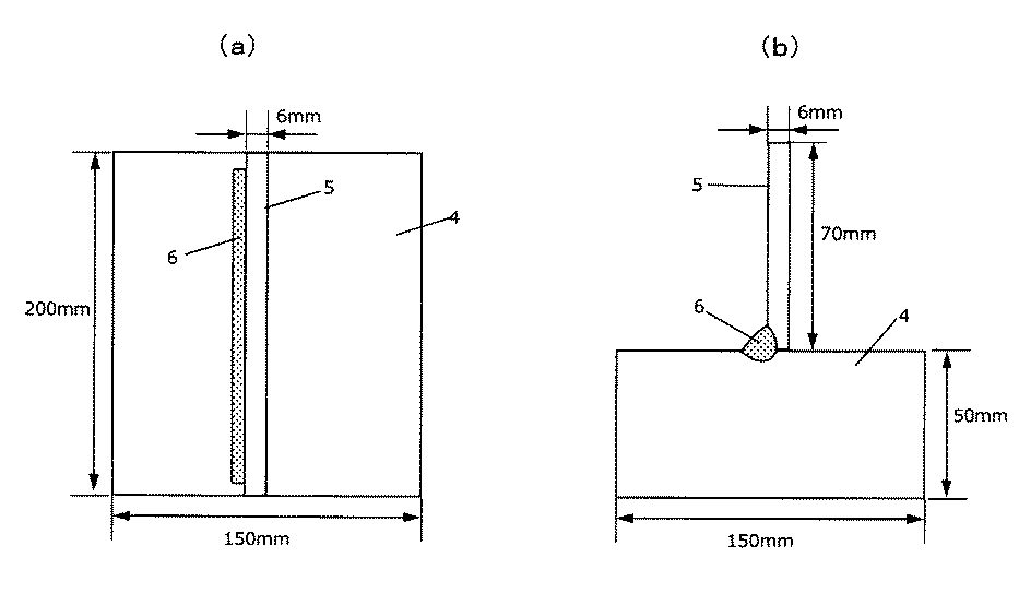
(ビッカース硬さ試験)
図2は単層すみ肉溶接の状態を表す説明図であり、図2(a)は平面図であり、図2(b)は断面図である。図2に示すように、鋼板4としての、幅150mm×長さ200mm×板厚50mmのJIS G3106 SM400B鋼板、及び、鋼板5としての、幅70mm×長さ200mm×板厚6mmのJIS G3106 SM400B鋼板を用意した。これら下板及び立板に対して、表3及び表4に示される種々の組成を有する溶加材(ワイヤ)を使用して、下記表1に示す溶接条件で単層すみ肉溶接部6を作製した。
(Vickers hardness test)
2A and 2B are explanatory views showing a state of single-layer fillet welding, FIG. 2A is a plan view, and FIG. 2B is a cross-sectional view. As shown in FIG. 2, the JIS G3106 SM400B steel plate having a width of 150 mm × the length of 200 mm × the plate thickness of 50 mm as the steel plate 4 and the JIS G3106 SM400B steel plate having a width of 70 mm × the length of 200 mm × the plate thickness of 6 mm as the steel plate 5 I prepared. For these lower plates and standing plates, a filler metal (wire) having various compositions shown in Tables 3 and 4 was used to form a single-layer fillet welded
次に、得られた溶接金属について、下記表2に示す条件で、溶接金属の断面中央部のビッカース硬さ試験を実施することにより、ビッカース硬さHVを測定し、評価した。この結果を表5及び表6に示す。ここで、ビッカース硬さがHV350以下の場合を良好とし、HV350を超える場合を不良(×)として評価した。 Next, the Vickers hardness HV of the obtained weld metal was measured and evaluated by carrying out a Vickers hardness test at the center of the cross section of the weld metal under the conditions shown in Table 2 below. The results are shown in Tables 5 and 6. Here, the case where the Vickers hardness was HV350 or less was evaluated as good, and the case where the Vickers hardness exceeded HV350 was evaluated as defective (x).
実験例1〜11は実施例であり、実験例12〜25は比較例である。
表3〜6に示されるように、実験例1〜11の各溶加材は、適切な化学組成を有しているため、全溶接金属の引張試験における引張強度が430〜600MPaの範囲になると共に、0.2%耐力が330MPa以上、伸びが20%以上の良好な機械的性能が得られた。更に、単層すみ肉溶接金属のビッカース硬さもHV350以下となり、良好であった。したがって、実験例1〜11の各溶加材は、単層溶接における遅れ割れの要因となる溶接金属の過剰硬度を抑制するとともに、多層溶接において400MPa級鋼の溶接材料として求められる溶接継手性能(強度、靱性等)を満足するものであった。
なお、実験例4及び9は[X]がそれぞれ12.7及び11.9と大きいため、スラグ発生量が多く、外観には劣るものであった。
Experimental Examples 1 to 11 are Examples, and Experimental Examples 12 to 25 are Comparative Examples.
As shown in Tables 3 to 6, since each filler metal of Experimental Examples 1 to 11 has an appropriate chemical composition, the tensile strength in the tensile test of all weld metals is in the range of 430 to 600 MPa. At the same time, good mechanical performance with a 0.2% proof stress of 330 MPa or more and an elongation of 20% or more was obtained. Further, the Vickers hardness of the single-layer fillet weld metal was also HV350 or less, which was good. Therefore, each filler metal of Experimental Examples 1 to 11 suppresses the excessive hardness of the weld metal, which causes delayed cracking in single-layer welding, and has welded joint performance required as a welding material for 400 MPa class steel in multi-layer welding. Strength, toughness, etc.) were satisfied.
In Experimental Examples 4 and 9, since [X] was as large as 12.7 and 11.9, respectively, the amount of slag generated was large and the appearance was inferior.
一方、実験例12は、Mn含有量が本発明規定の範囲より小さく、また、Ceqが本発明規定の範囲より小さい。そのため、全溶着金属の0.2%耐力および引張強度が不足し、評価結果が不良であった。
実験例13は、Si含有量が本発明規定の範囲より小さい。そのため、全溶着金属の引張強度が不足し、評価結果が不良であった。
実験例14は、C含有量及びMn含有量が本発明規定の範囲より小さく、また、Ceqが本発明規定の範囲より小さい。そのため、全溶着金属の0.2%耐力および引張強度が不足し、評価結果が不良であった。
On the other hand, in Experimental Example 12, the Mn content is smaller than the range specified in the present invention, and Ceq is smaller than the range specified in the present invention. Therefore, the 0.2% proof stress and tensile strength of the total weld metal were insufficient, and the evaluation result was poor.
In Experimental Example 13, the Si content is smaller than the range specified in the present invention. Therefore, the tensile strength of the fully welded metal was insufficient, and the evaluation result was poor.
In Experimental Example 14, the C content and the Mn content are smaller than the range specified in the present invention, and the Ceq is smaller than the range specified in the present invention. Therefore, the 0.2% proof stress and tensile strength of the total weld metal were insufficient, and the evaluation result was poor.
実験例15は、C含有量、Si含有量、Mn含有量及びMo含有量が本発明規定の範囲より大きく、また、Ceqが本発明規定の範囲より大きい。そのため、全溶着金属の引張強度が高く、評価結果が不良であり、またビッカース硬さもHV350を超過し、評価結果も不良であった。
実験例16は、Si含有量及びMn含有量が本発明規定の範囲より大きく、また、Ceqが本発明規定の範囲より大きい。そのため、全溶着金属の引張強度が高く、評価結果が不良であり、またビッカース硬さもHV350を超過し、評価結果も不良であった。
実験例17は、C含有量が本発明規定の範囲より大きく、また、Ceqが本発明規定の範囲より大きい。そのため、全溶着金属の引張強度が高く、評価結果が不良であり、またビッカース硬さもHV350を超過し、評価結果も不良であった。
In Experimental Example 15, the C content, Si content, Mn content and Mo content are larger than the range specified in the present invention, and Ceq is larger than the range specified in the present invention. Therefore, the tensile strength of the fully welded metal was high, the evaluation result was poor, the Vickers hardness also exceeded HV350, and the evaluation result was also poor.
In Experimental Example 16, the Si content and the Mn content are larger than the range specified in the present invention, and the Ceq is larger than the range specified in the present invention. Therefore, the tensile strength of the fully welded metal was high, the evaluation result was poor, the Vickers hardness also exceeded HV350, and the evaluation result was also poor.
In Experimental Example 17, the C content is larger than the range specified in the present invention, and Ceq is larger than the range specified in the present invention. Therefore, the tensile strength of the fully welded metal was high, the evaluation result was poor, the Vickers hardness also exceeded HV350, and the evaluation result was also poor.
実験例18は、N含有量が本発明規定の範囲より大きい。そのため、全溶着金属の吸収エネルギーが不足し、評価結果が不良であった。 In Experimental Example 18, the N content is larger than the range specified in the present invention. Therefore, the absorbed energy of all the weld metals was insufficient, and the evaluation result was poor.
実験例19は、Si含有量が本発明規定の範囲より小さく、また、S含有量が本発明規定の範囲より大きい。そのため、全溶着金属の引張強度および吸収エネルギーが不足し、評価結果が不良であった。 In Experimental Example 19, the Si content is smaller than the range specified in the present invention, and the S content is larger than the range specified in the present invention. Therefore, the tensile strength and absorbed energy of the fully welded metal were insufficient, and the evaluation result was poor.
実験例20は、Mn含有量が本発明規定の範囲より小さく、また、Ni含有量が本発明規定の範囲より大きい。そのため、全溶着金属の引張強度および0.2%耐力が不足し、評価結果が不良であった。 In Experimental Example 20, the Mn content is smaller than the range specified in the present invention, and the Ni content is larger than the range specified in the present invention. Therefore, the tensile strength and 0.2% proof stress of the fully welded metal were insufficient, and the evaluation result was poor.
実験例21は、Cr含有量が本発明規定の範囲より大きく、また、Ceqも本発明規定の範囲より大きい。そのため、全溶着金属の引張強度およびビッカース硬さが高く、評価結果が不良であった。
実験例22は、Mo含有量が本発明規定の範囲より大きい。そのため、全溶着金属の引張強度およびビッカース硬さが高く、評価結果が不良であった。
実験例23は、Cr含有量、V含有量およびN含有量が本発明規定の範囲より大きい。そのため、全溶着金属の吸収エネルギーが不足し、且つ、ビッカース硬さが高く、評価結果が不良であった。
In Experimental Example 21, the Cr content is larger than the range specified in the present invention, and Ceq is also larger than the range specified in the present invention. Therefore, the tensile strength and Vickers hardness of the fully welded metal were high, and the evaluation result was poor.
In Experimental Example 22, the Mo content is larger than the range specified in the present invention. Therefore, the tensile strength and Vickers hardness of the fully welded metal were high, and the evaluation result was poor.
In Experimental Example 23, the Cr content, V content and N content are larger than the range specified in the present invention. Therefore, the absorbed energy of the total weld metal was insufficient, the Vickers hardness was high, and the evaluation result was poor.
実験例24は、C含有量が本発明規定の範囲より大きく、また、Ceqも本発明規定の範囲より大きい。そのため、全溶着金属の引張強度およびビッカース硬さが高く、評価結果が不良であった。 In Experimental Example 24, the C content is larger than the range specified in the present invention, and Ceq is also larger than the range specified in the present invention. Therefore, the tensile strength and Vickers hardness of the fully welded metal were high, and the evaluation result was poor.
実験例25は、P含有量が本発明規定の範囲より大きい。そのため、全溶着金属の吸収エネルギーが不足し、評価結果が不良であった。また、スラグ発生量が多く、外観に劣るものであった。 In Experimental Example 25, the P content is larger than the range specified in the present invention. Therefore, the absorbed energy of all the weld metals was insufficient, and the evaluation result was poor. In addition, the amount of slag generated was large and the appearance was inferior.
1 鋼板
1a 傾斜面
2 開先
3 裏当て材
4 下板
5 立板
6 溶接金属
1 Steel plate 1a
Claims (4)
Si:0.30〜0.85質量%、及び
Mn:0.70〜1.40質量%を含有し、
Ni:0.10質量%以下(但し、0質量%を含む)、
Cr:0.10質量%以下(但し、0質量%を含む)、
Mo:0.10質量%以下(但し、0質量%を含む)、
V:0.05質量%以下(但し、0質量%を含む)、
P:0.030質量%以下(但し、0質量%を含まない)、
S:0.030質量%以下(但し、0質量%を含まない)、
N:0.0100質量%以下(但し、0質量%を含まない)、及び
O:0.0100質量%以下(但し、0質量%を含まない)にそれぞれ規制され、
残部がFeおよび不可避的不純物からなり、かつ、
下記式(1)で表される炭素当量Ceqが0.15〜0.35の範囲内であるTIG溶接用溶加材。
Ceq=[C]+[Si]/24+[Mn]/6+[Ni]/40+[Cr]/5+[Mo]/4+[V]/14 (1)
(但し、[C]、[Si]、[Mn]、[Ni]、[Cr]、[Mo]および[V]は、それぞれC、Si、Mn、Ni、Cr、MoおよびVの含有量(質量%)を示す。) C: 0.02 to 0.06% by mass,
It contains Si: 0.30 to 0.85% by mass and Mn: 0.70 to 1.40% by mass.
Ni: 0.10% by mass or less (however, including 0% by mass),
Cr: 0.10% by mass or less (however, including 0% by mass),
Mo: 0.10% by mass or less (however, including 0% by mass),
V: 0.05% by mass or less (however, including 0% by mass),
P: 0.030% by mass or less (however, 0% by mass is not included),
S: 0.030% by mass or less (however, 0% by mass is not included) ,
N: 0.0100% by mass or less (however, 0% by mass is not included) , and
O: Regulated to 0.0100% by mass or less (however, 0% by mass is not included)
The balance consists of Fe and unavoidable impurities, and
A filler material for TIG welding in which the carbon equivalent Ceq represented by the following formula (1) is in the range of 0.15 to 0.35.
Ceq = [C] + [Si] / 24 + [Mn] / 6 + [Ni] / 40 + [Cr] / 5 + [Mo] / 4 + [V] / 14 (1)
(However, [C], [Si], [Mn], [Ni], [Cr], [Mo] and [V] are the contents of C, Si, Mn, Ni, Cr, Mo and V, respectively. Mass%) is shown.)
Ti:0.10質量%以下(但し、0質量%を含む)、及び
Zr:0.10質量%以下(但し、0質量%を含む)
からなる群から選ばれる少なくとも1種と、
Cu:0.50質量%以下(但し、0質量%を含まない)と、
をさらに含有し、かつ
下記式(2)の関係を満足する請求項1又は2に記載のTIG溶接用溶加材。
[X]=([Ti]+[Al]+[Zr])×[O]×10000≦10.0 (2)
(但し、[Ti]、[Al]、[Zr]、および[O]は、それぞれTi、Al、ZrおよびOの含有量(質量%)を示す。) Al: 0.10% by mass or less (however, including 0% by mass),
Ti: 0.10% by mass or less (however, including 0% by mass), and Zr: 0.10% by mass or less (however, including 0% by mass )
And at least one selected from Ranaru group or,
Cu: 0.50% by mass or less (however, 0% by mass is not included),
The TIG welding filler material according to claim 1 or 2, which further contains the above and satisfies the relationship of the following formula (2).
[X] = ([Ti] + [Al] + [Zr]) × [O] × 10000 ≦ 10.0 (2)
(However, [Ti], [Al], [Zr], and [O] indicate the contents (mass%) of Ti, Al, Zr, and O, respectively.)
Priority Applications (1)
| Application Number | Priority Date | Filing Date | Title |
|---|---|---|---|
| JP2017039844A JP6829111B2 (en) | 2017-03-02 | 2017-03-02 | Filling material for TIG welding |
Applications Claiming Priority (1)
| Application Number | Priority Date | Filing Date | Title |
|---|---|---|---|
| JP2017039844A JP6829111B2 (en) | 2017-03-02 | 2017-03-02 | Filling material for TIG welding |
Publications (2)
| Publication Number | Publication Date |
|---|---|
| JP2018144060A JP2018144060A (en) | 2018-09-20 |
| JP6829111B2 true JP6829111B2 (en) | 2021-02-10 |
Family
ID=63588589
Family Applications (1)
| Application Number | Title | Priority Date | Filing Date |
|---|---|---|---|
| JP2017039844A Active JP6829111B2 (en) | 2017-03-02 | 2017-03-02 | Filling material for TIG welding |
Country Status (1)
| Country | Link |
|---|---|
| JP (1) | JP6829111B2 (en) |
Families Citing this family (2)
| Publication number | Priority date | Publication date | Assignee | Title |
|---|---|---|---|---|
| CN110711921A (en) * | 2019-11-06 | 2020-01-21 | 中车长春轨道客车股份有限公司 | Welding process method for aluminum alloy medium plate of railway vehicle |
| CN111515502A (en) * | 2020-05-16 | 2020-08-11 | 中国有色金属工业第六冶金建设有限公司 | Copper-nickel alloy welding method |
-
2017
- 2017-03-02 JP JP2017039844A patent/JP6829111B2/en active Active
Also Published As
| Publication number | Publication date |
|---|---|
| JP2018144060A (en) | 2018-09-20 |
Similar Documents
| Publication | Publication Date | Title |
|---|---|---|
| JP5005309B2 (en) | Gas shielded arc welding flux cored wire for high strength steel | |
| JP6766866B2 (en) | Flux-cored wire, welded joint manufacturing method, and welded joint | |
| RU2638483C2 (en) | Wire with flux core | |
| JP4478059B2 (en) | Gas shielded arc welding wire for refractory structural steel. | |
| JP4614226B2 (en) | Solid wire for gas shielded arc welding | |
| WO2015068261A1 (en) | Method for producing weld joint | |
| WO2018087812A1 (en) | Flux-cored wire, method of manufacturing welded joint, and welded joint | |
| CN108698174B (en) | Flux-cored wire, method for manufacturing welded joint, and welded joint | |
| WO2012108517A1 (en) | Weld metal with excellent creep characteristics | |
| WO2014119189A1 (en) | Coated electrode | |
| JP5744816B2 (en) | Bond flux for submerged arc welding | |
| JP6155810B2 (en) | High Ni flux cored wire for gas shielded arc welding | |
| WO2018159719A1 (en) | Fillet welded joint and manufacturing method thereof | |
| JP3871655B2 (en) | Double-sided single layer submerged arc welding wire for high strength steel | |
| JP6829111B2 (en) | Filling material for TIG welding | |
| JP7215911B2 (en) | Flux-cored wire for gas-shielded arc welding | |
| JP3894703B2 (en) | Gas shielded arc welding wire | |
| WO2016060208A1 (en) | Wire containing flux for gas shield arc welding | |
| JP2008264812A (en) | Groove filler for submerged-arc welding | |
| JP2004261858A (en) | Wire for welding martensitic stainless steel pipe | |
| JP4040824B2 (en) | Weld metal | |
| JP7352253B2 (en) | mechanical parts | |
| JP4220088B2 (en) | Welded joint for steel structure and method for producing the same | |
| JP2019118935A (en) | Flux-cored wire for gas shield arc welding, and method for production of weld joint | |
| JP2017164768A (en) | HIGH Ni FLUX-CORED WIRE FOR GAS SHIELDED ARC WELDING AND METHOD OF MANUFACTURING WELDED JOINT |
Legal Events
| Date | Code | Title | Description |
|---|---|---|---|
| A621 | Written request for application examination |
Free format text: JAPANESE INTERMEDIATE CODE: A621 Effective date: 20190930 |
|
| A977 | Report on retrieval |
Free format text: JAPANESE INTERMEDIATE CODE: A971007 Effective date: 20200708 |
|
| A131 | Notification of reasons for refusal |
Free format text: JAPANESE INTERMEDIATE CODE: A131 Effective date: 20200804 |
|
| A521 | Written amendment |
Free format text: JAPANESE INTERMEDIATE CODE: A523 Effective date: 20201005 |
|
| TRDD | Decision of grant or rejection written | ||
| A01 | Written decision to grant a patent or to grant a registration (utility model) |
Free format text: JAPANESE INTERMEDIATE CODE: A01 Effective date: 20210105 |
|
| A61 | First payment of annual fees (during grant procedure) |
Free format text: JAPANESE INTERMEDIATE CODE: A61 Effective date: 20210121 |
|
| R150 | Certificate of patent or registration of utility model |
Ref document number: 6829111 Country of ref document: JP Free format text: JAPANESE INTERMEDIATE CODE: R150 |