EP3472503B1 - A connector for the reciprocal connection of an end member of a water supply or a sprayer and a flexible hose - Google Patents
A connector for the reciprocal connection of an end member of a water supply or a sprayer and a flexible hose Download PDFInfo
- Publication number
- EP3472503B1 EP3472503B1 EP17745865.0A EP17745865A EP3472503B1 EP 3472503 B1 EP3472503 B1 EP 3472503B1 EP 17745865 A EP17745865 A EP 17745865A EP 3472503 B1 EP3472503 B1 EP 3472503B1
- Authority
- EP
- European Patent Office
- Prior art keywords
- flexible hose
- spigot
- connector
- pressure
- annular
- Prior art date
- Legal status (The legal status is an assumption and is not a legal conclusion. Google has not performed a legal analysis and makes no representation as to the accuracy of the status listed.)
- Active
Links
Images


Classifications
-
- F—MECHANICAL ENGINEERING; LIGHTING; HEATING; WEAPONS; BLASTING
- F16—ENGINEERING ELEMENTS AND UNITS; GENERAL MEASURES FOR PRODUCING AND MAINTAINING EFFECTIVE FUNCTIONING OF MACHINES OR INSTALLATIONS; THERMAL INSULATION IN GENERAL
- F16L—PIPES; JOINTS OR FITTINGS FOR PIPES; SUPPORTS FOR PIPES, CABLES OR PROTECTIVE TUBING; MEANS FOR THERMAL INSULATION IN GENERAL
- F16L33/00—Arrangements for connecting hoses to rigid members; Rigid hose-connectors, i.e. single members engaging both hoses
- F16L33/22—Arrangements for connecting hoses to rigid members; Rigid hose-connectors, i.e. single members engaging both hoses with means not mentioned in the preceding groups for gripping the hose between inner and outer parts
- F16L33/223—Arrangements for connecting hoses to rigid members; Rigid hose-connectors, i.e. single members engaging both hoses with means not mentioned in the preceding groups for gripping the hose between inner and outer parts the sealing surfaces being pressed together by means of a member, e.g. a swivel nut, screwed on or into one of the joint parts
- F16L33/224—Arrangements for connecting hoses to rigid members; Rigid hose-connectors, i.e. single members engaging both hoses with means not mentioned in the preceding groups for gripping the hose between inner and outer parts the sealing surfaces being pressed together by means of a member, e.g. a swivel nut, screwed on or into one of the joint parts a clamping ring being arranged between the threaded member and the connecting member
-
- F—MECHANICAL ENGINEERING; LIGHTING; HEATING; WEAPONS; BLASTING
- F16—ENGINEERING ELEMENTS AND UNITS; GENERAL MEASURES FOR PRODUCING AND MAINTAINING EFFECTIVE FUNCTIONING OF MACHINES OR INSTALLATIONS; THERMAL INSULATION IN GENERAL
- F16L—PIPES; JOINTS OR FITTINGS FOR PIPES; SUPPORTS FOR PIPES, CABLES OR PROTECTIVE TUBING; MEANS FOR THERMAL INSULATION IN GENERAL
- F16L19/00—Joints in which sealing surfaces are pressed together by means of a member, e.g. a swivel nut, screwed on, or into, one of the joint parts
- F16L19/06—Joints in which sealing surfaces are pressed together by means of a member, e.g. a swivel nut, screwed on, or into, one of the joint parts in which radial clamping is obtained by wedging action on non-deformed pipe ends
- F16L19/061—Joints in which sealing surfaces are pressed together by means of a member, e.g. a swivel nut, screwed on, or into, one of the joint parts in which radial clamping is obtained by wedging action on non-deformed pipe ends a pressure ring being arranged between the clamping ring and the threaded member or the connecting member
-
- F—MECHANICAL ENGINEERING; LIGHTING; HEATING; WEAPONS; BLASTING
- F16—ENGINEERING ELEMENTS AND UNITS; GENERAL MEASURES FOR PRODUCING AND MAINTAINING EFFECTIVE FUNCTIONING OF MACHINES OR INSTALLATIONS; THERMAL INSULATION IN GENERAL
- F16L—PIPES; JOINTS OR FITTINGS FOR PIPES; SUPPORTS FOR PIPES, CABLES OR PROTECTIVE TUBING; MEANS FOR THERMAL INSULATION IN GENERAL
- F16L19/00—Joints in which sealing surfaces are pressed together by means of a member, e.g. a swivel nut, screwed on, or into, one of the joint parts
- F16L19/06—Joints in which sealing surfaces are pressed together by means of a member, e.g. a swivel nut, screwed on, or into, one of the joint parts in which radial clamping is obtained by wedging action on non-deformed pipe ends
- F16L19/065—Joints in which sealing surfaces are pressed together by means of a member, e.g. a swivel nut, screwed on, or into, one of the joint parts in which radial clamping is obtained by wedging action on non-deformed pipe ends the wedging action being effected by means of a ring
-
- F—MECHANICAL ENGINEERING; LIGHTING; HEATING; WEAPONS; BLASTING
- F16—ENGINEERING ELEMENTS AND UNITS; GENERAL MEASURES FOR PRODUCING AND MAINTAINING EFFECTIVE FUNCTIONING OF MACHINES OR INSTALLATIONS; THERMAL INSULATION IN GENERAL
- F16L—PIPES; JOINTS OR FITTINGS FOR PIPES; SUPPORTS FOR PIPES, CABLES OR PROTECTIVE TUBING; MEANS FOR THERMAL INSULATION IN GENERAL
- F16L29/00—Joints with fluid cut-off means
- F16L29/02—Joints with fluid cut-off means with a cut-off device in one of the two pipe ends, the cut-off device being automatically opened when the coupling is applied
-
- F—MECHANICAL ENGINEERING; LIGHTING; HEATING; WEAPONS; BLASTING
- F16—ENGINEERING ELEMENTS AND UNITS; GENERAL MEASURES FOR PRODUCING AND MAINTAINING EFFECTIVE FUNCTIONING OF MACHINES OR INSTALLATIONS; THERMAL INSULATION IN GENERAL
- F16L—PIPES; JOINTS OR FITTINGS FOR PIPES; SUPPORTS FOR PIPES, CABLES OR PROTECTIVE TUBING; MEANS FOR THERMAL INSULATION IN GENERAL
- F16L33/00—Arrangements for connecting hoses to rigid members; Rigid hose-connectors, i.e. single members engaging both hoses
- F16L33/20—Undivided rings, sleeves, or like members contracted on the hose or expanded inside the hose by means of tools; Arrangements using such members
- F16L33/207—Undivided rings, sleeves, or like members contracted on the hose or expanded inside the hose by means of tools; Arrangements using such members only a sleeve being contracted on the hose
- F16L33/2071—Undivided rings, sleeves, or like members contracted on the hose or expanded inside the hose by means of tools; Arrangements using such members only a sleeve being contracted on the hose the sleeve being a separate connecting member
- F16L33/2078—Undivided rings, sleeves, or like members contracted on the hose or expanded inside the hose by means of tools; Arrangements using such members only a sleeve being contracted on the hose the sleeve being a separate connecting member connected to the rigid member via an intermediate element
-
- F—MECHANICAL ENGINEERING; LIGHTING; HEATING; WEAPONS; BLASTING
- F16—ENGINEERING ELEMENTS AND UNITS; GENERAL MEASURES FOR PRODUCING AND MAINTAINING EFFECTIVE FUNCTIONING OF MACHINES OR INSTALLATIONS; THERMAL INSULATION IN GENERAL
- F16L—PIPES; JOINTS OR FITTINGS FOR PIPES; SUPPORTS FOR PIPES, CABLES OR PROTECTIVE TUBING; MEANS FOR THERMAL INSULATION IN GENERAL
- F16L11/00—Hoses, i.e. flexible pipes
- F16L11/02—Hoses, i.e. flexible pipes made of fibres or threads, e.g. of textile
-
- F—MECHANICAL ENGINEERING; LIGHTING; HEATING; WEAPONS; BLASTING
- F16—ENGINEERING ELEMENTS AND UNITS; GENERAL MEASURES FOR PRODUCING AND MAINTAINING EFFECTIVE FUNCTIONING OF MACHINES OR INSTALLATIONS; THERMAL INSULATION IN GENERAL
- F16L—PIPES; JOINTS OR FITTINGS FOR PIPES; SUPPORTS FOR PIPES, CABLES OR PROTECTIVE TUBING; MEANS FOR THERMAL INSULATION IN GENERAL
- F16L11/00—Hoses, i.e. flexible pipes
- F16L11/04—Hoses, i.e. flexible pipes made of rubber or flexible plastics
- F16L11/12—Hoses, i.e. flexible pipes made of rubber or flexible plastics with arrangements for particular purposes, e.g. specially profiled, with protecting layer, heated, electrically conducting
-
- F—MECHANICAL ENGINEERING; LIGHTING; HEATING; WEAPONS; BLASTING
- F16—ENGINEERING ELEMENTS AND UNITS; GENERAL MEASURES FOR PRODUCING AND MAINTAINING EFFECTIVE FUNCTIONING OF MACHINES OR INSTALLATIONS; THERMAL INSULATION IN GENERAL
- F16L—PIPES; JOINTS OR FITTINGS FOR PIPES; SUPPORTS FOR PIPES, CABLES OR PROTECTIVE TUBING; MEANS FOR THERMAL INSULATION IN GENERAL
- F16L47/00—Connecting arrangements or other fittings specially adapted to be made of plastics or to be used with pipes made of plastics
- F16L47/04—Connecting arrangements or other fittings specially adapted to be made of plastics or to be used with pipes made of plastics with a swivel nut or collar engaging the pipe
Definitions
- the present invention is generally applicable to the technical field of connectors for flexible hoses, and it particularly relates to a connector for the reciprocal connection of an end member of a water supply or of a sprayer and a flexible hose, in particolar a garden hose.
- connectors systems are known to connect flexible hoses to an end member, that may be threaded or not.
- connectors are known to connect garden hoses to the end member of a water supply, for instance a tap connected to the water network, or a sprayer.
- Such connectors generally provide for a main body having a cylindrical spigot that is meant to be inserted inside the hose in correspondence to one end thereof, and a closing element, for example a ring nut that is screwed on the main body to radially compress a portion of the end of the hose against the spigot to obtain the hydraulic seal.
- a closing element for example a ring nut that is screwed on the main body to radially compress a portion of the end of the hose against the spigot to obtain the hydraulic seal.
- Such connectors may be improved. In particolar with regards to the hydraulic seal thereof.
- the known connectors are difficult to be mounted on the hose, especially in the case of an extendible hose.
- Object of the present invention is to at least partially overcome the above mentioned drawbacks, by providing a connector for flexible hoses of high efficiency and relative low cost.
- Another object of the present invention is to provide a connector having a high hydraulic and / or mechanical seal even in case of extendible flexible hoses.
- Another object of the present invention is to provide a connector for flexible hoses that does not twist the hose upon the screwing of the ring nut on the threaded end member.
- Another object of the present invention is to provide a connector for flexible hoses having easy insertion thereon.
- the hose H may be a garden hose to transport irrigation water.
- the hose H may be a conventional flexible hose made, for instance, according to the teachings of European Patent EP0623776 on behalf of the same Applicant, or it may be an extendible flexible hose made, for example, according to the teachings of PCT/IB2016/059765, always on behalf of the same Applicant.
- the hose may be a flexible hose that enlarges under pressure made, for example, according to the teachings of PCT/IB2016/052435, always on behalf of the same Applicant.
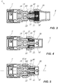
- the connector 1 may comprise a main body 10 of a substantially tubular shape that may define an axis X.
- the main body 10 may have a male or female end portion 11 for the coupling with the end member T and an opposite end portion 12 for the coupling with the hose H.
- the end member T and the main body 10 may be coupled in a per se known manner, for example by means of male-female fast-coupling systems, by means of thread and counter-thread, or the like.
- the end member T may be, for example, a tap connected to the water network or the end of a sprayer.
- the end portion 12 may comprise an abutment wall 13 and an elongated spigot 20 extending from the latter, the spigot may be substantially coaxial to the main body 10. Therefore, the abutment wall 13 may be substantially annular and perpendicular to the axis X.
- the flexible hose H may have at least one end E that may be fitted on the spigot 20 so as the water flows between the flexible hose H and the end member T.
- the spigot 20 may include at least one inlet 21 and one outlet 22 for the water.
- the inner diameter of the end E of the flexible hose H may be substantially equal or slightly lower than the outer diameter of the spigot 20 to allow the former to be fitted on the latter.
- the spigot 20 may be configured so as to facilitate the insertion of the end E of the flexible hose H thereon.
- the spigot 20 may include at least one annular projection, preferably at least two annular projections 23', 23", diverging along the insertion direction of the flexible hose H.
- the annular projections 23', 23" may have a truncated shape having a maximum diameter increasing towards the abutment wall 13 of the main body 10.
- the annular projection 23' distal from the abutment wall 13 may have a maximum diameter lower than the maximum diameter of the annular projection 23" proximal to the abutment wall 13.
- the connector 1 may comprise valve means 50 configured to block the outflow of water from the flexible hose H once the connector 1 is decoupled from the sprayer.
- valve means 50 may comprise a stem 51 with an end plug 52 coaxially inserted through the spigot 20 to selectively block the inlet thereof 21.
- the plug 52 may be diverging along the insertion direction of the flexible hose H so as to facilitate the insertion of the flexible hose H thereof on the spigot 20.
- the plug 52 may have a substantially semi-spherical shape. More particularly, the plug 52 may have a maximum diameter substantially equal to the inner diameter of the spigot 20 so as the latter and the plug 52 cooperate to define a substantially continuous invitation surface.
- the reciprocal configuration of the plug 52 and of the spigot 20 may promote the insertion of the flexible hose H on the latter.
- the flexible hose H and the main body 10 may be coupled so as no water flows from the connector 1 during use.
- At least one portion E1 of the end E of the flexible hose H may be radially pressed against the spigot 20 and then against the annular projections 23', 23" so as to obtain such a hydraulic seal of the connector 1.
- the latter may comprise a substantially tubular shaped ring nut 30 that may be placed peripherally to the spigot 20 so as to remain coaxial to the latter.
- the ring nut 30 and the main body 10 may be reciprocally screwable so as to reciprocally move along the axis X upon the reciprocal twisting.
- the main body 10 may have at least one threaded portion 15, while the ring nut 30 may have at least one respective counter-threaded portion 31 with respect to the former so as they are reciprocally screwable.
- the portion E1 of the flexible hose H may then be interposed between the ring nut 30 and the spigot 20.
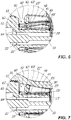
- the latter may be reciprocally configured so as the axial translation of the ring nut 30, that is upon the screwing thereof on the main body 10, corresponds to the radial compression of the portion E1 thereof of the flexible hose H as shown in Fig. 2 .
- the ring nut 30 may have an inner surface 32 at least partially truncated diverging with respect to the coupling direction of the flexible hose H and of the main body 10, that is, with respect to the axis X.
- the connector 1 may comprise an annular pressure element 40 interposed between the ring nut 30 and the spigot 20 coaxially to the latter.
- the pressure element 40 may have a substantially annular edge 42 faced to the abutment wall 13 of the main body 10.
- the ring nut 30, and in particular at least one portion 33 of the inner surface 32 thereof, may interact with the pressure element 40 upon the screwing thereof on the main body 10 so as the latter exerts a radial pressure on the portion E1 of the flexible hose H.
- the end E of the flexible hose H may have an outer surface SE in contact with the inner surface 41 of the pressure element 40, and an inner surface SI in contact with one or more annular projections 23', 23" of the spigot 20 so as to obtain the hydraulic seal of the connector 1.
- the mechanical seal of the connector 1 may also be obtained.
- the pressure element 40 may be of variable configuration.
- the latter may be configured so as upon the screwing of the ring nut 30 the pressure element moves from an enlarged configuration to a contracted configuration to exert the radial pressure on the portion E1 of the flexible hose H.
- the pressure element 40 may have an annular shape and may consist of a substantially truncated shape single body formed by a continuous full-length tubular structure with a constant cross-section.
- the pressure element 40 may exert a uniform pressure on the peripheral development of the portion E1 of the flexible hose H so as to preserve the entirety of the flexible hose H thereof.
- the pressure element 40 thanks to the configuration thereof may be in contact with the outer surface SE of the end E of the flexible hose H during the passage from the enlarged configuration to the contracted configuration.
- the pressure element 40 may radially compress to assume the contracted configuration thus avoiding to rotate around the axis X integrally with the ring nut 30. In this way, upon the coupling with the main body 10, the twisting of the flexible hose H , and particularly of the end E , may be avoided and, therefore, the damage thereof.
- the edge 42 and the abutment wall 13 may be reciprocally spaced apart so as to obtain an annular seat 61 therebetween.
- the end E of the flexible hose H may comprise the portion E1 susceptible to be compressed by the pressure element 40 and a portion E2 susceptible to expand in the annular seat 61 as better explained hereinafter.
- the connector 1 may comprise spacer means 60 to keep the pressure element 40 and the abutment wall 13 reciprocally spaced apart so as to define the thickness of the annular seat 61.
- the spacer means 60 may include a plurality of elongated elements 62 interposed between the pressure element 40 and the abutment wall 13. More in detail, the elongated elements 62 extend from the annular edge 42 of the pressure element 40 to come in contact with the abutment wall 13.
- the pressure element 40 may remain spaced apart from the abutment wall 13 to form the annular seat 61.
- the main body 10, the ring nut 30 and the pressure element 40 may be reciprocally dimensioned and / or configured so as the radial pressure of the latter is exerted more near the annular projection 23" of the spigot 20 proximal to the abutment wall 13, that is, the annular projection opposite to the annular projection 23' proximal to the inlet 21.
- the pressure element 40 may have a substantially truncated configuration.
- annular projection 23" and the spacer means 60 may be reciprocally dimensioned so as the annular projection 23" remains spaced apart from the annular seat 61.
- the elongated elements 62 may have a length such that a tubular interspace 63 cooperating with the annular seat 61 to define an expansion chamber 64 may be defined between the annular projection 23" and the abutment wall 13.
- the portion E2 of the flexible hose H may occupy the expansion chamber 64.
- such a portion E2 may expand due to the pressure variation inside the flexible hose H due to the passage of water inside the flexible hose H thereof.
- tubular interspace 63 may have a narrow portion 63' in correspondence to the annular projection 23" so as sto define an area designed to counteract the pulling of the flexible hose H.
- the space between the annular projection 23" and the annular projection 23' may define a tubular interspace 65.
- the latter may have a narrow portion 65' in correspondence to the annular projection 23' so as to create a further area designed to counteract the pulling of the flexible hose H.
- Such a feature may be particularly advantageous in case the flexible hose H is an extendible hose.
- the user may first insert the ring nut 30 and then the pressure element 40 around the flexible hose H.
- the user may insert the end E of the flexible hose H on the spigot 20 so as the former is close to / in contact with the abutment wall 13.
- the user may screw the latter on the coupling portion 12 of the main body 10 so as to radially compress the pressure element 40 and, therefore, the end E of the flexible hose H so as to obtain a hydraulic and mechanical seal of the connector 1 as described above.
- the connector 1 is particularly advantageous in case of extendible flexible hose H.
- the flexible hose H may have a not corrugated nor coiled tubular structure, typical of irrigation hoses or garden hoses.
- the polymeric layers may be tubular.
- corrugated hose is known from document US3028290
- coiled hose is known from document US4009734 .
- the extendible flexible hose H may comprise at least one inner layer H1 made of a first elastic polymeric material, at least one outer layer H3 made of a second elastic polymeric material and at least one textile reinforcement layer H2 interposed therebetween.
- the at least one inner layer H1 and the at least one outer layer H3 may be coupled therebetween to form a unitary tubular element that embeds, that is, embodies, at least one textile layer H2.
- the at least one outer layer H3 and the at least one inner layer H1 may be reciprocally coupled in correspondence to the areas of the outer surface of the at least one inner layer H1 that are not covered by the textile reinforcment layer H2 .
- the at least one outer layer H3 and the at least one inner layer H1 may be reciproclly coupled except in the areas occupied by the textile yarns of the at least one textile layer H2 .
- the unitary tubular element may have an elasticity such to automatically elongate and enlarge under the working pressure imparted by the liquid flowing therethrough to increase the original length thereof and such to automatically recover once the working pressure stops to assume again the original length and diameter.
- the elongation is considerabe and significant to the naked eye, while the enlargement may be more limited and possibly not significant to the naked eye.
- the first and second elastic polymeric materials that form the unitary tubular element should be suitably chosen.
- the first and second polymeric materials may be elastomers or thermoplastic elastomers (TPE).
- Possible TPE may be TPE-S, such as PP/SEBS or PP/EPDM, or TPE-O, such as Ethylene-Ottene copolymer.
- Possible elastomers may be natural rubber or latex.
- the unitary tubular element as a whole may have a Shore A hardness measured according to ASTM D2240 (3 ") of 30 ShA to 50 ShA.
- the textile yarns that make the at least one textile layer may be polyester, nylon 6,6, Polyvinyl Alcohol, para-aramid fibers, meta-aramid fibers, Rayon®.
- the textile yarns forming the at least one textile layer H2 may have an elongation at break measured according to BISFA (Cap 7) lower than 30% and preferably lower than 25%.
- the textile yarns forming the at least one textile layer H2 may have a toughness measured according to BISFA (Cap 7) of at least 50 cN / tex.
- the conenctor 1 may act as a flow restrictor and it promotes the elongation of the hose H.
- the plug 52 and / or the spigot 20 may act as flow restrictors.
- one of the ends of the hose H may be connected to delivery means of the fluid to be transported, such as a tap, by means of the connector 1.
- the at least one textile reinforcement layer H2 of the extendible flexible hose which may be part of the present invention may be susceptible to move between a rest configuration that it assumes at rest, that is when the liquid does not flow through the unitary tubular element, and a working configuration that it assumes when the unitary tubular element is stressed by the working pressure of the liquid flowing therethrough.
- the at least one textile reinforcement layer H2 axially elongates and radially enlarges to accompany the elongation and the enlargement of the unitary tubular element.
- the yarns forming the textile reinforcement layer may be preferably rigid, so as to effectively act upon the unitary tubular element upon the elongation thereof.
- the at least one textile reinforcement layer and the unitary tubular element may be reciprocally configured so as the former intercepts the latter upon the elongation and enlargement thereof so as to determine the maximum length and diameter thereof.
- the axial elongation and the maximum radial enlargement of the at least one textile reinforcement layer is lower than the axial elongation and the maximum radial enlargement of the unitary tubular element, so that the axial elongation and the maximum radial enlargement of the at least one textile reinforcement layer determines the axial elongation and the maximum radial enlargment of the flexible hose as a whole.
- the automatic recovery of the unitary tubular element may allow the at least one textile reinforcment layer to assume again the rest configuration once the inner pressure of the flexible hose stops.
- Such an automatic recovery of the unitary tubular element may only be accomplished thanks to the elasticity thereof, without any other help.
- the flexible hose which may be part of the present invention may be free of helical springs or similar automatic recovery means.
- the stress of the inner pressure inside the hose may tend not only to axially elongate it, but also to make it expand radially.
- the unitary tubular element may have the original diameter thereof when the at least one textile reinforcement layer is in the rest configuration and an expanded diameter when the at least one textile reinforcement layer is in the working configuration.
- the flexible hose H may comprise at least one first textile layer H2 and at least one second textile layer H2', reciprocally superimposed but not necessarily in reciprocal contact.
- the at least one first textile layer H2 and the unitary tubular element may be reciprocally configured so as the former intercepts the latter upon the elongation thereof to determine the maximum length thereof, while the at least one second textile layer H2 ' and the unitary tubular element may be reciprocally configured so as the former intercepts the latter upon the enlargment thereof so as to determine the maximum diameter thereof.
- the extendible flexible hose H may be realized by means of a method that may sequentially comprise the following steps: a) providing of the at least one inner layer; b) making on the at least one inner layer of the at least one textile reinforcement layer to produce a semi-finished product; and c) extrusion on the semi-finished product of the at least one outer layer.
- the step c) of extrusion of the at least one outer layer may include a step of coupling of the latter and of the at least one inner layer to form the unitary tubular element so as the at least one textile layer is embedded therein.
- the first and second elastic polymeric materials may be reciprocally compatible so as the coupling between the at least one inner layer and the at least one outer layer is accomplished upon the step of c) of extrusion of the at least one outer layer.
- the steps b) of making of the at least one textile reinforcment layer and c) of extrusion of the at least one outer layer may be realized with the at least one inner layer elongated with respect to the original length thereof.
- the elongation step of the at least one inner layer may be accomplished by drawing theteof, preferably by means of two or more pairs of rotating facing cylinders susceptible to press the hose.
- a first pair of cylinders may press the hose before step b) of making of the at least one textile reinforcement layer, while a second pair may press the hose after step c) of extrusion of the at least one outer layer.
- the second pair of cylinders may rotate faster than the first pair of cylinders.
- the at least one inner layer may internally include a detachable film.
Landscapes
- Engineering & Computer Science (AREA)
- General Engineering & Computer Science (AREA)
- Mechanical Engineering (AREA)
- Rigid Pipes And Flexible Pipes (AREA)
- Joints Allowing Movement (AREA)
- Domestic Plumbing Installations (AREA)
- Joints That Cut Off Fluids, And Hose Joints (AREA)
- Details Or Accessories Of Spraying Plant Or Apparatus (AREA)
Applications Claiming Priority (3)
| Application Number | Priority Date | Filing Date | Title |
|---|---|---|---|
| ITUA2016A004384A ITUA20164384A1 (it) | 2016-06-15 | 2016-06-15 | Raccordo per il collegamento reciproco di un terminale di un’utenza o un accessorio diffusore e di un tubo flessibile |
| ITUA2016A004385A ITUA20164385A1 (it) | 2016-06-15 | 2016-06-15 | Raccordo per il collegamento reciproco di un terminale di un’utenza o un accessorio diffusore e di un tubo flessibile |
| PCT/IB2017/053560 WO2017216750A1 (en) | 2016-06-15 | 2017-06-15 | A connector for the reciprocal connection of an end member of a water supply or a sprayer and a flexible hose |
Publications (2)
| Publication Number | Publication Date |
|---|---|
| EP3472503A1 EP3472503A1 (en) | 2019-04-24 |
| EP3472503B1 true EP3472503B1 (en) | 2021-02-17 |
Family
ID=59485382
Family Applications (1)
| Application Number | Title | Priority Date | Filing Date |
|---|---|---|---|
| EP17745865.0A Active EP3472503B1 (en) | 2016-06-15 | 2017-06-15 | A connector for the reciprocal connection of an end member of a water supply or a sprayer and a flexible hose |
Country Status (8)
| Country | Link |
|---|---|
| US (1) | US10746334B2 (enExample) |
| EP (1) | EP3472503B1 (enExample) |
| JP (1) | JP2019526019A (enExample) |
| CN (1) | CN109477603B (enExample) |
| AU (1) | AU2017286781A1 (enExample) |
| CA (1) | CA3027319A1 (enExample) |
| ES (1) | ES2863304T3 (enExample) |
| WO (1) | WO2017216750A1 (enExample) |
Families Citing this family (2)
| Publication number | Priority date | Publication date | Assignee | Title |
|---|---|---|---|---|
| EP3146251B2 (en) † | 2014-05-20 | 2022-03-02 | Paolo De Nora | Extensible hose and hose assembly |
| CN110553103A (zh) | 2019-08-26 | 2019-12-10 | 阳江市新特体育科技用品有限公司 | 一种新型伸缩水管及其制造方法 |
Citations (1)
| Publication number | Priority date | Publication date | Assignee | Title |
|---|---|---|---|---|
| FR2522388A1 (fr) * | 1982-02-26 | 1983-09-02 | Uniflex Utiltime Spa | Raccord pour la liaison de tubes flexibles de diametre notablement different |
Family Cites Families (16)
| Publication number | Priority date | Publication date | Assignee | Title |
|---|---|---|---|---|
| US3980325A (en) * | 1973-04-12 | 1976-09-14 | Duane D. Robertson | Fitting for flexible plastic pipe |
| US4257629A (en) * | 1978-05-01 | 1981-03-24 | Rain Bird Sprinkler Mfg. Corp. | Flexible conduit repair coupling |
| FR2468826A1 (fr) | 1979-10-31 | 1981-05-08 | Capri Codec Sa | Raccord pour tuyau de transport de fluide |
| JPH0177188U (enExample) * | 1987-11-12 | 1989-05-24 | ||
| FR2703755B1 (fr) * | 1993-04-05 | 1995-06-16 | Legris Sa | Dispositif de raccordement d'un tuyau souple a un embout rigide. |
| FR2729454A1 (fr) * | 1995-01-16 | 1996-07-19 | Staubli Sa Ets | Raccord rapide de securite pour la jonction amovible de canalisations |
| IT1294125B1 (it) * | 1997-04-29 | 1999-03-22 | Uniflex Utiltime | Raccordo rapido per tubi flessibili di diametri diversi |
| JP4434930B2 (ja) * | 2004-11-30 | 2010-03-17 | 株式会社十川ゴム | シール部材及び接続部のシール構造 |
| JP4403460B2 (ja) * | 2005-02-09 | 2010-01-27 | 株式会社トヨックス | ホース継手 |
| DE102005011958B3 (de) * | 2005-03-14 | 2006-06-22 | Uponor Innovation Ab | Klemmfitting für ein Heizungs- und/oder Sanitärrohr |
| US7699290B2 (en) * | 2007-08-20 | 2010-04-20 | Jen-Chih Chang | Connection device for quickly connecting pneumatic hose |
| CA2708484A1 (en) * | 2010-06-23 | 2011-12-23 | Fitt S.P.A. | Flexible braided garden hose |
| ITVI20100217A1 (it) * | 2010-07-30 | 2012-01-31 | Fitt Spa | Struttura di tubo flessibile con rinforzo interlacciato |
| ITRN20110078A1 (it) * | 2011-11-11 | 2013-05-12 | Bucchi S R L | Dispositivo di collegamento per tubi flessibili. |
| DE202015100073U1 (de) | 2015-01-09 | 2015-02-09 | Shanghai Q Mall & Co., Ltd. | Automatisch teleskopierbarer Dehnungswasserschlauch mit verlängerter Lebensdauer |
| DE202015106514U1 (de) * | 2015-11-30 | 2016-01-07 | Alfons Markert + Co. Gmbh | Schlauchanschluss |
-
2017
- 2017-06-15 JP JP2018565688A patent/JP2019526019A/ja active Pending
- 2017-06-15 EP EP17745865.0A patent/EP3472503B1/en active Active
- 2017-06-15 US US15/754,262 patent/US10746334B2/en active Active
- 2017-06-15 CA CA3027319A patent/CA3027319A1/en active Pending
- 2017-06-15 CN CN201780045869.XA patent/CN109477603B/zh active Active
- 2017-06-15 ES ES17745865T patent/ES2863304T3/es active Active
- 2017-06-15 AU AU2017286781A patent/AU2017286781A1/en not_active Abandoned
- 2017-06-15 WO PCT/IB2017/053560 patent/WO2017216750A1/en not_active Ceased
Patent Citations (2)
| Publication number | Priority date | Publication date | Assignee | Title |
|---|---|---|---|---|
| FR2522388A1 (fr) * | 1982-02-26 | 1983-09-02 | Uniflex Utiltime Spa | Raccord pour la liaison de tubes flexibles de diametre notablement different |
| IT1214330B (it) * | 1982-02-26 | 1990-01-10 | Uniflex Utiltime Spa | Raccordo per connessione di tubi flessibili di diametro notevolmente vario. |
Also Published As
| Publication number | Publication date |
|---|---|
| CN109477603A (zh) | 2019-03-15 |
| ES2863304T3 (es) | 2021-10-11 |
| NZ749188A (en) | 2024-09-27 |
| AU2017286781A1 (en) | 2019-01-03 |
| JP2019526019A (ja) | 2019-09-12 |
| EP3472503A1 (en) | 2019-04-24 |
| WO2017216750A1 (en) | 2017-12-21 |
| US20190093806A1 (en) | 2019-03-28 |
| CN109477603B (zh) | 2021-02-02 |
| CA3027319A1 (en) | 2017-12-21 |
| US10746334B2 (en) | 2020-08-18 |
Similar Documents
| Publication | Publication Date | Title |
|---|---|---|
| US8230573B2 (en) | Hose connecting method and connector arrangement | |
| US10995886B2 (en) | Metal garden hose with strain relief | |
| EP0739469B1 (en) | Hose assembly, hose coupling and a part therefor and methods of making the same | |
| CN106104129A (zh) | 伸缩软管 | |
| RU2735459C2 (ru) | Шланговое устройство | |
| EP3472503B1 (en) | A connector for the reciprocal connection of an end member of a water supply or a sprayer and a flexible hose | |
| US8590089B2 (en) | Automatic swimming pool cleaners and associated hoses | |
| CN101660637A (zh) | 用于引水系统的压力软管 | |
| KR20110022519A (ko) | 스프링쿨러 권출배관 | |
| EP0531068A2 (en) | Pipe couplings | |
| TWM506913U (zh) | 伸縮水管 | |
| CN114829822B (zh) | 用于软管联接器的联接部件 | |
| EP1332307A1 (en) | Extensible hose device for delivering a fluid | |
| KR102195425B1 (ko) | 샤워기용 호스 | |
| JP2019526019A5 (enExample) | ||
| US20110316273A1 (en) | Dual seal tube fitting | |
| JP7053046B2 (ja) | ホース金具 | |
| WO2016088831A1 (ja) | 管継手及びシャワーホース接続構造 | |
| ITUA20164385A1 (it) | Raccordo per il collegamento reciproco di un terminale di un’utenza o un accessorio diffusore e di un tubo flessibile | |
| ITUA20164384A1 (it) | Raccordo per il collegamento reciproco di un terminale di un’utenza o un accessorio diffusore e di un tubo flessibile | |
| DE20308498U1 (de) | Quetschventil | |
| US20200284380A1 (en) | Fire hydrant nozzle | |
| DE1775686A1 (de) | Stuetzelement zur Verstaerkung von nachgiebigen Rohren,insbesondere von Rohren aus Kunststoff | |
| JP2025073553A (ja) | 液体散布杆 | |
| GB2399149A (en) | A spigot and socket connection primarily for use in a bladder pump |
Legal Events
| Date | Code | Title | Description |
|---|---|---|---|
| STAA | Information on the status of an ep patent application or granted ep patent |
Free format text: STATUS: UNKNOWN |
|
| STAA | Information on the status of an ep patent application or granted ep patent |
Free format text: STATUS: THE INTERNATIONAL PUBLICATION HAS BEEN MADE |
|
| PUAI | Public reference made under article 153(3) epc to a published international application that has entered the european phase |
Free format text: ORIGINAL CODE: 0009012 |
|
| STAA | Information on the status of an ep patent application or granted ep patent |
Free format text: STATUS: REQUEST FOR EXAMINATION WAS MADE |
|
| 17P | Request for examination filed |
Effective date: 20190115 |
|
| AK | Designated contracting states |
Kind code of ref document: A1 Designated state(s): AL AT BE BG CH CY CZ DE DK EE ES FI FR GB GR HR HU IE IS IT LI LT LU LV MC MK MT NL NO PL PT RO RS SE SI SK SM TR |
|
| AX | Request for extension of the european patent |
Extension state: BA ME |
|
| DAV | Request for validation of the european patent (deleted) | ||
| DAX | Request for extension of the european patent (deleted) | ||
| STAA | Information on the status of an ep patent application or granted ep patent |
Free format text: STATUS: EXAMINATION IS IN PROGRESS |
|
| 17Q | First examination report despatched |
Effective date: 20200506 |
|
| GRAP | Despatch of communication of intention to grant a patent |
Free format text: ORIGINAL CODE: EPIDOSNIGR1 |
|
| STAA | Information on the status of an ep patent application or granted ep patent |
Free format text: STATUS: GRANT OF PATENT IS INTENDED |
|
| INTG | Intention to grant announced |
Effective date: 20201110 |
|
| GRAS | Grant fee paid |
Free format text: ORIGINAL CODE: EPIDOSNIGR3 |
|
| GRAA | (expected) grant |
Free format text: ORIGINAL CODE: 0009210 |
|
| STAA | Information on the status of an ep patent application or granted ep patent |
Free format text: STATUS: THE PATENT HAS BEEN GRANTED |
|
| AK | Designated contracting states |
Kind code of ref document: B1 Designated state(s): AL AT BE BG CH CY CZ DE DK EE ES FI FR GB GR HR HU IE IS IT LI LT LU LV MC MK MT NL NO PL PT RO RS SE SI SK SM TR |
|
| REG | Reference to a national code |
Ref country code: GB Ref legal event code: FG4D |
|
| REG | Reference to a national code |
Ref country code: CH Ref legal event code: EP |
|
| REG | Reference to a national code |
Ref country code: DE Ref legal event code: R096 Ref document number: 602017032713 Country of ref document: DE |
|
| REG | Reference to a national code |
Ref country code: AT Ref legal event code: REF Ref document number: 1361921 Country of ref document: AT Kind code of ref document: T Effective date: 20210315 |
|
| REG | Reference to a national code |
Ref country code: IE Ref legal event code: FG4D |
|
| REG | Reference to a national code |
Ref country code: NL Ref legal event code: FP |
|
| REG | Reference to a national code |
Ref country code: LT Ref legal event code: MG9D |
|
| PG25 | Lapsed in a contracting state [announced via postgrant information from national office to epo] |
Ref country code: GR Free format text: LAPSE BECAUSE OF FAILURE TO SUBMIT A TRANSLATION OF THE DESCRIPTION OR TO PAY THE FEE WITHIN THE PRESCRIBED TIME-LIMIT Effective date: 20210518 Ref country code: HR Free format text: LAPSE BECAUSE OF FAILURE TO SUBMIT A TRANSLATION OF THE DESCRIPTION OR TO PAY THE FEE WITHIN THE PRESCRIBED TIME-LIMIT Effective date: 20210217 Ref country code: FI Free format text: LAPSE BECAUSE OF FAILURE TO SUBMIT A TRANSLATION OF THE DESCRIPTION OR TO PAY THE FEE WITHIN THE PRESCRIBED TIME-LIMIT Effective date: 20210217 Ref country code: NO Free format text: LAPSE BECAUSE OF FAILURE TO SUBMIT A TRANSLATION OF THE DESCRIPTION OR TO PAY THE FEE WITHIN THE PRESCRIBED TIME-LIMIT Effective date: 20210517 Ref country code: PT Free format text: LAPSE BECAUSE OF FAILURE TO SUBMIT A TRANSLATION OF THE DESCRIPTION OR TO PAY THE FEE WITHIN THE PRESCRIBED TIME-LIMIT Effective date: 20210617 Ref country code: LT Free format text: LAPSE BECAUSE OF FAILURE TO SUBMIT A TRANSLATION OF THE DESCRIPTION OR TO PAY THE FEE WITHIN THE PRESCRIBED TIME-LIMIT Effective date: 20210217 Ref country code: BG Free format text: LAPSE BECAUSE OF FAILURE TO SUBMIT A TRANSLATION OF THE DESCRIPTION OR TO PAY THE FEE WITHIN THE PRESCRIBED TIME-LIMIT Effective date: 20210517 |
|
| PG25 | Lapsed in a contracting state [announced via postgrant information from national office to epo] |
Ref country code: SE Free format text: LAPSE BECAUSE OF FAILURE TO SUBMIT A TRANSLATION OF THE DESCRIPTION OR TO PAY THE FEE WITHIN THE PRESCRIBED TIME-LIMIT Effective date: 20210217 Ref country code: LV Free format text: LAPSE BECAUSE OF FAILURE TO SUBMIT A TRANSLATION OF THE DESCRIPTION OR TO PAY THE FEE WITHIN THE PRESCRIBED TIME-LIMIT Effective date: 20210217 Ref country code: PL Free format text: LAPSE BECAUSE OF FAILURE TO SUBMIT A TRANSLATION OF THE DESCRIPTION OR TO PAY THE FEE WITHIN THE PRESCRIBED TIME-LIMIT Effective date: 20210217 Ref country code: RS Free format text: LAPSE BECAUSE OF FAILURE TO SUBMIT A TRANSLATION OF THE DESCRIPTION OR TO PAY THE FEE WITHIN THE PRESCRIBED TIME-LIMIT Effective date: 20210217 |
|
| PG25 | Lapsed in a contracting state [announced via postgrant information from national office to epo] |
Ref country code: IS Free format text: LAPSE BECAUSE OF FAILURE TO SUBMIT A TRANSLATION OF THE DESCRIPTION OR TO PAY THE FEE WITHIN THE PRESCRIBED TIME-LIMIT Effective date: 20210617 |
|
| REG | Reference to a national code |
Ref country code: ES Ref legal event code: FG2A Ref document number: 2863304 Country of ref document: ES Kind code of ref document: T3 Effective date: 20211011 |
|
| PG25 | Lapsed in a contracting state [announced via postgrant information from national office to epo] |
Ref country code: SM Free format text: LAPSE BECAUSE OF FAILURE TO SUBMIT A TRANSLATION OF THE DESCRIPTION OR TO PAY THE FEE WITHIN THE PRESCRIBED TIME-LIMIT Effective date: 20210217 Ref country code: CZ Free format text: LAPSE BECAUSE OF FAILURE TO SUBMIT A TRANSLATION OF THE DESCRIPTION OR TO PAY THE FEE WITHIN THE PRESCRIBED TIME-LIMIT Effective date: 20210217 Ref country code: EE Free format text: LAPSE BECAUSE OF FAILURE TO SUBMIT A TRANSLATION OF THE DESCRIPTION OR TO PAY THE FEE WITHIN THE PRESCRIBED TIME-LIMIT Effective date: 20210217 |
|
| REG | Reference to a national code |
Ref country code: DE Ref legal event code: R097 Ref document number: 602017032713 Country of ref document: DE |
|
| PG25 | Lapsed in a contracting state [announced via postgrant information from national office to epo] |
Ref country code: RO Free format text: LAPSE BECAUSE OF FAILURE TO SUBMIT A TRANSLATION OF THE DESCRIPTION OR TO PAY THE FEE WITHIN THE PRESCRIBED TIME-LIMIT Effective date: 20210217 Ref country code: DK Free format text: LAPSE BECAUSE OF FAILURE TO SUBMIT A TRANSLATION OF THE DESCRIPTION OR TO PAY THE FEE WITHIN THE PRESCRIBED TIME-LIMIT Effective date: 20210217 Ref country code: SK Free format text: LAPSE BECAUSE OF FAILURE TO SUBMIT A TRANSLATION OF THE DESCRIPTION OR TO PAY THE FEE WITHIN THE PRESCRIBED TIME-LIMIT Effective date: 20210217 |
|
| PLBE | No opposition filed within time limit |
Free format text: ORIGINAL CODE: 0009261 |
|
| STAA | Information on the status of an ep patent application or granted ep patent |
Free format text: STATUS: NO OPPOSITION FILED WITHIN TIME LIMIT |
|
| 26N | No opposition filed |
Effective date: 20211118 |
|
| PG25 | Lapsed in a contracting state [announced via postgrant information from national office to epo] |
Ref country code: AL Free format text: LAPSE BECAUSE OF FAILURE TO SUBMIT A TRANSLATION OF THE DESCRIPTION OR TO PAY THE FEE WITHIN THE PRESCRIBED TIME-LIMIT Effective date: 20210217 Ref country code: MC Free format text: LAPSE BECAUSE OF FAILURE TO SUBMIT A TRANSLATION OF THE DESCRIPTION OR TO PAY THE FEE WITHIN THE PRESCRIBED TIME-LIMIT Effective date: 20210217 |
|
| PG25 | Lapsed in a contracting state [announced via postgrant information from national office to epo] |
Ref country code: SI Free format text: LAPSE BECAUSE OF FAILURE TO SUBMIT A TRANSLATION OF THE DESCRIPTION OR TO PAY THE FEE WITHIN THE PRESCRIBED TIME-LIMIT Effective date: 20210217 |
|
| PG25 | Lapsed in a contracting state [announced via postgrant information from national office to epo] |
Ref country code: LU Free format text: LAPSE BECAUSE OF NON-PAYMENT OF DUE FEES Effective date: 20210615 |
|
| PG25 | Lapsed in a contracting state [announced via postgrant information from national office to epo] |
Ref country code: IE Free format text: LAPSE BECAUSE OF NON-PAYMENT OF DUE FEES Effective date: 20210615 |
|
| PG25 | Lapsed in a contracting state [announced via postgrant information from national office to epo] |
Ref country code: IS Free format text: LAPSE BECAUSE OF FAILURE TO SUBMIT A TRANSLATION OF THE DESCRIPTION OR TO PAY THE FEE WITHIN THE PRESCRIBED TIME-LIMIT Effective date: 20210617 |
|
| REG | Reference to a national code |
Ref country code: AT Ref legal event code: UEP Ref document number: 1361921 Country of ref document: AT Kind code of ref document: T Effective date: 20210217 |
|
| PG25 | Lapsed in a contracting state [announced via postgrant information from national office to epo] |
Ref country code: CY Free format text: LAPSE BECAUSE OF FAILURE TO SUBMIT A TRANSLATION OF THE DESCRIPTION OR TO PAY THE FEE WITHIN THE PRESCRIBED TIME-LIMIT Effective date: 20210217 |
|
| PG25 | Lapsed in a contracting state [announced via postgrant information from national office to epo] |
Ref country code: HU Free format text: LAPSE BECAUSE OF FAILURE TO SUBMIT A TRANSLATION OF THE DESCRIPTION OR TO PAY THE FEE WITHIN THE PRESCRIBED TIME-LIMIT; INVALID AB INITIO Effective date: 20170615 |
|
| PG25 | Lapsed in a contracting state [announced via postgrant information from national office to epo] |
Ref country code: MK Free format text: LAPSE BECAUSE OF FAILURE TO SUBMIT A TRANSLATION OF THE DESCRIPTION OR TO PAY THE FEE WITHIN THE PRESCRIBED TIME-LIMIT Effective date: 20210217 |
|
| PG25 | Lapsed in a contracting state [announced via postgrant information from national office to epo] |
Ref country code: MT Free format text: LAPSE BECAUSE OF FAILURE TO SUBMIT A TRANSLATION OF THE DESCRIPTION OR TO PAY THE FEE WITHIN THE PRESCRIBED TIME-LIMIT Effective date: 20210217 |
|
| PGFP | Annual fee paid to national office [announced via postgrant information from national office to epo] |
Ref country code: DE Payment date: 20250618 Year of fee payment: 9 |
|
| PGFP | Annual fee paid to national office [announced via postgrant information from national office to epo] |
Ref country code: GB Payment date: 20250618 Year of fee payment: 9 |
|
| PGFP | Annual fee paid to national office [announced via postgrant information from national office to epo] |
Ref country code: NL Payment date: 20250618 Year of fee payment: 9 Ref country code: BE Payment date: 20250618 Year of fee payment: 9 |
|
| PGFP | Annual fee paid to national office [announced via postgrant information from national office to epo] |
Ref country code: FR Payment date: 20250625 Year of fee payment: 9 |
|
| PGFP | Annual fee paid to national office [announced via postgrant information from national office to epo] |
Ref country code: AT Payment date: 20250620 Year of fee payment: 9 |
|
| PGFP | Annual fee paid to national office [announced via postgrant information from national office to epo] |
Ref country code: ES Payment date: 20250728 Year of fee payment: 9 |
|
| PGFP | Annual fee paid to national office [announced via postgrant information from national office to epo] |
Ref country code: IT Payment date: 20250624 Year of fee payment: 9 |
|
| PGFP | Annual fee paid to national office [announced via postgrant information from national office to epo] |
Ref country code: CH Payment date: 20250701 Year of fee payment: 9 |
|
| PG25 | Lapsed in a contracting state [announced via postgrant information from national office to epo] |
Ref country code: TR Free format text: LAPSE BECAUSE OF FAILURE TO SUBMIT A TRANSLATION OF THE DESCRIPTION OR TO PAY THE FEE WITHIN THE PRESCRIBED TIME-LIMIT Effective date: 20210217 |