EP3470710A1 - Struktur zur abdichtung eines zylinderblocks und zylinderkopfs - Google Patents
Struktur zur abdichtung eines zylinderblocks und zylinderkopfs Download PDFInfo
- Publication number
- EP3470710A1 EP3470710A1 EP17810008.7A EP17810008A EP3470710A1 EP 3470710 A1 EP3470710 A1 EP 3470710A1 EP 17810008 A EP17810008 A EP 17810008A EP 3470710 A1 EP3470710 A1 EP 3470710A1
- Authority
- EP
- European Patent Office
- Prior art keywords
- cylinder
- cylinder block
- cylinder head
- circular recess
- peripheral surface
- Prior art date
- Legal status (The legal status is an assumption and is not a legal conclusion. Google has not performed a legal analysis and makes no representation as to the accuracy of the status listed.)
- Granted
Links
Images



Classifications
-
- F—MECHANICAL ENGINEERING; LIGHTING; HEATING; WEAPONS; BLASTING
- F02—COMBUSTION ENGINES; HOT-GAS OR COMBUSTION-PRODUCT ENGINE PLANTS
- F02F—CYLINDERS, PISTONS OR CASINGS, FOR COMBUSTION ENGINES; ARRANGEMENTS OF SEALINGS IN COMBUSTION ENGINES
- F02F11/00—Arrangements of sealings in combustion engines
- F02F11/002—Arrangements of sealings in combustion engines involving cylinder heads
-
- F—MECHANICAL ENGINEERING; LIGHTING; HEATING; WEAPONS; BLASTING
- F16—ENGINEERING ELEMENTS AND UNITS; GENERAL MEASURES FOR PRODUCING AND MAINTAINING EFFECTIVE FUNCTIONING OF MACHINES OR INSTALLATIONS; THERMAL INSULATION IN GENERAL
- F16J—PISTONS; CYLINDERS; SEALINGS
- F16J15/00—Sealings
- F16J15/02—Sealings between relatively-stationary surfaces
- F16J15/06—Sealings between relatively-stationary surfaces with solid packing compressed between sealing surfaces
- F16J15/10—Sealings between relatively-stationary surfaces with solid packing compressed between sealing surfaces with non-metallic packing
- F16J15/104—Sealings between relatively-stationary surfaces with solid packing compressed between sealing surfaces with non-metallic packing characterised by structure
-
- F—MECHANICAL ENGINEERING; LIGHTING; HEATING; WEAPONS; BLASTING
- F02—COMBUSTION ENGINES; HOT-GAS OR COMBUSTION-PRODUCT ENGINE PLANTS
- F02F—CYLINDERS, PISTONS OR CASINGS, FOR COMBUSTION ENGINES; ARRANGEMENTS OF SEALINGS IN COMBUSTION ENGINES
- F02F11/00—Arrangements of sealings in combustion engines
-
- F—MECHANICAL ENGINEERING; LIGHTING; HEATING; WEAPONS; BLASTING
- F16—ENGINEERING ELEMENTS AND UNITS; GENERAL MEASURES FOR PRODUCING AND MAINTAINING EFFECTIVE FUNCTIONING OF MACHINES OR INSTALLATIONS; THERMAL INSULATION IN GENERAL
- F16J—PISTONS; CYLINDERS; SEALINGS
- F16J15/00—Sealings
- F16J15/02—Sealings between relatively-stationary surfaces
- F16J15/06—Sealings between relatively-stationary surfaces with solid packing compressed between sealing surfaces
- F16J15/10—Sealings between relatively-stationary surfaces with solid packing compressed between sealing surfaces with non-metallic packing
Definitions
- the present invention relates to a structure for sealing a cylinder block and a cylinder head. Specifically, the present invention relates to a structure for sealing a cylinder block and a cylinder head capable of reducing a fastening load so as to reduce counterforce and ensuring sealing properties of the periphery of a cylinder bore while implementing reduction in fastening rigidity.
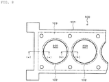
- examples of this kind of cylinder head gasket include a cylinder head gasket 100 in which a plurality of metal plates 101 having beads 102 formed thereon are laminated with a sub plate(shim) 103 sandwiched therebetween (Patent Documents 1 and 2).
- This cylinder head gasket 100 can enhance sealing pressure because the sub plate 103 sandwiched between the metal plates 101 enables a load to be concentrated on the periphery of a cylinder bore 200.
- An object of the present invention is to provide a structure for sealing a cylinder block and a cylinder head capable of reducing a fastening load so as to reduce counterforce, reducing weight due to reduction in fastening rigidity, and ensuring sealing properties of the periphery of a cylinder bore.
- the present invention can provide a structure for sealing a cylinder block and a cylinder head capable of reducing a fastening load so as to reduce counterforce, reducing weight due to reduction in fastening rigidity, and ensuring sealing properties of the periphery of a cylinder bore.
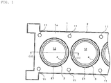
- FIG. 1 is a plan view illustrating a structure for sealing a cylinder block and a cylinder head according to an embodiment of the present invention.
- FIG. 2 is an enlarged cross-sectional view along line ii-ii in FIG. 1 .
- FIG. 3 is a perspective view illustrating an example of a gasket that is partially broken.
- the cylinder block and the cylinder head are indicated by a solid line and a dot-and-dash line, respectively.
- a cylinder head 2 is placed on an upper surface 1a of a cylinder block 1 with a gasket 3 sandwiched therebetween, and is integrally fastened to the cylinder block 1 by unillustrated bolts that are inserted in bolt holes 11 across the cylinder block 1 and the cylinder head 2.
- the cylinder block 1 include cylinder bores 12. Each of the cylinder bores 12 forms a combustion chamber of an engine, and has an unillustrated piston slidably disposed therein. In the cylinder bore 12, a cylindrical sleeve 4 is installed to improve wear resistance to piston sliding. The inner periphery of the cylinder bore 12 is formed with the inner periphery of the sleeve 4.
- An upper end part of the sleeve 4 vertically protrudes from the upper surface 1a of the cylinder block 1 to a predetermined height.
- a cylindrical part 41 formed with the upper end part of the sleeve 4 protrudes concentrically with the cylinder bore 12 so as to enclose the cylinder bore 12 from the upper surface 1a of the cylinder block 1.
- This cylindrical part 41 is formed by difference in height between an upper end surface 41b of the sleeve 4 and the upper surface 1a of the cylinder block 1.
- the cylindrical part 41 may be formed by extending the upper end part of the sleeve 4 by a predetermined height, and may be formed by recessing (shaving) the upper surface 1a of the cylinder block 1 on the outer side of the sleeve 4 at a predetermined depth.
- a circular recess 21 is formed on a lower surface 2a of the cylinder head 2 facing the upper surface 1a of the cylinder block 1.
- This circular recess 21 has a shape where a part corresponding to the cylinder bore 12 is vertically recessed from the lower surface 2a of the cylinder head 2 to a predetermined depth concentrically with the cylinder bore 12.
- This circular recess 21 is formed by difference in height between an inner bottom surface 21b of the circular recess 21 and the lower surface 2a of the cylinder head 2.
- the circular recess 21 may be formed by recessing (shaving) the lower surface 2a of the cylinder head 2 concentrically with the cylinder bore 12.
- a plate member (not illustrated) in a predetermined thickness having an opening slightly greater than that of the cylinder bore 12 is fixed to the cylinder head 2, and the circular recess 21 may be that opening.
- An outer diameter d1 of the cylindrical part 41 of the cylinder block 1 is less than an inner diameter d2 of the circular recess 21 of the cylinder head 2.
- the cylindrical part 41 of the cylinder block 1 is accommodated in the circular recess 21 of the cylinder head 2.
- Difference between the d1 and the d2 forms an annular space S between the outer side of the cylindrical part 41 and the inner side of the circular recess 21.
- This space S is enclosed by an outer peripheral surface 41a of the cylindrical part 41, an inner peripheral surface 21a of the circular recess 21, the upper surface 1a of the cylinder block 1, and the inner bottom surface 21b of the circular recess 21, and has the gasket 3 mounted therein.
- the gasket 3 is shaped in an annulus formed of a rubbery elastic material (a rubber material or a synthetic resin material having rubbery elasticity) having heat resistance.
- the gasket 3 described in the embodiment has a circular cross-section as an example, but a cross-section of the gasket 3 is not limiting.
- An inner diameter of the gasket 3 in a non-compressed state is made slightly less than the outer diameter d1 of the cylindrical part 41 of the cylinder block 1.
- an inner periphery side of the gasket 3 is close to the outer peripheral surface 41a of the cylindrical part 41.
- an outer diameter of the gasket 3 that is mounted on the outer peripheral surface 41a of the cylindrical part 41 is made slightly greater than the inner diameter d2 of the circular recess 21 of the cylinder head 2.
- an outer periphery side of the gasket 3 is pressed in a radial direction by the inner peripheral surface 21a of the circular recess 21.
- the gasket 3 is sandwiched between the outer peripheral surface 41a of the cylindrical part 41 and the inner peripheral surface 21a of the circular recess 21 so as to be in a compressed state in a radial direction, and forms what is called a side surface sealing close to the outer peripheral surface 41a and the inner peripheral surface 21a.
- a sealing part among the gasket 3, the outer peripheral surface 41a, and the inner peripheral surface 21a prevents further leakage.
- the gasket 3 surely seals the periphery of the cylinder bore 12 between the cylinder block 1 and the cylinder head 2.
- Reduction in fastening rigidity can reduce rigidity of the cylinder block 1 and the cylinder head 2, the size, the number, and the like of bolts, and reduce weight of an engine. Furthermore, reduction in fastening rigidity can prevent bore deformation, thereby achieving reduction in oil consumption amount and saving of fuel consumption due to low friction.
- the gasket 3 is not compressed between the upper surface 1a of the cylinder block 1 and the inner bottom surface 21b of the circular recess 21 of the cylinder head 2, thereby reducing an axial force at the time of fastening with bolts.
- a fastening load can be further reduced, and counterforce and fastening rigidity can be further reduced.
- the upper end surface 41b of the cylindrical part 41 of the cylinder block 1 contacts the inner bottom surface 21b of the circular recess 21 of the cylinder head 2. It is preferable that this contact part be coated with molybdenum (Mo) and the like for improving sealing properties (reducing attack of combustion gas to the gasket 3).
- Mo molybdenum
- the upper surface 1a of the cylinder block 1 and the lower surface 2a of the cylinder head 2 directly contact (metal touch) each other. This contact makes direct heat conduction between the cylinder block 1 and the cylinder head 2 possible, and can reduce difference in heat expansion caused by difference in temperature between them.
- the inner peripheral surface 21a of the circular recess 21 of the cylinder head 2 can have a tapered surface 21c the diameter of which gradually increases toward the cylinder block 1.
- this tapered surface can prevent the gasket 3 from being sandwiched between the upper surface 1a of the cylinder block 1 and the lower surface 2a of the cylinder head 2, and workability can be more improved when the gasket 3 forms a side surface sealing with the inner peripheral surface 21a of the circular recess 21.
- the tapered surface 21c is formed at only end part of the inner peripheral surface 21a of the circular recess 21 on the cylinder block 1 side, but all surfaces of the inner peripheral surface 21a may be tapered surfaces.
- the outer peripheral surface 41a on which the gasket 3 is mounted is formed on the cylinder block 1 and the inner peripheral surface 21a on which the gasket 3 is compressed in a radial direction is formed on the cylinder head 2, but the forming may be reversed as illustrated in FIG. 5 .
- a circular recess 13 concentric with the cylinder bore 12 is formed so as to enclose the cylinder bore 12.
- This circular recess 13 has a shape where an area including therein the cylinder bore 12 is vertically recessed from the upper surface 1a of the cylinder block 1 to a predetermined depth.
- the cylinder bore 12 is open to the center of an inner bottom surface 13b of the circular recess 13.
- This circular recess 13 is formed by difference in height between the inner bottom surface 13b of the circular recess 13 and the upper surface 1a of the cylinder block 1.
- the circular recess 13 may be formed by recessing (shaving) the upper surface 1a of the cylinder block 1 concentrically with the cylinder bore 12.
- a plate member (not illustrated) in a predetermined thickness having an opening slightly greater than that of the cylinder bore 12 is fixed to the cylinder block 1, and the circular recess 13 may be that opening.
- a circular protrusion 22 is formed on the lower surface 2a of the cylinder head 2.
- This circular protrusion 22 has a shape that vertically protrudes from the lower surface 2a of the cylinder head 2 toward the cylinder block 1 at a predetermined height concentrically with the cylinder bore 12.
- the circular protrusion 22 is also formed by difference in height between a lower end surface 22c of the circular protrusion 22 and the lower surface 2a of the cylinder head 2.
- the circular protrusion 22 may be formed by recessing (shaving) the lower surface 2a of the cylinder head 2 corresponding to the outer side of the cylinder bore 12 to a predetermined depth.
- an annular member (not illustrated) in a predetermined thickness is fixed to the lower surface 2a of the cylinder head 2 concentrically with the cylinder bore 12, and the circular protrusion 22 may be protrudingly formed.
- An inner diameter d3 of the circular recess 13 of the cylinder block 1 is made greater than an outer diameter d4 of the circular protrusion 22 of the cylinder head 2.
- the circular protrusion 22 of the cylinder head 2 is accommodated in the circular recess 13 of the cylinder block 1.
- Difference between the d3 and d4 forms the annular space S between the inner side of the circular recess 13 and the outer side of the circular protrusion 22.
- This space S is enclosed by an inner peripheral surface 13a of the circular recess 13, an outer peripheral surface 22a of the circular protrusion 22, the inner bottom surface 13b of the circular recess 13, and the lower surface 2a of the cylinder head 2, and has the gasket 3 mounted therein.
- the inner diameter of the gasket 3 in a non-compressed state is made slightly less than the outer diameter d4 of the circular protrusion 22 of the cylinder head 2.
- the inner periphery side of the gasket 3 is close to the outer peripheral surface 22a of the circular protrusion 22.
- the outer diameter of the gasket 3 that is mounted on the outer peripheral surface 22a of the circular protrusion 22 is made slightly greater than the inner diameter d3 of the circular recess 13 of the cylinder block 1.
- the outer periphery side of the gasket 3 is pressed in a radial direction by the inner peripheral surface 13a of the circular recess 13.
- the gasket 3 is sandwiched between the inner peripheral surface 13a of the circular recess 13 and the outer peripheral surface 22a of the circular protrusion 22 so as to be in a compressed state in a radial direction, and forms a side surface sealing close to the inner peripheral surface 13a and the outer peripheral surface 22a.
- This sealing structure also causes the gasket 3 to surely seal the periphery of the cylinder bore 12 between the cylinder block 1 and the cylinder head 2, and can obtain the same effects as those of the embodiment described above.
- thickness of the gasket 3 in an axial direction (vertical direction in FIG. 5 ) compressed between the inner peripheral surface 13a of the circular recess 13 and the outer peripheral surface 22a of the circular protrusion 22 be equal to or less than the height h of the space S.
- the height h of the space S is a distance between the inner bottom surface 13b of the circular recess 13 of the cylinder block 1 and the lower surface 2a of the cylinder head 2.
- the gasket 3 is not compressed between the inner bottom surface 13b of the circular recess 13 of the cylinder block 1 and the lower surface 2a of the cylinder head 2, thereby reducing an axial force at the time of fastening with bolts similarly to the embodiment described above.
- a tapered surface 13c the diameter of which gradually increases toward the cylinder head 2 may be formed on the inner peripheral surface 13a of the circular recess 13 of the cylinder block 1 as illustrated in FIG. 6A .
- a tapered surface 22b the diameter of which gradually decreases toward the cylinder block 1 may be formed on the outer peripheral surface 22a of the circular protrusion 22 of the cylinder head 2 as illustrated in FIG. 6B .
- the case in FIG. 6A can be applied to the case where the gasket 3 is preliminarily mounted on the outer peripheral surface 22a of the circular protrusion 22 of the cylinder head 2 at the time of placing the cylinder head 2 on the cylinder block 1.
- the case in FIG. 6B can be applied to the case where the gasket 3 is preliminarily installed in the circular recess 13 of the cylinder block 1.
- These tapered surfaces 13c and 22b may be formed on all surfaces of the inner peripheral surface 13a of the circular recess 13 and the outer peripheral surface 22a of the circular protrusion 22, respectively.
- the sleeve 4 is installed in the cylinder bore 12 as an example, but the sleeve 4 is not necessarily mounted.
- a part cylindrically protruding in the periphery of the cylinder bore 12 of the cylinder block 1 may be formed as illustrated in FIG. 7 .
- the cylindrical part 41 may be formed by recessing (shaving) the upper surface 1a of the cylinder block 1 in the periphery of a cylinder bore 12 concentrically with the cylinder bore 12.
- the cylindrical part 41 may be formed by fixing a cylindrical member formed independently of the cylinder block 1 to the upper surface 1a of the cylinder block 1 concentrically with the cylinder bore 12.
- the one gasket 3 is installed in the one space S as an example, but, in order to obtain surer sealing properties, the plurality of gaskets 3, which are not illustrated, may be installed in the one space S so that the gaskets 3 are laminated in an axial direction.
Landscapes
- Engineering & Computer Science (AREA)
- General Engineering & Computer Science (AREA)
- Mechanical Engineering (AREA)
- Chemical & Material Sciences (AREA)
- Combustion & Propulsion (AREA)
- Gasket Seals (AREA)
Applications Claiming Priority (2)
| Application Number | Priority Date | Filing Date | Title |
|---|---|---|---|
| JP2016115760 | 2016-06-09 | ||
| PCT/JP2017/016744 WO2017212826A1 (ja) | 2016-06-09 | 2017-04-27 | シリンダブロックとシリンダヘッドとの密封構造 |
Publications (3)
| Publication Number | Publication Date |
|---|---|
| EP3470710A1 true EP3470710A1 (de) | 2019-04-17 |
| EP3470710A4 EP3470710A4 (de) | 2020-01-08 |
| EP3470710B1 EP3470710B1 (de) | 2020-09-30 |
Family
ID=60577838
Family Applications (1)
| Application Number | Title | Priority Date | Filing Date |
|---|---|---|---|
| EP17810008.7A Not-in-force EP3470710B1 (de) | 2016-06-09 | 2017-04-27 | Struktur zur abdichtung eines zylinderblocks und zylinderkopfs |
Country Status (5)
| Country | Link |
|---|---|
| US (1) | US20200309063A1 (de) |
| EP (1) | EP3470710B1 (de) |
| JP (1) | JP6890548B2 (de) |
| CN (1) | CN109196254A (de) |
| WO (1) | WO2017212826A1 (de) |
Families Citing this family (1)
| Publication number | Priority date | Publication date | Assignee | Title |
|---|---|---|---|---|
| CN112610348B (zh) * | 2020-12-15 | 2022-11-22 | 重庆隆鑫通航发动机制造有限公司 | 气缸总成及发动机 |
Family Cites Families (9)
| Publication number | Priority date | Publication date | Assignee | Title |
|---|---|---|---|---|
| JPS56151237A (en) * | 1980-04-14 | 1981-11-24 | Deere & Co | Tight fit cylinder liner and engine |
| JP2532640Y2 (ja) * | 1992-07-30 | 1997-04-16 | 日本ラインツ株式会社 | ライナ付エンジン用メタルシリンダヘッドガスケット |
| DE10001059A1 (de) * | 2000-01-13 | 2001-07-19 | Hydraulik Ring Gmbh | Verschlußeinrichtung für Bohrungen, insbesondere für Bohrungen für Hydraulikmedium im Kraftfahrzeugbereich |
| SE525322C2 (sv) * | 2003-06-04 | 2005-02-01 | Volvo Lastvagnar Ab | Tätningsförband vid en förbränningsmotor |
| US9109499B2 (en) * | 2010-12-28 | 2015-08-18 | Cummins Intellectual Property, Inc. | Engine with fluid passage seal assembly |
| US8601995B2 (en) * | 2011-08-03 | 2013-12-10 | Cummins Intellectual Property, Inc. | Cylinder liner seal arrangement and method of providing the same |
| CN203783757U (zh) * | 2014-02-12 | 2014-08-20 | 上海通用汽车有限公司 | 一种汽缸垫及包含该汽缸垫的汽缸和发动机 |
| CN105351110A (zh) * | 2015-12-04 | 2016-02-24 | 广西玉柴机器股份有限公司 | 气缸盖垫片 |
| CN205225474U (zh) * | 2015-12-25 | 2016-05-11 | 东风商用车有限公司 | 一种内燃机气缸盖燃气密封结构 |
-
2017
- 2017-04-27 CN CN201780033241.8A patent/CN109196254A/zh active Pending
- 2017-04-27 WO PCT/JP2017/016744 patent/WO2017212826A1/ja not_active Ceased
- 2017-04-27 EP EP17810008.7A patent/EP3470710B1/de not_active Not-in-force
- 2017-04-27 JP JP2017553040A patent/JP6890548B2/ja active Active
- 2017-04-27 US US16/303,550 patent/US20200309063A1/en not_active Abandoned
Also Published As
| Publication number | Publication date |
|---|---|
| CN109196254A (zh) | 2019-01-11 |
| EP3470710B1 (de) | 2020-09-30 |
| US20200309063A1 (en) | 2020-10-01 |
| WO2017212826A1 (ja) | 2017-12-14 |
| EP3470710A4 (de) | 2020-01-08 |
| JPWO2017212826A1 (ja) | 2019-04-04 |
| JP6890548B2 (ja) | 2021-06-18 |
Similar Documents
| Publication | Publication Date | Title |
|---|---|---|
| EP1959172B1 (de) | Lippendichtung | |
| US4535999A (en) | Gasket assembly having a sealing member suspended in a clear-through opening and method of making same | |
| EP2446176B1 (de) | Zylinderkopfdichtung | |
| US5671927A (en) | Gasket assembly with sealing member having main body with integral tabs | |
| US8042815B2 (en) | Cylinder head gasket and engine | |
| JP5212667B2 (ja) | シリンダヘッドガスケット | |
| EP2971874B1 (de) | Kleine elastische dichtung in einer abdichtungsprägung einer hauptbrennkammer | |
| JP2520352Y2 (ja) | ヘッドガスケット | |
| CN101004154A (zh) | 缸盖密封衬垫 | |
| KR20140024360A (ko) | 스토퍼 상의 스토퍼 비드 위에 비드를 가진 멀티레이어 금속 개스킷 | |
| EP3379114A1 (de) | Zylinderkopfdichtung | |
| EP3470710B1 (de) | Struktur zur abdichtung eines zylinderblocks und zylinderkopfs | |
| KR102080668B1 (ko) | 피스톤 일체형 시일 | |
| EP2971875B1 (de) | Mehrschichtige dichtung | |
| US5988650A (en) | Multi-layered cylinder head gasket with compensating intermediate plate | |
| CN101258346B (zh) | 平垫片、尤其是汽缸盖垫片 | |
| CA2670191C (en) | Cylinder head gasket | |
| WO2014154562A1 (en) | Sealing means and sealing structure comprising the same | |
| EP0695897A1 (de) | Metalldichtung für Motoren mit Wirbelkammer | |
| EP3153747A1 (de) | Integrierte dichtung mit variabler kompressionshöhe | |
| JP2009156061A (ja) | シリンダヘッドガスケット | |
| US8556557B2 (en) | Hydraulic nut and improved seals therefor | |
| US20150069718A1 (en) | Metal gasket assembly | |
| JP2010038299A (ja) | 金属ガスケット | |
| CN221525536U (zh) | 密封连接结构 |
Legal Events
| Date | Code | Title | Description |
|---|---|---|---|
| STAA | Information on the status of an ep patent application or granted ep patent |
Free format text: STATUS: THE INTERNATIONAL PUBLICATION HAS BEEN MADE |
|
| PUAI | Public reference made under article 153(3) epc to a published international application that has entered the european phase |
Free format text: ORIGINAL CODE: 0009012 |
|
| STAA | Information on the status of an ep patent application or granted ep patent |
Free format text: STATUS: REQUEST FOR EXAMINATION WAS MADE |
|
| 17P | Request for examination filed |
Effective date: 20181106 |
|
| AK | Designated contracting states |
Kind code of ref document: A1 Designated state(s): AL AT BE BG CH CY CZ DE DK EE ES FI FR GB GR HR HU IE IS IT LI LT LU LV MC MK MT NL NO PL PT RO RS SE SI SK SM TR |
|
| AX | Request for extension of the european patent |
Extension state: BA ME |
|
| DAV | Request for validation of the european patent (deleted) | ||
| DAX | Request for extension of the european patent (deleted) | ||
| A4 | Supplementary search report drawn up and despatched |
Effective date: 20191211 |
|
| RIC1 | Information provided on ipc code assigned before grant |
Ipc: F02F 11/00 20060101ALI20191205BHEP Ipc: F16J 15/10 20060101AFI20191205BHEP |
|
| GRAP | Despatch of communication of intention to grant a patent |
Free format text: ORIGINAL CODE: EPIDOSNIGR1 |
|
| STAA | Information on the status of an ep patent application or granted ep patent |
Free format text: STATUS: GRANT OF PATENT IS INTENDED |
|
| INTG | Intention to grant announced |
Effective date: 20200518 |
|
| GRAS | Grant fee paid |
Free format text: ORIGINAL CODE: EPIDOSNIGR3 |
|
| GRAA | (expected) grant |
Free format text: ORIGINAL CODE: 0009210 |
|
| STAA | Information on the status of an ep patent application or granted ep patent |
Free format text: STATUS: THE PATENT HAS BEEN GRANTED |
|
| AK | Designated contracting states |
Kind code of ref document: B1 Designated state(s): AL AT BE BG CH CY CZ DE DK EE ES FI FR GB GR HR HU IE IS IT LI LT LU LV MC MK MT NL NO PL PT RO RS SE SI SK SM TR |
|
| REG | Reference to a national code |
Ref country code: CH Ref legal event code: EP Ref country code: GB Ref legal event code: FG4D |
|
| REG | Reference to a national code |
Ref country code: AT Ref legal event code: REF Ref document number: 1319126 Country of ref document: AT Kind code of ref document: T Effective date: 20201015 |
|
| REG | Reference to a national code |
Ref country code: DE Ref legal event code: R096 Ref document number: 602017024740 Country of ref document: DE |
|
| REG | Reference to a national code |
Ref country code: IE Ref legal event code: FG4D |
|
| PG25 | Lapsed in a contracting state [announced via postgrant information from national office to epo] |
Ref country code: SE Free format text: LAPSE BECAUSE OF FAILURE TO SUBMIT A TRANSLATION OF THE DESCRIPTION OR TO PAY THE FEE WITHIN THE PRESCRIBED TIME-LIMIT Effective date: 20200930 Ref country code: NO Free format text: LAPSE BECAUSE OF FAILURE TO SUBMIT A TRANSLATION OF THE DESCRIPTION OR TO PAY THE FEE WITHIN THE PRESCRIBED TIME-LIMIT Effective date: 20201230 Ref country code: FI Free format text: LAPSE BECAUSE OF FAILURE TO SUBMIT A TRANSLATION OF THE DESCRIPTION OR TO PAY THE FEE WITHIN THE PRESCRIBED TIME-LIMIT Effective date: 20200930 Ref country code: GR Free format text: LAPSE BECAUSE OF FAILURE TO SUBMIT A TRANSLATION OF THE DESCRIPTION OR TO PAY THE FEE WITHIN THE PRESCRIBED TIME-LIMIT Effective date: 20201231 Ref country code: HR Free format text: LAPSE BECAUSE OF FAILURE TO SUBMIT A TRANSLATION OF THE DESCRIPTION OR TO PAY THE FEE WITHIN THE PRESCRIBED TIME-LIMIT Effective date: 20200930 Ref country code: BG Free format text: LAPSE BECAUSE OF FAILURE TO SUBMIT A TRANSLATION OF THE DESCRIPTION OR TO PAY THE FEE WITHIN THE PRESCRIBED TIME-LIMIT Effective date: 20201230 |
|
| REG | Reference to a national code |
Ref country code: AT Ref legal event code: MK05 Ref document number: 1319126 Country of ref document: AT Kind code of ref document: T Effective date: 20200930 |
|
| PG25 | Lapsed in a contracting state [announced via postgrant information from national office to epo] |
Ref country code: RS Free format text: LAPSE BECAUSE OF FAILURE TO SUBMIT A TRANSLATION OF THE DESCRIPTION OR TO PAY THE FEE WITHIN THE PRESCRIBED TIME-LIMIT Effective date: 20200930 Ref country code: LV Free format text: LAPSE BECAUSE OF FAILURE TO SUBMIT A TRANSLATION OF THE DESCRIPTION OR TO PAY THE FEE WITHIN THE PRESCRIBED TIME-LIMIT Effective date: 20200930 |
|
| REG | Reference to a national code |
Ref country code: NL Ref legal event code: MP Effective date: 20200930 |
|
| REG | Reference to a national code |
Ref country code: LT Ref legal event code: MG4D |
|
| PG25 | Lapsed in a contracting state [announced via postgrant information from national office to epo] |
Ref country code: LT Free format text: LAPSE BECAUSE OF FAILURE TO SUBMIT A TRANSLATION OF THE DESCRIPTION OR TO PAY THE FEE WITHIN THE PRESCRIBED TIME-LIMIT Effective date: 20200930 Ref country code: SM Free format text: LAPSE BECAUSE OF FAILURE TO SUBMIT A TRANSLATION OF THE DESCRIPTION OR TO PAY THE FEE WITHIN THE PRESCRIBED TIME-LIMIT Effective date: 20200930 Ref country code: EE Free format text: LAPSE BECAUSE OF FAILURE TO SUBMIT A TRANSLATION OF THE DESCRIPTION OR TO PAY THE FEE WITHIN THE PRESCRIBED TIME-LIMIT Effective date: 20200930 Ref country code: RO Free format text: LAPSE BECAUSE OF FAILURE TO SUBMIT A TRANSLATION OF THE DESCRIPTION OR TO PAY THE FEE WITHIN THE PRESCRIBED TIME-LIMIT Effective date: 20200930 Ref country code: PT Free format text: LAPSE BECAUSE OF FAILURE TO SUBMIT A TRANSLATION OF THE DESCRIPTION OR TO PAY THE FEE WITHIN THE PRESCRIBED TIME-LIMIT Effective date: 20210201 Ref country code: CZ Free format text: LAPSE BECAUSE OF FAILURE TO SUBMIT A TRANSLATION OF THE DESCRIPTION OR TO PAY THE FEE WITHIN THE PRESCRIBED TIME-LIMIT Effective date: 20200930 |
|
| PG25 | Lapsed in a contracting state [announced via postgrant information from national office to epo] |
Ref country code: IS Free format text: LAPSE BECAUSE OF FAILURE TO SUBMIT A TRANSLATION OF THE DESCRIPTION OR TO PAY THE FEE WITHIN THE PRESCRIBED TIME-LIMIT Effective date: 20210130 Ref country code: PL Free format text: LAPSE BECAUSE OF FAILURE TO SUBMIT A TRANSLATION OF THE DESCRIPTION OR TO PAY THE FEE WITHIN THE PRESCRIBED TIME-LIMIT Effective date: 20200930 Ref country code: AT Free format text: LAPSE BECAUSE OF FAILURE TO SUBMIT A TRANSLATION OF THE DESCRIPTION OR TO PAY THE FEE WITHIN THE PRESCRIBED TIME-LIMIT Effective date: 20200930 Ref country code: AL Free format text: LAPSE BECAUSE OF FAILURE TO SUBMIT A TRANSLATION OF THE DESCRIPTION OR TO PAY THE FEE WITHIN THE PRESCRIBED TIME-LIMIT Effective date: 20200930 Ref country code: ES Free format text: LAPSE BECAUSE OF FAILURE TO SUBMIT A TRANSLATION OF THE DESCRIPTION OR TO PAY THE FEE WITHIN THE PRESCRIBED TIME-LIMIT Effective date: 20200930 |
|
| PG25 | Lapsed in a contracting state [announced via postgrant information from national office to epo] |
Ref country code: NL Free format text: LAPSE BECAUSE OF FAILURE TO SUBMIT A TRANSLATION OF THE DESCRIPTION OR TO PAY THE FEE WITHIN THE PRESCRIBED TIME-LIMIT Effective date: 20200930 Ref country code: SK Free format text: LAPSE BECAUSE OF FAILURE TO SUBMIT A TRANSLATION OF THE DESCRIPTION OR TO PAY THE FEE WITHIN THE PRESCRIBED TIME-LIMIT Effective date: 20200930 |
|
| REG | Reference to a national code |
Ref country code: DE Ref legal event code: R097 Ref document number: 602017024740 Country of ref document: DE |
|
| PLBE | No opposition filed within time limit |
Free format text: ORIGINAL CODE: 0009261 |
|
| STAA | Information on the status of an ep patent application or granted ep patent |
Free format text: STATUS: NO OPPOSITION FILED WITHIN TIME LIMIT |
|
| PG25 | Lapsed in a contracting state [announced via postgrant information from national office to epo] |
Ref country code: DK Free format text: LAPSE BECAUSE OF FAILURE TO SUBMIT A TRANSLATION OF THE DESCRIPTION OR TO PAY THE FEE WITHIN THE PRESCRIBED TIME-LIMIT Effective date: 20200930 |
|
| 26N | No opposition filed |
Effective date: 20210701 |
|
| PG25 | Lapsed in a contracting state [announced via postgrant information from national office to epo] |
Ref country code: IT Free format text: LAPSE BECAUSE OF FAILURE TO SUBMIT A TRANSLATION OF THE DESCRIPTION OR TO PAY THE FEE WITHIN THE PRESCRIBED TIME-LIMIT Effective date: 20200930 |
|
| PG25 | Lapsed in a contracting state [announced via postgrant information from national office to epo] |
Ref country code: SI Free format text: LAPSE BECAUSE OF FAILURE TO SUBMIT A TRANSLATION OF THE DESCRIPTION OR TO PAY THE FEE WITHIN THE PRESCRIBED TIME-LIMIT Effective date: 20200930 Ref country code: MC Free format text: LAPSE BECAUSE OF FAILURE TO SUBMIT A TRANSLATION OF THE DESCRIPTION OR TO PAY THE FEE WITHIN THE PRESCRIBED TIME-LIMIT Effective date: 20200930 |
|
| PG25 | Lapsed in a contracting state [announced via postgrant information from national office to epo] |
Ref country code: LU Free format text: LAPSE BECAUSE OF NON-PAYMENT OF DUE FEES Effective date: 20210427 |
|
| REG | Reference to a national code |
Ref country code: BE Ref legal event code: MM Effective date: 20210430 |
|
| PG25 | Lapsed in a contracting state [announced via postgrant information from national office to epo] |
Ref country code: LI Free format text: LAPSE BECAUSE OF NON-PAYMENT OF DUE FEES Effective date: 20210430 Ref country code: CH Free format text: LAPSE BECAUSE OF NON-PAYMENT OF DUE FEES Effective date: 20210430 |
|
| PG25 | Lapsed in a contracting state [announced via postgrant information from national office to epo] |
Ref country code: IE Free format text: LAPSE BECAUSE OF NON-PAYMENT OF DUE FEES Effective date: 20210427 |
|
| PG25 | Lapsed in a contracting state [announced via postgrant information from national office to epo] |
Ref country code: IS Free format text: LAPSE BECAUSE OF FAILURE TO SUBMIT A TRANSLATION OF THE DESCRIPTION OR TO PAY THE FEE WITHIN THE PRESCRIBED TIME-LIMIT Effective date: 20210130 |
|
| PG25 | Lapsed in a contracting state [announced via postgrant information from national office to epo] |
Ref country code: BE Free format text: LAPSE BECAUSE OF NON-PAYMENT OF DUE FEES Effective date: 20210430 |
|
| PG25 | Lapsed in a contracting state [announced via postgrant information from national office to epo] |
Ref country code: CY Free format text: LAPSE BECAUSE OF FAILURE TO SUBMIT A TRANSLATION OF THE DESCRIPTION OR TO PAY THE FEE WITHIN THE PRESCRIBED TIME-LIMIT Effective date: 20200930 |
|
| PG25 | Lapsed in a contracting state [announced via postgrant information from national office to epo] |
Ref country code: HU Free format text: LAPSE BECAUSE OF FAILURE TO SUBMIT A TRANSLATION OF THE DESCRIPTION OR TO PAY THE FEE WITHIN THE PRESCRIBED TIME-LIMIT; INVALID AB INITIO Effective date: 20170427 |
|
| PG25 | Lapsed in a contracting state [announced via postgrant information from national office to epo] |
Ref country code: MK Free format text: LAPSE BECAUSE OF FAILURE TO SUBMIT A TRANSLATION OF THE DESCRIPTION OR TO PAY THE FEE WITHIN THE PRESCRIBED TIME-LIMIT Effective date: 20200930 |
|
| PGFP | Annual fee paid to national office [announced via postgrant information from national office to epo] |
Ref country code: GB Payment date: 20240307 Year of fee payment: 8 |
|
| PGFP | Annual fee paid to national office [announced via postgrant information from national office to epo] |
Ref country code: FR Payment date: 20240308 Year of fee payment: 8 |
|
| PG25 | Lapsed in a contracting state [announced via postgrant information from national office to epo] |
Ref country code: TR Free format text: LAPSE BECAUSE OF FAILURE TO SUBMIT A TRANSLATION OF THE DESCRIPTION OR TO PAY THE FEE WITHIN THE PRESCRIBED TIME-LIMIT Effective date: 20200930 |
|
| PGFP | Annual fee paid to national office [announced via postgrant information from national office to epo] |
Ref country code: DE Payment date: 20240306 Year of fee payment: 8 |
|
| PG25 | Lapsed in a contracting state [announced via postgrant information from national office to epo] |
Ref country code: MT Free format text: LAPSE BECAUSE OF FAILURE TO SUBMIT A TRANSLATION OF THE DESCRIPTION OR TO PAY THE FEE WITHIN THE PRESCRIBED TIME-LIMIT Effective date: 20200930 |
|
| REG | Reference to a national code |
Ref country code: DE Ref legal event code: R119 Ref document number: 602017024740 Country of ref document: DE |
|
| GBPC | Gb: european patent ceased through non-payment of renewal fee |
Effective date: 20250427 |
|
| PG25 | Lapsed in a contracting state [announced via postgrant information from national office to epo] |
Ref country code: DE Free format text: LAPSE BECAUSE OF NON-PAYMENT OF DUE FEES Effective date: 20251104 |
|
| PG25 | Lapsed in a contracting state [announced via postgrant information from national office to epo] |
Ref country code: GB Free format text: LAPSE BECAUSE OF NON-PAYMENT OF DUE FEES Effective date: 20250427 |
|
| PG25 | Lapsed in a contracting state [announced via postgrant information from national office to epo] |
Ref country code: FR Free format text: LAPSE BECAUSE OF NON-PAYMENT OF DUE FEES Effective date: 20250430 |