EP3469940B1 - Lens body mounting mechanism - Google Patents
Lens body mounting mechanism Download PDFInfo
- Publication number
- EP3469940B1 EP3469940B1 EP17809950.3A EP17809950A EP3469940B1 EP 3469940 B1 EP3469940 B1 EP 3469940B1 EP 17809950 A EP17809950 A EP 17809950A EP 3469940 B1 EP3469940 B1 EP 3469940B1
- Authority
- EP
- European Patent Office
- Prior art keywords
- lens unit
- face
- angle
- members
- attachment mechanism
- Prior art date
- Legal status (The legal status is an assumption and is not a legal conclusion. Google has not performed a legal analysis and makes no representation as to the accuracy of the status listed.)
- Active
Links
Images


Classifications
-
- A—HUMAN NECESSITIES
- A42—HEADWEAR
- A42B—HATS; HEAD COVERINGS
- A42B3/00—Helmets; Helmet covers ; Other protective head coverings
- A42B3/04—Parts, details or accessories of helmets
- A42B3/18—Face protection devices
- A42B3/185—Securing goggles or spectacles on helmet shells
-
- A—HUMAN NECESSITIES
- A42—HEADWEAR
- A42B—HATS; HEAD COVERINGS
- A42B3/00—Helmets; Helmet covers ; Other protective head coverings
- A42B3/04—Parts, details or accessories of helmets
-
- A—HUMAN NECESSITIES
- A61—MEDICAL OR VETERINARY SCIENCE; HYGIENE
- A61F—FILTERS IMPLANTABLE INTO BLOOD VESSELS; PROSTHESES; DEVICES PROVIDING PATENCY TO, OR PREVENTING COLLAPSING OF, TUBULAR STRUCTURES OF THE BODY, e.g. STENTS; ORTHOPAEDIC, NURSING OR CONTRACEPTIVE DEVICES; FOMENTATION; TREATMENT OR PROTECTION OF EYES OR EARS; BANDAGES, DRESSINGS OR ABSORBENT PADS; FIRST-AID KITS
- A61F9/00—Methods or devices for treatment of the eyes; Devices for putting in contact-lenses; Devices to correct squinting; Apparatus to guide the blind; Protective devices for the eyes, carried on the body or in the hand
- A61F9/02—Goggles
-
- G—PHYSICS
- G02—OPTICS
- G02B—OPTICAL ELEMENTS, SYSTEMS OR APPARATUS
- G02B27/00—Optical systems or apparatus not provided for by any of the groups G02B1/00 - G02B26/00, G02B30/00
- G02B27/01—Head-up displays
- G02B27/017—Head mounted
- G02B27/0176—Head mounted characterised by mechanical features
-
- G—PHYSICS
- G02—OPTICS
- G02B—OPTICAL ELEMENTS, SYSTEMS OR APPARATUS
- G02B7/00—Mountings, adjusting means, or light-tight connections, for optical elements
- G02B7/02—Mountings, adjusting means, or light-tight connections, for optical elements for lenses
- G02B7/023—Mountings, adjusting means, or light-tight connections, for optical elements for lenses permitting adjustment
-
- G—PHYSICS
- G02—OPTICS
- G02C—SPECTACLES; SUNGLASSES OR GOGGLES INSOFAR AS THEY HAVE THE SAME FEATURES AS SPECTACLES; CONTACT LENSES
- G02C3/00—Special supporting arrangements for lens assemblies or monocles
-
- G—PHYSICS
- G02—OPTICS
- G02C—SPECTACLES; SUNGLASSES OR GOGGLES INSOFAR AS THEY HAVE THE SAME FEATURES AS SPECTACLES; CONTACT LENSES
- G02C5/00—Constructions of non-optical parts
- G02C5/14—Side-members
- G02C5/20—Side-members adjustable, e.g. telescopic
-
- G—PHYSICS
- G02—OPTICS
- G02B—OPTICAL ELEMENTS, SYSTEMS OR APPARATUS
- G02B27/00—Optical systems or apparatus not provided for by any of the groups G02B1/00 - G02B26/00, G02B30/00
- G02B27/01—Head-up displays
- G02B27/0149—Head-up displays characterised by mechanical features
- G02B2027/0154—Head-up displays characterised by mechanical features with movable elements
-
- G—PHYSICS
- G02—OPTICS
- G02B—OPTICAL ELEMENTS, SYSTEMS OR APPARATUS
- G02B27/00—Optical systems or apparatus not provided for by any of the groups G02B1/00 - G02B26/00, G02B30/00
- G02B27/01—Head-up displays
- G02B27/0149—Head-up displays characterised by mechanical features
- G02B2027/0169—Supporting or connecting means other than the external walls
-
- G—PHYSICS
- G02—OPTICS
- G02B—OPTICAL ELEMENTS, SYSTEMS OR APPARATUS
- G02B27/00—Optical systems or apparatus not provided for by any of the groups G02B1/00 - G02B26/00, G02B30/00
- G02B27/01—Head-up displays
- G02B27/017—Head mounted
- G02B2027/0178—Eyeglass type
Definitions
- the present invention relates to a lens unit attachment mechanism for spectacles, sunglasses, or the like.
- the present invention relates to a lens unit attachment mechanism to attach a component including lenses (a lens unit) of spectacles, sunglasses, or the like to a helmet.
- a spectacle such as widely used sunglasses
- a spectacle frame (outer frame) is configured by two rims (casings) which hold both lenses, and two temples which are connected rotationally to the rims (casings) via hinges with a predetermined length at a predetermined angle.
- US Patent No. 4544245 discloses a spectacle frame in which the length of the temples and the angle of the lenses can be adjusted within a predetermined range in order to eliminate the troublesome task of selecting or adjusting such spectacle frames (outer frames).
- JP-A No. 2000-178820 discloses a helmet with an object of allowing a spectacle frame to pass through easily when a motorcycle rider puts on spectacles after putting on the helmet, even when ear cups are in close contact with the temples of the rider, and also of eliminating a sense of discomfort caused by pressing on the spectacle frame after putting on the spectacles.
- the ear cups are provided with spectacle frame passage recesses through which the spectacle frame is passed when the motorcycle rider puts on the spectacles after putting on the helmet.
- JP-U Japanese Utility Model Application Laid-Open
- H04-127221 discloses a helmet with an object of avoiding frustration when handling spectacles when a spectacle wearer puts on or takes off the helmet.
- An inner body of the helmet is provided with a retention means that retains temple portions of the spectacles in a substantially horizontal state such that the spectacles can be put on or taken off.
- GB 2 504 323 A shows a helmet with attachment for spectacles with features of the preamble of claim 1.
- the angle of the lens is changed about a radius of rotation corresponding to the width of the temples, and the temples are partially extendable.
- the recess provided at one end side of each spectacle support arm so as to change an angle in an up-down direction of the safety spectacles and the projection portion provided at each end of the protective glasses engage in increments at a predetermined angle, and the spectacle support arms slide along grooves provided along the length direction of the brackets to enable the length of the spectacle support arms to be adjusted.
- the angles of the lenses or protective glasses can only be adjusted in approximate increments, and only within a limited range.
- the distance between the lenses or protective glasses and the wearer is likewise only adjustable within a limited range.
- the present invention is to provide a lens unit attachment mechanism that secures a field of view of a helmet wearer by adapting lenses according to the various face lengths and eye positions of helmet wearers, and that enables a good fitting sensation to be obtained by performing fine adjustment of the position and angle of the lenses.
- a first embodiment of a lens unit attachment mechanism is the mechanism for attaching a lens unit so as to retain the lens unit in front of eyes of a helmet wearer.
- the lens unit attachment mechanism includes a lens unit configured by a frame member to support a pair of lenses and side frame members extending rearward of the lenses from left and right end portions of the frame member, angle adjustment members that are respectively coupled to the side frame members and that adjust angles of elevation and depression of the lens unit, a first member that axially supports such that each of the side frame members and each of the angle adjustment members are able to pivot with respect to each other, position adjustment members that adjust a horizontal direction position of the lens unit, a second member that axially supports such that each of the angle adjustment members and each of the position adjustment members are able to pivot with respect to each other, and position adjustment retention members that respectively retain helmet-side end portions of the position adjustment members so as to enable the position adjustment members to extend and retract in the horizontal direction.
- the lens unit attachment mechanism further comprises a size adjustment member that is inserted between a first face of the side frame member and a face opposing the first face, which is oriented substantially parallel to the horizontal direction of the position adjustment members, and/or that is inserted between a second face of the angle adjustment member and a face opposing the second face, which is oriented substantially parallel to the horizontal direction of the position adjustment members, so that the lens unit is adapted to be adjusted to a left-right direction width of a face of the helmet wearer by the size adjustment member.
- a further embodiment of a lens unit attachment mechanism is the first embodiment further including an angle retention member that is inserted between said first face and the face opposing said first face, and / or between said second face and the face opposing said second face, so that the angle retention member retains an angle formed between the side frame member and the angle adjustment member, and / or an angle formed between the angle adjustment member and the position adjustment member as viewed along the left-right direction of a wearer's face.
- a further embodiment of a lens unit attachment mechanism is the first embodiment, wherein the lens unit is a video display device.
- the lens unit attachment mechanism enables to secures a field of view of a helmet wearer by adapting a lens unit according to the various face lengths and eye positions of wearers, and obtain a good fitting sensation by performing fine adjustment of the position and angle of the lens unit.
- the present invention relates to a lens unit attachment mechanism for attaching a lens unit in front of the eyes of a helmet wearer.
- either face of side frame members 102 is substantially parallel to the front-rear direction on side frame members 102, that extend rearward from left and right direction terminal portions (also referred to as left and right end portions) of a frame member 101, which supports a pair of lenses of a lens unit 100.
- a face opposing said either face is substantially parallel to the front-rear direction at one end side of an angle adjustment arm 120, which serves as an example of an angle adjustment member that adjusts the angles of elevation and depression of the lenses.
- a first member 110 axially supports the side frame member 102 and the corresponding angle adjustment arm 120 so as to allow pivoting with respect to each other as viewed along the left-right direction. This thereby enables an angle in the up-down direction of the lens unit to be adjusted.
- either face is substantially parallel to the front-rear direction at another end side of angle adjustment arms 120.
- a face opposing said either face is substantially parallel to the front-rear direction at one end side of a ratchet stay 104, which serves as an example of a position adjustment member that adjusts a position in the front-rear direction (horizontal direction) of the lenses.
- Both faces are superimposed on each other, and a second member 130 axially supports the angle adjustment arm 120 and the ratchet stay 104 so as to allow pivoting with respect to each other as viewed along the left-right direction. This thereby enables a position in the up-down direction of the lens unit to be adjusted.
- a ratchet stay holder 105 serving as an example of a position adjustment retention member that retains another end side, namely, a helmet-side end portion, of the ratchet stay 104 so as to allow extending and retracting in the front-rear direction, is also included.
- This enables a front-rear direction position of the lens unit to be adjusted.
- the lenses are adapted to the various face lengths and eye positions of helmet wearers so as to secure the field of view of the wearer.
- a good fitting sensation can be obtained by performing fine adjustment of the position and angle of the lens unit.
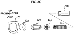
- a gaze-forward direction of the wearer when the helmet is attached the lens unit 100 is defined as the front, and the opposite direction thereto is defined as the rear.
- the left and right are defined as one direction and the opposite direction thereto out of lateral directions lying in the same plane as the gaze of the wearer.
- Upward and downward are defined as one direction and the opposite direction thereto out of directions orthogonal to the same plane as the front-rear and left-right directions.
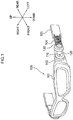
- Fig. 1 is a perspective view illustrating the overall lens unit and its attachment mechanism according to the present exemplary embodiment.
- the lens unit 100 according to the present exemplary embodiment includes the frame member 101 to support the lenses, and the side frame members 102 that each extend rearward, orthogonally to the left-right direction, from a left-right direction end portion of the frame member 101.
- the lens unit 100 further includes the angle adjustment arms 120 that each have the one end side axially supported together with the corresponding side frame member 102 by the first member 110, the ratchet stays 104 that each have the one end side axially supported together with the other end side of the corresponding angle adjustment arm 120 by the second member 130, and the ratchet stay holders 105 that each support the corresponding ratchet stay 104 so as to allow extension and retraction in the front-rear direction of the face of the helmet wearer.
- Each ratchet stay holder 105 is, for example, formed with a recess into which the corresponding ratchet stay 104 is inserted so as to be capable of extending and retracting.
- Adjustment of the angle of the lens unit 100 in the up-down direction of the face can be performed by tilting the lens unit 100 in the up-down direction of the face about the axis of the first member 110, by tilting the lens unit 100 in the up-down direction of the face about the axis of the second member 130, or by tilting the lens unit 100 in the up-down direction of the face about the axis of the first member 110 and the axis of the second member 130.
- Adjustment of the position of the lens unit 100 in the up-down direction of the face is achieved by moving the lens unit 100 in the up-down direction of the face about the axis of the second member 130, and then adjusting the angle about the axis of the first member 110.
- adjustment of the position of the lens unit 100 in the front-rear direction of the face can be performed by inserting each ratchet stay 104 into the corresponding ratchet stay holder 105 or pulling the ratchet stay 104 out from the ratchet stay holder 105.
- Fig. 1 explanation is given regarding the left side face of the lens unit 100.
- the right side face is configured similarly to the left side face.
- Fig. 1 illustrates a specific example in which a left-right direction outer side face of the side frame member 102 and a left-right direction inner side face at the one end side of the angle adjustment arm 120 are superimposed on each other, and a left-right direction outer side face at the other end side of the angle adjustment arm 120 and a left-right direction inner side face at the one end side of the ratchet stay 104 are superimposed on each other.
- either face of the side frame member 102 and either face of the angle adjustment arm 120 may be superimposed on each other, and either face of the angle adjustment arm 120 and either face of the ratchet stay 104 may be superimposed on each other, as desired.
- Fig. 2A is a side view from the left, illustrating relevant portions of the lens unit and its attachment mechanism according to the present exemplary embodiment.
- Fig. 2B is a side view from the left, illustrating relevant portions of the lens unit and its attachment mechanism according to the present exemplary embodiment, and is an explanatory diagram for a case in which the up-down direction position of the lens unit is adjusted using the second member.
- Fig. 2C is a side view from the left, illustrating relevant portions of the lens unit and its attachment mechanism according to the present exemplary embodiment, and is an explanatory diagram for a case in which the up-down direction angle of the lens unit is adjusted using the first member.
- the side frame member 102 and the one end side of the angle adjustment arm 120 are axially supported by the first member 110 such that the side frame member 102 and the angle adjustment arm 120 pivot with respect to each other as viewed along the left-right direction.
- the other end side of the angle adjustment arm 120 and the one end side of the ratchet stay 104 are axially supported by the second member 130 such that the angle adjustment arm 120 and the ratchet stay 104 pivot with respect to each other as viewed along the left-right direction.
- the ratchet stay 104 is inserted into the ratchet stay holder 105, formed in a hollow shape, for example, in the direction of the arrow A in Fig. 2A .
- the ratchet stay 104 is configured so as to be capable of extending and retracting in both directions with respect to the ratchet stay holder 105, as indicated by the bidirectional arrow B.
- the angle adjustment arm 120 is inclined in the upward direction with respect to the face of the wearer around the second member 130, such that the lens unit 100 coupled to the one end side of the angle adjustment arm 120 is moved to an upward direction position of the face. Note that positional movement in the downward direction of the face is also possible, as indicated by the bidirectional arrow C.
- the angle adjustment arm 120 is inclined in the downward direction with respect to the face around the second member 130, and the lens unit 100 is inclined in the upward direction of the face about the first member 110, such that the lens unit 100 approaches the face, and the angle thereof is adjusted in the upward direction.
- the angle may also be adjusted in the downward direction of the face, as indicated by the bidirectional arrow D.
- the angle adjustment arm 120 can be inclined around the second member 130 to move the lens unit 100 in the up-down direction of the face while the side frame member 102 of the lens unit 100 and the angle adjustment arm 120 are maintained in a parallel state.
- Fig. 2A to Fig. 2C illustrate the left side face of the lens unit 100.
- the right side face is configured similarly to the left side face.
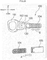
- Fig. 3A is a plan view illustrating relevant portions of the lens unit and its attachment mechanism according to the present exemplary embodiment
- Fig. 3B is a front view illustrating relevant portions of the lens unit and its attachment mechanism according to the present exemplary embodiment
- Fig. 3C is a side view from the left illustrating relevant portions of the lens unit and its attachment mechanism according to the present exemplary embodiment.
- the side frame member 102 on the left side of the lens unit 100 and the one end side of the angle adjustment arm 120 are coupled together.
- the other end side of the angle adjustment arm 120 and the one end side of the ratchet stay 104 are coupled together through a size adjustment washer 103, serving as an example of a size adjustment member.
- the other end side of the ratchet stay 104 is inserted into the hollow ratchet stay holder 105.
- the size adjustment washer 103 adjusts the distance between the side frame member 102 and the ratchet stay 104 according to a lateral width size of the face of the wearer wearing the lens unit 100.
- Fig. 3A, Fig. 3B , and Fig. 3C illustrate an example in which the size adjustment washer 103 is inserted between the angle adjustment arm 120 and the ratchet stay 104.
- the size adjustment washer 103 may be inserted between the side frame member 102 and the angle adjustment arm 120, or may be inserted both between the side frame member 102 and the angle adjustment arm 120 and between the angle adjustment arm 120 and the ratchet stay 104.
- Fig. 3A, Fig. 3B , Fig. 3C illustrate the left side face of the lens unit 100. However, the right side face is configured similarly to the left side face.
- FIG. 4 is a plan view illustrating an example of attachment of size adjustment washers, serving as examples of the size adjustment member, and an example of attachment of a washer with an anti-slip function and an angle adjustment function, and serving as an example of the angle retention member, in the lens unit and its attachment mechanism according to the present exemplary embodiment.
- a method for adjusting the distance between the side frame member 102 and the ratchet stay 104 according to the lateral width size of the face of the wearer wearing the lens unit 100 is illustrated in FIG. 4 .
- the other end side of the angle adjustment arm 120 and the one end side of the ratchet stay 104 are coupled together through the size adjustment washer 103.
- the size adjustment washer 103 has a function of adjusting the distance between the side frame member 102 and the ratchet stay 104 according to the lateral width size of the face of a person wearing the lens unit 100.
- Fig. 4 illustrates examples of an S size, an M size, an L size, and an XL size corresponding to lateral width sizes of the face of the wearer of the lens unit 100. Obviously, however, there is no limitation to these sizes.
- the angle adjustment arm 120 may also be provided with a washer 106, serving as an example of an angle retention member with an anti-slip function for maintaining a specific angle after the angle of the lens unit adjusted. This enables the lens units 100 to use in various fields in which precision in the position (angle) of the lens unit 100 is demanded.
- Fig. 4 illustrates an example in which the washer 106 with an anti-slip function is inserted between the angle adjustment arm 120 and the ratchet stay 104.
- the washer 106 with an anti-slip function may be inserted between the side frame member 102 and the angle adjustment arm 120, or may be inserted both between the side frame member 102 and the angle adjustment arm 120 and between the angle adjustment arm 120 and the ratchet stay 104.
- Fig. 4 illustrates the left side face of the lens unit 100. However, the right side face is configured similarly to the left side face.
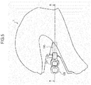
- FIG. 5 is a side view from the left illustrating an example in which the lens unit and its attachment mechanism according to the present exemplary embodiment are mounted to a helmet.
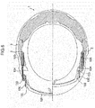
- Fig. 6 is a cross-section taken along A-A in Fig. 5 when the lens unit and its attachment mechanism according to the present exemplary embodiment are mounted to a helmet.
- each ratchet stay holder 105 is attached to a recess 3 formed at a location close to the head of the wearer at an inner side of a helmet 1.
- Fig. 6 illustrates an example in which the ratchet stay holders 105 are mounted in recesses 3 formed in a mask liner 2 fixed to the inner side of the helmet 1.
- the recesses 3 may be provided to any location fixed to the inner side of the helmet.
- the angle formed between the side frame member 102 and the angle adjustment arm 120, and the angle formed between the angle adjustment arm 120 and the ratchet stay 104 are changed to enable the position of the lens unit 100 to be adjusted over a wide range.
- the position and incline of the lens unit 100 in the up-down direction can be varied by using the fulcrum points axially supported at plural locations. Accordingly, the advantageous effect of being able to adjust the position of the lens unit 100 precisely and flexibly so as to better fit the wearer can be obtained, unlike in the related technology.
- the present invention may also be applied to technology in which various information, such as numerical data on instruments required for driving or information relating to a field of view to the rear, is displayed in a predetermined region of a lens of spectacles worn by a rider wearing a helmet.
- the lens unit is employed as a video display device.
- Such information needs to be suitably displayed in a visible position, such that it does not obstruct the field of view of the driver when driving. Therefore, slippage of the position of the spectacles during driving could have serious safety implications.
- the lens unit and its attachment mechanism of the present invention are provided to a rider wearing a helmet, such that the lens unit is adjusted to the position (angle) that best fits the rider. Accordingly, slippage of the lens unit during driving does not occur. Accordingly, various information can be displayed at an appropriate position on the lens unit, and the field of view of the rider can be well secured, enabling the advantageous effect of adequately securing safety to be obtained.
- the present invention relates to an attachment mechanism to attach a lens unit to a helmet.
- the side frame member 102 extending rearward from the left-right direction end portion of the frame member 101, which supports the lenses of the lens unit 100, has one face running substantially parallel to the front-rear direction.
- the one face and the opposing face, running substantially parallel to the front-rear direction at the one end side of the angle adjustment arm 120, which adjusts the angles of elevation and depression of the lenses, are superimposed on each other.
- the first member 110 axially supports the side frame member 102 and the angle adjustment arm 120 so as to allow pivoting with respect to each other.
- the angle adjustment arm 120 has one face running substantially parallel to the front-rear direction at the other end side of the angle adjustment arm 120.
- the one face and the opposing face, running substantially parallel to the front-rear direction at the one end side of the ratchet stay 104 that adjusts the front-rear direction position of the lenses, are superimposed on each other.
- the second member 130 axially supports the angle adjustment arm 120 and the ratchet stay 104 so as to allow pivoting with respect to each other.
- the ratchet stay holder 105 that retains the other end side of the ratchet stay 104 so as to allow extending and retracting in the front-rear direction is also included.
- a lens unit attachment mechanism is thereby obtained that is capable of securing the field of view of spectacles by adapting to the length of the face and positions of the eyes of various spectacle wearers, and is also capable of obtaining a good fitting sensation of the spectacles by performing fine adjustment of positions and angles.
Landscapes
- Physics & Mathematics (AREA)
- Health & Medical Sciences (AREA)
- General Physics & Mathematics (AREA)
- Optics & Photonics (AREA)
- Ophthalmology & Optometry (AREA)
- Vascular Medicine (AREA)
- Biomedical Technology (AREA)
- Heart & Thoracic Surgery (AREA)
- Engineering & Computer Science (AREA)
- Life Sciences & Earth Sciences (AREA)
- Animal Behavior & Ethology (AREA)
- General Health & Medical Sciences (AREA)
- Public Health (AREA)
- Veterinary Medicine (AREA)
- Eyeglasses (AREA)
- Helmets And Other Head Coverings (AREA)
Applications Claiming Priority (2)
| Application Number | Priority Date | Filing Date | Title |
|---|---|---|---|
| JP2016114206A JP6617078B2 (ja) | 2016-06-08 | 2016-06-08 | レンズ体の取付機構 |
| PCT/JP2017/014252 WO2017212767A1 (ja) | 2016-06-08 | 2017-04-05 | レンズ体の取付機構 |
Publications (3)
| Publication Number | Publication Date |
|---|---|
| EP3469940A1 EP3469940A1 (en) | 2019-04-17 |
| EP3469940A4 EP3469940A4 (en) | 2020-01-01 |
| EP3469940B1 true EP3469940B1 (en) | 2021-02-24 |
Family
ID=60578574
Family Applications (1)
| Application Number | Title | Priority Date | Filing Date |
|---|---|---|---|
| EP17809950.3A Active EP3469940B1 (en) | 2016-06-08 | 2017-04-05 | Lens body mounting mechanism |
Country Status (4)
| Country | Link |
|---|---|
| US (1) | US10772374B2 (enExample) |
| EP (1) | EP3469940B1 (enExample) |
| JP (1) | JP6617078B2 (enExample) |
| WO (1) | WO2017212767A1 (enExample) |
Families Citing this family (13)
| Publication number | Priority date | Publication date | Assignee | Title |
|---|---|---|---|---|
| JP6568887B2 (ja) * | 2017-03-14 | 2019-08-28 | 本田技研工業株式会社 | 情報表示装置 |
| US10959478B2 (en) * | 2017-09-22 | 2021-03-30 | Hummingbird Sports, Llc | Eye protection orientation system |
| US20200159027A1 (en) * | 2018-11-20 | 2020-05-21 | Facebook Technologies, Llc | Head-mounted display with unobstructed peripheral viewing |
| DE102019101083B3 (de) * | 2019-01-16 | 2020-07-09 | Pfanner Schutzbekleidung Gmbh | Vorrichtung zum Haltern eines Brillenbügelvorderteils |
| CN109782449A (zh) * | 2019-03-27 | 2019-05-21 | 深圳市忻毅科技有限公司 | 一种可前后调节的智能眼镜 |
| CN109828374B (zh) * | 2019-03-27 | 2024-12-27 | 何毅 | 一种左右调节的智能眼镜 |
| US11213089B2 (en) * | 2019-06-04 | 2022-01-04 | Msa Technology, Llc | Protective helmet with face protection shield and linkage mechanism |
| JP2021058544A (ja) * | 2019-10-10 | 2021-04-15 | 株式会社谷沢製作所 | 眼保護具 |
| EP4195969A4 (en) | 2020-08-17 | 2024-12-25 | Milwaukee Electric Tool Corporation | HAT AND SUN VISOR ATTACHMENT SYSTEM |
| AU2021328844A1 (en) | 2020-08-17 | 2023-03-09 | Milwaukee Electric Tool Corporation | Safety headwear and accessories |
| CN112612140B (zh) * | 2020-12-29 | 2022-10-18 | 重庆蓝岸科技股份有限公司 | 一种无声双向棘轮结构 |
| CA3206224A1 (en) | 2021-02-08 | 2022-08-11 | Todd Andrew Zeilinger | Hard hat face shield attachment system |
| AU2022232312A1 (en) | 2021-03-12 | 2023-08-24 | Milwaukee Electric Tool Corporation | Safety headwear systems and accessories |
Family Cites Families (18)
| Publication number | Priority date | Publication date | Assignee | Title |
|---|---|---|---|---|
| US4544245A (en) | 1979-07-16 | 1985-10-01 | Mckesson Corporation | Adjustable safety spectacle |
| JPH0312218U (enExample) * | 1989-06-21 | 1991-02-07 | ||
| US5052054A (en) * | 1990-01-02 | 1991-10-01 | Birum Donald A | Cap structure with implement adapter |
| JPH04127221A (ja) | 1990-09-18 | 1992-04-28 | Toshiba Corp | マウス装置 |
| JPH04127221U (ja) | 1991-05-09 | 1992-11-19 | 株式会社アライヘルメツト | ヘルメツト |
| US5230101A (en) * | 1991-09-27 | 1993-07-27 | Gentex Corporation | Dual visor operating mechanism |
| JPH07279939A (ja) * | 1994-04-07 | 1995-10-27 | Asahi Glass Co Ltd | ワッシャー |
| JPH11346336A (ja) * | 1998-06-01 | 1999-12-14 | Fuji Electric Co Ltd | 眼鏡型ヘッドマウントディスプレイ |
| JP2000178820A (ja) | 1998-12-11 | 2000-06-27 | Wise Gear:Kk | ヘルメット |
| JP2000303244A (ja) * | 1999-04-23 | 2000-10-31 | Tanizawa Seisakusho Ltd | ヘルメットの内装体取付具 |
| US6595635B2 (en) * | 2001-10-12 | 2003-07-22 | Mageyes, Inc. | Apparatus for positioning a magnifying lens |
| JP2005061449A (ja) * | 2003-08-18 | 2005-03-10 | Shibao Tsukada | ボルトとナットから成る締結具 |
| US6892393B1 (en) * | 2003-12-29 | 2005-05-17 | Jack Provost | Safety helmet attachment and method for shielding eyes |
| JP2005309272A (ja) * | 2004-04-26 | 2005-11-04 | Hiroshi Nakazawa | 傾斜角自在形眼鏡 |
| WO2008025083A1 (en) * | 2006-08-31 | 2008-03-06 | David John Springer | Hard hat with attached safety glasses |
| FR2938738B1 (fr) * | 2008-11-25 | 2011-01-14 | Thales Sa | Casque comportant une visiere mobile avec un axe de rotation vertical. |
| GB2504323B (en) * | 2012-07-25 | 2015-10-14 | Andrew Greene | A modified helmet |
| DE102013017830A1 (de) * | 2013-10-24 | 2015-04-30 | Pfanner Schutzbekleidung Gmbh | Schutzbrille zur Anbringung an einem Schutzhelm und mit der Schutzbrille ausgestatteter Schutzhelm |
-
2016
- 2016-06-08 JP JP2016114206A patent/JP6617078B2/ja active Active
-
2017
- 2017-04-05 EP EP17809950.3A patent/EP3469940B1/en active Active
- 2017-04-05 WO PCT/JP2017/014252 patent/WO2017212767A1/ja not_active Ceased
- 2017-04-05 US US16/306,915 patent/US10772374B2/en active Active
Non-Patent Citations (1)
| Title |
|---|
| None * |
Also Published As
| Publication number | Publication date |
|---|---|
| EP3469940A1 (en) | 2019-04-17 |
| JP2017218696A (ja) | 2017-12-14 |
| WO2017212767A1 (ja) | 2017-12-14 |
| JP6617078B2 (ja) | 2019-12-04 |
| EP3469940A4 (en) | 2020-01-01 |
| US20190133236A1 (en) | 2019-05-09 |
| US10772374B2 (en) | 2020-09-15 |
Similar Documents
| Publication | Publication Date | Title |
|---|---|---|
| EP3469940B1 (en) | Lens body mounting mechanism | |
| CN1227557C (zh) | 眼镜保持装置 | |
| WO2014201472A1 (en) | Eyewear configured to support computing device(s) | |
| EP3812828A1 (en) | Moving body video projection system, video projection device, video display light diffraction optical element, helmet, and video projection method | |
| US20220244549A1 (en) | Attachment and head-mounted display | |
| WO2007148650A1 (ja) | 眼鏡セット | |
| WO2009004618A2 (en) | Optical system for enhanced vision | |
| EP3599498B1 (en) | Spectacle frame and temple thereof | |
| JP6076121B2 (ja) | 眼鏡フレーム | |
| EP3375311B1 (en) | Information display assembly | |
| JP7233090B2 (ja) | 双眼ルーペ | |
| CN117647899A (zh) | 构造成用于向前看和向后看的眼镜镜片件 | |
| JP6407793B2 (ja) | 頭部装着表示装置 | |
| JP4039905B2 (ja) | ルーペ取付用眼鏡フレーム及びこの眼鏡フレームを用いたルーペ | |
| JP3210521U (ja) | 明視用付加メガネ | |
| JP3114698U (ja) | 眼鏡 | |
| JP3541198B1 (ja) | 眼鏡用防塵具 | |
| JP7712009B1 (ja) | 医療用の双眼ルーペ装置 | |
| JP2016151752A (ja) | 眼鏡 | |
| US20230375855A1 (en) | Corrective Lens Apparatus and Method | |
| JP2000224519A (ja) | 頭部装着型表示装置およびホルダ | |
| US20200249485A1 (en) | Image display system | |
| AU2021274269B9 (en) | Line-of-sight detecting device | |
| CN211506030U (zh) | 可调节支架装置和潜水头盔 | |
| JP3115758U (ja) | 眼鏡のズレ止め具 |
Legal Events
| Date | Code | Title | Description |
|---|---|---|---|
| STAA | Information on the status of an ep patent application or granted ep patent |
Free format text: STATUS: THE INTERNATIONAL PUBLICATION HAS BEEN MADE |
|
| PUAI | Public reference made under article 153(3) epc to a published international application that has entered the european phase |
Free format text: ORIGINAL CODE: 0009012 |
|
| STAA | Information on the status of an ep patent application or granted ep patent |
Free format text: STATUS: REQUEST FOR EXAMINATION WAS MADE |
|
| 17P | Request for examination filed |
Effective date: 20181206 |
|
| AK | Designated contracting states |
Kind code of ref document: A1 Designated state(s): AL AT BE BG CH CY CZ DE DK EE ES FI FR GB GR HR HU IE IS IT LI LT LU LV MC MK MT NL NO PL PT RO RS SE SI SK SM TR |
|
| AX | Request for extension of the european patent |
Extension state: BA ME |
|
| RAP1 | Party data changed (applicant data changed or rights of an application transferred) |
Owner name: SHOEI CO., LTD. |
|
| DAV | Request for validation of the european patent (deleted) | ||
| DAX | Request for extension of the european patent (deleted) | ||
| REG | Reference to a national code |
Ref country code: DE Ref legal event code: R079 Ref document number: 602017033435 Country of ref document: DE Free format text: PREVIOUS MAIN CLASS: A42B0003040000 Ipc: A42B0003180000 |
|
| A4 | Supplementary search report drawn up and despatched |
Effective date: 20191204 |
|
| RIC1 | Information provided on ipc code assigned before grant |
Ipc: A42B 3/18 20060101AFI20191128BHEP Ipc: G02C 5/20 20060101ALI20191128BHEP Ipc: G02C 3/00 20060101ALI20191128BHEP Ipc: A61F 9/02 20060101ALI20191128BHEP |
|
| GRAP | Despatch of communication of intention to grant a patent |
Free format text: ORIGINAL CODE: EPIDOSNIGR1 |
|
| STAA | Information on the status of an ep patent application or granted ep patent |
Free format text: STATUS: GRANT OF PATENT IS INTENDED |
|
| INTG | Intention to grant announced |
Effective date: 20200914 |
|
| GRAS | Grant fee paid |
Free format text: ORIGINAL CODE: EPIDOSNIGR3 |
|
| GRAA | (expected) grant |
Free format text: ORIGINAL CODE: 0009210 |
|
| STAA | Information on the status of an ep patent application or granted ep patent |
Free format text: STATUS: THE PATENT HAS BEEN GRANTED |
|
| AK | Designated contracting states |
Kind code of ref document: B1 Designated state(s): AL AT BE BG CH CY CZ DE DK EE ES FI FR GB GR HR HU IE IS IT LI LT LU LV MC MK MT NL NO PL PT RO RS SE SI SK SM TR |
|
| REG | Reference to a national code |
Ref country code: CH Ref legal event code: EP |
|
| REG | Reference to a national code |
Ref country code: AT Ref legal event code: REF Ref document number: 1363368 Country of ref document: AT Kind code of ref document: T Effective date: 20210315 |
|
| REG | Reference to a national code |
Ref country code: IE Ref legal event code: FG4D |
|
| REG | Reference to a national code |
Ref country code: DE Ref legal event code: R096 Ref document number: 602017033435 Country of ref document: DE |
|
| REG | Reference to a national code |
Ref country code: LT Ref legal event code: MG9D |
|
| REG | Reference to a national code |
Ref country code: NL Ref legal event code: MP Effective date: 20210224 |
|
| PG25 | Lapsed in a contracting state [announced via postgrant information from national office to epo] |
Ref country code: LT Free format text: LAPSE BECAUSE OF FAILURE TO SUBMIT A TRANSLATION OF THE DESCRIPTION OR TO PAY THE FEE WITHIN THE PRESCRIBED TIME-LIMIT Effective date: 20210224 Ref country code: BG Free format text: LAPSE BECAUSE OF FAILURE TO SUBMIT A TRANSLATION OF THE DESCRIPTION OR TO PAY THE FEE WITHIN THE PRESCRIBED TIME-LIMIT Effective date: 20210524 Ref country code: PT Free format text: LAPSE BECAUSE OF FAILURE TO SUBMIT A TRANSLATION OF THE DESCRIPTION OR TO PAY THE FEE WITHIN THE PRESCRIBED TIME-LIMIT Effective date: 20210624 Ref country code: NO Free format text: LAPSE BECAUSE OF FAILURE TO SUBMIT A TRANSLATION OF THE DESCRIPTION OR TO PAY THE FEE WITHIN THE PRESCRIBED TIME-LIMIT Effective date: 20210524 Ref country code: HR Free format text: LAPSE BECAUSE OF FAILURE TO SUBMIT A TRANSLATION OF THE DESCRIPTION OR TO PAY THE FEE WITHIN THE PRESCRIBED TIME-LIMIT Effective date: 20210224 Ref country code: FI Free format text: LAPSE BECAUSE OF FAILURE TO SUBMIT A TRANSLATION OF THE DESCRIPTION OR TO PAY THE FEE WITHIN THE PRESCRIBED TIME-LIMIT Effective date: 20210224 Ref country code: GR Free format text: LAPSE BECAUSE OF FAILURE TO SUBMIT A TRANSLATION OF THE DESCRIPTION OR TO PAY THE FEE WITHIN THE PRESCRIBED TIME-LIMIT Effective date: 20210525 |
|
| REG | Reference to a national code |
Ref country code: AT Ref legal event code: MK05 Ref document number: 1363368 Country of ref document: AT Kind code of ref document: T Effective date: 20210224 |
|
| PG25 | Lapsed in a contracting state [announced via postgrant information from national office to epo] |
Ref country code: RS Free format text: LAPSE BECAUSE OF FAILURE TO SUBMIT A TRANSLATION OF THE DESCRIPTION OR TO PAY THE FEE WITHIN THE PRESCRIBED TIME-LIMIT Effective date: 20210224 Ref country code: PL Free format text: LAPSE BECAUSE OF FAILURE TO SUBMIT A TRANSLATION OF THE DESCRIPTION OR TO PAY THE FEE WITHIN THE PRESCRIBED TIME-LIMIT Effective date: 20210224 Ref country code: LV Free format text: LAPSE BECAUSE OF FAILURE TO SUBMIT A TRANSLATION OF THE DESCRIPTION OR TO PAY THE FEE WITHIN THE PRESCRIBED TIME-LIMIT Effective date: 20210224 Ref country code: NL Free format text: LAPSE BECAUSE OF FAILURE TO SUBMIT A TRANSLATION OF THE DESCRIPTION OR TO PAY THE FEE WITHIN THE PRESCRIBED TIME-LIMIT Effective date: 20210224 Ref country code: SE Free format text: LAPSE BECAUSE OF FAILURE TO SUBMIT A TRANSLATION OF THE DESCRIPTION OR TO PAY THE FEE WITHIN THE PRESCRIBED TIME-LIMIT Effective date: 20210224 |
|
| PG25 | Lapsed in a contracting state [announced via postgrant information from national office to epo] |
Ref country code: IS Free format text: LAPSE BECAUSE OF FAILURE TO SUBMIT A TRANSLATION OF THE DESCRIPTION OR TO PAY THE FEE WITHIN THE PRESCRIBED TIME-LIMIT Effective date: 20210624 |
|
| PG25 | Lapsed in a contracting state [announced via postgrant information from national office to epo] |
Ref country code: EE Free format text: LAPSE BECAUSE OF FAILURE TO SUBMIT A TRANSLATION OF THE DESCRIPTION OR TO PAY THE FEE WITHIN THE PRESCRIBED TIME-LIMIT Effective date: 20210224 Ref country code: CZ Free format text: LAPSE BECAUSE OF FAILURE TO SUBMIT A TRANSLATION OF THE DESCRIPTION OR TO PAY THE FEE WITHIN THE PRESCRIBED TIME-LIMIT Effective date: 20210224 Ref country code: AT Free format text: LAPSE BECAUSE OF FAILURE TO SUBMIT A TRANSLATION OF THE DESCRIPTION OR TO PAY THE FEE WITHIN THE PRESCRIBED TIME-LIMIT Effective date: 20210224 Ref country code: SM Free format text: LAPSE BECAUSE OF FAILURE TO SUBMIT A TRANSLATION OF THE DESCRIPTION OR TO PAY THE FEE WITHIN THE PRESCRIBED TIME-LIMIT Effective date: 20210224 |
|
| REG | Reference to a national code |
Ref country code: DE Ref legal event code: R097 Ref document number: 602017033435 Country of ref document: DE |
|
| PG25 | Lapsed in a contracting state [announced via postgrant information from national office to epo] |
Ref country code: MC Free format text: LAPSE BECAUSE OF FAILURE TO SUBMIT A TRANSLATION OF THE DESCRIPTION OR TO PAY THE FEE WITHIN THE PRESCRIBED TIME-LIMIT Effective date: 20210224 Ref country code: RO Free format text: LAPSE BECAUSE OF FAILURE TO SUBMIT A TRANSLATION OF THE DESCRIPTION OR TO PAY THE FEE WITHIN THE PRESCRIBED TIME-LIMIT Effective date: 20210224 Ref country code: DK Free format text: LAPSE BECAUSE OF FAILURE TO SUBMIT A TRANSLATION OF THE DESCRIPTION OR TO PAY THE FEE WITHIN THE PRESCRIBED TIME-LIMIT Effective date: 20210224 Ref country code: SK Free format text: LAPSE BECAUSE OF FAILURE TO SUBMIT A TRANSLATION OF THE DESCRIPTION OR TO PAY THE FEE WITHIN THE PRESCRIBED TIME-LIMIT Effective date: 20210224 |
|
| PG25 | Lapsed in a contracting state [announced via postgrant information from national office to epo] |
Ref country code: LU Free format text: LAPSE BECAUSE OF NON-PAYMENT OF DUE FEES Effective date: 20210405 |
|
| PLBE | No opposition filed within time limit |
Free format text: ORIGINAL CODE: 0009261 |
|
| STAA | Information on the status of an ep patent application or granted ep patent |
Free format text: STATUS: NO OPPOSITION FILED WITHIN TIME LIMIT |
|
| REG | Reference to a national code |
Ref country code: BE Ref legal event code: MM Effective date: 20210430 |
|
| PG25 | Lapsed in a contracting state [announced via postgrant information from national office to epo] |
Ref country code: AL Free format text: LAPSE BECAUSE OF FAILURE TO SUBMIT A TRANSLATION OF THE DESCRIPTION OR TO PAY THE FEE WITHIN THE PRESCRIBED TIME-LIMIT Effective date: 20210224 Ref country code: CH Free format text: LAPSE BECAUSE OF NON-PAYMENT OF DUE FEES Effective date: 20210430 Ref country code: LI Free format text: LAPSE BECAUSE OF NON-PAYMENT OF DUE FEES Effective date: 20210430 Ref country code: ES Free format text: LAPSE BECAUSE OF FAILURE TO SUBMIT A TRANSLATION OF THE DESCRIPTION OR TO PAY THE FEE WITHIN THE PRESCRIBED TIME-LIMIT Effective date: 20210224 |
|
| 26N | No opposition filed |
Effective date: 20211125 |
|
| PG25 | Lapsed in a contracting state [announced via postgrant information from national office to epo] |
Ref country code: SI Free format text: LAPSE BECAUSE OF FAILURE TO SUBMIT A TRANSLATION OF THE DESCRIPTION OR TO PAY THE FEE WITHIN THE PRESCRIBED TIME-LIMIT Effective date: 20210224 |
|
| PG25 | Lapsed in a contracting state [announced via postgrant information from national office to epo] |
Ref country code: IE Free format text: LAPSE BECAUSE OF NON-PAYMENT OF DUE FEES Effective date: 20210405 |
|
| PG25 | Lapsed in a contracting state [announced via postgrant information from national office to epo] |
Ref country code: IS Free format text: LAPSE BECAUSE OF FAILURE TO SUBMIT A TRANSLATION OF THE DESCRIPTION OR TO PAY THE FEE WITHIN THE PRESCRIBED TIME-LIMIT Effective date: 20210624 |
|
| PG25 | Lapsed in a contracting state [announced via postgrant information from national office to epo] |
Ref country code: BE Free format text: LAPSE BECAUSE OF NON-PAYMENT OF DUE FEES Effective date: 20210430 |
|
| PG25 | Lapsed in a contracting state [announced via postgrant information from national office to epo] |
Ref country code: CY Free format text: LAPSE BECAUSE OF FAILURE TO SUBMIT A TRANSLATION OF THE DESCRIPTION OR TO PAY THE FEE WITHIN THE PRESCRIBED TIME-LIMIT Effective date: 20210224 |
|
| PG25 | Lapsed in a contracting state [announced via postgrant information from national office to epo] |
Ref country code: HU Free format text: LAPSE BECAUSE OF FAILURE TO SUBMIT A TRANSLATION OF THE DESCRIPTION OR TO PAY THE FEE WITHIN THE PRESCRIBED TIME-LIMIT; INVALID AB INITIO Effective date: 20170405 |
|
| PG25 | Lapsed in a contracting state [announced via postgrant information from national office to epo] |
Ref country code: MK Free format text: LAPSE BECAUSE OF FAILURE TO SUBMIT A TRANSLATION OF THE DESCRIPTION OR TO PAY THE FEE WITHIN THE PRESCRIBED TIME-LIMIT Effective date: 20210224 |
|
| PG25 | Lapsed in a contracting state [announced via postgrant information from national office to epo] |
Ref country code: MT Free format text: LAPSE BECAUSE OF FAILURE TO SUBMIT A TRANSLATION OF THE DESCRIPTION OR TO PAY THE FEE WITHIN THE PRESCRIBED TIME-LIMIT Effective date: 20210224 |
|
| PGFP | Annual fee paid to national office [announced via postgrant information from national office to epo] |
Ref country code: DE Payment date: 20250422 Year of fee payment: 9 |
|
| PGFP | Annual fee paid to national office [announced via postgrant information from national office to epo] |
Ref country code: GB Payment date: 20250423 Year of fee payment: 9 |
|
| PGFP | Annual fee paid to national office [announced via postgrant information from national office to epo] |
Ref country code: IT Payment date: 20250424 Year of fee payment: 9 |
|
| PGFP | Annual fee paid to national office [announced via postgrant information from national office to epo] |
Ref country code: FR Payment date: 20250425 Year of fee payment: 9 |