EP3468897B1 - Leckschutzfolie für einen fluidtank - Google Patents
Leckschutzfolie für einen fluidtank Download PDFInfo
- Publication number
- EP3468897B1 EP3468897B1 EP17719990.8A EP17719990A EP3468897B1 EP 3468897 B1 EP3468897 B1 EP 3468897B1 EP 17719990 A EP17719990 A EP 17719990A EP 3468897 B1 EP3468897 B1 EP 3468897B1
- Authority
- EP
- European Patent Office
- Prior art keywords
- sheet
- tank
- ribs
- film
- knobs
- Prior art date
- Legal status (The legal status is an assumption and is not a legal conclusion. Google has not performed a legal analysis and makes no representation as to the accuracy of the status listed.)
- Active
Links
Images

Classifications
-
- B—PERFORMING OPERATIONS; TRANSPORTING
- B65—CONVEYING; PACKING; STORING; HANDLING THIN OR FILAMENTARY MATERIAL
- B65D—CONTAINERS FOR STORAGE OR TRANSPORT OF ARTICLES OR MATERIALS, e.g. BAGS, BARRELS, BOTTLES, BOXES, CANS, CARTONS, CRATES, DRUMS, JARS, TANKS, HOPPERS, FORWARDING CONTAINERS; ACCESSORIES, CLOSURES, OR FITTINGS THEREFOR; PACKAGING ELEMENTS; PACKAGES
- B65D90/00—Component parts, details or accessories for large containers
- B65D90/02—Wall construction
- B65D90/04—Linings
-
- B—PERFORMING OPERATIONS; TRANSPORTING
- B65—CONVEYING; PACKING; STORING; HANDLING THIN OR FILAMENTARY MATERIAL
- B65D—CONTAINERS FOR STORAGE OR TRANSPORT OF ARTICLES OR MATERIALS, e.g. BAGS, BARRELS, BOTTLES, BOXES, CANS, CARTONS, CRATES, DRUMS, JARS, TANKS, HOPPERS, FORWARDING CONTAINERS; ACCESSORIES, CLOSURES, OR FITTINGS THEREFOR; PACKAGING ELEMENTS; PACKAGES
- B65D90/00—Component parts, details or accessories for large containers
- B65D90/02—Wall construction
- B65D90/04—Linings
- B65D90/046—Flexible liners, e.g. loosely positioned in the container
-
- B—PERFORMING OPERATIONS; TRANSPORTING
- B65—CONVEYING; PACKING; STORING; HANDLING THIN OR FILAMENTARY MATERIAL
- B65D—CONTAINERS FOR STORAGE OR TRANSPORT OF ARTICLES OR MATERIALS, e.g. BAGS, BARRELS, BOTTLES, BOXES, CANS, CARTONS, CRATES, DRUMS, JARS, TANKS, HOPPERS, FORWARDING CONTAINERS; ACCESSORIES, CLOSURES, OR FITTINGS THEREFOR; PACKAGING ELEMENTS; PACKAGES
- B65D90/00—Component parts, details or accessories for large containers
- B65D90/22—Safety features
- B65D90/24—Spillage-retaining means, e.g. recovery ponds
-
- B—PERFORMING OPERATIONS; TRANSPORTING
- B65—CONVEYING; PACKING; STORING; HANDLING THIN OR FILAMENTARY MATERIAL
- B65D—CONTAINERS FOR STORAGE OR TRANSPORT OF ARTICLES OR MATERIALS, e.g. BAGS, BARRELS, BOTTLES, BOXES, CANS, CARTONS, CRATES, DRUMS, JARS, TANKS, HOPPERS, FORWARDING CONTAINERS; ACCESSORIES, CLOSURES, OR FITTINGS THEREFOR; PACKAGING ELEMENTS; PACKAGES
- B65D90/00—Component parts, details or accessories for large containers
- B65D90/22—Safety features
- B65D90/46—Arrangements for carrying off, or preventing the formation of electrostatic charges
-
- B—PERFORMING OPERATIONS; TRANSPORTING
- B65—CONVEYING; PACKING; STORING; HANDLING THIN OR FILAMENTARY MATERIAL
- B65D—CONTAINERS FOR STORAGE OR TRANSPORT OF ARTICLES OR MATERIALS, e.g. BAGS, BARRELS, BOTTLES, BOXES, CANS, CARTONS, CRATES, DRUMS, JARS, TANKS, HOPPERS, FORWARDING CONTAINERS; ACCESSORIES, CLOSURES, OR FITTINGS THEREFOR; PACKAGING ELEMENTS; PACKAGES
- B65D90/00—Component parts, details or accessories for large containers
- B65D90/48—Arrangements of indicating or measuring devices
- B65D90/50—Arrangements of indicating or measuring devices of leakage-indicating devices
-
- B—PERFORMING OPERATIONS; TRANSPORTING
- B65—CONVEYING; PACKING; STORING; HANDLING THIN OR FILAMENTARY MATERIAL
- B65D—CONTAINERS FOR STORAGE OR TRANSPORT OF ARTICLES OR MATERIALS, e.g. BAGS, BARRELS, BOTTLES, BOXES, CANS, CARTONS, CRATES, DRUMS, JARS, TANKS, HOPPERS, FORWARDING CONTAINERS; ACCESSORIES, CLOSURES, OR FITTINGS THEREFOR; PACKAGING ELEMENTS; PACKAGES
- B65D90/00—Component parts, details or accessories for large containers
- B65D90/48—Arrangements of indicating or measuring devices
- B65D90/50—Arrangements of indicating or measuring devices of leakage-indicating devices
- B65D90/501—Arrangements of indicating or measuring devices of leakage-indicating devices comprising hollow spaces within walls
-
- B—PERFORMING OPERATIONS; TRANSPORTING
- B65—CONVEYING; PACKING; STORING; HANDLING THIN OR FILAMENTARY MATERIAL
- B65D—CONTAINERS FOR STORAGE OR TRANSPORT OF ARTICLES OR MATERIALS, e.g. BAGS, BARRELS, BOTTLES, BOXES, CANS, CARTONS, CRATES, DRUMS, JARS, TANKS, HOPPERS, FORWARDING CONTAINERS; ACCESSORIES, CLOSURES, OR FITTINGS THEREFOR; PACKAGING ELEMENTS; PACKAGES
- B65D2590/00—Component parts, details or accessories for large containers
- B65D2590/02—Wall construction
- B65D2590/04—Linings
- B65D2590/043—Flexible liners
- B65D2590/046—Bladders
Definitions
- the present invention relates to a leak protection film for lining a fluid tank, which film is made from a flexible, airtight, fluid-resistant material and is adapted to the internal shape of the tank.
- Leakage protection films are generally used to repair leaky fluid tanks or to retrofit single-walled fluid tanks with a double-walled leakage protection system. In the latter case, the airtight, fluid-resistant film is kept spaced from the wall of the tank in order to create a cavity between the film and the tank wall.
- the cavity can be pressurized or underpressure during operation of the tank and monitored for pressure constancy by means of a pressure measuring device. An increase in the overpressure or a decrease in the overpressure detected by the pressure measuring device indicates a leak in the film and / or the tank wall.
- a studded film e.g. made of metal
- an airtight, fluid-resistant cover layer e.g. a glass fiber composite layer.
- the use of nubbed plastic composites or air-permeable nonwovens is known as the spacer layer;
- a variety of airtight, fluid-resistant materials or material composites are used as the top layer, which are often applied in multiple layers.
- a spacer layer must first be applied to the inner wall of the tank, for example in the manner described, or a flexible spacer layer must first be applied to the film and the film, pre-assembled in this way, must be introduced into and into the tank be inflated. This requires additional processing steps and, in the second case, the difficulty of searching for a sufficiently stable and yet flexible spacer layer, which is also to be connected to the film with sufficient durability.
- the aim of the invention is to provide a leak protection film for lining a fluid tank, with which the fluid tank can be lined in a simple process and is then suitable for using a double-wall leak protection monitoring system.
- Such a film is inexpensive, can also be produced with great flexibility and is very durable due to its simple structure.
- the knobs do not run the risk of becoming detached from the rest of the film due to their direct formation from film material. Nevertheless, a secure support of the film on the tank wall and thus the continuity of the cavity are ensured, so that the fluid tank becomes a double-walled tank by lining the leak protection film alone.
- the outside of the film has ribs formed directly from the film material, on which the knobs are formed. With the same compressive strength the film can the film material is made thinner in the troughs that form between the ribs, so that the film becomes much lighter and more flexible overall.
- the ribs in at least two mutually crossing groups are arranged parallel to one another, with a knob being formed at each crossing point, or the ribs are arranged in a honeycomb structure, with a knob being formed at each honeycomb corner point. Both embodiments of the ribs result in a uniformly high compressive strength of the entire film without reducing its flexibility.
- the honeycomb structure enables a particularly material-saving and mechanically particularly stable leak protection film.
- the film including the knobs, preferably has a total thickness of a few tenths of a millimeter to a few millimeters, particularly preferably between one and three millimeters. Films of such total thickness can be flexibly produced from a large number of materials and reduce the tank volume only slightly. Furthermore, films of such thickness are sufficient to form a double-walled tank for a leak protection monitoring system.
- the film has between 70% and 90% of its total thickness on a rib and between 50% and 70% of its total thickness in a trough lying between the ribs.
- knobs are at a mutual distance of a few tenths of a millimeter to a few millimeters, preferably between half a millimeter and about two millimeters. Even a thin, flexible film achieves a consistently high compressive strength. Adjacent knobs can have the same mutual spacing in all directions; for easier production of the film, however, the distances between knobs of the film which are adjacent in different directions are preferably of different sizes. Further This allows the film to be given different flexibility in different directions, especially if the knobs are formed by ribs at the intersection or corner points.
- the film is rough on its inside facing away from the knobs with a roughness depth between 20 ⁇ m and 200 ⁇ m, preferably about 100 ⁇ m.
- a rough inside is easier or more durable to be provided with an optional coating.
- the inside of the film is coated with an electrically conductive cover layer.
- a cover layer if properly grounded, promotes the dissipation of electrostatic charges and thereby reduces the risk of ignition, e.g. when assembly or maintenance personnel enter the tank.
- a large number of flexible natural or plastic materials can be considered as film material, which can be selected depending on the fluid to be taken up by the tank.
- the film material is a polyurethane.
- Polyurethane foils are resistant to petrol, diesel and mineral oil, very flexible, easy to process and durable.
- the film can be inserted into the fluid tank in a collapsed state and can be expanded therein. In this way, the fluid tank can be lined without the need for installation personnel inside the tank.
- FIG. 1 A fluid tank 1 is shown as it is used, for example, as an underground fuel storage container in petrol stations.
- the tank 1 has a tank wall 2 with, for example, the shape of a cuboid, a ball or (here :) a lying cylinder with cambered ends 3, 4 and an opening 5, via which the tank 1 is filled, emptied and / or, if necessary, even entered can.
- Usual installations such as level sensors, ventilation openings, reinforcing webs etc. of tank 1 are in Fig. 1 not shown for clarity.
- the tank 1 is designed to hold liquid or gaseous fuels or other frequently aggressive fluids Fig. 1 lined with a leak protection film 6.
- the film 6 is made of an airtight material that is resistant to the fluids to be absorbed.
- the film 6 - with the exception of the opening 6 - is completely adapted to the inner shape of the tank 1.
- the film 6 For lining a tank, for example when renovating or retrofitting, the film 6 is inserted, for example in a collapsed state, through the opening 5 into the interior of the tank and expanded therein. To expand, the film 6 is inflated inside the tank and / or the space between film 6 and tank wall 2 is evacuated according to a method known to the person skilled in the art. Assembly personnel are not required inside the tank. To insert the film 6 through the opening 5 of an existing one To allow tanks, the material of the film 6 is flexible. The more flexible the film 6, the easier it can be inserted through the opening 5 and expanded inside the tank, but the lower the mechanical strength of the film 6.
- the fluid tank 1 has according to Fig. 1 a continuous cavity 7 between the tank wall 2 and the film 6.
- the tank 1 is thus double-walled, so that a double-wall leak protection monitoring system can be set up if desired or necessary.
- the cavity 7 is put under vacuum (evacuated) or overpressure (pressurized) during operation of the tank 1 and monitored for pressure constancy by means of a pressure measuring device. If an increase in the negative pressure or a drop in the positive pressure is registered, a leak in the tank wall 2 and / or the film 6 is concluded therefrom.
- the film 6 has to according to a first embodiment not shown, on its outer side is to face the tank wall 2 S a knob 8, which are formed directly from the sheet material itself ( “in one piece”).
- the knobs 8 support the film 6 of the tank wall 2 when the tank 1 is fully lined. In this way, said continuous cavity 7 is formed between the tank wall 2 and the film 6 with the aid of the knobs 8.
- the film 6 has formed optional ribs 9 on its outside S a facing the tank wall 2.
- the knobs 8 are formed on the ribs 9, that is to say further from them, so that the film 6 is supported on the tank wall 2 exclusively by the knobs 8, not by the ribs 9, during operation of the tank 1. Between adjacent ribs 9 there are troughs 10 in which the film 6 has its smallest wall thickness w having.
- This smallest wall thickness w on a trough 10 lying between ribs 9 is - in the unloaded state of the film 6 - for example between 50% and 70% of the total thickness d of the film 6; in the area of one of the ribs 9, the wall thickness w 'of the film 6 can be, for example, between 70% and 90% of the total thickness d of the film 6.
- the ribs 9 can, for example, all be arranged parallel and / or interrupted parallel to one another - also in the form of waves or zigzags and thus parallel to one another piece by piece, if desired, in order to be more flexible, for example, at folding points of the collapsed film 6 or at edges in the tank wall 2.
- the ribs 9 in two groups G 1 , G 2 are each arranged parallel to one another, the ribs 9 of one group G 1 crossing those of the other group G 2 .
- a knob 8 is formed, standing out further from these.
- the ribs form 9 parallelograms - in the example the 2a and 2b Rhombuses - in other cases rectangles or squares, with troughs 10 in between and knobs 8 formed at the corner points.
- 3a and 3b The example of 3a and 3b is that the 2a and 2b Similar, but the mutually parallel ribs 9 are arranged in three intersecting groups G 1 , G 2 , G 3 , so that the ribs 9 form triangles - here almost equilateral triangles - with intermediate troughs 10.
- the knobs 8 are again formed at the corner points.
- the ribs 9 can form more than three groups G 1 , G 2 , ..., generally G i , and / or can cross one another in a different way, so that, for example, unlike in the examples shown, they do not form congruent troughs 10.
- Individual ribs 9 or a group G i of parallel ribs 9 could also be formed less strongly, ie less raised, or the ribs 9 could be arranged irregularly at all.
- the ribs 9 of the example of the 4a and 4b are arranged in a honeycomb structure.
- the average Fig. 4b the different wall thicknesses w or w 'of the film 6 in the region of a trough 10 or the ribs 9 can be seen.
- Other honeycomb-like structures for example a sequence of quadrangles and octagons or the like, are alternatively possible.
- the film 6 is made, for example, of a polyurethane or another flexible, airtight, fluid-resistant material. It can have a total thickness d - including the knobs 8 - of a few tenths of a millimeter to a few millimeters, preferably between one and three millimeters.
- the knobs 8 also have a mutual spacing a of a few tenths of a millimeter to a few millimeters, preferably between half and about two millimeters, the distances a between knobs 8 adjacent to one another in different directions being generally of different sizes due to their structuring .
- the cross section of the knobs 8 can be round or - as in the examples shown - oval, but can also have a different shape.
- the film 6 can be smooth or rough on its inside S i facing away from the knobs 8 and in the latter case has, for example, a roughness depth, ie a difference between the maximum and minimum surface heights, between 20 ⁇ m and 200 ⁇ m, preferably about 100 ⁇ m.
- the film 6 is further provided on its inside S i with an electrically conductive cover layer 11 ( Fig. 4b ), for example a metal foil, an electrical conductive paste or the like, coated.
Landscapes
- Engineering & Computer Science (AREA)
- Mechanical Engineering (AREA)
- Laminated Bodies (AREA)
- Filling Or Discharging Of Gas Storage Vessels (AREA)
Description
- Die vorliegende Erfindung betrifft eine Leckschutzfolie zum Auskleiden eines Fluidtanks, welche Folie aus einem flexiblen, luftdichten, fluid-resistenten Material gefertigt und an die Innenform des Tanks angepasst ist.
- Im Allgemeinen werden Leckschutzfolien zum Sanieren von undichten Fluidtanks oder zum Nachrüsten von einwandigen Fluidtanks mit einem Doppelwand-Leckschutzüberwachungssystem verwendet. Im letzteren Fall wird die luftdichte, fluid-resistente Folie von der Wandung des Tanks beabstandet gehalten, um zwischen Folie und Tankwandung einen Hohlraum zu erzeugen. Der Hohlraum kann im Betrieb des Tanks unter Unterdruck oder Überdruck gesetzt und mittels einer Druckmesseinrichtung auf Drucckonstanz überwacht werden. Ein von der Druckmesseinrichtung detektiertes Ansteigen des Überdrucks bzw. Abfallen des Überdrucks deutet auf ein Leck in der Folie und/oder der Tankwandung hin.
- Zu diesem Zweck ist es, z.B. aus der
EP 2 055 404 B1 , bekannt, auf die Tankwandung zunächst eine Noppenfolie, z.B. aus Metall, als Abstandshalteschicht aufzubringen, welche den gewünschten Hohlraum errichtet, und danach auf die Noppenfolie eine luftdichte, fluid-resistente Deckschicht, z.B. eine Glasfaserverbundschicht aufzutragen, aufzukleben bzw. aufzulaminieren. Als Abstandshalteschicht ist alternativ die Verwendung genoppter Kunststoffverbunde oder luftdurchlässiger Vliese bekannt; als Deckschicht sind mannigfaltige luftdichte, fluid-resistente Materialien bzw. Materialverbunde in Gebrauch, welche oft mehrlagig aufgetragen werden. - Um das zeitraubende und gefährliche Arbeiten beim Aufbringen der Tankauskleidung zu vereinfachen, wurde vorgeschlagen, bereits vorkonfektionierte, an die Innenform des auszukleidenden Fluidtanks angepasste, aufblasbare Leckschutzfolien in drucklosem Zustand in den Tank einzuführen und anschließend darin aufzublasen, siehe beispielsweise die
DE 11 47 089 B ,CA 943 884 A ,DE 33 20 687 A1 ,EP 2 390 085 A1 ,EP 2 690 036 A1 oderAT 515.803 B1 EP2055404A1 eine Noppenfolie. Wenn dabei ein Doppelwand-Leckschutzüberwachungssystem realisiert werden soll, muss entweder zunächst - z.B. in der beschriebenen Weise - eine Abstandshalteschicht an der Tankinnenwand angebracht werden, oder eine flexible Abstandshalteschicht zunächst auf die Folie aufgebracht und die auf diese Weise vorkonfektionierte Folie in den Tank eingeführt und darin aufgeblasen werden. Das erfordert zusätzliche Bearbeitungsschritte und im zweitgenannten Fall die Schwierigkeit, die Suche nach einer ausreichend stabilen und dennoch flexiblen Abstandshalteschicht, welche ferner mit der Folie ausreichend haltbar zu verbinden ist. - Die Erfindung setzt sich zum Ziel, eine Leckschutzfolie zum Auskleiden eines Fluidtanks zu schaffen, mit welcher der Fluidtank in einem einfachen Verfahren ausgekleidet werden kann und danach zur Verwendung eines Doppelwand-Leckschutzüberwachungssystem geeignet ist.
- Dieses Ziel wird gemäß der Erfindung mit einer Leckschutzfolie gemäß Anspruch 1 erreicht.
- Eine derartige Folie ist kostengünstig, auch in hoher Flexibilität herstellbar und aufgrund des einfachen Aufbaus sehr haltbar. Die Noppen laufen aufgrund ihrer direkten Ausformung aus Folienmaterial nicht Gefahr, sich vom Rest der Folie abzulösen. Dennoch sind eine sichere Abstützung der Folie an der Tankwandung und damit die Durchgängigkeit des Hohlraums sichergestellt, sodass der Fluidtank durch Auskleiden alleine mit der genannten Leckschutzfolie zum Doppelwandtank wird.
- Dabei hat die Folie an ihrer Außenseite direkt aus dem Folienmaterial ausgeformte Rippen, an welchen die Noppen ausgeformt sind. Bei gleicher Druckfestigkeit der Folie kann dadurch das Folienmaterial in zwischen den Rippen sich ausbildenden Mulden dünner ausgeführt werden, sodass die Folie in Summe wesentlich leichter und flexibler wird.
- Ferner sind entweder die Rippen in zumindest zwei einander kreuzenden Gruppen jeweils zueinander parallel angeordnet, wobei an jedem Kreuzungspunkt eine Noppe ausgeformt ist, oder sind die Rippen in Wabenstruktur angeordnet, wobei an jedem Wabeneckpunkt eine Noppe ausgeformt ist. Beide Ausführungsformen der Rippen bewirken eine gleichmäßig hohe Druckfestigkeit der gesamten Folie, ohne dabei ihre Flexibilität zu reduzieren. Die Wabenstruktur ermöglicht eine besonders materialsparende und dabei mechanisch besonders stabile Leckschutzfolie.
- Bevorzugt hat die Folie einschließlich der Noppen eine Gesamtdicke von einigen Zehntel Millimetern bis einigen Millimetern, besonders bevorzugt zwischen einem und drei Millimetern. Folien solcher Gesamtdicke sind aus einer Vielzahl von Materialien einfach flexibel herstellbar und reduzieren das Tankvolumen nur geringfügig. Ferner reichen bereits Folien solcher Dicke zur Ausbildung eines Doppelwandtanks für ein Leckschutzüberwachungssystem aus.
- Zur sicheren Ausbildung des durchgängigen Hohlraums mit der flexiblen Folie ist es günstig, wenn die Folie an einer Rippe zwischen 70% und 90% ihrer Gesamtdicke und in einer zwischen Rippen liegenden Mulde zwischen 50% bis 70 % ihrer Gesamtdicke hat.
- Besonders vorteilhaft ist es, wenn die Noppen einen gegenseitigen Abstand von einigen Zehntel Millimetern bis einigen Millimetern, bevorzugt zwischen einem halben und etwa zwei Millimetern, haben. Auch eine dünne, flexible Folie erzielt dadurch eine gleichmäßig hohe Druckfestigkeit. Dabei können benachbarte Noppen jeweils in alle Richtungen gleiche gegenseitige Abstände haben; zur einfacheren Herstellung der Folie sind jedoch bevorzugt die Abstände zwischen in verschiedenen Richtungen benachbarten Noppen der Folie unterschiedlich groß. Ferner kann dadurch der Folie in verschiedenen Richtungen unterschiedliche Flexibilität verliehen werden, insbesondere wenn die Noppen an Kreuzungs- bzw. Eckpunkten von Rippen ausgeformt sind.
- Gemäß einer weiteren bevorzugten Ausführungsform ist die Folie an ihrer den Noppen abgewandten Innenseite rau mit einer Rautiefe zwischen 20 µm und 200 µm, bevorzugt etwa 100 µm. Eine raue Innenseite ist einfacher bzw. haltbarer mit einer optionalen Beschichtung zu versehen.
- Besonders günstig ist es, wenn die Folie an ihrer Innenseite mit einer elektrisch leitfähigen Deckschicht beschichtet ist. Eine solche Deckschicht fördert, wenn sie ordnungsgemäß geerdet ist, ein Ableiten elektrostatischer Ladungen und reduziert dadurch die Gefahr von Entzündungen, z.B. wenn Montage- oder Wartungspersonal den Tank betritt.
- Als Folienmaterial kommt ein Vielzahl flexibler Natur- oder Kunststoffe in Frage, welche je nach vom Tank aufzunehmendem Fluid ausgewählt werden können. Für das Auskleiden eines Kraftstofftanks ist es vorteilhaft, wenn das Folienmaterial ein Polyurethan ist. Folien aus Polyurethan sind benzin-, diesel- und mineralölbeständig, sehr flexibel, einfach zu verarbeiten und langlebig.
- Um das Auskleiden des Fluidtanks zu vereinfachen, ist es besonders günstig, wenn die Folie in einem kollabierten Zustand in den Fluidtank einführbar und darin expandierbar ist. Auf diese Weise kann der Fluidtank ausgekleidet werden, ohne dass dazu Montagepersonal im Tankinneren erforderlich ist.
- Die Erfindung wird nachstehend anhand von in den beigeschlossenen Zeichnungen dargestellten Ausführungsbeispielen näher erläutert. In den Zeichnungen zeigen:
-
Fig. 1 einen mit einer erfindungsgemäßen Leckschutzfolie ausgekleideten Doppelwand-Fluidtank; - die
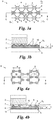
Fig. 2a und 2b einen Ausschnitt einer ersten Variante der Leckschutzfolie vonFig. 1 in der Draufsicht (Fig. 2a ) bzw. als Detail A vonFig. 1 im Schnitt (Fig. 2b ) entlang der Schnittlinie B-B vonFig. 2a ; - die
Fig. 3a und 3b einen Ausschnitt einer zweiten Variante der Leckschutzfolie vonFig. 1 in der Draufsicht (Fig. 3a ) bzw. als Detail A vonFig. 1 im Schnitt (Fig. 3b ) entlang der Schnittlinie C-C vonFig. 3a ; und - die
Fig. 4a und 4b einen Ausschnitt einer dritten Variante der Leckschutzfolie vonFig. 1 in der Draufsicht (Fig. 4a ) bzw. als Detail A vonFig. 1 im Schnitt (Fig. 4b ) entlang der Schnittlinie D-D vonFig. 4a . - In
Fig. 1 ist ein Fluidtank 1 gezeigt, wie er beispielsweise als unterirdischer Kraftstofflagerbehälter in Tankstellen verwendet wird. Der Tank 1 hat eine Tankwandung 2 mit z.B. der Form eines Quaders, einer Kugel oder (hier:) eines liegenden Zylinders mit bombierten Enden 3, 4 und einer Öffnung 5, über welche der Tank 1 gefüllt, entleert und/oder erforderlichenfalls sogar betreten werden kann. Übliche Einbauten wie Füllstandsgeber, Entlüftungsöffnungen, Verstärkungsstege usw. des Tanks 1 sind inFig. 1 zwecks Übersichtlichkeit nicht dargestellt. - Zur Aufnahme von flüssigen oder gasförmigen Kraftstoffen oder anderen vielfach aggressiven Fluiden ist der Tank 1 gemäß
Fig. 1 mit einer Leckschutzfolie 6 ausgekleidet. Die Folie 6 ist aus einem luftdichten Material gefertigt, welches resistent gegen die aufzunehmenden Fluide ist. Dabei ist die Folie 6 - mit Ausnahme der Öffnung 6 - lückenlos an die Innenform des Tanks 1 angepasst. - Zum Auskleiden eines Tanks, z.B. beim Sanieren oder Nachrüsten, wird die Folie 6 beispielsweise in einem kollabierten Zustand durch die Öffnung 5 in das Tankinnere eingeführt und darin expandiert. Zum Expandieren wird gemäß einem dem Fachmann bekannten Verfahren die Folie 6 im Tankinneren aufgeblasen und/oder der Raum zwischen Folie 6 und Tankwandung 2 evakuiert. Montagepersonal ist dazu im Tankinneren nicht erforderlich. Um das Einführen der Folie 6 durch die Öffnung 5 eines bestehenden Tanks zu ermöglichen, ist das Material der Folie 6 flexibel. Je flexibler die Folie 6 ist, desto einfacher lässt sie sich durch die Öffnung 5 einführen und im Tankinneren expandieren, desto geringer ist allerdings auch die mechanische Belastbarkeit der Folie 6.
- Der Fluidtank 1 hat gemäß
Fig. 1 zwischen Tankwandung 2 und Folie 6 einen durchgängigen Hohlraum 7. Der Tank 1 ist somit doppelwandig, sodass ein Doppelwand-Leckschutzüberwachungssystem aufgebaut werden kann, wenn gewünscht oder erforderlich. Dazu wird der Hohlraum 7 im Betrieb des Tanks 1 unter Unterdruck (evakuiert) oder Überdruck (druckbeaufschlagt) gesetzt und mittels einer Druckmesseinrichtung auf Druckkonstanz überwacht. Wird dabei ein Ansteigen des Unterdrucks oder ein Abfallen des Überdrucks registriert, wird daraus auf ein Leck in der Tankwandung 2 und/oder der Folie 6 geschlossen. - Die Folie 6 hat dazu gemäß einer ersten, nicht näher dargestellten Ausführungsform an ihrer der Tankwandung 2 zuzuwendenden Außenseite Sa Noppen 8, welche direkt aus dem Folienmaterial selbst ("in einem Guss") ausgeformt sind. Die Noppen 8 stützen die Folie 6 der Tankwandung 2 ab, wenn der Tank 1 fertig ausgekleidet ist. Auf diese Weise wird der genannte durchgängige Hohlraum 7 zwischen Tankwandung 2 und Folie 6 mithilfe der Noppen 8 ausgebildet.
- Anhand der
Fig. 2 bis 4 werden im Folgenden verschiedene weitere Ausführungsformen der Leckschutzfolie 6 näher erläutert. - In der Ausführungsform gemäß den
Fig. 2a und 2b hat die Folie 6 zur Verstärkung - insbesondere zur Erhöhung der Druckfestigkeit der Folie 6 - an ihrer der Tankwandung 2 zuzuwendenden Außenseite Sa optionale Rippen 9 ausgeformt. An den Rippen 9, d.h. sich von diesen weiter abhebend, sind die Noppen 8 ausgeformt, sodass die Folie 6 im Betrieb des Tanks 1 ausschließlich von den Noppen 8, nicht von den Rippen 9, an der Tankwandung 2 abgestützt ist. Zwischen benachbarten Rippen 9 liegen Mulden 10, in welchen die Folie 6 ihre geringste Wandstärke w aufweist. Diese geringste Wandstärke w an einer zwischen Rippen 9 liegenden Mulde 10 beträgt - im unbelasteten Zustand der Folie 6 - beispielsweise zwischen 50% und 70% der Gesamtdicke d der Folie 6; im Bereich einer der Rippen 9 kann dabei die Wandstärke w' der Folie 6 beispielsweise zwischen 70% und 90% der Gesamtdicke d der Folie 6 liegen. - Die Rippen 9 können z.B. alle zueinander parallel - auch wellen- oder zickzackförmig und somit stückweise zueinander parallel - angeordnet und/oder unterbrochen sein, wenn gewünscht, um beispielsweise an Faltungsstellen der kollabierten Folie 6 oder an Kanten in der Tankwandung 2 flexibler zu sein. Im Beispiel der
Fig. 2a sind die Rippen 9 in zwei Gruppen G1, G2 jeweils zueinander parallel angeordnet, wobei die Rippen 9 einer Gruppe G1 jene der anderen Gruppe G2 kreuzen. An jedem Kreuzungspunkt der Rippen 9 ist, sich von diesen weiter abhebend, eine Noppe 8 ausgeformt. So bilden die Rippen 9 Parallelogramme - im Beispiel derFig. 2a und 2b Rauten - in anderen Fällen Rechtecke oder Quadrate, mit zwischenliegenden Mulden 10 und an den Eckpunkten ausgeformten Noppen 8. - Das Beispiel der
Fig. 3a und 3b ist jenem derFig. 2a und 2b ähnlich, jedoch sind die zueinander jeweils parallelen Rippen 9 in drei einander kreuzenden Gruppen G1, G2, G3 angeordnet, sodass die Rippen 9 Dreiecke - hier beinahe gleichseitige Dreiecke - mit zwischenliegenden Mulden 10 bilden. Die Noppen 8 sind wieder an den Eckpunkten ausgeformt. - Es versteht sich, dass die Rippen 9 mehr als drei Gruppen G1, G2, ..., allgemein Gi, bilden können und/oder einander in anderer Weise kreuzen können, sodass sie beispielsweise - anders als in den dargestellten Beispielen - keine kongruenten Mulden 10 bilden. Auch könnten einzelne Rippen 9 oder ein Gruppe Gi paralleler Rippen 9 weniger stark ausgeformt, d.h. weniger erhaben, oder die Rippen 9 überhaupt unregelmäßig angeordnet sein.
- Die Rippen 9 des Beispiels der
Fig. 4a und 4b sind in Wabenstruktur angeordnet. Dabei sind im Schnitt derFig. 4b die unterschiedlichen Wandstärken w bzw. w' der Folie 6 im Bereich einer Mulde 10 bzw. der Rippen 9 ersichtlich. Auch andere wabenähnliche Strukturen, z.B. eine Abfolge von Vier- und Achtecken od. dgl., sind alternativ möglich. - Die Folie 6 ist beispielsweise aus einem Polyurethan oder einem anderen flexiblen, luftdichten, fluid-resistenten Material gefertigt. Sie kann ein Gesamtdicke d - einschließlich der Noppen 8 - von einigen Zehntel Millimetern bis einigen Millimetern, bevorzugt zwischen einem und drei Millimetern, haben. Auch die Noppen 8 haben einen gegenseitigen Abstand a von einigen Zehntel Millimetern bis einigen Millimetern, bevorzugt zwischen einem halben und etwa zwei Millimetern, wobei die Abstände a zwischen in verschiedenen Richtungen benachbarten Noppen 8 ein und derselben Folie 6 aufgrund ihrer Strukturierung im Allgemeinen unterschiedlich groß sind. Ferner kann der Querschnitt der Noppen 8 rund oder - wie in den dargestellten Beispielen - oval sein, aber auch eine andere Form haben.
- Die Folie 6 kann an ihrer den Noppen 8 abgewandten Innenseite Si glatt oder rau sein und hat im letzteren Fall beispielsweise eine Rautiefe, d.h. eine Differenz aus maximaler und minimaler Oberflächenhöhe, zwischen 20 µm und 200 µm, bevorzugt etwa 100 µm. Optional ist die Folie 6 ferner an ihrer Innenseite Si mit einer elektrisch leitfähigen Deckschicht 11 (
Fig. 4b ), z.B. einer Metallfolie, einer elektrischen Leitpaste od.dgl., beschichtet. - Die Erfindung ist nicht auf die dargestellten Ausführungsformen beschränkt, sondern umfasst alle Varianten, Modifikationen und Kombinationen, die in den Rahmen der angeschlossenen Ansprüche fallen.
Claims (9)
- Leckschutzfolie zum Auskleiden eines Fluidtanks (1), welche Folie (6) aus einem flexiblen, luftdichten, fluid-resistenten Material zur Anpassung an eine Innenform des Tanks (1) gefertigt ist, wobei die Folie (6) an einer Außenseite (Sa) zur Zuwendung zur Tankwandung (2) direkt aus Folienmaterial ausgeformte Noppen (8) zur Abstützung der Folie (6) an der Tankwandung (2) im ausgekleideten Tank (1) und zur Ausbildung eines durchgängigen Hohlraums (7) zwischen Tankwandung (2) und Folie (6) hat, dadurch gekennzeichnet, dass die Folie (6) ferner an ihrer Außenseite (Sa) direkt aus dem Folienmaterial ausgeformte Rippen (9) hat, sodass das Folienmaterial in zwischen den Rippen (9) sich ausbildenden Mulden (10) dünner ausgeführt ist, an welchen Rippen (9) sich von diesen weiter abhebend die Noppen (8) ausgeformt sind, wobei entweder die Rippen (9) in zumindest zwei einander kreuzenden Gruppen (Gi) jeweils zueinander parallel angeordnet sind und an jedem Kreuzungspunkt eine Noppe (8) ausgeformt ist, oder die Rippen (9) in Wabenstruktur angeordnet sind und an jedem Wabeneckpunkt eine Noppe (8) ausgeformt ist.
- Leckschutzfolie nach Anspruch 1, dadurch gekennzeichnet, dass die Folie (6) an einer Rippe (9) zwischen 70% und 90% ihrer Gesamtdicke (d) und in einer zwischen Rippen (9) liegenden Mulde (10) zwischen 50% bis 70 % ihrer Gesamtdicke (d) hat.
- Leckschutzfolie nach Anspruch 1 oder 2, dadurch gekennzeichnet, dass die Folie (6) einschließlich der Noppen (8) eine Gesamtdicke (d) von einigen Zehntel Millimetern bis einigen Millimetern, bevorzugt zwischen einem und drei Millimetern, hat.
- Leckschutzfolie nach einem der Ansprüche 1 bis 3, dadurch gekennzeichnet, dass die Noppen (8) einen gegenseitigen Abstand (a) von einigen Zehntel Millimetern bis einigen Millimetern, bevorzugt zwischen einem halben und etwa zwei Millimetern, haben.
- Leckschutzfolie nach Anspruch 4, dadurch gekennzeichnet, dass die Abstände (a) zwischen in verschiedenen Richtungen benachbarten Noppen (8) der Folie (6) unterschiedlich groß sind.
- Leckschutzfolie nach einem der Ansprüche 1 bis 5, dadurch gekennzeichnet, dass die Folie (6) an ihrer den Noppen (8) abgewandten Innenseite (Si) rau ist mit einer Rautiefe zwischen 20 µm und 200 µm, bevorzugt etwa 100 µm.
- Leckschutzfolie nach Anspruch 6, dadurch gekennzeichnet, dass die Folie (6) an ihrer Innenseite (Si) mit einer elektrisch leitfähigen Deckschicht (11) beschichtet ist.
- Leckschutzfolie nach einem der Ansprüche 1 bis 7, dadurch gekennzeichnet, dass das Folienmaterial ein Polyurethan ist.
- Leckschutzfolie nach einem der Ansprüche 1 bis 8, dadurch gekennzeichnet, dass die Folie (6) zum Einführen in einen Fluidtank (1) kollabierbar und zum Auskleiden des Tanks (1) darin expandierbar ist.
Applications Claiming Priority (2)
| Application Number | Priority Date | Filing Date | Title |
|---|---|---|---|
| ATA50534/2016A AT518760B1 (de) | 2016-06-13 | 2016-06-13 | Leckschutzfolie für einen Fluidtank |
| PCT/AT2017/060105 WO2017214646A1 (de) | 2016-06-13 | 2017-04-24 | Leckschutzfolie für einen fluidtank |
Publications (2)
| Publication Number | Publication Date |
|---|---|
| EP3468897A1 EP3468897A1 (de) | 2019-04-17 |
| EP3468897B1 true EP3468897B1 (de) | 2020-04-01 |
Family
ID=58640649
Family Applications (1)
| Application Number | Title | Priority Date | Filing Date |
|---|---|---|---|
| EP17719990.8A Active EP3468897B1 (de) | 2016-06-13 | 2017-04-24 | Leckschutzfolie für einen fluidtank |
Country Status (4)
| Country | Link |
|---|---|
| EP (1) | EP3468897B1 (de) |
| AT (1) | AT518760B1 (de) |
| RU (1) | RU2734886C2 (de) |
| WO (1) | WO2017214646A1 (de) |
Family Cites Families (17)
| Publication number | Priority date | Publication date | Assignee | Title |
|---|---|---|---|---|
| DE1147089B (de) * | 1960-05-19 | 1963-04-11 | Hovalwerk Ag Ospelt | Lagerbehaelter mit Innenblase fuer Fluessigkeiten, insbesondere fuer Heizoel |
| DE1812891A1 (de) * | 1968-12-05 | 1970-06-18 | Gerhard Weiske | Zwischenlage fuer eine Leckschutzauskleidung bei Lagerbehaeltern |
| CA943884A (en) * | 1971-02-25 | 1974-03-19 | Arthur P. Martin | Collapsible suction-wall liner |
| CH603443A5 (en) * | 1976-09-14 | 1978-08-15 | Schaerer Max Alexander | Leak-proof double walled liquid storage container |
| US4613922A (en) * | 1984-01-11 | 1986-09-23 | Neo Vac Aktiengesellschaft | Double-grounded wall tank, and method of its manufacture |
| CH672110A5 (de) * | 1986-04-07 | 1989-10-31 | Adisa Entwicklungs Ag | |
| EP0754635A1 (de) * | 1995-07-17 | 1997-01-22 | Adisa Service und Entwicklungs AG | Doppelwandiger Tank und Verfahren zu dessen Herstellung |
| US5802631A (en) * | 1996-07-01 | 1998-09-08 | Friedman; Jerome | Pool liner installation method and apparatus |
| PL1602597T3 (pl) * | 2004-04-30 | 2007-05-31 | Wolftank Systems S P A | Powłoka wewnętrzna zbiornika z wypukłościami dystansowymi |
| CH705340B1 (de) * | 2007-02-02 | 2013-02-15 | Ono Waterprot Gmbh | Doppelwandiger Tank. |
| PL2055404T3 (pl) * | 2007-10-29 | 2010-10-29 | Ono Waterprotection Gmbh | Wytłaczana folia i sposób jej wytwarzania |
| EP2067719B1 (de) * | 2007-12-05 | 2012-02-01 | OnO Waterprotection GmbH | Distanzgebilde für die Leckschutzauskleidung eines Tanks, Leckschutzauskleidung und Tank mit einem solchen Distanzgebilde |
| RU108028U1 (ru) * | 2010-09-17 | 2011-09-10 | Открытое акционерное общество "Первая грузовая компания" | Мягкий вкладыш в вагон |
| ITVR20120180A1 (it) * | 2012-09-07 | 2014-03-08 | Ag | Metodo per realizzare una parete interna di metallo in un serbatoio e serbatoio avente una doppia parete. |
| WO2014117772A1 (de) * | 2013-02-04 | 2014-08-07 | Fenotec Gmbh Leckschutzsysteme | Innenauskleidung für einen tank oder einen behälter und anordnung |
| CN205087390U (zh) * | 2015-11-06 | 2016-03-16 | 洛阳展腾焊材有限公司 | 一种立式玻璃钢储罐 |
| CN207712732U (zh) * | 2017-12-28 | 2018-08-10 | 大连百利天华制药有限公司 | 冻干粉生产线上注射用水储罐 |
-
2016
- 2016-06-13 AT ATA50534/2016A patent/AT518760B1/de active
-
2017
- 2017-04-24 WO PCT/AT2017/060105 patent/WO2017214646A1/de not_active Ceased
- 2017-04-24 RU RU2018141214A patent/RU2734886C2/ru active
- 2017-04-24 EP EP17719990.8A patent/EP3468897B1/de active Active
Non-Patent Citations (1)
| Title |
|---|
| None * |
Also Published As
| Publication number | Publication date |
|---|---|
| AT518760B1 (de) | 2018-04-15 |
| WO2017214646A1 (de) | 2017-12-21 |
| RU2018141214A3 (de) | 2020-09-04 |
| RU2018141214A (ru) | 2020-05-25 |
| RU2734886C2 (ru) | 2020-10-23 |
| EP3468897A1 (de) | 2019-04-17 |
| AT518760A1 (de) | 2017-12-15 |
Similar Documents
| Publication | Publication Date | Title |
|---|---|---|
| EP2054561B1 (de) | Vakuumisolationspaneel mit durchführung | |
| EP2326865B1 (de) | Hochdruckbehälter | |
| DE2329321C3 (de) | Teleskopartiger Mast | |
| EP2514976A2 (de) | Druckgefäß mit definiertem Leckageweg | |
| DE1300064B (de) | Fluessigkeitsspeicheranlage | |
| EP2284428A1 (de) | Leitungsrohr und Verfahren zu seiner Herstellung | |
| DE202013101162U1 (de) | Tank für kryogene Fluide | |
| DE2633325C2 (de) | Isolierverkleidung zur Befestigung auf Anlagenteilen | |
| AT518760B1 (de) | Leckschutzfolie für einen Fluidtank | |
| DE102009014985B4 (de) | Flugzeugkabinen-Drainageleitung | |
| EP1953094B1 (de) | Doppelwandiger Tank | |
| DE102009024795A1 (de) | Wasserstofftank in einem Kraftfahrzeug | |
| DE102016110803B4 (de) | Druckbehälter | |
| EP2757302A1 (de) | Druckbehälter sowie Verfahren zum Herstellen eines Druckbehälters | |
| DE4134049A1 (de) | Dichtelement fuer muffenrohre | |
| DE202015005010U1 (de) | Wand,- Tür-oder Deckelelement für einen isolierenden Behälter | |
| DE3222064A1 (de) | Behaelter zur einlagerung von tiefgekuehlten fluessigkeiten | |
| DE10308576B4 (de) | Ringraumabdichtung | |
| EP3760415B1 (de) | Rohr | |
| EP0182242A2 (de) | Einrichtung zum Schutz wasserführender Kanäle gegen Druckwellen | |
| EP3483255B1 (de) | Verfahren zum schützen eines gärbehälters einer biogasanlage sowie gärbehälter einer biogasanlage | |
| DE2637011A1 (de) | Doppelwaendiger tank | |
| DE10113421A1 (de) | Stehender Flachbodentank, doppelwandig, in querovaler Form | |
| AT405891B (de) | Mikrowellengerät | |
| EP2441567B1 (de) | Verfahren zum Sanieren eines Tanks |
Legal Events
| Date | Code | Title | Description |
|---|---|---|---|
| STAA | Information on the status of an ep patent application or granted ep patent |
Free format text: STATUS: UNKNOWN |
|
| STAA | Information on the status of an ep patent application or granted ep patent |
Free format text: STATUS: THE INTERNATIONAL PUBLICATION HAS BEEN MADE |
|
| PUAI | Public reference made under article 153(3) epc to a published international application that has entered the european phase |
Free format text: ORIGINAL CODE: 0009012 |
|
| STAA | Information on the status of an ep patent application or granted ep patent |
Free format text: STATUS: REQUEST FOR EXAMINATION WAS MADE |
|
| 17P | Request for examination filed |
Effective date: 20181207 |
|
| AK | Designated contracting states |
Kind code of ref document: A1 Designated state(s): AL AT BE BG CH CY CZ DE DK EE ES FI FR GB GR HR HU IE IS IT LI LT LU LV MC MK MT NL NO PL PT RO RS SE SI SK SM TR |
|
| AX | Request for extension of the european patent |
Extension state: BA ME |
|
| DAV | Request for validation of the european patent (deleted) | ||
| DAX | Request for extension of the european patent (deleted) | ||
| GRAP | Despatch of communication of intention to grant a patent |
Free format text: ORIGINAL CODE: EPIDOSNIGR1 |
|
| STAA | Information on the status of an ep patent application or granted ep patent |
Free format text: STATUS: GRANT OF PATENT IS INTENDED |
|
| INTG | Intention to grant announced |
Effective date: 20191105 |
|
| GRAS | Grant fee paid |
Free format text: ORIGINAL CODE: EPIDOSNIGR3 |
|
| GRAA | (expected) grant |
Free format text: ORIGINAL CODE: 0009210 |
|
| STAA | Information on the status of an ep patent application or granted ep patent |
Free format text: STATUS: THE PATENT HAS BEEN GRANTED |
|
| AK | Designated contracting states |
Kind code of ref document: B1 Designated state(s): AL AT BE BG CH CY CZ DE DK EE ES FI FR GB GR HR HU IE IS IT LI LT LU LV MC MK MT NL NO PL PT RO RS SE SI SK SM TR |
|
| REG | Reference to a national code |
Ref country code: GB Ref legal event code: FG4D Free format text: NOT ENGLISH |
|
| REG | Reference to a national code |
Ref country code: CH Ref legal event code: EP Ref country code: AT Ref legal event code: REF Ref document number: 1251089 Country of ref document: AT Kind code of ref document: T Effective date: 20200415 |
|
| REG | Reference to a national code |
Ref country code: DE Ref legal event code: R096 Ref document number: 502017004518 Country of ref document: DE |
|
| REG | Reference to a national code |
Ref country code: IE Ref legal event code: FG4D Free format text: LANGUAGE OF EP DOCUMENT: GERMAN |
|
| REG | Reference to a national code |
Ref country code: CH Ref legal event code: NV Representative=s name: HEPP WENGER RYFFEL AG, CH |
|
| PG25 | Lapsed in a contracting state [announced via postgrant information from national office to epo] |
Ref country code: BG Free format text: LAPSE BECAUSE OF FAILURE TO SUBMIT A TRANSLATION OF THE DESCRIPTION OR TO PAY THE FEE WITHIN THE PRESCRIBED TIME-LIMIT Effective date: 20200701 |
|
| REG | Reference to a national code |
Ref country code: NL Ref legal event code: MP Effective date: 20200401 |
|
| REG | Reference to a national code |
Ref country code: LT Ref legal event code: MG4D |
|
| PG25 | Lapsed in a contracting state [announced via postgrant information from national office to epo] |
Ref country code: SE Free format text: LAPSE BECAUSE OF FAILURE TO SUBMIT A TRANSLATION OF THE DESCRIPTION OR TO PAY THE FEE WITHIN THE PRESCRIBED TIME-LIMIT Effective date: 20200401 Ref country code: NL Free format text: LAPSE BECAUSE OF FAILURE TO SUBMIT A TRANSLATION OF THE DESCRIPTION OR TO PAY THE FEE WITHIN THE PRESCRIBED TIME-LIMIT Effective date: 20200401 Ref country code: LT Free format text: LAPSE BECAUSE OF FAILURE TO SUBMIT A TRANSLATION OF THE DESCRIPTION OR TO PAY THE FEE WITHIN THE PRESCRIBED TIME-LIMIT Effective date: 20200401 Ref country code: GR Free format text: LAPSE BECAUSE OF FAILURE TO SUBMIT A TRANSLATION OF THE DESCRIPTION OR TO PAY THE FEE WITHIN THE PRESCRIBED TIME-LIMIT Effective date: 20200702 Ref country code: NO Free format text: LAPSE BECAUSE OF FAILURE TO SUBMIT A TRANSLATION OF THE DESCRIPTION OR TO PAY THE FEE WITHIN THE PRESCRIBED TIME-LIMIT Effective date: 20200701 Ref country code: IS Free format text: LAPSE BECAUSE OF FAILURE TO SUBMIT A TRANSLATION OF THE DESCRIPTION OR TO PAY THE FEE WITHIN THE PRESCRIBED TIME-LIMIT Effective date: 20200801 Ref country code: CZ Free format text: LAPSE BECAUSE OF FAILURE TO SUBMIT A TRANSLATION OF THE DESCRIPTION OR TO PAY THE FEE WITHIN THE PRESCRIBED TIME-LIMIT Effective date: 20200401 Ref country code: FI Free format text: LAPSE BECAUSE OF FAILURE TO SUBMIT A TRANSLATION OF THE DESCRIPTION OR TO PAY THE FEE WITHIN THE PRESCRIBED TIME-LIMIT Effective date: 20200401 Ref country code: PT Free format text: LAPSE BECAUSE OF FAILURE TO SUBMIT A TRANSLATION OF THE DESCRIPTION OR TO PAY THE FEE WITHIN THE PRESCRIBED TIME-LIMIT Effective date: 20200817 |
|
| PG25 | Lapsed in a contracting state [announced via postgrant information from national office to epo] |
Ref country code: RS Free format text: LAPSE BECAUSE OF FAILURE TO SUBMIT A TRANSLATION OF THE DESCRIPTION OR TO PAY THE FEE WITHIN THE PRESCRIBED TIME-LIMIT Effective date: 20200401 Ref country code: HR Free format text: LAPSE BECAUSE OF FAILURE TO SUBMIT A TRANSLATION OF THE DESCRIPTION OR TO PAY THE FEE WITHIN THE PRESCRIBED TIME-LIMIT Effective date: 20200401 Ref country code: LV Free format text: LAPSE BECAUSE OF FAILURE TO SUBMIT A TRANSLATION OF THE DESCRIPTION OR TO PAY THE FEE WITHIN THE PRESCRIBED TIME-LIMIT Effective date: 20200401 |
|
| PG25 | Lapsed in a contracting state [announced via postgrant information from national office to epo] |
Ref country code: AL Free format text: LAPSE BECAUSE OF FAILURE TO SUBMIT A TRANSLATION OF THE DESCRIPTION OR TO PAY THE FEE WITHIN THE PRESCRIBED TIME-LIMIT Effective date: 20200401 |
|
| REG | Reference to a national code |
Ref country code: DE Ref legal event code: R097 Ref document number: 502017004518 Country of ref document: DE |
|
| PG25 | Lapsed in a contracting state [announced via postgrant information from national office to epo] |
Ref country code: IT Free format text: LAPSE BECAUSE OF FAILURE TO SUBMIT A TRANSLATION OF THE DESCRIPTION OR TO PAY THE FEE WITHIN THE PRESCRIBED TIME-LIMIT Effective date: 20200401 Ref country code: MC Free format text: LAPSE BECAUSE OF FAILURE TO SUBMIT A TRANSLATION OF THE DESCRIPTION OR TO PAY THE FEE WITHIN THE PRESCRIBED TIME-LIMIT Effective date: 20200401 Ref country code: DK Free format text: LAPSE BECAUSE OF FAILURE TO SUBMIT A TRANSLATION OF THE DESCRIPTION OR TO PAY THE FEE WITHIN THE PRESCRIBED TIME-LIMIT Effective date: 20200401 Ref country code: LU Free format text: LAPSE BECAUSE OF NON-PAYMENT OF DUE FEES Effective date: 20200424 Ref country code: EE Free format text: LAPSE BECAUSE OF FAILURE TO SUBMIT A TRANSLATION OF THE DESCRIPTION OR TO PAY THE FEE WITHIN THE PRESCRIBED TIME-LIMIT Effective date: 20200401 Ref country code: SM Free format text: LAPSE BECAUSE OF FAILURE TO SUBMIT A TRANSLATION OF THE DESCRIPTION OR TO PAY THE FEE WITHIN THE PRESCRIBED TIME-LIMIT Effective date: 20200401 Ref country code: ES Free format text: LAPSE BECAUSE OF FAILURE TO SUBMIT A TRANSLATION OF THE DESCRIPTION OR TO PAY THE FEE WITHIN THE PRESCRIBED TIME-LIMIT Effective date: 20200401 Ref country code: RO Free format text: LAPSE BECAUSE OF FAILURE TO SUBMIT A TRANSLATION OF THE DESCRIPTION OR TO PAY THE FEE WITHIN THE PRESCRIBED TIME-LIMIT Effective date: 20200401 |
|
| REG | Reference to a national code |
Ref country code: BE Ref legal event code: MM Effective date: 20200430 |
|
| PLBE | No opposition filed within time limit |
Free format text: ORIGINAL CODE: 0009261 |
|
| STAA | Information on the status of an ep patent application or granted ep patent |
Free format text: STATUS: NO OPPOSITION FILED WITHIN TIME LIMIT |
|
| PG25 | Lapsed in a contracting state [announced via postgrant information from national office to epo] |
Ref country code: SK Free format text: LAPSE BECAUSE OF FAILURE TO SUBMIT A TRANSLATION OF THE DESCRIPTION OR TO PAY THE FEE WITHIN THE PRESCRIBED TIME-LIMIT Effective date: 20200401 Ref country code: PL Free format text: LAPSE BECAUSE OF FAILURE TO SUBMIT A TRANSLATION OF THE DESCRIPTION OR TO PAY THE FEE WITHIN THE PRESCRIBED TIME-LIMIT Effective date: 20200401 Ref country code: BE Free format text: LAPSE BECAUSE OF NON-PAYMENT OF DUE FEES Effective date: 20200430 |
|
| 26N | No opposition filed |
Effective date: 20210112 |
|
| PG25 | Lapsed in a contracting state [announced via postgrant information from national office to epo] |
Ref country code: IE Free format text: LAPSE BECAUSE OF NON-PAYMENT OF DUE FEES Effective date: 20200424 |
|
| PG25 | Lapsed in a contracting state [announced via postgrant information from national office to epo] |
Ref country code: SI Free format text: LAPSE BECAUSE OF FAILURE TO SUBMIT A TRANSLATION OF THE DESCRIPTION OR TO PAY THE FEE WITHIN THE PRESCRIBED TIME-LIMIT Effective date: 20200401 |
|
| PG25 | Lapsed in a contracting state [announced via postgrant information from national office to epo] |
Ref country code: TR Free format text: LAPSE BECAUSE OF FAILURE TO SUBMIT A TRANSLATION OF THE DESCRIPTION OR TO PAY THE FEE WITHIN THE PRESCRIBED TIME-LIMIT Effective date: 20200401 Ref country code: MT Free format text: LAPSE BECAUSE OF FAILURE TO SUBMIT A TRANSLATION OF THE DESCRIPTION OR TO PAY THE FEE WITHIN THE PRESCRIBED TIME-LIMIT Effective date: 20200401 Ref country code: CY Free format text: LAPSE BECAUSE OF FAILURE TO SUBMIT A TRANSLATION OF THE DESCRIPTION OR TO PAY THE FEE WITHIN THE PRESCRIBED TIME-LIMIT Effective date: 20200401 |
|
| PG25 | Lapsed in a contracting state [announced via postgrant information from national office to epo] |
Ref country code: MK Free format text: LAPSE BECAUSE OF FAILURE TO SUBMIT A TRANSLATION OF THE DESCRIPTION OR TO PAY THE FEE WITHIN THE PRESCRIBED TIME-LIMIT Effective date: 20200401 |
|
| P01 | Opt-out of the competence of the unified patent court (upc) registered |
Effective date: 20230427 |
|
| PGFP | Annual fee paid to national office [announced via postgrant information from national office to epo] |
Ref country code: DE Payment date: 20250417 Year of fee payment: 9 |
|
| PGFP | Annual fee paid to national office [announced via postgrant information from national office to epo] |
Ref country code: FR Payment date: 20250422 Year of fee payment: 9 |
|
| PGFP | Annual fee paid to national office [announced via postgrant information from national office to epo] |
Ref country code: CH Payment date: 20250501 Year of fee payment: 9 |
|
| PGFP | Annual fee paid to national office [announced via postgrant information from national office to epo] |
Ref country code: AT Payment date: 20250327 Year of fee payment: 9 |
|
| PGFP | Annual fee paid to national office [announced via postgrant information from national office to epo] |
Ref country code: GB Payment date: 20260331 Year of fee payment: 10 |
|
| REG | Reference to a national code |
Ref country code: CH Ref legal event code: U11 Free format text: ST27 STATUS EVENT CODE: U-0-0-U10-U11 (AS PROVIDED BY THE NATIONAL OFFICE) Effective date: 20260501 |