EP3468738B1 - Elektrodenhalter für funkenerosionsbearbeitung - Google Patents
Elektrodenhalter für funkenerosionsbearbeitung Download PDFInfo
- Publication number
- EP3468738B1 EP3468738B1 EP17813720.4A EP17813720A EP3468738B1 EP 3468738 B1 EP3468738 B1 EP 3468738B1 EP 17813720 A EP17813720 A EP 17813720A EP 3468738 B1 EP3468738 B1 EP 3468738B1
- Authority
- EP
- European Patent Office
- Prior art keywords
- electrode
- spindle
- contact element
- sleeve
- groove
- Prior art date
- Legal status (The legal status is an assumption and is not a legal conclusion. Google has not performed a legal analysis and makes no representation as to the accuracy of the status listed.)
- Active
Links
- 238000009760 electrical discharge machining Methods 0.000 title claims description 21
- 238000011010 flushing procedure Methods 0.000 claims description 7
- 239000012530 fluid Substances 0.000 claims description 3
- 238000000034 method Methods 0.000 description 5
- 230000008901 benefit Effects 0.000 description 4
- 238000003754 machining Methods 0.000 description 4
- 125000006850 spacer group Chemical group 0.000 description 4
- 230000003247 decreasing effect Effects 0.000 description 2
- 238000003780 insertion Methods 0.000 description 2
- 230000037431 insertion Effects 0.000 description 2
- 230000000670 limiting effect Effects 0.000 description 2
- 239000000463 material Substances 0.000 description 2
- 230000002829 reductive effect Effects 0.000 description 2
- 230000000284 resting effect Effects 0.000 description 2
- 230000007723 transport mechanism Effects 0.000 description 2
- 230000004075 alteration Effects 0.000 description 1
- 238000010276 construction Methods 0.000 description 1
- 230000001419 dependent effect Effects 0.000 description 1
- 238000011161 development Methods 0.000 description 1
- 230000018109 developmental process Effects 0.000 description 1
- 238000005553 drilling Methods 0.000 description 1
- 230000003628 erosive effect Effects 0.000 description 1
- 230000036541 health Effects 0.000 description 1
- 238000004519 manufacturing process Methods 0.000 description 1
- 238000003825 pressing Methods 0.000 description 1
- 230000008569 process Effects 0.000 description 1
- 238000007789 sealing Methods 0.000 description 1
Images


Classifications
-
- B—PERFORMING OPERATIONS; TRANSPORTING
- B23—MACHINE TOOLS; METAL-WORKING NOT OTHERWISE PROVIDED FOR
- B23H—WORKING OF METAL BY THE ACTION OF A HIGH CONCENTRATION OF ELECTRIC CURRENT ON A WORKPIECE USING AN ELECTRODE WHICH TAKES THE PLACE OF A TOOL; SUCH WORKING COMBINED WITH OTHER FORMS OF WORKING OF METAL
- B23H7/00—Processes or apparatus applicable to both electrical discharge machining and electrochemical machining
- B23H7/26—Apparatus for moving or positioning electrode relatively to workpiece; Mounting of electrode
- B23H7/265—Mounting of one or more thin electrodes
-
- B—PERFORMING OPERATIONS; TRANSPORTING
- B23—MACHINE TOOLS; METAL-WORKING NOT OTHERWISE PROVIDED FOR
- B23H—WORKING OF METAL BY THE ACTION OF A HIGH CONCENTRATION OF ELECTRIC CURRENT ON A WORKPIECE USING AN ELECTRODE WHICH TAKES THE PLACE OF A TOOL; SUCH WORKING COMBINED WITH OTHER FORMS OF WORKING OF METAL
- B23H7/00—Processes or apparatus applicable to both electrical discharge machining and electrochemical machining
- B23H7/26—Apparatus for moving or positioning electrode relatively to workpiece; Mounting of electrode
-
- B—PERFORMING OPERATIONS; TRANSPORTING
- B23—MACHINE TOOLS; METAL-WORKING NOT OTHERWISE PROVIDED FOR
- B23B—TURNING; BORING
- B23B31/00—Chucks; Expansion mandrels; Adaptations thereof for remote control
- B23B31/02—Chucks
- B23B31/10—Chucks characterised by the retaining or gripping devices or their immediate operating means
- B23B31/101—Chucks with separately-acting jaws movable radially
-
- B—PERFORMING OPERATIONS; TRANSPORTING
- B23—MACHINE TOOLS; METAL-WORKING NOT OTHERWISE PROVIDED FOR
- B23B—TURNING; BORING
- B23B2260/00—Details of constructional elements
- B23B2260/022—Balls
-
- B—PERFORMING OPERATIONS; TRANSPORTING
- B23—MACHINE TOOLS; METAL-WORKING NOT OTHERWISE PROVIDED FOR
- B23H—WORKING OF METAL BY THE ACTION OF A HIGH CONCENTRATION OF ELECTRIC CURRENT ON A WORKPIECE USING AN ELECTRODE WHICH TAKES THE PLACE OF A TOOL; SUCH WORKING COMBINED WITH OTHER FORMS OF WORKING OF METAL
- B23H2400/00—Moving mechanisms for tool electrodes
- B23H2400/10—Moving mechanisms for tool electrodes for rotating the electrode
-
- B—PERFORMING OPERATIONS; TRANSPORTING
- B23—MACHINE TOOLS; METAL-WORKING NOT OTHERWISE PROVIDED FOR
- B23H—WORKING OF METAL BY THE ACTION OF A HIGH CONCENTRATION OF ELECTRIC CURRENT ON A WORKPIECE USING AN ELECTRODE WHICH TAKES THE PLACE OF A TOOL; SUCH WORKING COMBINED WITH OTHER FORMS OF WORKING OF METAL
- B23H2500/00—Holding and positioning of tool electrodes
Definitions
- the embodiments of the present invention relate to electrical discharge machining (EDM) systems and methods, and more particularly to systems and methods for the handling of electrodes within such systems and methods.
- EDM electrical discharge machining
- EDM Electrical discharge machining
- spark machining also referred to as spark machining, spark eroding, burning, die sinking, wire burning, or wire erosion
- spark machining is a manufacturing process whereby a desired shape is obtained using electrical discharges.
- Material is removed from the workpiece by a series of rapidly recurring current discharges between two electrodes.
- One of the electrodes is the tool, or simply the electrode, and the other of the electrodes is the workpiece.
- the electrode is consumed during the EDM process. Consequently, spent electrodes must be replaced regularly with new electrodes. Because the EDM system is not operating while the electrodes are being replaced, replacing electrodes results in downtime and reduced machine utilization. The amount of downtime during the electrode replacement depends in part on how quickly the operator notices the need for a replacement and in part on the skill and the speed of the operator in making the replacement. When the EDM machining requires a relatively high rate of electrode consumption (e.g. speed drilling), machine utilization is particularly low.
- Typical electrode holders are in the form of manually operated chucks having radially symmetrical jaws that tighten or expand to hold or release the electrode.
- Chucks often require the use of a tool or manual grasping to tighten or loosen the chuck jaws in order to insert or release the electrode.
- the use of a tool or manually operating the chuck to tighten/loosen the chuck can be cumbersome and increase loading and unloading time. Chucks can be improperly tightened, which can increase the risk of damaging the electrodes.
- the chucks are removable from the machine for loading and unloading the electrodes, further increasing the loading and unloading time as well as increasing the risk of damaging the electrodes.
- Patent document EP 1721693 A1 relates to an electric discharge machining apparatus that makes a hole in a workpiece to be machined and, in particular, to an electric discharge machining apparatus that is suitable for use in making a fine hole in a workpiece to be machined by means of electric discharge machining using a small-diameter wire as an electrode.
- an EDM electrode holder reduces electrode replacement time and reduces the risk of damaging electrodes during loading, thus increasing machine utilization and decreasing costs.
- the embodiments of the invention can provide a number of advantages. Firstly, the system reduces machine downtime. Secondly, the system reduces the risk of damage to the electrodes that may occur during manual handling. Thirdly, the system reduces the time required to replace an electrode by removing the need to manually tighten and loosen manual chucks. Fourthly, the system reduces possible health risks to an operator in view of the reduced exposure to the EDM environment.
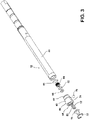
- the EDM machine 10 includes a spindle 12 and a spindle transport mechanism 14.
- the spindle 12 releasably holds an electrode 16 for use in removing material from a workpiece.
- the spindle transport mechanism 14 moves the spindle 12 in the X, Y, and Z directions and is also referred to as an XYZ tool jig base.
- the EDM machine 10 can include additional components, such as a support frame, a workpiece support, a control system operatively connected with one or more components of the EDM machine 10 to control their movement, and other elements known in the EDM art, the details of which are not necessary for a complete understanding of the embodiments of the invention.
- the EDM machine 10 includes a housing 20 for supporting the spindle 12 and additional components relative to the spindle 12.
- the housing 20 can support a drive system 22 that is operatively connected with the spindle 12 to selectively rotate the spindle 12.
- the housing 20 can also support pneumatic cylinder 24 having a piston rod 26 that is coupled with a frame 30.
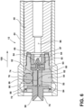
- the spindle 12 can include a spindle body 40 ( Fig. 3 ) having an elongated shape extending along a longitudinal axis 42 oriented along the length of the electrode 16.
- a sleeve 44 at least partially encompasses the spindle body 40 and extends along at least a portion of the length of the spindle body 40.
- the spindle 12 further includes a biasing element 46, such as a spring, which is received on the spindle body 40 for biasing the sleeve 44 relative to the spindle body 40.
- the sleeve 44 can include a rim 48 which is configured to engage an adjacent portion of the frame 30 for selectively moving the sleeve 44 relative to the spindle body 40.
- the spindle 12 further includes a pair of first and second contact elements 50, 52 which are configured to receive the electrode 16 therebetween to releasably hold the electrode 16 relative to the spindle body 40.
- the pair of contact elements 50, 52 can be received within a spindle collar 54 which is coupled with an open end of the spindle body 40.
- the spindle collar 54 includes a first open end 56, connected with a second open end 58 by a side wall 60.
- An electrode seal 62 is received within the second open end 58 of the spindle collar 54 for forming a seal around the electrode 16.
- Additional components, such as a seal spacer 63, a set screw 64, and an O-ring 66 can also be provided within the second open end 58 to seal the electrode 16 and to couple the spindle collar 54 with the spindle body 40.
- the spindle 12 includes an electrode guide 70 for guiding the electrode 16 to the pair of contact elements 50, 52.
- the electrode guide 70 is received within the first open end 56 of the spindle collar 54 adjacent the contact elements 50, 52 and a snap ring 72 can be provided for holding the electrode guide 70 in place within the spindle collar 54.
- the electrode guide 70 and snap ring 72 can function together to secure the contact elements 50, 52 within the spindle collar 54.
- alternative retainers such as a washer or spring retainer can be used to hold the contact elements 50, 52 within the spindle collar 54.
- the spindle collar 54 can also include at least one aperture 74 within the side wall 60 that is at least partially aligned with one of the contact elements 50, 52.
- the aperture 74 can be configured to receive a locking element 76 which selectively applies a clamping pressure to the adjacent contact element 50, 52 to press the adjacent contact element 50, 52 toward the other contact element 50, 52 to clamp the electrode 16 therein.
- Figs. 4 and 5 illustrate the pair of first and second contact elements 50 and 52, respectively.
- the first contact element 50 includes a first clamping surface 80 having a groove 82 formed therein that is configured to receive an electrode 82 therein.
- the first clamping surface 80 can also be provided with a first cavity 84 having angled walls that taper toward the groove 82 for guiding the electrode 16 into the groove 82.
- the second contact element 52 can include a second clamping surface 86 that is generally planar.
- the second clamping surface 86 can also include a second cavity 88 at one end having angled walls that taper toward a center of the second clamping surface 86.
- the second cavity 88 in the second clamping surface 86 can be configured to be generally aligned with the first cavity 84 when the first and second contact elements 50 and 52 are assembled within the spindle 12. In this manner, the first and second cavities 84 and 88 in the first and second clamping surfaces 80 and 86, respectively, can cooperate to guide the electrode 16 into the groove 82.
- first contact element 50 is illustrated as having a groove 82 therein, it will be understood that the second contact element 52 can have a similar groove formed therein in addition to the first contact element 50.
- first and/or second contact elements 50, 52 or neither can include the cavity 84, 88 for guiding the electrode 16 into the groove 82.
- the electrode guide 70 includes a passageway 90, which can optionally include an inwardly tapered entry for guiding the electrode 16 to the passageway 90, through which the electrode 16 can travel to the first and second contact elements 50, 52.
- the seal spacer 63 can include a passageway 92, which can optionally include an inwardly tapered entry, through which the electrode 16 can travel to the electrode seal 62.
- the electrode seal 62 can include a passageway 94, which can also optionally include an inwardly tapered entry, which is configured to allow the electrode 16 to pass through to a flushing chamber 96 provided within the spindle body 40.
- the electrode seal 62 can have a generally cone-shaped body 97 that receives the electrode 16 and extends into the flushing chamber 96. Fluid supplied to the flushing chamber 96 impacts the cone-shaped body 97 and applies pressure to the cone-shaped body 97 of the electrode seal 62 to facilitate forming a seal around the electrode 16 inserted therethrough.
- the sleeve 44 can include a recess 98 on an interior surface thereof that can be selectively aligned with the locking element 76 to allow the locking element 76 to move relative to the first and second contact elements 50, 52.
- the sleeve 44 can be moved along the spindle body 40 in the direction illustrated by arrow 100 to an open position in which the recess 98 is at least partially aligned with the locking element 76, as illustrated in Fig. 7 .
- the electrode 16 can be inserted through the passageway 90 in the electrode guide 70 which is aligned with the groove 82 in the first clamping surface 80.
- the cavities 84 and 88 in the first and second contacts 50, 52 can facilitate guiding the electrode 16 from the passageway 90 of the electrode guide 70 to the groove 82.
- the electrode 16 can travel through the first and second contacts 50, 52 to the electrode seal 62 through the seal spacer 63 until at least a portion of the electrode 16 extends into the flushing chamber 96.
- the electrode 16 can be removed by withdrawing the electrode 16 in the opposite direction as just described.
- the sleeve 44 can be moved into the open position pneumatically by the pneumatic cylinder 24.
- a source of gas such as compressed air (not shown) can be fluidly coupled with the pneumatic cylinder 24 for selectively supplying a gas to the pneumatic cylinder 24.
- the source of gas can include one or more valves that are operably coupled with a controller (not shown) that receive input from a suitable user interface, such as a manually operated switch or a computer-assisted interface, for controlling the flow of gas to the pneumatic cylinder 24.
- the controller When the controller receives an input indicating that the sleeve 44 is to be moved into the open position, the controller controls the source of gas to supply gas to the pneumatic cylinder 24 to cause the piston rod 26 to retract. As the piston rod 26 retracts, the frame 30 is drawn upward, which in turn draws the sleeve 44 upward into the open position against the bias of the biasing element 46 due to the engagement between the sleeve rim 48 and the frame 30.
- Electrodes 16 can be inserted into and/or removed from the spindle 12 manually by hand or automatically using an automated electrode changer, such as that disclosed in U.S. Pat. No. 9,314,860, entitled “Electrical Discharge Machining Automated Electrode Changer,” issued April 19, 2016 , the content of which is incorporated herein in its entirety.
- the sleeve 44 can be moved relative to the spindle body 40 in the direction indicated by arrow 110 to the clamping position illustrated in Fig. 6 .
- the controller controls the source of gas to supply gas to the pneumatic cylinder 24 to cause the piston rod 26 to extend and lower the frame 30 back into the resting position illustrated in Fig. 2 .
- the frame 30 In the resting position, the frame 30 is no longer pressing the sleeve 44 against the bias of the biasing element 46, which allows the biasing element 46 to press the sleeve 44 downward relative to the spindle body 40 into the clamping position illustrated in Fig. 6 .
- the sleeve 44 applies pressure to the locking element 76 which forces the locking element 76 to press against the second contact element 52.
- Pressure from the locking element 76 forces the second contact element 52 to shift toward the first contact element 50, thereby clamping the electrode 16 which had been previously inserted therein.
- the size of the electrode 16, the size of the groove 82, and the distance the second contact element 52 moves when the locking element 76 is pressed against the second contact element 52 can be configured to provide a desired amount of clamping pressure to the electrode 16 to hold the electrode 16 within the spindle 12.
- the second clamping surface 86 can apply pressure to the electrode 16 to clamp the electrode 16 within the groove 82 of the first clamping surface 80.
- the cone-shaped body 97 of the electrode seal 62 allows the passageway 94 of the electrode seal 62 to be sized so as to allow the electrode 16 to pass through with little to no resistance to facilitate loading and unloading the electrode 16.
- pressure from the flushing fluid supplied to the flushing chamber 96 impacts the cone-shaped body 97 of the electrode seal 62, sealing the electrode seal 62 against the electrode 16.
- the spindle 12 can be configured such that the first contact element 50 with the groove 82 is movable for clamping and releasing the electrode 16.
- the spindle collar 54 can include a second aperture 74 and a corresponding second locking element 76 adjacent the first contact element 50, such that a clamping force is selectively applied to and released from both the first and second contact elements 50, 52 when the sleeve 44 is moved between the clamping and open positions.
- the locking element 76 is in the form of a ball and thus the locking element 76, spindle collar 54 and sleeve 44 together can form a ball lock for selectively clamping the electrode 16 between the first and second contact elements 50, 52.
- the locking element 76 can be in the form of a resilient element having a projection that extends through the aperture 74, similar to a spring lock design.
- the sleeve 44 applies a force against the resilient element which presses the locking element projection against the second contact element 52.
- the force on the resilient element is decreased enough to allow the resilient element to expand, withdrawing the projection away from the second contact element 52, thereby releasing the clamping pressure on the second contact element 52.
- the embodiments described herein provide for a pneumatically actuated electrode holder that clamps and unclamps an electrode with spring force without the use of tools.
- the designs described herein allow for the use of a permanently mounted electrode holder that does not require separate tools to use.
- Providing a groove in at least one of the contact elements can facilitate centering the electrode within the spindle in addition to improving the clamping pressure applied to the electrode.
- the disclosed embodiment includes a plurality of features that are described in concert and that might cooperatively provide a collection of benefits.
- the present invention is not limited to only those embodiments that include all of these features or that provide all of the stated benefits.
Claims (7)
- Funkenerosionsspindel (12) zum lösbaren Halten einer Elektrode (16), die Spindel umfassend:einen länglichen Spindelkörper (40), der eine Längsachse aufweist;eine bewegliche Hülse (44), die den Spindelkörper (40) umgibt und sich entlang der Längsachse erstreckt;ein erstes Kontaktelement (50), das eine erste Elektrodenklemmfläche (80) aufweist, umfassend eine Nut (82), die sich entlang der Längsachse erstreckt, wobei die Nut (82) konfiguriert ist, um die Elektrode (16) darin aufzunehmen;ein zweites Kontaktelement (52), das eine zweite Elektrodenklemmfläche (86) aufweist, die an die erste Elektrodenklemmfläche (80) des ersten Kontaktelements (50) angrenzt;eine Elektrodenführung (70), die einen Durchgang (90) beinhaltet und konfiguriert ist, um die Elektrode (16) zu der ersten und der zweiten Elektrodenklemmfläche (80, 86) zu führen;ein Verriegelungselement (76), das durch die Hülse (44) betätigt wird, um selektiv Druck auf das zweite Kontaktelement (52) auszuüben;wobei die Hülse (44) entlang der Längsachse zwischen Folgendem beweglich ist:einer offenen Position, in der die Hülse (44) einen auf das Verriegelungselement (76) ausgeübten Druck freigibt, wodurch ein auf die erste und die zweite Elektrodenklemmfläche (80, 86) des ersten und des zweiten Kontaktelements (50, 52) ausgeübter Druck freigegeben wird; undeine Klemmposition, in der die Hülse (44) Druck auf das Verriegelungselement (76) ausübt, um das Verriegelungselement (76) gegen das zweite Kontaktelement (52) zu drücken, um die Elektrode (16) innerhalb der Nut (82) und zwischen der ersten und der zweiten Elektrodenklemmfläche (80, 86) zu klemmen; undein Vorspannelement (46), das die Hülse (44) in die Klemmposition vorspannt,dadurch gekennzeichnet, dass ein Druck des Verriegelungselements (76) das zweite Kontaktelement (52) zwingt, sich in Richtung des ersten Kontaktelements (50) zu verlagern; unddas erste Kontaktelement (50) mit der Nut (82) zum Festklemmen und Lösen der Elektrode (16) unbeweglich ist.
- Spindel (12) gemäß Anspruch 1, wobei das Verriegelungselement (76) eines von einer Kugel, einem Stift oder einer Feder umfasst.
- Spindel (12) gemäß Anspruch 1, wobei die zweite Elektrodenklemmfläche (86) eine ebene Oberfläche umfasst.
- Spindel (12) gemäß Anspruch 1, ferner umfassend einen Pneumatikzylinder (24), der konfiguriert ist, um die Hülse (44) gegen die Vorspannung des Vorspannelements (46) in die offene Position zu bewegen.
- Spindel (12) gemäß Anspruch 1, ferner umfassend eine Elektrodendichtung (62), die einen Durchgang (94) zum Aufnehmen der Elektrode (16) aufweist, wobei ein Druck aus einer Zufuhr von Spülflüssigkeit zu der Spindel die Elektrodendichtung (62) um die Elektrode (16) abdichtet.
- Spindel (12) gemäß Anspruch 1, wobei das erste Kontaktelement (50) einen ersten Hohlraum (84) definiert, der abgewinkelte Wände aufweist, die sich in Richtung der Nut (82) verjüngen, um die Elektrode (16) in die Nut (82) zu führen.
- Spindel (12) gemäß Anspruch 6, wobei das zweite Kontaktelement (52) einen zweiten Hohlraum (88) definiert, der abgewinkelte Wände aufweist, wobei der erste und der zweite Hohlraum (84, 88) konfiguriert sind, um zusammenzuwirken, um die Elektrode (16) in die Nut (82) zu führen.
Applications Claiming Priority (2)
| Application Number | Priority Date | Filing Date | Title |
|---|---|---|---|
| US15/181,855 US9776267B1 (en) | 2016-06-14 | 2016-06-14 | Electrical discharge machining electrode holder |
| PCT/US2017/022410 WO2017218059A1 (en) | 2016-06-14 | 2017-03-15 | Electrical discharge machining electrode holder |
Publications (3)
| Publication Number | Publication Date |
|---|---|
| EP3468738A1 EP3468738A1 (de) | 2019-04-17 |
| EP3468738A4 EP3468738A4 (de) | 2020-01-15 |
| EP3468738B1 true EP3468738B1 (de) | 2023-03-01 |
Family
ID=59929119
Family Applications (1)
| Application Number | Title | Priority Date | Filing Date |
|---|---|---|---|
| EP17813720.4A Active EP3468738B1 (de) | 2016-06-14 | 2017-03-15 | Elektrodenhalter für funkenerosionsbearbeitung |
Country Status (7)
| Country | Link |
|---|---|
| US (1) | US9776267B1 (de) |
| EP (1) | EP3468738B1 (de) |
| JP (1) | JP6847984B2 (de) |
| CN (1) | CN109311110B (de) |
| PL (1) | PL3468738T3 (de) |
| SG (2) | SG10202001548PA (de) |
| WO (1) | WO2017218059A1 (de) |
Families Citing this family (2)
| Publication number | Priority date | Publication date | Assignee | Title |
|---|---|---|---|---|
| CN108080759A (zh) * | 2017-12-18 | 2018-05-29 | 中国航发贵州黎阳航空动力有限公司 | 一种单极电脉冲小孔加工机用万能夹头 |
| CN110919113B (zh) * | 2019-12-11 | 2020-11-03 | 大连大学 | 一种横向馈电电极 |
Citations (1)
| Publication number | Priority date | Publication date | Assignee | Title |
|---|---|---|---|---|
| DE10103292B4 (de) * | 2001-01-25 | 2006-05-11 | Siemens Ag | Elektrodenführung für Erodiermaschinen sowie Verfahren zum Erodieren von Werkstücken |
Family Cites Families (25)
| Publication number | Priority date | Publication date | Assignee | Title |
|---|---|---|---|---|
| US4278245A (en) * | 1979-11-23 | 1981-07-14 | General Electric Company | Apparatus for clamping a plurality of elements |
| JPS6285329U (de) * | 1985-11-14 | 1987-05-30 | ||
| US5041709A (en) | 1988-05-03 | 1991-08-20 | Schneider James R | Attachment device for electrical discharge machine |
| JPH0441129A (ja) * | 1990-06-01 | 1992-02-12 | Mitsubishi Electric Corp | ワイヤ放電加工機 |
| CN2221464Y (zh) * | 1994-12-13 | 1996-03-06 | 山东工程学院 | 密封快换式电极夹头 |
| US5818006A (en) | 1995-12-07 | 1998-10-06 | Ford Global Technologies, Inc. | Surface preparation electrical discharge apparatus and method |
| DE69711557D1 (de) | 1996-12-06 | 2002-05-08 | System 3R Internat Ab Vaelling | Automatische luftdruckgesteuerte Werkzeugaufnahme |
| JPH10225823A (ja) * | 1997-02-10 | 1998-08-25 | Watanabe Tekko Kk | チャック装置 |
| JPH11320271A (ja) * | 1998-05-20 | 1999-11-24 | Toyota Motor Corp | 電極送給装置 |
| JP3708378B2 (ja) * | 1999-09-17 | 2005-10-19 | 株式会社ソディック | 細穴放電加工装置 |
| DE20120252U1 (de) * | 2001-01-25 | 2002-05-23 | Siemens Ag | Elektrodenführung für Erodiermaschinen |
| US7011661B2 (en) * | 2001-03-21 | 2006-03-14 | Medtronic, Inc. | Surgical instrument with rotary cutting member and quick release coupling arrangement |
| DE50210439D1 (de) * | 2001-04-27 | 2007-08-23 | Erowa Ag | Spannvorrichtung |
| GB0113879D0 (en) * | 2001-06-07 | 2001-08-01 | Amchem Ltd | Electrical discharge machining apparatus |
| CN2541110Y (zh) * | 2002-05-29 | 2003-03-26 | 苏州精机机械工业有限公司 | 飞碟式加工头 |
| JP4027770B2 (ja) * | 2002-10-18 | 2007-12-26 | 株式会社ソディック | 細穴放電加工装置 |
| CN100509234C (zh) * | 2004-01-23 | 2009-07-08 | 三菱电机株式会社 | 电火花加工设备 |
| CN100411795C (zh) | 2004-05-13 | 2008-08-20 | 嘉昇机电工业股份有限公司 | 细孔放电加工机自动更换电极装置 |
| IL172391A0 (en) * | 2005-12-06 | 2006-04-10 | Moshe Abraham | Attachment for spark erosion machines |
| JP2008200806A (ja) * | 2007-02-20 | 2008-09-04 | Denso Corp | 放電加工装置 |
| US8274008B2 (en) * | 2008-10-15 | 2012-09-25 | Lam Research Corporation | EDM spindle assembly with fluid seal |
| WO2011116826A1 (en) | 2010-03-25 | 2011-09-29 | Prometek Sa | A self-centering clamp for a cylindrical tool |
| US20120132623A1 (en) * | 2010-11-30 | 2012-05-31 | Justice Jr Jimmy Roger | Electrode holder |
| JP6077915B2 (ja) * | 2013-04-05 | 2017-02-08 | 株式会社エレニックス | 細穴放電加工装置および微細電極用電極ホルダ装置 |
| JP6289548B2 (ja) * | 2016-06-29 | 2018-03-07 | キヤノン株式会社 | デバイスおよびその制御方法、並びにプログラム |
-
2016
- 2016-06-14 US US15/181,855 patent/US9776267B1/en active Active
-
2017
- 2017-03-15 JP JP2018564873A patent/JP6847984B2/ja active Active
- 2017-03-15 EP EP17813720.4A patent/EP3468738B1/de active Active
- 2017-03-15 SG SG10202001548PA patent/SG10202001548PA/en unknown
- 2017-03-15 SG SG11201810499RA patent/SG11201810499RA/en unknown
- 2017-03-15 PL PL17813720.4T patent/PL3468738T3/pl unknown
- 2017-03-15 WO PCT/US2017/022410 patent/WO2017218059A1/en unknown
- 2017-03-15 CN CN201780034899.0A patent/CN109311110B/zh active Active
Patent Citations (1)
| Publication number | Priority date | Publication date | Assignee | Title |
|---|---|---|---|---|
| DE10103292B4 (de) * | 2001-01-25 | 2006-05-11 | Siemens Ag | Elektrodenführung für Erodiermaschinen sowie Verfahren zum Erodieren von Werkstücken |
Also Published As
| Publication number | Publication date |
|---|---|
| US9776267B1 (en) | 2017-10-03 |
| CN109311110A (zh) | 2019-02-05 |
| CN109311110B (zh) | 2021-04-30 |
| PL3468738T3 (pl) | 2023-07-10 |
| JP6847984B2 (ja) | 2021-03-24 |
| EP3468738A4 (de) | 2020-01-15 |
| SG11201810499RA (en) | 2018-12-28 |
| WO2017218059A1 (en) | 2017-12-21 |
| SG10202001548PA (en) | 2020-04-29 |
| EP3468738A1 (de) | 2019-04-17 |
| JP2019521866A (ja) | 2019-08-08 |
Similar Documents
| Publication | Publication Date | Title |
|---|---|---|
| US6095509A (en) | Clamping apparatus | |
| KR100528366B1 (ko) | 클램핑장치 | |
| KR101426825B1 (ko) | 클램프장치 | |
| KR100415483B1 (ko) | 클램프장치 | |
| JP5027133B2 (ja) | 工具用又はワーク用の位置決め・クランプ装置 | |
| KR101495888B1 (ko) | 에어 블로 중공형 핑거 척 | |
| EP3468738B1 (de) | Elektrodenhalter für funkenerosionsbearbeitung | |
| JP5892897B2 (ja) | クランプ装置 | |
| KR101275473B1 (ko) | 공작기계용 소재 그립장치 | |
| KR20220062615A (ko) | 워크 파지장치 | |
| WO2005070600A1 (ja) | 放電加工装置 | |
| JP2008006572A (ja) | 筒穴を有する鋳造物のクランプ治具 | |
| JP2008018499A (ja) | 型彫り・細穴複合放電加工方法および装置 | |
| EP1155757B1 (de) | Gesimsbiegemaschine mit pneumatischem Steuersystem zum Schnellspannen von Gesimsbiegewerkzeugen | |
| JP2017144546A (ja) | 仮ロック機能付きクランプ装置 | |
| JP2018069382A (ja) | リンク式クランプ装置 | |
| WO2019181430A1 (ja) | クランプシステム、クランプ方法およびクランプ装置 | |
| KR20150078483A (ko) | 스폿 용접용 용접팁 교환장치 | |
| JP2005212084A (ja) | チャック装置 | |
| CN106217079A (zh) | 一种用于螺杆加工定位的夹具 | |
| JP2009233760A (ja) | 治具パレットのワーククランプ装置 | |
| JP4461006B2 (ja) | 電極チップ交換装置 | |
| US20120126494A1 (en) | Pneumatic clamping cylinder | |
| CN210305821U (zh) | 一种数控车床多夹头液压软爪 | |
| CN212793377U (zh) | 一种铰孔自动定心工装 |
Legal Events
| Date | Code | Title | Description |
|---|---|---|---|
| STAA | Information on the status of an ep patent application or granted ep patent |
Free format text: STATUS: THE INTERNATIONAL PUBLICATION HAS BEEN MADE |
|
| PUAI | Public reference made under article 153(3) epc to a published international application that has entered the european phase |
Free format text: ORIGINAL CODE: 0009012 |
|
| STAA | Information on the status of an ep patent application or granted ep patent |
Free format text: STATUS: REQUEST FOR EXAMINATION WAS MADE |
|
| STAA | Information on the status of an ep patent application or granted ep patent |
Free format text: STATUS: REQUEST FOR EXAMINATION WAS MADE |
|
| 17P | Request for examination filed |
Effective date: 20181203 |
|
| AK | Designated contracting states |
Kind code of ref document: A1 Designated state(s): AL AT BE BG CH CY CZ DE DK EE ES FI FR GB GR HR HU IE IS IT LI LT LU LV MC MK MT NL NO PL PT RO RS SE SI SK SM TR |
|
| AX | Request for extension of the european patent |
Extension state: BA ME |
|
| RIN1 | Information on inventor provided before grant (corrected) |
Inventor name: IZWORSKI, MARK D. |
|
| DAV | Request for validation of the european patent (deleted) | ||
| DAX | Request for extension of the european patent (deleted) | ||
| REG | Reference to a national code |
Ref country code: DE Ref legal event code: R079 Ref document number: 602017066458 Country of ref document: DE Free format text: PREVIOUS MAIN CLASS: B23H0001040000 Ipc: B23H0007260000 |
|
| A4 | Supplementary search report drawn up and despatched |
Effective date: 20191216 |
|
| RIC1 | Information provided on ipc code assigned before grant |
Ipc: B23H 1/04 20060101ALI20191210BHEP Ipc: B23B 31/10 20060101ALI20191210BHEP Ipc: B23H 7/26 20060101AFI20191210BHEP Ipc: B23B 31/107 20060101ALI20191210BHEP |
|
| GRAP | Despatch of communication of intention to grant a patent |
Free format text: ORIGINAL CODE: EPIDOSNIGR1 |
|
| STAA | Information on the status of an ep patent application or granted ep patent |
Free format text: STATUS: GRANT OF PATENT IS INTENDED |
|
| INTG | Intention to grant announced |
Effective date: 20221025 |
|
| GRAS | Grant fee paid |
Free format text: ORIGINAL CODE: EPIDOSNIGR3 |
|
| GRAA | (expected) grant |
Free format text: ORIGINAL CODE: 0009210 |
|
| STAA | Information on the status of an ep patent application or granted ep patent |
Free format text: STATUS: THE PATENT HAS BEEN GRANTED |
|
| AK | Designated contracting states |
Kind code of ref document: B1 Designated state(s): AL AT BE BG CH CY CZ DE DK EE ES FI FR GB GR HR HU IE IS IT LI LT LU LV MC MK MT NL NO PL PT RO RS SE SI SK SM TR |
|
| REG | Reference to a national code |
Ref country code: GB Ref legal event code: FG4D |
|
| REG | Reference to a national code |
Ref country code: CH Ref legal event code: EP Ref country code: AT Ref legal event code: REF Ref document number: 1550638 Country of ref document: AT Kind code of ref document: T Effective date: 20230315 |
|
| REG | Reference to a national code |
Ref country code: DE Ref legal event code: R096 Ref document number: 602017066458 Country of ref document: DE |
|
| REG | Reference to a national code |
Ref country code: IE Ref legal event code: FG4D |
|
| PGFP | Annual fee paid to national office [announced via postgrant information from national office to epo] |
Ref country code: TR Payment date: 20230307 Year of fee payment: 7 |
|
| REG | Reference to a national code |
Ref country code: LT Ref legal event code: MG9D |
|
| P01 | Opt-out of the competence of the unified patent court (upc) registered |
Effective date: 20230522 |
|
| REG | Reference to a national code |
Ref country code: NL Ref legal event code: MP Effective date: 20230301 |
|
| PG25 | Lapsed in a contracting state [announced via postgrant information from national office to epo] |
Ref country code: RS Free format text: LAPSE BECAUSE OF FAILURE TO SUBMIT A TRANSLATION OF THE DESCRIPTION OR TO PAY THE FEE WITHIN THE PRESCRIBED TIME-LIMIT Effective date: 20230301 Ref country code: NO Free format text: LAPSE BECAUSE OF FAILURE TO SUBMIT A TRANSLATION OF THE DESCRIPTION OR TO PAY THE FEE WITHIN THE PRESCRIBED TIME-LIMIT Effective date: 20230601 Ref country code: LV Free format text: LAPSE BECAUSE OF FAILURE TO SUBMIT A TRANSLATION OF THE DESCRIPTION OR TO PAY THE FEE WITHIN THE PRESCRIBED TIME-LIMIT Effective date: 20230301 Ref country code: LT Free format text: LAPSE BECAUSE OF FAILURE TO SUBMIT A TRANSLATION OF THE DESCRIPTION OR TO PAY THE FEE WITHIN THE PRESCRIBED TIME-LIMIT Effective date: 20230301 Ref country code: HR Free format text: LAPSE BECAUSE OF FAILURE TO SUBMIT A TRANSLATION OF THE DESCRIPTION OR TO PAY THE FEE WITHIN THE PRESCRIBED TIME-LIMIT Effective date: 20230301 Ref country code: ES Free format text: LAPSE BECAUSE OF FAILURE TO SUBMIT A TRANSLATION OF THE DESCRIPTION OR TO PAY THE FEE WITHIN THE PRESCRIBED TIME-LIMIT Effective date: 20230301 |
|
| PGFP | Annual fee paid to national office [announced via postgrant information from national office to epo] |
Ref country code: IT Payment date: 20230310 Year of fee payment: 7 |
|
| REG | Reference to a national code |
Ref country code: AT Ref legal event code: MK05 Ref document number: 1550638 Country of ref document: AT Kind code of ref document: T Effective date: 20230301 |
|
| PG25 | Lapsed in a contracting state [announced via postgrant information from national office to epo] |
Ref country code: SE Free format text: LAPSE BECAUSE OF FAILURE TO SUBMIT A TRANSLATION OF THE DESCRIPTION OR TO PAY THE FEE WITHIN THE PRESCRIBED TIME-LIMIT Effective date: 20230301 Ref country code: NL Free format text: LAPSE BECAUSE OF FAILURE TO SUBMIT A TRANSLATION OF THE DESCRIPTION OR TO PAY THE FEE WITHIN THE PRESCRIBED TIME-LIMIT Effective date: 20230301 Ref country code: GR Free format text: LAPSE BECAUSE OF FAILURE TO SUBMIT A TRANSLATION OF THE DESCRIPTION OR TO PAY THE FEE WITHIN THE PRESCRIBED TIME-LIMIT Effective date: 20230602 Ref country code: FI Free format text: LAPSE BECAUSE OF FAILURE TO SUBMIT A TRANSLATION OF THE DESCRIPTION OR TO PAY THE FEE WITHIN THE PRESCRIBED TIME-LIMIT Effective date: 20230301 |
|
| PG25 | Lapsed in a contracting state [announced via postgrant information from national office to epo] |
Ref country code: SM Free format text: LAPSE BECAUSE OF FAILURE TO SUBMIT A TRANSLATION OF THE DESCRIPTION OR TO PAY THE FEE WITHIN THE PRESCRIBED TIME-LIMIT Effective date: 20230301 Ref country code: RO Free format text: LAPSE BECAUSE OF FAILURE TO SUBMIT A TRANSLATION OF THE DESCRIPTION OR TO PAY THE FEE WITHIN THE PRESCRIBED TIME-LIMIT Effective date: 20230301 Ref country code: PT Free format text: LAPSE BECAUSE OF FAILURE TO SUBMIT A TRANSLATION OF THE DESCRIPTION OR TO PAY THE FEE WITHIN THE PRESCRIBED TIME-LIMIT Effective date: 20230703 Ref country code: EE Free format text: LAPSE BECAUSE OF FAILURE TO SUBMIT A TRANSLATION OF THE DESCRIPTION OR TO PAY THE FEE WITHIN THE PRESCRIBED TIME-LIMIT Effective date: 20230301 Ref country code: CZ Free format text: LAPSE BECAUSE OF FAILURE TO SUBMIT A TRANSLATION OF THE DESCRIPTION OR TO PAY THE FEE WITHIN THE PRESCRIBED TIME-LIMIT Effective date: 20230301 Ref country code: AT Free format text: LAPSE BECAUSE OF FAILURE TO SUBMIT A TRANSLATION OF THE DESCRIPTION OR TO PAY THE FEE WITHIN THE PRESCRIBED TIME-LIMIT Effective date: 20230301 |
|
| REG | Reference to a national code |
Ref country code: CH Ref legal event code: PL |
|
| PG25 | Lapsed in a contracting state [announced via postgrant information from national office to epo] |
Ref country code: SK Free format text: LAPSE BECAUSE OF FAILURE TO SUBMIT A TRANSLATION OF THE DESCRIPTION OR TO PAY THE FEE WITHIN THE PRESCRIBED TIME-LIMIT Effective date: 20230301 Ref country code: IS Free format text: LAPSE BECAUSE OF FAILURE TO SUBMIT A TRANSLATION OF THE DESCRIPTION OR TO PAY THE FEE WITHIN THE PRESCRIBED TIME-LIMIT Effective date: 20230701 |
|
| PGFP | Annual fee paid to national office [announced via postgrant information from national office to epo] |
Ref country code: PL Payment date: 20230310 Year of fee payment: 7 |
|
| REG | Reference to a national code |
Ref country code: BE Ref legal event code: MM Effective date: 20230331 |
|
| REG | Reference to a national code |
Ref country code: DE Ref legal event code: R097 Ref document number: 602017066458 Country of ref document: DE |
|
| PG25 | Lapsed in a contracting state [announced via postgrant information from national office to epo] |
Ref country code: LU Free format text: LAPSE BECAUSE OF NON-PAYMENT OF DUE FEES Effective date: 20230315 |
|
| PLBE | No opposition filed within time limit |
Free format text: ORIGINAL CODE: 0009261 |
|
| STAA | Information on the status of an ep patent application or granted ep patent |
Free format text: STATUS: NO OPPOSITION FILED WITHIN TIME LIMIT |
|
| PG25 | Lapsed in a contracting state [announced via postgrant information from national office to epo] |
Ref country code: MC Free format text: LAPSE BECAUSE OF FAILURE TO SUBMIT A TRANSLATION OF THE DESCRIPTION OR TO PAY THE FEE WITHIN THE PRESCRIBED TIME-LIMIT Effective date: 20230301 |
|
| REG | Reference to a national code |
Ref country code: IE Ref legal event code: MM4A |
|
| PG25 | Lapsed in a contracting state [announced via postgrant information from national office to epo] |
Ref country code: SI Free format text: LAPSE BECAUSE OF FAILURE TO SUBMIT A TRANSLATION OF THE DESCRIPTION OR TO PAY THE FEE WITHIN THE PRESCRIBED TIME-LIMIT Effective date: 20230301 Ref country code: MC Free format text: LAPSE BECAUSE OF FAILURE TO SUBMIT A TRANSLATION OF THE DESCRIPTION OR TO PAY THE FEE WITHIN THE PRESCRIBED TIME-LIMIT Effective date: 20230301 Ref country code: LI Free format text: LAPSE BECAUSE OF NON-PAYMENT OF DUE FEES Effective date: 20230331 Ref country code: IE Free format text: LAPSE BECAUSE OF NON-PAYMENT OF DUE FEES Effective date: 20230315 Ref country code: FR Free format text: LAPSE BECAUSE OF NON-PAYMENT OF DUE FEES Effective date: 20230501 Ref country code: DK Free format text: LAPSE BECAUSE OF FAILURE TO SUBMIT A TRANSLATION OF THE DESCRIPTION OR TO PAY THE FEE WITHIN THE PRESCRIBED TIME-LIMIT Effective date: 20230301 Ref country code: CH Free format text: LAPSE BECAUSE OF NON-PAYMENT OF DUE FEES Effective date: 20230331 |
|
| 26N | No opposition filed |
Effective date: 20231204 |
|
| PG25 | Lapsed in a contracting state [announced via postgrant information from national office to epo] |
Ref country code: BE Free format text: LAPSE BECAUSE OF NON-PAYMENT OF DUE FEES Effective date: 20230331 |
|
| PGFP | Annual fee paid to national office [announced via postgrant information from national office to epo] |
Ref country code: DE Payment date: 20240220 Year of fee payment: 8 Ref country code: GB Payment date: 20240221 Year of fee payment: 8 |