EP3467300A1 - Nozzle - Google Patents
Nozzle Download PDFInfo
- Publication number
- EP3467300A1 EP3467300A1 EP18206998.9A EP18206998A EP3467300A1 EP 3467300 A1 EP3467300 A1 EP 3467300A1 EP 18206998 A EP18206998 A EP 18206998A EP 3467300 A1 EP3467300 A1 EP 3467300A1
- Authority
- EP
- European Patent Office
- Prior art keywords
- nozzle
- hole
- holes
- forming
- microstructured pattern
- Prior art date
- Legal status (The legal status is an assumption and is not a legal conclusion. Google has not performed a legal analysis and makes no representation as to the accuracy of the status listed.)
- Withdrawn
Links
Images


Classifications
-
- F—MECHANICAL ENGINEERING; LIGHTING; HEATING; WEAPONS; BLASTING
- F02—COMBUSTION ENGINES; HOT-GAS OR COMBUSTION-PRODUCT ENGINE PLANTS
- F02M—SUPPLYING COMBUSTION ENGINES IN GENERAL WITH COMBUSTIBLE MIXTURES OR CONSTITUENTS THEREOF
- F02M61/00—Fuel-injectors not provided for in groups F02M39/00 - F02M57/00 or F02M67/00
- F02M61/16—Details not provided for in, or of interest apart from, the apparatus of groups F02M61/02 - F02M61/14
-
- B—PERFORMING OPERATIONS; TRANSPORTING
- B29—WORKING OF PLASTICS; WORKING OF SUBSTANCES IN A PLASTIC STATE IN GENERAL
- B29C—SHAPING OR JOINING OF PLASTICS; SHAPING OF MATERIAL IN A PLASTIC STATE, NOT OTHERWISE PROVIDED FOR; AFTER-TREATMENT OF THE SHAPED PRODUCTS, e.g. REPAIRING
- B29C33/00—Moulds or cores; Details thereof or accessories therefor
- B29C33/42—Moulds or cores; Details thereof or accessories therefor characterised by the shape of the moulding surface, e.g. ribs or grooves
- B29C33/424—Moulding surfaces provided with means for marking or patterning
-
- C—CHEMISTRY; METALLURGY
- C25—ELECTROLYTIC OR ELECTROPHORETIC PROCESSES; APPARATUS THEREFOR
- C25D—PROCESSES FOR THE ELECTROLYTIC OR ELECTROPHORETIC PRODUCTION OF COATINGS; ELECTROFORMING; APPARATUS THEREFOR
- C25D1/00—Electroforming
- C25D1/08—Perforated or foraminous objects, e.g. sieves
-
- C—CHEMISTRY; METALLURGY
- C25—ELECTROLYTIC OR ELECTROPHORETIC PROCESSES; APPARATUS THEREFOR
- C25D—PROCESSES FOR THE ELECTROLYTIC OR ELECTROPHORETIC PRODUCTION OF COATINGS; ELECTROFORMING; APPARATUS THEREFOR
- C25D1/00—Electroforming
- C25D1/10—Moulds; Masks; Masterforms
-
- F—MECHANICAL ENGINEERING; LIGHTING; HEATING; WEAPONS; BLASTING
- F02—COMBUSTION ENGINES; HOT-GAS OR COMBUSTION-PRODUCT ENGINE PLANTS
- F02M—SUPPLYING COMBUSTION ENGINES IN GENERAL WITH COMBUSTIBLE MIXTURES OR CONSTITUENTS THEREOF
- F02M43/00—Fuel-injection apparatus operating simultaneously on two or more fuels, or on a liquid fuel and another liquid, e.g. the other liquid being an anti-knock additive
- F02M43/04—Injectors peculiar thereto
-
- F—MECHANICAL ENGINEERING; LIGHTING; HEATING; WEAPONS; BLASTING
- F02—COMBUSTION ENGINES; HOT-GAS OR COMBUSTION-PRODUCT ENGINE PLANTS
- F02M—SUPPLYING COMBUSTION ENGINES IN GENERAL WITH COMBUSTIBLE MIXTURES OR CONSTITUENTS THEREOF
- F02M61/00—Fuel-injectors not provided for in groups F02M39/00 - F02M57/00 or F02M67/00
- F02M61/16—Details not provided for in, or of interest apart from, the apparatus of groups F02M61/02 - F02M61/14
- F02M61/168—Assembling; Disassembling; Manufacturing; Adjusting
-
- F—MECHANICAL ENGINEERING; LIGHTING; HEATING; WEAPONS; BLASTING
- F02—COMBUSTION ENGINES; HOT-GAS OR COMBUSTION-PRODUCT ENGINE PLANTS
- F02M—SUPPLYING COMBUSTION ENGINES IN GENERAL WITH COMBUSTIBLE MIXTURES OR CONSTITUENTS THEREOF
- F02M61/00—Fuel-injectors not provided for in groups F02M39/00 - F02M57/00 or F02M67/00
- F02M61/16—Details not provided for in, or of interest apart from, the apparatus of groups F02M61/02 - F02M61/14
- F02M61/18—Injection nozzles, e.g. having valve seats; Details of valve member seated ends, not otherwise provided for
- F02M61/1806—Injection nozzles, e.g. having valve seats; Details of valve member seated ends, not otherwise provided for characterised by the arrangement of discharge orifices, e.g. orientation or size
- F02M61/1833—Discharge orifices having changing cross sections, e.g. being divergent
-
- F—MECHANICAL ENGINEERING; LIGHTING; HEATING; WEAPONS; BLASTING
- F02—COMBUSTION ENGINES; HOT-GAS OR COMBUSTION-PRODUCT ENGINE PLANTS
- F02M—SUPPLYING COMBUSTION ENGINES IN GENERAL WITH COMBUSTIBLE MIXTURES OR CONSTITUENTS THEREOF
- F02M61/00—Fuel-injectors not provided for in groups F02M39/00 - F02M57/00 or F02M67/00
- F02M61/16—Details not provided for in, or of interest apart from, the apparatus of groups F02M61/02 - F02M61/14
- F02M61/18—Injection nozzles, e.g. having valve seats; Details of valve member seated ends, not otherwise provided for
- F02M61/1806—Injection nozzles, e.g. having valve seats; Details of valve member seated ends, not otherwise provided for characterised by the arrangement of discharge orifices, e.g. orientation or size
- F02M61/184—Discharge orifices having non circular sections
-
- F—MECHANICAL ENGINEERING; LIGHTING; HEATING; WEAPONS; BLASTING
- F02—COMBUSTION ENGINES; HOT-GAS OR COMBUSTION-PRODUCT ENGINE PLANTS
- F02M—SUPPLYING COMBUSTION ENGINES IN GENERAL WITH COMBUSTIBLE MIXTURES OR CONSTITUENTS THEREOF
- F02M61/00—Fuel-injectors not provided for in groups F02M39/00 - F02M57/00 or F02M67/00
- F02M61/16—Details not provided for in, or of interest apart from, the apparatus of groups F02M61/02 - F02M61/14
- F02M61/18—Injection nozzles, e.g. having valve seats; Details of valve member seated ends, not otherwise provided for
- F02M61/1806—Injection nozzles, e.g. having valve seats; Details of valve member seated ends, not otherwise provided for characterised by the arrangement of discharge orifices, e.g. orientation or size
- F02M61/1846—Dimensional characteristics of discharge orifices
-
- F—MECHANICAL ENGINEERING; LIGHTING; HEATING; WEAPONS; BLASTING
- F02—COMBUSTION ENGINES; HOT-GAS OR COMBUSTION-PRODUCT ENGINE PLANTS
- F02M—SUPPLYING COMBUSTION ENGINES IN GENERAL WITH COMBUSTIBLE MIXTURES OR CONSTITUENTS THEREOF
- F02M61/00—Fuel-injectors not provided for in groups F02M39/00 - F02M57/00 or F02M67/00
- F02M61/16—Details not provided for in, or of interest apart from, the apparatus of groups F02M61/02 - F02M61/14
- F02M61/18—Injection nozzles, e.g. having valve seats; Details of valve member seated ends, not otherwise provided for
- F02M61/1853—Orifice plates
-
- F—MECHANICAL ENGINEERING; LIGHTING; HEATING; WEAPONS; BLASTING
- F02—COMBUSTION ENGINES; HOT-GAS OR COMBUSTION-PRODUCT ENGINE PLANTS
- F02M—SUPPLYING COMBUSTION ENGINES IN GENERAL WITH COMBUSTIBLE MIXTURES OR CONSTITUENTS THEREOF
- F02M2200/00—Details of fuel-injection apparatus, not otherwise provided for
- F02M2200/80—Fuel injection apparatus manufacture, repair or assembly
- F02M2200/8046—Fuel injection apparatus manufacture, repair or assembly the manufacture involving injection moulding, e.g. of plastic or metal
-
- F—MECHANICAL ENGINEERING; LIGHTING; HEATING; WEAPONS; BLASTING
- F02—COMBUSTION ENGINES; HOT-GAS OR COMBUSTION-PRODUCT ENGINE PLANTS
- F02M—SUPPLYING COMBUSTION ENGINES IN GENERAL WITH COMBUSTIBLE MIXTURES OR CONSTITUENTS THEREOF
- F02M2200/00—Details of fuel-injection apparatus, not otherwise provided for
- F02M2200/80—Fuel injection apparatus manufacture, repair or assembly
- F02M2200/8069—Fuel injection apparatus manufacture, repair or assembly involving removal of material from the fuel apparatus, e.g. by punching, hydro-erosion or mechanical operation
-
- F—MECHANICAL ENGINEERING; LIGHTING; HEATING; WEAPONS; BLASTING
- F02—COMBUSTION ENGINES; HOT-GAS OR COMBUSTION-PRODUCT ENGINE PLANTS
- F02M—SUPPLYING COMBUSTION ENGINES IN GENERAL WITH COMBUSTIBLE MIXTURES OR CONSTITUENTS THEREOF
- F02M2200/00—Details of fuel-injection apparatus, not otherwise provided for
- F02M2200/90—Selection of particular materials
- F02M2200/9092—Sintered materials
-
- Y—GENERAL TAGGING OF NEW TECHNOLOGICAL DEVELOPMENTS; GENERAL TAGGING OF CROSS-SECTIONAL TECHNOLOGIES SPANNING OVER SEVERAL SECTIONS OF THE IPC; TECHNICAL SUBJECTS COVERED BY FORMER USPC CROSS-REFERENCE ART COLLECTIONS [XRACs] AND DIGESTS
- Y10—TECHNICAL SUBJECTS COVERED BY FORMER USPC
- Y10T—TECHNICAL SUBJECTS COVERED BY FORMER US CLASSIFICATION
- Y10T29/00—Metal working
- Y10T29/49—Method of mechanical manufacture
- Y10T29/49405—Valve or choke making
-
- Y—GENERAL TAGGING OF NEW TECHNOLOGICAL DEVELOPMENTS; GENERAL TAGGING OF CROSS-SECTIONAL TECHNOLOGIES SPANNING OVER SEVERAL SECTIONS OF THE IPC; TECHNICAL SUBJECTS COVERED BY FORMER USPC CROSS-REFERENCE ART COLLECTIONS [XRACs] AND DIGESTS
- Y10—TECHNICAL SUBJECTS COVERED BY FORMER USPC
- Y10T—TECHNICAL SUBJECTS COVERED BY FORMER US CLASSIFICATION
- Y10T29/00—Metal working
- Y10T29/49—Method of mechanical manufacture
- Y10T29/4998—Combined manufacture including applying or shaping of fluent material
-
- Y—GENERAL TAGGING OF NEW TECHNOLOGICAL DEVELOPMENTS; GENERAL TAGGING OF CROSS-SECTIONAL TECHNOLOGIES SPANNING OVER SEVERAL SECTIONS OF THE IPC; TECHNICAL SUBJECTS COVERED BY FORMER USPC CROSS-REFERENCE ART COLLECTIONS [XRACs] AND DIGESTS
- Y10—TECHNICAL SUBJECTS COVERED BY FORMER USPC
- Y10T—TECHNICAL SUBJECTS COVERED BY FORMER US CLASSIFICATION
- Y10T428/00—Stock material or miscellaneous articles
- Y10T428/24—Structurally defined web or sheet [e.g., overall dimension, etc.]
- Y10T428/24273—Structurally defined web or sheet [e.g., overall dimension, etc.] including aperture
Definitions
- This invention generally relates to nozzles, including nozzles suitable for use in a fuel injector for an internal combustion engine.
- the invention is further applicable to fuel injectors incorporating such nozzles.
- This invention also relates to methods of making such nozzles.
- the invention is also applicable to methods of making fuel injectors incorporating such nozzles.
- Fuel injection is increasingly becoming the preferred method for mixing fuel and air in internal combustion engines. Fuel injection generally can be used to increase fuel efficiency of the engine and reduces hazardous emissions. Fuel injectors generally include a nozzle with a plurality of nozzle through-holes for atomizing the fuel under pressure for combustion. Increasing stringent environmental standards require more efficient fuel injectors.
- a method for making a nozzle.
- the method comprises: (a) providing a microstructured mold pattern defining at least a portion of a mold and comprising a plurality of replica nozzle holes and replica planar control cavities; (b) molding a first material into a nozzle forming microstructured pattern using the microstructured mold pattern, with the nozzle forming microstructured pattern comprising a plurality of nozzle hole forming features and planar control cavity forming features; (c) forming a second material into a nozzle pre-form using the nozzle forming microstructured pattern, with the nozzle pre-form comprising a plurality of nozzle pre-form holes and sacrificial planar control cavities; and (d) forming a nozzle from the nozzle pre-form, the forming the nozzle comprising removing enough of the second material to remove the sacrificial planar control cavities so as to form a top surface of the nozzle pre-form into a planar top surface of the nozzle,
- the microstructured mold pattern can be provided by (a) forming a third material into a mold forming microstructured pattern comprising a plurality of replica nozzle hole forming features and replica planar control cavity forming features; and (b) forming a fourth material into the microstructured mold pattern using the mold forming microstructured pattern, with the replica nozzle hole forming features being substantially negative replicas of the replica nozzle holes, and the replica planar control cavity forming features being substantially negative replicas of the replica planar control cavities.
- another method for making a nozzle.
- the method comprises: (a) providing a microstructured mold pattern defining at least a portion of a mold and comprising a plurality of replica nozzle holes; (b) molding a first material into a nozzle forming microstructured pattern using the microstructured mold pattern, with the nozzle forming microstructured pattern comprising a plurality of nozzle hole forming features; (c) forming a second material into a nozzle pre-form using the nozzle forming microstructured pattern, with the nozzle pre-form comprising a plurality of nozzle pre-form holes, the second material comprising a plurality of different second materials, and the nozzle pre-form is formed by sequentially depositing each of the second materials as a layer onto the nozzle forming microstructured pattern so that the resulting nozzle pre-form comprises a build-up of multiple layers, with each layer being a different second material; and (d) forming a nozzle from the nozzle pre-form, the
- the microstructured mold pattern can be provided by: (a) forming a third material into a mold forming microstructured pattern comprising a plurality of replica nozzle hole forming features; and (b) forming a fourth material into the microstructured mold pattern using the mold forming microstructured pattern, with the replica nozzle hole forming features being substantially negative replicas of the replica nozzle holes.
- a microstructured pattern for forming a nozzle pre-form comprising a plurality of nozzle pre-form holes, sacrificial planar control cavities and an outer planar periphery.
- the microstructured pattern comprises a plurality of nozzle hole forming features that are substantially negative replicas of the nozzle pre-form holes, and a plurality of planar control cavity forming features that are substantially negative replicas of the sacrificial planar control cavities.
- a nozzle pre-form for forming a nozzle comprising a plurality of nozzle through-holes, each nozzle through-hole comprising an inlet opening and at least one outlet opening connected to the inlet opening by a hollow cavity defined by an interior surface.
- the nozzle pre-form comprises a plurality of nozzle pre-form holes corresponding to the nozzle through-holes; and a plurality of sacrificial planar control cavities, wherein each of the nozzle pre-form holes is connected to at least one of the sacrificial planar control cavities.
- a nozzle in another aspect of the present invention, comprises a microstructured pattern comprising a plurality of nozzle through-holes, each nozzle through-hole comprising an inlet opening and at least one outlet opening connected to the inlet opening by a hollow cavity defined by an interior surface, wherein the microstructured pattern has an outer periphery, and the nozzle comprises a build-up of multiple layers, with each layer being a different material, and with either (a) none of the multiple layers being in the form of a thin electrically conductive seed layer, (b) the multiple layers being at least three layers, or (c) both (a) and (b).
- a nozzle in an additional aspect of the present invention, comprises a microstructured pattern comprising a plurality of nozzle through-holes, with each nozzle through-hole comprising an inlet opening and at least one outlet opening connected to the inlet opening by a hollow cavity defined by an interior surface, and the microstructured pattern having an outer periphery; and at least one fluid channel feature connecting at least one nozzle through-hole to (a) at least one other nozzle through-hole, (b) a portion of the outer periphery of the microstructured pattern, or (c) both (a) and (b).
- a nozzle in a further aspect of the present invention, comprises a microstructured pattern comprising a plurality of nozzle through-holes, with each nozzle through-hole comprising an inlet opening and at least one outlet opening connected to the inlet opening by a hollow cavity defined by an interior surface, and the microstructured pattern having an outer periphery; and at least one fluid plume shape-control feature for controlling the shape of a plume formed by a fluid flowing through and exiting the outlet openings of the nozzle through-holes.
- a nozzle in another aspect of the present invention, comprises a microstructured pattern comprising a plurality of nozzle through-holes, with each nozzle through-hole comprising an inlet opening and at least one outlet opening connected to the inlet opening by a hollow cavity defined by an interior surface, and the microstructured pattern having an outer periphery; and at least one nozzle through-hole having an interior surface that comprises at least one fluid flow affecting feature for causing cavitations, turbulence, or otherwise obstructing the flow of a fluid through the nozzle so as to positively affect a plume of droplets formed by the fluid passing through the nozzle through-hole and exiting the corresponding outlet opening of the nozzle through-hole.
- the disclosed nozzles include one or more through-holes designed to improve spray direction and fluid dynamics at the hole inlet, within the hole wall, and at the hole outlet.
- the disclosed nozzles can advantageously be incorporated into fuel injector systems to improve fuel efficiency.
- the disclosed nozzles can be fabricated using multiphoton, such as two photon, processes.
- multiphoton processes can be used to fabricate various microstructures.
- These microstructure can at least include one or more hole forming features, which can, in turn, be used as molds to fabricate holes for use in nozzles or other applications.
- nozzle may have a number of different meanings in the art.
- the term nozzle has a broad definition.
- U.S. Patent Publication No. 2009/0308953 A1 Patent et al.
- the nozzle of the current description would correspond generally to the orifice insert 24 of Palestrant et al.
- the nozzle of the current description can be understood as the final tapered portion of an atomizing spray system from which the spray is ultimately emitted, see e.g., Merriam Webster's dictionary definition of nozzle ("a short tube with a taper or constriction used (as on a hose) to speed up or direct a flow of fluid.” Further understanding may be gained by reference to U.S. Patent No. 5,716,009 (Ogihara et al. ) issued to Nippondenso Co., Ltd. (Kariya, Japan). In this reference, again, fluid injection "nozzle” is defined broadly as the multi-piece valve element 10 ("fuel injection valve 10 acting as fluid injection nozzle" - see col.
- nozzle as used herein would relate to first and second orifice plates 130 and 132 and potentially sleeve 138 (see Figs. 14 and 15 of Ogihara et al.), for example, which are located immediately proximate the fuel spray.
- a similar understanding of the term "nozzle” to that described herein is used in U.S. Patent No. 5,127,156 (Yokoyama et al. ) to Hitachi, Ltd. (Ibaraki, Japan).
- the nozzle 10 is defined separately from elements of the attached and integrated structure, such as "swirler” 12 (see Fig. 1(II) ).
- the above-defined understanding should be understood when the term "nozzle” is referred to throughout the remainder of the description and claims.
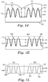
- a disclosed microstructure can be a three-dimensional rectilinear body such as a polyhedron, such as a tetrahedron or a hexahedron, a prism, or a pyramid, or a portion, or a combination, of such bodies, such as a frustum.
- Fig. 2 is a schematic three-dimensional view of a microstructure 220 that is disposed on a substrate 210 and includes a planar or flat base 230, a planar or flat top 240 and a side 250 that connects the top to the base.
- Side 250 includes a plurality of planar or flat facets, such as facets 260, 265 and 270.
- Microstructure 220 can be used as a mold to fabricate holes for use in, for example, a nozzle.
- a disclosed microstructure can be a three-dimensional curvilinear body or a portion of such body, such as a segment of a sphere, an asphere, an ellipsoid, a spheroid, a paraboloid, a cone or a truncated cone, or a cylinder.
- Fig. 3 is a schematic three-dimensional view of a microstructure 320 that is disposed on a substrate 310 and includes a planar or flat base 330, a planar or flat top 340 and a curvilinear side 350 that connects the top to the base.
- top 340 and base 330 have the same shape but different size.
- Microstructure 320 tapers narrower from base 330 to top 340. As a result, top 340 has a smaller area than base 330.
- Microstructure 320 can be used as a mold to fabricate holes for use in, for example, a nozzle.
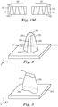
- a disclosed microstructure can be a tapered microstructure.
- Fig. 4 is a schematic three-dimensional view of a microstructure 420 that can be fabricated using a multiphoton process. Microstructure 420 can be used as a mold to fabricate holes for use in, for example, a nozzle. Microstructure 420 is disposed on a substrate 410 and includes a base 430, a top 440, and a side 450 connecting the top to the base. Microstructure 420 has a height or thickness h 1 which is the distance between base 430 and top 440 along the z-axis. Microstructure 420 is tapered.
- microstructure 420 includes a cross-section 460 at height h 2 in the xy-plane and a cross-section 470 at height h 3 > h 2 in the xy-plane.
- the area of cross-section 470 is less than the area of cross-section 460, and the area of cross-section 460 is less than the area of base 430.
- Base 430 has a first shape and top 440 has a second shape that is different than the first shape.
- the first shape is an elliptical shape and the second shape is a circular shape.
- Fig. 5 is a schematic three-dimensional view of a microstructure 520 that includes an elliptical base 530, a circular top 540, and a side 550 that connects the top to the base.
- Elliptical base 530 has a major axis 560 along the y-direction having a length "a" and a minor axis 570 along the x-direction having a length "b" different than "a”.
- Circular top 540 has a radius "r".
- Microstructure 520 is tapered. In particular, the area of circular top 540 is less than the area of elliptical base 530.
- the first shape can be a racetrack or oval and the second shape can, for example, be a circle.
- Fig. 6 is a schematic of a base 630 that can be the base of a disclosed microstructure.
- Base 630 includes two circles 642 and 644 and a middle portion 650.
- Base 630 has a perimeter 660 that includes curved portions or arcs 632 and 634 and linear portions 636 and 638.
- the circles 642 and 644 have a radius r a and r b , respectively, where r a and r b can be the same or different.
- Curved portions 632 and 634 are portions of respective circles 642 and 644.
- a disclosed microstructure has a cross-section along the thickness or height direction of the microstructure that rotates from the base of the microstructure to the top of the microstructure.
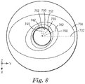
- Fig. 7 is a schematic three-dimensional view of a microstructure 720 that includes a base 730 disposed in the xy-plane, a top 740 disposed in the xy-plane, and a side 780 that connects the top to the base.
- Microstructure 720 has a height h 4 .
- Microstructure 720 has an xy cross-section that rotates clockwise from top 740 to base 730.
- top 740 has an axis of symmetry 742 along the x-direction
- an xy cross-section 750 of the microstructure at a height h 5 ⁇ h 4 has an axis of symmetry 752 that is rotated clockwise relative to axis of symmetry 742
- an xy cross-section 755 of the microstructure at a height h 6 ⁇ h 5 has an axis of symmetry 757 that is rotated clockwise relative to axis of symmetry 752
- an xy cross-section 760 of the microstructure at height a h 7 ⁇ h 6 has an axis of symmetry 762 that is rotated clockwise relative to axis of symmetry 757
- base 730 has an axis of symmetry 732 along the y-axis that is rotated clockwise relative to axis of symmetry 762.
- microstructure 720 has an xy cross-section that rotates counter clockwise from base 730 to top 740.
- Fig. 8 is a schematic top-view of microstructure 720 illustrating top 740 and its axis of symmetry 742, cross-section 750 and its axis of symmetry 752, cross-section 755 and its axis of symmetry 757, cross-section 760 and its axis of symmetry 762, and base 730 and its axis of symmetry 732. Viewed from the top, the axes of symmetry of the cross-sections rotate clockwise from the top to the base. Such a rotation results in a twist in the microstructure along its height or thickness.
- each cross-section can be an ellipse with a corresponding major axis acting as an axis of symmetry.
- the major axis rotates from the base to the top.
- the cross-sections rotate and become smaller from the base to the top.
- an elliptical base 730 has a major axis 732 along the y-direction having a length "a" and a minor axis 734 along the x-direction having a length "b" different than "a".
- a disclosed microstructure can include a taper and/or a twist or spiral along the thickness of the microstructure from the base to the top.
- Microstructure 720 can be used as a mold to fabricate one or more holes in a nozzle with the holes having substantially the same profile as microstructure 720.
- the fabrication results in a hole 720 having a hole entry 730, a hole exit 740 and a wall 752 extending from the hole entry to the hole exit.
- the hole tapers and spirals or twists from the hole entry to the hole exit.
- a disclosed spiraling or twisting nozzle hole can advantageously be used in a fuel injector to change the flow velocity of the fuel, reduce droplet size, and improve the mixing of fuel with air.
- the microstructure may be understood as having a "diameter" at different heights of the microstructure (e.g. h 6 , h 5 , etc.).
- the diameter may be understood as the maximum distance between the edges of the microstructure at a common height. In the situation, where there is an elliptical base, such as at hole entry 730, the diameter will be the distance between the edges of the microstructure along the major axis 732. At the opposite end of the structure, corresponding to hole exit 740, the diameter will similarly be the maximum distance between the edges of the microstructure at the common height (here, h 4 ). Thus, the distance between the edges of the microstructure along axis 742 will correspond to the diameter of the hole exit.
- the hole entry may have a diameter of less than 300 microns, or of less than 200 microns, or of less than or equal to 160 microns, or of less than 140 microns. In some embodiments the hole exit may have a diameter of less than 300 microns, or less than 200 microns, or less than 100 microns, or less than or equal to 40 microns, or less than 25 microns.
- the cross-section of nozzle hole 720 has an increasing rotation rate from the hole entry to the hole exit. In some cases, the cross-section of nozzle hole 720 has a decreasing rotation rate from the hole entry to the hole exit. In some cases, the cross-section has a constant rotation rate from the hole entry to the hole exit.
- a base or a lateral cross-section of a disclosed microstructure, or an entry hole or a lateral cross-section of a disclosed nozzle hole can have any cross-section that may be desirable in an application.
- the base or the entry hole can have a perimeter that includes the outer arcs of closely packed circles, where the outer arcs are connected by curve-like fillets.
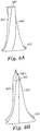
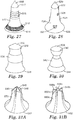
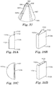
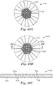
- Fig. 9A is a schematic three-dimensional view of a hole forming feature or microstructure 920 that includes a base 930 used to form the hole entry, a top 940 that can define the hole exit, and a side 950 that connects the base to the top and is used to define the walls of the hole.
- FIG. 9B is a schematic three-dimensional view of the hole forming feature or microstructure 920 with a replica planar control cavity forming feature 920a that is used to form a planar control cavity or planarization cone.
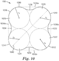
- Fig. 10 is a schematic of base 930 having a perimeter 1090 that includes the outer arcs of four closely packed circles, where the outer arcs are connected by curve-like fillets.
- perimeter 1090 includes an outer arc 1010 of a circle 1020, an outer arc 1012 of a circle 1022, an outer arc 1011 of a circle 1024, and an outer arc 1016 of a circle 1026, where outer arcs 1010 and 1012 are connected by curve-like fillet 1030 or straight line 1030a (shown in phantom), outer arcs 1012 and 1014 are connected by curve-like fillet 1032 or straight line 1032a (shown in phantom), outer arcs 1014 and 1016 are connected by curve-like fillet 1034 or straight line 1034a (shown in phantom), and outer arcs 1016 and 1010 are connected by curve-like fillet 1036 or straight line 1036a (shown in phantom).
- Circles 1010, 1012, 1014 and 1016 form a square array of equal and touching circles where each circle has a radius r 1 , r 2 , r 3 and r 4 that are all the same or
- Base 930 includes an axis of symmetry 1040.
- the lateral cross-sections of microstructure 920 rotate and the radius r 1 decreases from base 930 to top 940 resulting in a microstructure that spirals and tapers narrower from base 930 to top 940.
- a nozzle hole 920 includes a hole entry 930, a hole exit 940 and a wall 950 extending from the hole entry to the hole exit.
- Hole 920 has a lateral cross-section that rotates and becomes smaller from the hole entry to the hole exit.
- Fig. 11 is a schematic top-view of nozzle hole (or microstructure) 920 illustrating hole entry 930 having axis of symmetry 1040 and hole exit 940 having axis of symmetry 942. Viewed from the top, the axes of symmetry of the cross-sections of hole 920 rotate counter clockwise from the hole entry to the hole exit. Such a rotation results in a twist in the hole along its height or thickness.
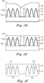
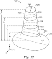
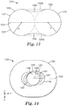
- Fig. 12 is a schematic three-dimensional view of a nozzle hole (or microstructure) 1220 that has a height k 1 and includes a hole entry 1230, a hole exit 1240, and a wall 1250 that extends from the hole entry to the hole exit.
- Fig. 13 is a schematic of hole entry 1230 having a perimeter 1235 that includes the outer arcs of two closely packed or touching circles, where the outer arcs are connected by curve-like fillets.
- perimeter 1090 includes an outer arc 1270 of a circle 1280 and an outer arc 1272 of a circle 1282, where each circle has a radius r 2 and outer arcs 1270 and 1272 are connected by curve-like fillets 1290 and 1292.
- Hole entry 1230 includes an axis of symmetry 1232.
- the lateral cross-sections of nozzle hole 1220 rotate and the radius r 2 decreases from hole entry 1230 to hole exit 1240 resulting in a microstructure that spirals and tapers narrower from hole entry 1230 to hole exit 1240.
- top 1240 has an axis of symmetry 1242 along the x-direction
- an xy cross-section 1264 of the hole at a height k 2 ⁇ k 1 has an axis of symmetry 1265 that is rotated clockwise relative to axis of symmetry 1242
- an xy cross-section 1262 of the hole at a height k 3 ⁇ k 2 has an axis of symmetry 1263 that is rotated clockwise relative to axis of symmetry 1265
- an xy cross-section 1260 of the hole at a height k 4 ⁇ k 3 has an axis of symmetry 1261 that is rotated clockwise relative to axis of symmetry 1263
- hole entry 1230 has an axis of symmetry 1232 along the y-axis that is rotated clockwise relative to axis of symmetry 1261.
- hole 1220 has an xy cross-section that rotates clockwise from hole exit 1240 to hole entry 1230. Equivalently, hole 1220 has an xy cross-section that rotates counter clockwise from the hole entry to the hole exit.
- Fig. 14 is a schematic top-view of nozzle hole 1220 illustrating hole exit 1242 and its axis of symmetry 1242 along the x-axis, cross-section 1264 and its axis of symmetry 1265, cross-section 1262 and its axis of symmetry 1263, cross-section 1260 and its axis of symmetry 1261, and hole entry 1230 and its axis of symmetry 1232 along the y-axis. Viewed from the top, the axes of symmetry of the lateral cross-sections of the hole rotate clockwise from the hole exit to the hole entry.
- a microstructure 1220 includes a base 1230, a top 1240 and a side 1250 that connects the base to the top.
- Microstructure 1220 has a cross-section that rotates and becomes smaller from the base to the top.
- the microstructures disclosed herein that serve as nozzles may be monolithic structures.
- the microstructures 220, 320, 420 etc. that forms the actual nozzles are created from, and ultimately form a common, single piece of material. This may be understood as different from nozzles that are formed through a combination of a number of different parts, where such parts are potentially made up of different materials.
- the nozzles disclosed herein may be monolithic structures.
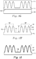
- a plurality of disclosed microstructures or holes can have any arrangement that may be desirable in an application.
- the disclosed holes can be arranged regularly or irregularly.
- Fig. 15A is a schematic top-view of a two-dimensional square array 1500 of holes or microstructures 1510
- Fig. 15B is a schematic top-view of a two-dimensional hexagonal array 1520 of holes or microstructures 1530, where holes or microstructures 1510 and 1530 can be any nozzle hole or microstructure disclosed herein.
- a plurality of disclosed microstructures or holes may be arranged on a non-planar surface.
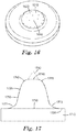
- Fig. 16 is a schematic three-dimensional view of a plurality of nozzle holes or microstructures 1610 disposed or arranged on a spherical surface 1620.
- a disclosed microstructure or hole may have one or more fillets for ease of manufacturing and/or to reduce local stress.
- Fig. 17 is a schematic side-view of a microstructure 1720 that is disposed on a substrate 1710 and includes a base 1730, a top 1740, and a side 1750 connecting the base to the top.
- Microstructure 1720 includes fillets 1760 and 1761 smoothly joining side 1750 and top 1740, and fillets 1770 and 1771 smoothly joining side 1750 and top surface 1705 of substrate 1710.
- nozzle through-holes or holes and the microstructured patterns or microstructures disclosed herein can be fabricated using the various methods disclosed herein, including the one outlined in reference to Figs. 1A-1M .
- the method provides flexibility and control in producing a variety of individual microstructures and holes in a single array, yet can be used to achieve desirably low levels of average surface roughness while maintaining industrially acceptable fabrication speeds or "throughput.”
- Fig. 1A is a schematic side-view of a layer 115 of a first material disposed on a substrate 110.
- the first material is capable of undergoing multiphoton reaction by simultaneously absorbing multiple photons.
- the first material is capable of undergoing a two photon reaction by simultaneously absorbing two photons.
- the first material can be any material or material system that is capable of undergoing multiphoton, such as two photon, reaction, such as those describe in pending U.S. Application Serial No. 11/313482 , "Process For Making Microlens Arrays And Masteroforms" (Attorney Docket No. 60893US002), filed December 21, 2005; U.S.
- Patent Application Publication US 2009/0175050 "Process For Making Light Guides With Extraction Structures And Light Guides Produced Thereby” (Attorney Docket No. 62162US007), filed May 17, 2007; and PCT Publication WO 2009/048705 , "Highly Functional Multiphoton Curable Reactive Species” (Attorney Docket No. 63221 WO003), filed September 9, 2008; all of which are incorporated herein by reference.
- the first material can be a photoreactive composition that includes at least one reactive species that is capable of undergoing an acid- or radical-initiated chemical reaction, and at least one multiphoton photoinitiator system.
- Reactive species suitable for use in the photoreactive compositions include both curable and non-curable species.
- Exemplary curable species include addition-polymerizable monomers and oligomers and addition-crosslinkable polymers (such as free-radically polymerizable or crosslinkable ethylenically-unsaturated species including, for example, acrylates, methacrylates, and certain vinyl compounds such as styrenes), as well as cationically-polymerizable monomers and oligomers and cationically-crosslinkable polymers (which species are most commonly acid-initiated and which include, for example, epoxies, vinyl ethers, cyanate esters, etc.), and the like, and mixtures thereof.
- Exemplary non-curable species include reactive polymers whose solubility can be increased upon acid- or radical-induced reaction.
- Such reactive polymers include, for example, aqueous insoluble polymers bearing ester groups that can be converted by photogenerated acid to aqueous soluble acid groups (for example, poly(4- tert -butoxycarbonyloxystyrene).
- Non-curable species also include the chemically-amplified photoresists.
- the multiphoton photoinitiator system enables polymerization to be confined or limited to the focal region of a focused beam of light used to expose the first material.
- a system preferably is a two- or three-component system that includes at least one multiphoton photosensitizer, at least one photoinitiator (or electron acceptor), and, optionally, at least one electron donor.
- Layer 115 of the first material can be coated on substrate 110 using any coating method that may be desirable in an application.
- the first material can be coated on substrate 110 by flood coating.
- Other exemplary coating methods include knife coating, notch coating, reverse roll coating, gravure coating, spray coating, bar coating, spin coating and dip coating.
- Substrate 110 can be chosen from a wide variety of films, sheets, and other surfaces (including silicon wafers and glass plates), depending upon the particular application and the method of exposure to be utilized. In some cases, substrate 110 is sufficiently flat so that layer 115 of the first material has a uniform thickness. In some cases, layer 115 can be exposed in bulk form. In such cases, substrate 110 may be excluded from the fabrication process. In some cases, such as when the process includes one or more electroplating steps, substrate 110 can be electrically conductive or semiconductive.
- the first material is selectively exposed to an incident light having sufficient intensity to cause simultaneous absorption of multiple photons by the first material in the exposed region.
- the exposure can be accomplished by any method that is capable of providing light with sufficient intensity. Exemplary exposure methods are described in U.S. Patent Application Publication US 2009/0099537 , "Process For Making Microneedles, Microneedle Arrays, Masters, And Replication Tools" (Attorney Docket No. 61795US005), filed March 23, 2007, which is incorporated herein by reference.
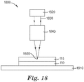
- Fig. 18 is a schematic side-view of an exemplary exposure system 1800 for exposing layer 115 of the first material.
- the exposure system includes a light source 1820 emitting light 1830 and a stage 1810 that is capable of moving in one, two, or three dimensions.
- Substrate 110 coated with layer of first material 115 is placed on the stage.
- Optical system 1840 focuses emitted light 1830 at a focal region 1850 within the first material.
- optical system 1840 is designed so that simultaneous absorption of multiple photons by the first material occurs only at or very near focal region 1850. Regions of layer 115 that undergo the multiphoton reaction become more, or less, soluble in at least one solvent compared to regions of layer 115 that do not undergo the multiphoton reaction.
- Focal region 1850 can scan a three-dimensional pattern within the first material by moving stage 1810 and/or light 1830 and/or one or more components, such as one or more mirrors, in optical system 1840.
- layer 115 is disposed on a planar substrate 110.
- substrate 110 can have any shape that may be desirable in an application.
- substrate 110 can have a spherical shape.
- Light source 1820 can be any light source that is capable of producing sufficient light intensity to effect multiphoton absorption.
- Exemplary light sources include lasers, such as femtosecond lasers, operating in a range from about 300 nm to about 1500 nm, or from about 400 nm to about 1100 nm, or from about 600 nm to about 900 nm, or from about 750 to about 850 nm.
- Optical system 1840 can include, for example, refractive optical elements (for example, lenses or microlens arrays), reflective optical elements (for example, retroreflectors or focusing mirrors), diffractive optical elements (for example, gratings, phase masks, and holograms), polarizing optical elements (for example, linear polarizers and waveplates), dispersive optical elements (for example, prisms and gratings), diffusers, Pockels cells, waveguides, and the like.
- refractive optical elements for example, lenses or microlens arrays
- reflective optical elements for example, retroreflectors or focusing mirrors
- diffractive optical elements for example, gratings, phase masks, and holograms
- polarizing optical elements for example, linear polarizers and waveplates
- dispersive optical elements for example, prisms and gratings
- diffusers for example, Pockels cells, waveguides, and the like.
- Such optical elements are useful for focusing
- solvents that can be used for developing the exposed first material include aqueous solvents such as, for example, water (for example, having a pH in a range of from 1 to 12) and miscible blends of water with organic solvents (for example, methanol, ethanol, propanol, acetone, acetonitrile, dimethylformamide, N-methylpyrrolidone, and the like, and mixtures thereof); and organic solvents.
- aqueous solvents such as, for example, water (for example, having a pH in a range of from 1 to 12) and miscible blends of water with organic solvents (for example, methanol, ethanol, propanol, acetone, acetonitrile, dimethylformamide, N-methylpyrrolidone, and the like, and mixtures thereof); and organic solvents.
- Exemplary useful organic solvents include alcohols (for example, methanol, ethanol, and propanol), ketones (for example, acetone, cyclopentanone, and methyl ethyl ketone), aromatics (for example, toluene), halocarbons (for example, methylene chloride and chloroform), nitriles (for example, acetonitrile), esters (for example, ethyl acetate and propylene glycol methyl ether acetate), ethers (for example, diethyl ether and tetrahydrofuran), amides (for example, N-methylpyrrolidone), and the like, and mixtures thereof.
- alcohols for example, methanol, ethanol, and propanol
- ketones for example, acetone, cyclopentanone, and methyl ethyl ketone
- aromatics for example, toluene
- halocarbons for example, methylene chloride and
- the first microstructured pattern includes a first cluster 122 of microstructures or features 120 and a second cluster 124 of microstructures or features 125, where microstructures 120 and 125 can be any microstructures including any microstructures disclosed herein. In some cases, microstructures 120 and 125 have different structures. In some cases, microstructures 120 and 125 have the same structure. In the exemplary first microstructured pattern 121, microstructures 120 and 125 have heights t 1 .
- Each microstructure 120 and 125 includes a replica nozzle hole forming feature 120b and 125b, and (differentiated by phantom lines) replica planar control cavity forming features 120a and 125a, which are used to form the planar control cavities or planarization cones.
- planarization cones it can be preferable for them to have a cone angle of about 45 degrees.
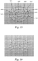
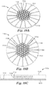
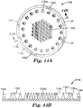
- Figs. 19 and 20 are scanning electron micrographs of a cluster or array of replica nozzle hole forming features or microstructures 120 fabricated according to the processes disclosed herein.
- the microstructures in Figs. 19 and 20 are similar to the nozzle hole forming features or microstructures 1220 shown in Fig. 12 .
- the microstructures are viewed along the minor axes of the bases of the microstructures and in Fig. 20 , the microstructures are viewed along the major axes of the bases of the microstructures.
- the plurality of microstructures or microstructured pattern in Fig. 19 are arranged in an array of concentric circles that includes an outermost circle 1910.
- the microstructures are arranged such that no diameter of the outermost circle includes at least one discrete microstructure from each circle in the array of concentric circles.
- a diameter 1920 of outermost circle 1910 includes microstructures 1901-1905 but not microstructures 1930 and 1931.
- Each circle in the array of concentric circles in Fig. 19 includes equally spaced discrete microstructures.
- a nozzle includes a plurality of holes that are arranged in an array of concentric circles that includes an outermost circle.
- Discrete nozzle holes or nozzle through-holes are arranged such that no diameter of the outermost circle includes at least one discrete nozzle hole from each circle in the array of concentric circles.
- each circle in the array of concentric circles comprises equally spaced discrete nozzle holes.
- the exposed or top surface 126 of first microstructured pattern 121 is metalized or made electrically conductive by coating the top surface with a thin electrically conductive seed layer 127.
- Conductive seed layer 127 can include any electrically conductive material that is desirable in an application. Exemplary conductive materials include silver, chromium, gold and titanium. In some cases, seed layer 127 has a thickness that is less than about 50 nm, or less than about 40 nm, or less than about 30 nm, or less than about 20 nm.
- seed layer 127 is used to electroplate first microstructured pattern 121 with a second material resulting in a layer 130 of the second material.
- the electroplating of first microstructured pattern 121 is continued until the minimum thickness t 2 of layer 130 is greater than t 1 .
- Suitable second materials for electroplating include silver, passivated silver, gold, rhodium, aluminum, enhanced reflectivity aluminum, copper, indium, nickel, chromium, tin, and alloys thereof.
- layer 130 of the second material has an uneven or rough top surface 132.
- layer 130 of the second material is polished or ground resulting in a layer 135 of the second material having a thickness t 3 >t 1 as illustrated schematically in Fig. 1E .
- the grinding or polishing can be accomplished using any grinding method that may be desirable in an application. Exemplary grinding methods include surface grinding and mechanical milling.
- layer of second material 130 can be directly deposited on first microstructured pattern 121 without first coating pattern 121 with seed layer 127.
- layer 130 can be coated on pattern 121 by any using suitable method including, for example, sputtering and chemical vapor deposition.
- substrate 110 and the first material are removed resulting in a first mold 140 of the second material shown schematically in Fig. 1F .
- seed layer 127 is not shown in Fig. 1F .
- substrate 110 and the patterned first material can be separated from layer 135 by hand. In some cases, the separation can be carried out prior to grinding layer 130.
- First mold 140 includes a second microstructured pattern 141 that is exactly, mostly or at least substantially the negative replica or image (e.g., reverse or mirror image) of first microstructured pattern 121.
- first mold 140 of the second material includes a first cluster 146 of microstructures 145 and a second cluster 147 of microstructures 148, where microstructures 145 are exactly, mostly or at least substantially negative replicas or images of microstructures 120 and microstructures 148 are exactly, mostly or at least substantially negative replicas or images of microstructures 125.
- the second microstructured pattern is replicated in a third material 150, which is the same or different than the first material and different than the second material, by disposing the third material in between first mold 140 of the second material and a substrate 155 having a smooth top surface 157 as schematically illustrated in Fig. 1G .
- the replication process can be accomplished using any suitable replication method.
- the replication can be accomplished by using an injection molding process.
- the first mold 140 and substrate 155 can form at least part of two halves of a molding die, and a molten third material 150 can be introduced between substrate 155 and first mold 140 and solidified after the molten third material fills the second microstructured pattern.
- the third material 150 can be any material that is capable of replicating a pattern.
- Exemplary third materials include polycarbonate and other thermoplastics such as polystyrene, acrylic, styrene acrylonitrile, poly-methyl methacrylate (PMMA), cyclo olefin polymer, polyethylene terephthalate, polyethylene 2,6-naphthalate, and fluoropolymers.
- thermoplastics such as polystyrene, acrylic, styrene acrylonitrile, poly-methyl methacrylate (PMMA), cyclo olefin polymer, polyethylene terephthalate, polyethylene 2,6-naphthalate, and fluoropolymers.
- first mold 140 of the second material and substrate 155 are removed resulting in a second mold 160 of the third material having a substrate portion 162 and a third microstructured pattern 161 that is exactly, mostly or at least substantially the negative replica or image (e.g., reverse or mirror image) of second microstructured pattern 141 and exactly, mostly or at least substantially a positive replica or image of first microstructured pattern 121.
- Third microstructured pattern 161 includes a first cluster 168 of microstructures 165 and a second cluster 169 of microstructures 159, where microstructures 165 are exactly, mostly or at least substantially negative replicas or images of microstructures 145 and microstructures 159 are exactly, mostly or at least substantially negative replicas or images of microstructures 148.
- microstructures 165 are exactly, mostly or at least substantially positive replicas or images of microstructures 120 and microstructures 159 are exactly, mostly or at least substantially positive replicas or images of microstructures 125.
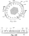
- Fig. 21 is a scanning electron micrograph of a cluster of polycarbonate microstructures 165 fabricated according to the processes disclosed herein.
- top surface 154 of third microstructured pattern 161 is metalized or made electrically conductive by coating the top surface with a thin electrically conductive seed layer 167 similar to seed layer 127.
- seed layer 167 is used to electroplate third microstructured pattern 161 with a fourth material different than the third material resulting in a nozzle pre-form or layer 170 of the fourth material having a top surface 172.
- the electroplating of second microstructured pattern 161 is continued until the minimum thickness t 5 of layer 130 is greater than t 4 , the height of the microstructures in second mold 160.
- height t 4 is substantially equal to height t 1 .
- Suitable fourth materials for electroplating include silver, passivated silver, gold, rhodium, aluminum, enhanced reflectivity aluminum, copper, indium, nickel, chromium, tin, and alloys thereof.
- the fourth material may be a ceramic that is deposited on third microstructured pattern 161.
- a ceramic material may be formed, e.g., by a sol-gel process as described in commonly owned and assigned U.S. Patent No. 5,453,104 , or by photocuring of a ceramic-filled or pre-ceramic polymeric composition as described in commonly owned and assigned U.S. Patents No. 6,572,693 , 6,387,981 , 6,899,948 , 7,393,882 , 7,297,374 , and 7,582,685 , each of which is herein incorporated by reference in its entirety.
- Such ceramic materials may comprise, e.g., silica, zirconia, alumina, titania, or oxides of yttrium, strontium, barium, hafnium, niobium, tantalum, tungsten, bismuth, molybdenum, tin, zinc, lanthanide elements (i.e. elements having atomic numbers ranging from 57 to 71, inclusive), cerium and combinations thereof.
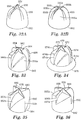
- the top surface 172 of the nozzle pre-form 170 is ground or otherwise removed until sacrificial planar control cavities 171 of microstructures 165 and sacrificial planar control cavities 173 of microstructures 159 are completely or at least substantially removed.
- the third material is a polymeric material (e.g., polycarbonate) and the fourth material is a metallic material (e.g., a nickel or iron alloy).
- the sacrificial planar control cavities 171 and 173 are considered substantially removed, when the tops 184 and 186 of all the nozzle hole forming microstructures 180 and 181 in third microstructured pattern 161 are sufficiently exposed to ensure that the required fluid flow rate is consistently obtained, within acceptable tolerances, through each of the corresponding nozzles 192 and 193.
- This removal process results in a layer 175 of the fourth material, planarizing of the third microstructured pattern 161 so as to remove the sacrificial planar control cavities (shown in phantom), and exposure of the tops 185 of the nozzle hole forming microstructures 180 and 181 (i.e., the desired hole outlet openings of the nozzle through-holes) in the third microstructured pattern 161.
- Layer 175 of the fourth material has a top surface 177 that is substantially even with tops 184 of microstructures 180 and tops 186 of microstructures 181.
- the microstructures 180 and 181 have a relatively uniform height t 6 .
- the top surface 172 of the nozzle pre-form 170 is preferably removed using a planarization process in an effort to obtain more uniform size hole outlets 183 and 197of the nozzle through-holes 195 and 198. As shown in Figs. 1K and 1L , uniform openings for hole outlets 183 and 197 are obtained by planarizing the top surface 172 so that the top and bottom surfaces of the layer 190 are parallel. It can be important to control the uniformity and size of the nozzle through-hole outlets, for example, to control the flow rate of fluid through the nozzle.
- the sacrificial planar control cavities 171 and 173 are designed (i.e., sized and configured) to be removed such that the corresponding nozzle through-holes (i.e., the hole outlets) can be opened in a desired manner (e.g., to obtain a required fluid flow rate and/or a desired fluid flow pattern through the nozzle). While the present invention allows smaller nozzle through-holes to be formed, it also allows for a greater density of the through-holes per unit area of nozzle surface, in an effort to provide enough open area (i.e., the combined area of the nozzle through-hole outlets) to obtain the necessary fluid flow rate through the nozzle.
- the planar control cavity forming features 184 also help to insure that any air trapped in the materials (e.g., a molten or otherwise liquid polymeric material) used to make the nozzle forming microstructured pattern 161, especially air trapped in the material filling the nozzle hole forming features 159 and 165, will settle in the planar control cavity forming features 184, rather than in the nozzle hole forming features 159 and 165.
- the structural integrity of the nozzle hole forming features 159 and 165 can be detrimentally affected if pockets or bubbles of air become trapped therein.
- the structural integrity of the nozzle hole forming features 159 and 165 is important to insure the desired formation of the corresponding nozzle through-holes.
- This advantage of the inventive planar control cavity forming features is particularly applicable when the nozzle forming microstructured pattern is formed by molding (i.e., injection molding) a moldable polymeric material.
- Planarization of the top surface, and bottom surface, of the nozzle can be performed using conventional techniques.
- a modified version of an Ultrapol Edge Polisher built by Ultra-Tec Manufacturing, Inc, can be used.
- Ultra-Tec Manufacturing, Inc There are many other equivalent systems available on the market.
- This system allows the work piece to be brought in contact with the horizontally rotating platen.
- the system provides adjustment mechanisms to control the pitch and roll angles of the component being ground relative to the rotating platen.
- the pitch, roll & yaw axis chart is orientated to the above machine photo.
- the 12 o'clock position of the substrate is on the x-axis
- the 3 o'clock position of the substrate is on the y-axis.
- a sample nozzle substrate is mounted nickel side down on an attachment fixture so it is mounted on the machine and held in contact with the lapping film on the rotating platen.
- Planarization begins with rough alignment relative to the outer perimeter of the substrate by slowly lowering the work piece until it makes contact with the grinding media. The contact point is then observed and pitch and roll are adjusted accordingly. For example; if the contact point occurs at 12 o'clock, the injector substrate is "nose down" and pitch is adjusted to decrease the angle of contact (by lowering the tail of the work piece. Another example; if after initial contact, the contact point is at the 3 o'clock position, then roll adjustment is required. Roll & pitch are adjusted until the majority of the substrate top plane is in contact with the grinding media.
- second mold 160 is removed resulting in a layer 190 of the fourth material that includes a plurality of holes 106 that correspond to the plurality of microstructures 159 and 165 in the third microstructured pattern 161.
- layer 190 of the fourth material includes a first cluster or array 192 of nozzle through holes 195 and a second cluster or array 193 of nozzle through holes 198.
- holes 195 are substantial negative replicas of microstructures 120b and holes 198 are substantial negative replicas of microstructures 125b.
- Holes 195 include hole entries or inlets 182 and hole exits or outlets 183 and holes 198 include hole entries or inlets 196 and hole exits or outlets 197.
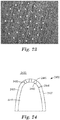
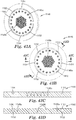
- Figs. 22 and 23 are optical micrographs of respective hole entries 182 and hole exits 183 of a cluster 192 of holes 195 made according to the processes disclosed herein.
- Fig. 25 is a scanning electron micrograph of one of the holes 195, viewed from the hole entry side. The hole has a hole entry 2510 and a hole exit 2520 that is smaller than the hole entry. The micrograph clearly illustrates a taper and a twist in the hole.
- two clusters 192 and 193 are separated along a direction 199 resulting in a first nozzle 102 and a separate, and in some cases substantially identical, second nozzle 103.
- the nozzles 102 and 103 can be used, for example, in a spray device and/or a fuel injector.
- Fig. 24 is a schematic side-view of a nozzle 2400 that includes a hollow interior 2410 and a wall 2405 separating the hollow interior from an outside 2430 of the nozzle.
- the nozzle further includes at least one hole, such as a hole 2420, that connects hollow interior 2410 to outside 2430 of the nozzle.
- the holes deliver gas or liquid from the hollow interior to the outside.
- Hole 2420 can be any hole disclosed herein.
- Hole 2420 includes a hole entry 2440 at an inner surface 2406 of wall 2405 and a hole exit 2445 at an outside surface 2407 of wall 2405.
- Hole entry 2440 is also at hollow interior 2410 of the nozzle and hole exit 2445 is at outside 2430 of the nozzle.
- hole entry 2440 has a first shape and hole exit 2445 has a second shape that is different than the first shape.
- the first shape is an elliptical shape and the second shape is a circular shape.
- the first shape can be a racetrack or oval shape and the second shape can be a circular shape.
- the second shape can be a circle or an ellipse and the perimeter of the first shape can include outer arcs of a plurality of closely packed circles, where the outer arcs are connected to each other by curve-like fillets.
- the first shape can be substantially the same as the second shape, but they can have different magnifications or sizes.
- the first shape can be a circle with a radius a 1 and the second shape can also be a circle, but with a radius a 2 different than a 1 .
- hole 2420 has a lateral cross-section that rotates from hole entry 2440 to hole exit 2445 where lateral cross-section refers to a cross-section that is substantially perpendicular to the general flow direction of, for example, a liquid or gas within the hole.
- lateral cross-section refers to a cross-section that is substantially perpendicular to the general flow direction of, for example, a liquid or gas within the hole.
- the cross-section has an increasing rotation rate from the hole entry to the hole exit.
- the cross-section has a decreasing rotation rate from the hole entry to the hole exit.
- the cross-section has a constant rotation rate from the hole entry to the hole exit.
- Rhodamine B hexafluoroantimonate was prepared by metathesis of Rhodamine B chloride with sodium hexafluoroantimonate.
- SR368 refers to tris-(2-hydroxyethyl)isocyanurate triacrylate, (obtained from Sartomer Co.
- SR9008 refers to a trifunctional acrylate ester (obtained from Sartomer); SR1012 refers to diaryliodonium hexafluoroantimonate (obtained from Sartomer); SU-8 R2150 refers to an epoxy negative photoresist (obtained from MicroChem Corp., Newton, MA); THF refers to tetrahydrofuran; LEXAN HPS1R refers to a thermoplastic polycarbonate (obtained from Sabic Innovative Plastics, Pittsfield, MA; and Inco S-Rounds refers to nickel (obtained from Vale Inco America's, Inc., Saddle Brook, NJ).
- a circular silicon wafer (substrate 110 in Fig. 1A ), 10.2 cm in diameter, was obtained from Wafer World, Inc., West Palm Beach, Florida.
- the Si wafer was cleaned by soaking it for approximately ten minutes in a 3:1 mixture by volume of concentrated sulfuric acid and 30% by weight aqueous hydrogen peroxide.
- the wafer was then rinsed with deionized water and then with isopropanol, after which it was dried under a stream of air.
- the wafer was then dipped into a two weight percent solution of 3-(trimethoxysilyl)propyl methacrylate in 190-proof ethanol that had been made acidic (pH between 4 and 5) with acetic acid.
- the wafer was then rinsed with absolute ethanol and was then heated in an oven at 130°C for ten minutes.
- Poly(methyl methacrylate), having a number average molecular weight of approximately 120,000, SR9008, and SR368 were combined in a weight ratio of 30:35:35 resulting in a monomer mixture that was dissolved in sufficient 1,2-dichloroethane to afford a solution that was 54 weight percent of the monomer mixture.
- To this solution there were then added aliquots of concentrated solutions of photosensitizer Rhodamine B hexafluoroantimonate in THF and SR1012 in THF sufficient to give a coating solution that was 0.5 weight percent Rhodamine B hexafluoroantimonate and 1.0 weight percent SR1012, based on the total weight of solids.
- This coating solution was filtered through a 1-micron syringe filter and was spin-coated onto the silicon wafer.
- the coated wafer was placed in a forced air oven at 60°C for 18 hours to afford a coated silicon wafer with a substantially solvent-free (hereinafter, "dry") coating (layer 115 of the first material in Fig. 1A ) having a thickness of approximately 300 ⁇ m.
- dry substantially solvent-free
- Two-photon polymerization of the dry coating was carried out using a diode-pumped Ti:sapphire laser (obtained from Spectra-Physics, Mountain View, CA) that operated at 800 nm with a nominal pulse width of 80 fs, a pulse repetition rate of 80 MHz, and an average power of approximately 1 W.
- the coated wafer was placed on a computer-controlled three-axis stage (obtained from Aerotech, Inc., Pittsburgh, PA).
- the laser beam was attenuated by neutral density filters and was focused into the dry coating using a galvoscanner with a telescope for x-, y-, and z-axis control (available from Nutfield Technology, Inc., Windham, NH).
- a Nikon CFI Plan Achromat 50X oil objective N.A. 0.90 with a working distance of 0.400 mm and a 4.0 mm focal length was applied directly onto the surface of the dry coating.
- the average power was measured at the output of the objective lens using a wavelength-calibrated photodiode (obtained from Ophir Optronics, Ltd., Wilmington, MA) and was determined to be approximately 8 mW.
- the surface of the first microstructured pattern was made conductive by sputtering a thin layer (about 100 angstroms) of Silver (Ag) on the surface of the pattern.
- the metalized front surface was then electroplated with Inco S-Rounds (nickel) until it was approximately 2mm thick.
- the electroplated nickel slug was then separated from the first pattern and ground and machined resulting in a first mold 140 having a second microstructured pattern 141 (Fig. IF).
- the first mold was then placed into an injection die mold which was placed into a single screw plastic injection molding system to inject thermoplastic polycarbonate (LEXAN HPS1R) into the mold cavity resulting in a second mold 160 having a third microstructured pattern 161 ( Fig. 1H ).
- thermoplastic polycarbonate LEXAN HPS1R
- the front surface of the second mold was then metalized by sputtering the surface with about 100 angstroms of silver.
- the metalized second mold was then electroplated with Inco S-Rounds (nickel) to totally cover the third microstructured pattern resulting in a nickel layer 170 ( Fig. 1J ).
- the front surface 172 ( Fig. 1J ) of the nickel layer was ground in a planar fashion to remove the nickel material from the tops 171 of the third microstructured pattern.
- the electroplated nickel layer was separated from the polycarbonate mold 160 resulting in a nickel disc, approximately 8 mm in diameter and 160 um thick having 37 through-holes arranged in a circular hexagonal packing arrangement.
- the separation between neighboring holes was about 200 ⁇ m.
- Each hole had a hole entry in the shape of a racetrack modified with fillets along the linear portions of the racetrack.
- the racetrack had a major diameter of about 80 ⁇ m and a minor diameter of about 50 ⁇ m.
- Each hole had a hole exit in the shape of a smaller racetrack with a major diameter of about 50 ⁇ m and a minor diameter of about 35 ⁇ m. Viewed from the hole exit side, the major diameters of the cross-section of the holes rotated clockwise from the hole exit to the hole entry by about 30 degrees for every 50 ⁇ m of depth below the hole exit.
- the exciting light is not attenuated by single-photon absorption within a curable matrix or material, it is possible to selectively excite molecules at a greater depth within a material than would be possible via single-photon excitation by use of a beam that is focused to that depth in the material. These two phenomena also apply, for example, to excitation within tissue or other biological materials.
- Multiphoton-initiated reactions that cause a change in solubility of a reactive material are useful in multiphoton microfabrication (also known as Two-Photon Fabrication). Such reactions may involve polymerization, crosslinking, depolymerization, or change in solubility due to reactions involving a transformation of functional groups, for example, from polar to non-polar, or non-polar to polar. Reactions are initiated by absorption of at least two-photons by a multiphoton photoinitiation system capable of undergoing simultaneous absorption of two or more photons to form free radicals and/or acid capable of initiating cationic or free radical reactions.
- Exposure of multiphoton reactive compositions to sufficient light to form an image can be accomplished by focusing a beam from an appropriate laser system (see page 22-23, this document) within the multiphoton reactive composition. Reaction occurs in the vicinity of the focal point of the focused laser beam to cause a change in solubility of the exposed composition.
- the smallest region in which reaction occurs is a three-dimensional imaging element, or voxel.
- a single voxel is the smallest feature that can be fabricated by multiphoton lithography, and can have a size that is less than the diffraction limit utilized.
- the voxel can be as small as 100 nm or less, in x, y, and z, and as large as 10 microns or larger in z and 4 microns or larger in x and y, depending on the numeric aperture of the lens used to focus the laser beam.
- the directions x, y, and z, are the axes perpendicular to the beam path (x, y), or parallel to the beam path (z).
- the voxel has at least one dimension that is less than 2 microns, preferably less than 1 micron, more preferably less than 0.5 microns,
- Reactive species suitable for use in the photoreactive compositions include both curable and non-curable species.
- Curable species are generally preferred and include, for example, addition-polymerizable monomers and oligomers and addition-crosslinkable polymers (such as free-radically polymerizable or crosslinkable ethylenically-unsaturated species including, for example, acrylates, methacrylates, and certain vinyl compounds such as styrenes), as well as cationically-polymerizable monomers and oligomers and cationically-crosslinkable polymers (which species are most commonly acid-initiated and which include, for example, epoxies, vinyl ethers, cyanate esters, etc.), and the like, and mixtures thereof.
- addition-polymerizable monomers and oligomers and addition-crosslinkable polymers such as free-radically polymerizable or crosslinkable ethylenically-unsaturated species including, for example, acrylates, me
- Suitable ethylenically-unsaturated species are described, for example, by Palazzotto et al. in U.S. Patent No. 5,545,676 at column 1, line 65, through column 2, line 26, and include mono-, di-, and poly-acrylates and methacrylates (for example, methyl acrylate, methyl methacrylate, ethyl acrylate, isopropyl methacrylate, n-hexyl acrylate, stearyl acrylate, allyl acrylate, glycerol diacrylate, glycerol triacrylate, ethyleneglycol diacrylate, diethyleneglycol diacrylate, triethyleneglycol dimethacrylate,1,3-propanediol diacrylate, 1,3-propanediol dimethacrylate, trimethylolpropane triacrylate, 1,2,4-butanetriol trimethacrylate, 1,4-cyclohexanediol diacrylate,
- Patent No. 4,652,274 and acrylated oligomers such as those of U.S. Patent No. 4, 642,126 ); unsaturated amides (for example, methylene bis-acrylamide, methylene bismethacrylamide, 1,6-hexamethylene bis-acrylamide, diethylene triamine tris-acrylamide and beta-methacrylaminoethyl methacrylate); vinyl compounds (for example, styrene, diallyl phthalate, divinyl succinate, divinyl adipate, and divinyl phthalate); and the like; and mixtures thereof.
- Suitable reactive polymers include polymers with pendant (meth)acrylate groups, for example, having from 1 to about 50 (meth)acrylate groups per polymer chain.
- polymers examples include aromatic acid (meth)acrylate half ester resins such as SarboxTM resins available from Sartomer (for example, SarboxTM 400, 401, 402, 404, and 405).
- Other useful reactive polymers curable by free radical chemistry include those polymers that have a hydrocarbyl backbone and pendant peptide groups with free-radically polymerizable functionality attached thereto, such as those described in U.S. Patent No. 5,235,015 (Ali et al. ). Mixtures of two or more monomers, oligomers, and/or reactive polymers can be used if desired.
- Preferred ethylenically-unsaturated species include acrylates, aromatic acid (meth)acrylate half ester resins, and polymers that have a hydrocarbyl backbone and pendant peptide groups with free-radically polymerizable functionality attached thereto.
- Suitable cationically-reactive species are described, for example, by Oxman et al. in U.S. Patent Nos. 5,998,495 and 6,025,406 and include epoxy resins.
- Such materials broadly called epoxides, include monomeric epoxy compounds and epoxides of the polymeric type and can be aliphatic, alicyclic, aromatic, or heterocyclic. These materials generally have, on the average, at least 1 polymerizable epoxy group per molecule (preferably, at least about 1.5 and, more preferably, at least about 2).
- the polymeric epoxides include linear polymers having terminal epoxy groups (for example, a diglycidyl ether of a polyoxyalkylene glycol), polymers having skeletal oxirane units (for example, polybutadiene polyepoxide), and polymers having pendant epoxy groups (for example, a glycidyl methacrylate polymer or copolymer).
- the epoxides can be pure compounds or can be mixtures of compounds containing one, two, or more epoxy groups per molecule.
- These epoxy-containing materials can vary greatly in the nature of their backbone and substituent groups.
- the backbone can be of any type and substituent groups thereon can be any group that does not substantially interfere with cationic cure at room temperature.
- permissible substituent groups include halogens, ester groups, ethers, sulfonate groups, siloxane groups, nitro groups, phosphate groups, and the like.
- the molecular weight of the epoxy-containing materials can vary from about 58 to about 100,000 or more.
- epoxy-containing materials that are useful include glycidyl ether monomers of the formula where R' is alkyl or aryl and n is an integer of 1 to 8.
- examples are glycidyl ethers of polyhydric phenols obtained by reacting a polyhydric phenol with an excess of a chlorohydrin such as epichlorohydrin (for example, the diglycidyl ether of 2,2-bis-(2,3-epoxypropoxyphenol)-propane). Additional examples of epoxides of this type are described in U.S. Patent No. 3,018,262 , and in Handbook of Epoxy Resins, Lee and Neville, McGraw-Hill Book Co., New York (1967 ).
- Epoxides that are readily available include, but are not limited to, octadecylene oxide; epichlorohydrin; styrene oxide; vinylcyclohexene oxide; glycidol; glycidyl methacrylate; diglycidyl ethers of bisphenol A (for example, those available as “EPON 815C”, “EPON 813", “EPON 828”, “EPON 1004F”, and "EPON 1001F” from Hexion Specialty Chemicals, Inc., Columbus, OH); and diglycidyl ether of bisphenol F (for example, those available as "ARALDITE GY281" from Ciba Specialty Chemicals Holding Company, Basel, Switzerland, and "EPON 862” from Hexion Specialty Chemicals, Inc.).
- Other aromatic epoxy resins include the SU-8 resins available from MicroChem Corp., Newton, MA.
- epoxy monomers include vinyl cyclohexene dioxide (available from SPI Supplies, West Chester, PA); 4-vinyl-1-cylcohexene diepoxide (available from Aldrich Chemical Co., Milwaukee, WI); 3,4-epoxycyclohexylmethyl-3,4-epoxycyclohexene carboxylate (for example, one available as "CYRACURE UVR-6110" from Dow Chemical Co., Midland, MI); 3,4-epoxy-6-methylcylcohexylmethyl-3,4-epoxy-6-methyl-cylcohexane carboxylate; 2-(3,4-epoxycyclohexyl-5,5-spiro-3,4-epoxy) cyclohexane-metadioxane; bis(3,4-epoxycyclohexylmethyl) adipate (for example, one available as "CYRACURE UVR-6128” from Dow Chemical Co.); bis(3,4-epoxy-6-
- Still other exemplary epoxy resins include epoxidized polybutadiene (for example, one available as "POLY BD 605E”from Sartomer Co., Inc., Exton, PA); epoxy silanes (for example, 3,4-epoxycylclohexylethyltrimethoxysilane and 3-glycidoxypropyltrimethoxysilane, commercially available from Aldrich Chemical Co., Milwaukee, WI); flame retardant epoxy monomers (for example, one available as "DER-542", a brominated bisphenol type epoxy monomer available from Dow Chemical Co., Midland, MI); 1,4-butanediol diglycidyl ether (for example, one available as "ARALDITE RD-2" from Ciba Specialty Chemicals); hydrogenated bisphenol A-epichlorohydrin based epoxy monomers (for example, one available as "EPONEX 1510" from Hexion Specialty Chemicals, Inc.); polyglycidyl ether of phenol-form
- HELOXY alkyl glycidyl ethers commercially available from Hexion Specialty Chemicals, Inc. (Columbus, OH) as “HELOXY”.
- Exemplary monomers include "HELOXY MODFIER 7" (a C 8 -C 10 alky glycidyl ether), “HELOXY MODIFIER 8” (a C 12 -C 14 alkyl glycidyl ether), “HELOXY MODIFIER 61" (butyl glycidyl ether), “HELOXY MODIFIER 62” (cresyl glycidyl ether), “HELOXY MODIFIER 65” (p-tert-butylphenyl glycidyl ether), “HELOXY MODIFIER 67” (diglycidyl ether of 1,4-butanediol), “HELOXY 68” (diglycidyl ether of neopentyl glycol), "HE
- Other useful epoxy resins comprise copolymers of acrylic acid esters of glycidol (such as glycidyl acrylate and glycidyl methacrylate) with one or more copolymerizable vinyl compounds. Examples of such copolymers are 1:1 styrene-glycidyl methacrylate and 1:1 methyl methacrylate-glycidyl acrylate.
- Other useful epoxy resins are well known and contain such epoxides as epichlorohydrins, alkylene oxides (for example, propylene oxide), styrene oxide, alkenyl oxides (for example, butadiene oxide), and glycidyl esters (for example, ethyl glycidate).
- Useful epoxy-functional polymers include epoxy-functional silicones such as those described in U.S. Patent No. 4,279,717 (Eckberg et al. ), which are commercially available from the General Electric Company. These are polydimethylsiloxanes in which 1-20 mole % of the silicon atoms have been substituted with epoxyalkyl groups (preferably, epoxy cyclohexylethyl, as described in U.S. Patent No. 5,753,346 (Leir et al. ).
- Blends of various epoxy-containing materials can also be utilized. Such blends can comprise two or more weight average molecular weight distributions of epoxy-containing compounds (such as low molecular weight (below 200), intermediate molecular weight (about 200 to 1000), and higher molecular weight (above about 1000)).
- the epoxy resin can contain a blend of epoxy-containing materials having different chemical natures (such as aliphatic and aromatic) or functionalities (such as polar and non-polar).
- Other cationically-reactive polymers such as vinyl ethers and the like) can additionally be incorporated, if desired.
- Preferred epoxies include aromatic glycidyl epoxies (for example, the EPON resins available from Hexion Specialty Chemicals, Inc. and the SU-8 resins available from MicroChem Corp., Newton, MA), and the like, and mixtures thereof. More preferred are the SU-8 resins and mixtures thereof.
- Suitable cationically-reactive species also include vinyl ether monomers, oligomers, and reactive polymers (for example, methyl vinyl ether, ethyl vinyl ether, tert-butyl vinyl ether, isobutyl vinyl ether, triethyleneglycol divinyl ether (RAPI-CURE DVE-3, available from International Specialty Products, Wayne, NJ), trimethylolpropane trivinyl ether, and the VECTOMER divinyl ether resins from Morflex, Inc., Greensboro, NC (for example, VECTOMER 1312, VECTOMER 4010, VECTOMER 4051, and VECTOMER 4060 and their equivalents available from other manufacturers)), and mixtures thereof.
- VECTOMER divinyl ether resins from Morflex, Inc., Greensboro, NC (for example, VECTOMER 1312, VECTOMER 4010, VECTOMER 4051, and VECTOMER 4060 and their equivalents available from other manufacturers)
- Blends in any proportion) of one or more vinyl ether resins and/or one or more epoxy resins can also be utilized.
- Polyhydroxy-functional materials such as those described, for example, in U.S. Patent No. 5,856,373 (Kaisaki et al. ) can also be utilized in combination with epoxy- and/or vinyl ether-functional materials.
- Non-curable species include, for example, reactive polymers whose solubility can be increased upon acid- or radical-induced reaction.
- reactive polymers include, for example, aqueous insoluble polymers bearing ester groups that can be converted by photogenerated acid to aqueous soluble acid groups (for example, poly(4-tert-butoxycarbonyloxystyrene).
- Non-curable species also include the chemically-amplified photoresists described by R. D. Allen et al. in "High Performance Acrylic Polymers for Chemically Amplified Photoresist Applications," J. Vac. Sci. Technol. B, 9, 3357 (1991 ).
- THP tetrahydropyran
- THP-phenolic materials such as those described in U.S. Patent No. 3,779,778
- t-butyl methacrylate-based materials such as those described by R. D Allen et al. in Proc. SPIE 2438, 474 (1995 ), and the like
- depolymerization for example, polyphthalaldehyde-based materials
- rearrangement for example, materials based on the pinacol rearrangements.
- mixtures of different types of reactive species can be utilized in the photoreactive compositions.
- mixtures of free-radically-reactive species and cationically-reactive species are also useful.
- the photoinitiator system is a multiphoton photoinitiator system, as the use of such a system enables reaction to be confined or limited to the focal region of a focused beam of light.
- a system preferably is a two- or three-component system that comprises at least one multiphoton photosensitizer, at least one photoinitiator (or electron acceptor), and, optionally, at least one electron donor.
- Such multi-component systems can provide enhanced sensitivity, enabling photoreaction to be effected in a shorter period of time and thereby reducing the likelihood of problems due to movement of the sample and/or one or more components of the exposure system.
- the multiphoton photoinitiator system comprises photochemically effective amounts of (a) at least one multiphoton photosensitizer that is capable of simultaneously absorbing at least two photons and that, optionally but preferably, has a two-photon absorption cross-section greater than that of fluorescein; (b) optionally, at least one electron donor compound different from the multiphoton photosensitizer and capable of donating an electron to an electronic excited state of the photosensitizer; and (c) at least one photoinitiator that is capable of being photosensitized by accepting an electron from an electronic excited state of the photosensitizer, resulting in the formation of at least one free radical and/or acid.
- the multiphoton photoinitiator system can be a one-component system that comprises at least one photoinitiator.
- Photoinitiators useful as one-component multi-photon photoinitiator systems include acyl phosphine oxides (for example, those sold by Ciba under the trade name IrgacureTM 819, as well as 2,4,6 trimethyl benzoyl ethoxyphenyl phosphine oxide sold by BASF Corporation under the trade name LucirinTM TPO-L) and stilbene derivatives with covalently attached sulfonium salt moieties (for example, those described by W. Zhou et al. in Science 296, 1106 (2002 )).
- Other conventional ultraviolet (UV) photoinitiators such as benzil ketal can also be utilized, although their multi-photon photoinitiation sensitivities will generally be relatively low.
- Multiphoton photosensitizers, electron donors, and photoinitiators (or electron acceptors) useful in two- and three-component multiphoton photoinitiator systems are described below.
- Multiphoton photosensitizers suitable for use in the multiphoton photoinitiator system of the photoreactive compositions are those that are capable of simultaneously absorbing at least two photons when exposed to sufficient light.
- the photosensitizers have a two-photon absorption cross-section greater than that of fluorescein (that is, greater than that of 3', 6'- dihydroxyspiro[isobenzofuran-1(3H), 9'-[9H]xanthen]3-one).
- the preferred cross-section can be greater than about 50 x 10 -50 cm 4 sec/photon, as measured by the method described by C. Xu and W. W. Webb in J. Opt. Soc. Am. B, 13, 481 (1996 ) (which is referenced by Marder and Perry et al. in International Publication No. WO 98/21521 at page 85, lines 18-22).
- the two-photon absorption cross-section of the photosensitizer is greater than about 1.5 times that of fluorescein (or greater than about 75 x 10 -50 cm 4 sec/photon, as measured by the above method); even more preferably, greater than about twice that of fluorescein (or greater than about 100 x 10 -50 cm 4 sec/photon); most preferably, greater than about three times that of fluorescein (or, alternatively, greater than about 150 x 10 -50 cm 4 sec/photon); and optimally, greater than about four times that of fluorescein (or, alternatively, greater than about 200 x 10 -50 cm 4 sec/photon).
- the photosensitizer is soluble in the reactive species (if the reactive species is liquid) or is compatible with the reactive species and with any binders (as described below) that are included in the composition.
- the photosensitizer is also capable of sensitizing 2-methyl-4,6-bis(trichloromethyl)-s-triazine under continuous irradiation in a wavelength range that overlaps the single photon absorption spectrum of the photosensitizer (single photon absorption conditions), using the test procedure described in U.S. Pat. No. 3,729,313 .
- a photosensitizer can also be selected based in part upon shelf stability considerations. Accordingly, selection of a particular photosensitizer can depend to some extent upon the particular reactive species utilized (as well as upon the choices of electron donor compound and/or photoinitiator).
- Particularly preferred multiphoton photosensitizers include those exhibiting large multiphoton absorption cross-sections, such as Rhodamine B (that is, N-[9-(2-carboxyphenyl)-6-(diethylamino)-3H-xanthen-3-ylidene]-N-ethylethanaminium chloride or hexafluoroantimonate) and the four classes of photosensitizers described, for example, by Marder and Perry et al. in International Patent Publication Nos. WO 98/21521 and WO 99/53242 .
- the four classes can be described as follows: (a) molecules in which two donors are connected to a conjugated ⁇ (pi)-electron bridge; (b) molecules in which two donors are connected to a conjugated ⁇ (pi)-electron bridge which is substituted with one or more electron accepting groups; (c) molecules in which two acceptors are connected to a conjugated ⁇ (pi)-electron bridge; and (d) molecules in which two acceptors are connected to a conjugated ⁇ (pi)-electron bridge which is substituted with one or more electron donating groups (where "bridge” means a molecular fragment that connects two or more chemical groups, “donor” means an atom or group of atoms with a low ionization potential that can be bonded to a conjugated ⁇ (pi)-electron bridge, and "acceptor” means an atom or group of atoms with a high electron affinity that can be bonded to a conjugated ⁇ (pi)-electron bridge).
- the four above-described classes of photosensitizers can be prepared by reacting aldehydes with ylides under standard Wittig conditions or by using the McMurray reaction, as detailed in International Patent Publication No. WO 98/21521 .
- Preferred photosensitizers include the following compounds (and mixtures thereof):
- Electron donor compounds useful in the multiphoton photoinitiator system of the photoreactive compositions are those compounds (other than the photosensitizer itself) that are capable of donating an electron to an electronic excited state of the photosensitizer. Such compounds may be used, optionally, to increase the multiphoton photosensitivity of the photoinitiator system, thereby reducing the exposure required to effect photoreaction of the photoreactive composition.
- the electron donor compounds preferably have an oxidation potential that is greater than zero and less than or equal to that of p-dimethoxybenzene. Preferably, the oxidation potential is between about 0.3 and 1 volt vs. a standard saturated calomel electrode ("S.C.E.”).
- the electron donor compound is also preferably soluble in the reactive species and is selected based in part upon shelf stability considerations (as described above). Suitable donors are generally capable of increasing the speed of cure or the image density of a photoreactive composition upon exposure to light of the desired wavelength.
- electron donor compounds suitable for use with particular photosensitizers and photoinitiators can be selected by comparing the oxidation and reduction potentials of the three components (as described, for example, in U.S. Patent No. 4,859,572 (Farid et al. )).
- Such potentials can be measured experimentally (for example, by the methods described by R. J. Cox, Photographic Sensitivity, Chapter 15, Academic Press (1973 )) or can be obtained from references such as N. L. Weinburg, Ed., Technique of Electroorganic Synthesis Part II Techniques of Chemistry, Vol. V (1975 ), and C. K. Mann and K. K. Barnes, Electrochemical Reactions in Nonaqueous Systems (1970 ).
- the potentials reflect relative energy relationships and can be used to guide electron donor compound selection.
- Suitable electron donor compounds include, for example, those described by D. F. Eaton in Advances in Photochemistry, edited by B. Voman et al., Volume 13, pp. 427-488, John Wiley and Sons, New York (1986 ); by Oxman et al. in U.S. Patent No. 6,025,406 at column 7, lines 42-61; and by Palazzotto et al. in U.S. Patent No. 5, 545,676 at column 4, line 14 through column 5, line 18.
- the electron donor compound can be unsubstituted or can be substituted with one or more non-interfering substituents.
- Particularly preferred electron donor compounds contain an electron donor atom (such as a nitrogen, oxygen, phosphorus, or sulfur atom) and an abstractable hydrogen atom bonded to a carbon or silicon atom alpha to the electron donor atom.
- Preferred amine electron donor compounds include alkyl-, aryl-, alkaryl- and aralkyl-amines (for example, methylamine, ethylamine, propylamine, butylamine, triethanolamine, amylamine, hexylamine, 2,4-dimethylaniline, 2,3-dimethylaniline, o-, m- and p-toluidine, benzylamine, aminopyridine, N,N'-dimethylethylenediamine, N,N'-diethylethylenediamine, N,N'-dibenzylethylenediamine, N,N'-diethyl-1,3-propanediamine, N,N'-diethyl-2-butene-1,4-diamine, N,N'-dimethyl-1,6-hexanediamine, piperazine, 4,4'-trimethylenedipiperidine, 4,4'-ethylenedipiperidine, p-N,N-dimethyl-a
- Tertiary aromatic alkylamines particularly those having at least one electron-withdrawing group on the aromatic ring, have been found to provide especially good shelf stability. Good shelf stability has also been obtained using amines that are solids at room temperature. Good photosensitivity has been obtained using amines that contain one or more julolidinyl moieties.
- Preferred amide electron donor compounds include N,N-dimethylacetamide, N,N-diethylacetamide, N-methyl-N-phenylacetamide, hexamethylphosphoramide, hexaethylphosphoramide, hexapropylphosphoramide, trimorpholinophosphine oxide, tripiperidinophosphine oxide, and mixtures thereof.
- Preferred alkylarylborate salts include Ar 3 B - (n-C 4 H 9 )N + (C 2 H 5 ) 4 Ar 3 B - (n-C 4 H 9 )N + (CH 3 ) 4 Ar 3 B - (n-C 4 H 9 )N + (n-C 4 H 9 ) 4 Ar 3 B - (n-C 4 H 9 )Li + Ar 3 B - (n-C 4 H 9 )N + (C 6 H 13 ) 4 Ar 3 B - -(C 4 H 9 )N + (CH 3 ) 3 (CH 2 ) 2 CO 2 (CH 2 ) 2 CH 3 Ar 3 B - -(C 4 H 9 )N + (CH 3 ) 3 (CH 2 ) 2 OCO(CH 2 ) 2 CH 3 Ar 3 B - -(sec-C 4 H 9 )N + (CH 3 ) 3 (CH 2 ) 2 CO 2 (CH 2 ) 2 CH 3 Ar 3 B - -(sec-C 4 H 9
- Suitable ether electron donor compounds include 4,4'-dimethoxybiphenyl, 1,2,4-trimethoxybenzene, 1,2,4,5-tetramethoxybenzene, and the like, and mixtures thereof.
- Suitable urea electron donor compounds include N,N'-dimethylurea, N,N-dimethylurea, N,N'-diphenylurea, tetramethylthiourea, tetraethylthiourea, tetra-n-butylthiourea, N,N-di-n-butylthiourea, N,N'-di-n-butylthiourea, N,N-diphenylthiourea, N,N'-diphenyl-N,N'-diethylthiourea, and the like, and mixtures thereof.
- Preferred electron donor compounds for free radical-induced reactions include amines that contain one or more julolidinyl moieties, alkylarylborate salts, and salts of aromatic sulfinic acids.
- the electron donor compound can also be omitted, if desired (for example, to improve the shelf stability of the photoreactive composition or to modify resolution, contrast, and reciprocity).
- Preferred electron donor compounds for acid-induced reactions include 4-dimethylaminobenzoic acid, ethyl 4-dimethylaminobenzoate, 3-dimethylaminobenzoic acid, 4-dimethylaminobenzoin, 4-dimethylaminobenzaldehyde, 4-dimethylaminobenzonitrile, 4-dimethylaminophenethyl alcohol, and 1,2,4-trimethoxybenzene.
- Suitable photoinitiators for the reactive species of the photoreactive compositions are those that are capable of being photosensitized by accepting an electron from an electronic excited state of the multiphoton photosensitizer, resulting in the formation of at least one free radical and/or acid.
- Such photoinitiators include iodonium salts (for example, diaryliodonium salts), sulfonium salts (for example, triarylsulfonium salts optionally substituted with alkyl or alkoxy groups, and optionally having 2,2' oxy groups bridging adjacent aryl moieties), and the like, and mixtures thereof.
- the photoinitiator is preferably soluble in the reactive species and is preferably shelf-stable (that is, does not spontaneously promote reaction of the reactive species when dissolved therein in the presence of the photosensitizer and the electron donor compound). Accordingly, selection of a particular photoinitiator can depend to some extent upon the particular reactive species, photosensitizer, and electron donor compound chosen, as described above. If the reactive species is capable of undergoing an acid-initiated chemical reaction, then the photoinitiator is an onium salt (for example, an iodonium or sulfonium salt).
- Suitable iodonium salts include those described by Palazzotto et al. in U.S. Patent No. 5,545,676 at column 2, lines 28 through 46. Suitable iodonium salts are also described in U.S. Patent Nos. 3,729,313 , 3,741,769 , 3,808,006 , 4,250,053 and 4,394,403 .
- the iodonium salt can be a simple salt (for example, containing an anion such as Cl - , Br - , I - or C 4 H 5 SO 3 - ) or a metal complex salt (for example, containing SbF 6 - , PF 6 - , BF 4 - , tetrakis(perfluorophenyl)borate, SbF 5 OH - or AsF 6 - ). Mixtures of iodonium salts can be used if desired.
- aromatic iodonium complex salt photoinitiators examples include diphenyliodonium tetrafluoroborate; di(4-methylphenyl)iodonium tetrafluoroborate; phenyl-4-methylphenyliodonium tetrafluoroborate; di(4-heptylphenyl)iodonium tetrafluoroborate; di(3-nitrophenyl)iodonium hexafluorophosphate; di(4-chlorophenyl)iodonium hexafluorophosphate; di(naphthyl)iodonium tetrafluoroborate; di(4-trifluoromethylphenyl)iodonium tetrafluoroborate; diphenyliodonium hexafluorophosphate; di(4-methylphenyl)iodonium hexafluorophosphate; diphenyliodonium hexafluor
- Aromatic iodonium complex salts can be prepared by metathesis of corresponding aromatic iodonium simple salts (such as, for example, diphenyliodonium bisulfate) in accordance with the teachings of Beringer et al., J. Am. Chem. Soc. 81, 342 (1959 ).
- Preferred iodonium salts include diphenyliodonium salts (such as diphenyliodonium chloride, diphenyliodonium hexafluorophosphate, and diphenyliodonium tetrafluoroborate), diaryliodonium hexafluoroantimonate (for example, SarCatTM SR 1012 available from Sartomer Company), and mixtures thereof.
- diphenyliodonium salts such as diphenyliodonium chloride, diphenyliodonium hexafluorophosphate, and diphenyliodonium tetrafluoroborate
- diaryliodonium hexafluoroantimonate for example, SarCatTM SR 1012 available from Sartomer Company
- Useful sulfonium salts include those described in U.S. Patent No. 4,250,053 (Smith ) at column 1, line 66, through column 4, line 2, which can be represented by the formulas: wherein R 1 , R 2 , and R 3 are each independently selected from aromatic groups having from about 4 to about 20 carbon atoms (for example, substituted or unsubstituted phenyl, naphthyl, thienyl, and furanyl, where substitution can be with such groups as alkoxy, alkylthio, arylthio, halogen, and so forth) and alkyl groups having from 1 to about 20 carbon atoms.
- alkyl includes substituted alkyl (for example, substituted with such groups as halogen, hydroxy, alkoxy, or aryl). At least one of R 1 , R 2 , and R 3 is aromatic, and, preferably, each is independently aromatic.
- X - is an anion, as described below.
- Suitable anions, X - , for the sulfonium salts (and for any of the other types of photoinitiators) include a variety of anion types such as, for example, imide, methide, boron-centered, phosphorous-centered, antimony-centered, arsenic-centered, and aluminum-centered anions.
- Suitable imide and methide anions include (C 2 F 5 SO 2 ) 2 N - , (C 4 F 9 SO 2 ) 2 N - , (C 8 F 17 SO 2 ) 3 C - , (CF 3 SO 2 ) 3 C - , (CF 3 SO 2 ) 2 N - , (C 4 F 9 SO 2 ) 3 C - , (CF 3 SO 2 ) 2 (C 4 F 9 SO 2 )C - , (CF 3 SO 2 )(C 4 F 9 SO 2 )N - , ((CF 3 ) 2 NC 2 F 4 SO 2 ) 2 N - , (CF 3 ) 2 NC 2 F 4 SO 2 C - (SO 2 CF 3 ) 2 , (3,5-bis(CF 3 )C 6 H 3 )SO 2 N - SO 2 CF 3 , C 6 H 5 SO 2 C - (SO 2 CF 3 ) 2 , C 6 H 5 SO 2 N -
- boron-centered anions include F 4 B - , (3,5-bis(CF 3 )C 6 H 3 ) 4 B - , (C 6 F 5 ) 4 B - , (p-CF 3 C 6 H 4 ) 4 B - , (m-CF 3 C 6 H 4 ) 4 B - , (p-FC 6 H 4 ) 4 B - , (C 6 F 5 ) 3 (CH 3 )B - , (C 6 F 5 ) 3 (n-C 4 H 9 )B - , (p-CH 3 C 6 H 4 ) 3 (C 6 F 5 )B-, (C 6 F 5 ) 3 FB - , (C 6 H 5 ) 3 (C 6 F 5 )B - , (CH 3 ) 2 (p-CF 3 C 6 H 4 ) 2 B - , (C 6 F 5 ) 3 (n-C 18 H 37 O)B - , and the
- Preferred boron-centered anions generally contain 3 or more halogen-substituted aromatic hydrocarbon radicals attached to boron, with fluorine being the most preferred halogen.
- Illustrative, but not limiting, examples of the preferred anions include (3,5-bis(CF 3 )C 6 H 3 ) 4 B - , (C 6 F 5 ) 4 B - , (C 6 F 5 ) 3 (n-C 4 H 9 )B - , (C 6 F 5 ) 3 FB - , and (C 6 F 5 ) 3 (CH 3 )B - .
- Suitable anions containing other metal or metalloid centers include, for example, (3,5-bis(CF 3 )C 6 H 3 ) 4 Al - , (C 6 F 5 ) 4 Al - , (C 6 F 5 ) 2 F 4 P - , (C 6 F 5 )F 5 P - , F 6 P - , (C 6 F 5 )F S Sb - , F 6 Sb - , (HO)F 5 Sb - , and F 6 As - .
- the anion, X - is selected from tetrafluoroborate, hexafluorophosphate, hexafluoroarsenate, hexafluoroantimonate, and hydroxypentafluoroantimonate (for example, for use with cationically-reactive species such as epoxy resins).
- Suitable sulfonium salt photoinitiators include:
- Preferred sulfonium salts include triaryl-substituted salts such as triarylsulfonium hexafluoroantimonate (for example, SarCatTM SR1010 available from Sartomer Company), triarylsulfonium hexafluorophosphate (for example, SarCatTM SR 1011 available from Sartomer Company), and triarylsulfonium hexafluorophosphate (for example, SarCatTM KI85 available from Sartomer Company).
- triarylsulfonium hexafluoroantimonate for example, SarCatTM SR1010 available from Sartomer Company
- triarylsulfonium hexafluorophosphate for example, SarCatTM SR 1011 available from Sartomer Company
- triarylsulfonium hexafluorophosphate for example, SarCatTM KI85 available from Sartomer Company
- Preferred photoinitiators include iodonium salts (more preferably, aryliodonium salts), sulfonium salts, and mixtures thereof. More preferred are aryliodonium salts and mixtures thereof.
- the reactive species, multiphoton photosensitizers, electron donor compounds, and photoinitiators can be prepared by the methods described above or by other methods known in the art, and many are commercially available. These four components can be combined under "safe light” conditions using any order and manner of combination (optionally, with stirring or agitation), although it is sometimes preferable (from a shelf life and thermal stability standpoint) to add the photoinitiator last (and after any heating step that is optionally used to facilitate dissolution of other components).
- Solvent can be used, if desired, provided that the solvent is chosen so as to not react appreciably with the components of the composition. Suitable solvents include, for example, acetone, dichloromethane, and acetonitrile.
- the reactive species itself can also sometimes serve as a solvent for the other components.
- the composition can contain at least about 5% (preferably, at least about 10%; more preferably, at least about 20%) up to about 99.79% (preferably, up to about 95%; more preferably, up to about 80%) by weight of one or more reactive species; at least about 0.01% (preferably, at least about 0.1%; more preferably, at least about 0.2%) up to about 10% (preferably, up to about 5%; more preferably, up to about 2%) by weight of one or more photosensitizers; optionally, up to about 10% (preferably, up to about 5%) by weight of one or more electron donor compounds (preferably, at least about 0.1%; more preferably, from about 0.1% to about 5%); and from about 0.1% to about 10% by weight of one or more electron acceptor compounds (preferably, from about 0.1% to about 5%) based upon the total weight of solids (that is, the total weight of components other than solvent).
- adjuvants can be included in the photoreactive compositions, depending upon the desired end use. Suitable adjuvants include solvents, diluents, resins, binders, plasticizers, pigments, dyes, inorganic or organic reinforcing or extending fillers (at preferred amounts of about 10% to 90% by weight based on the total weight of the composition), thixotropic agents, indicators, inhibitors, stabilizers, ultraviolet absorbers, and the like. The amounts and types of such adjuvants and their manner of addition to the compositions will be familiar to those skilled in the art.
- nonreactive polymeric binders in the compositions in order, for example, to control viscosity and to provide film-forming properties.
- Such polymeric binders can generally be chosen to be compatible with the reactive species.
- polymeric binders that are soluble in the same solvent that is used for the reactive species, and that are free of functional groups that can adversely affect the course of reaction of the reactive species can be utilized.
- Binders can be of a molecular weight suitable to achieve desired film-forming properties and solution rheology (for example, molecular weights between about 5,000 and 1,000,000 Daltons; preferably between about 10,000 and 500,000 Daltons; more preferably, between about 15,000 and 250,000 Daltons).
- Suitable polymeric binders include, for example, polystyrene, poly(methyl methacrylate), poly(styrene)-co-(acrylonitrile), cellulose acetate butyrate, and the like.
- the resulting photoreactive compositions can be coated on a substrate, if desired, by any of a variety of coating methods known to those skilled in the art (including, for example, knife coating and spin coating).
- the substrate can be chosen from a wide variety of films, sheets, and other surfaces (including silicon wafers and glass plates), depending upon the particular application and the method of exposure to be utilized.
- Preferred substrates are generally sufficiently flat to enable the preparation of a layer of photoreactive composition having a uniform thickness.
- the photoreactive compositions can alternatively be exposed in bulk form.
- a photoreactive composition can be exposed to light under conditions such that multiphoton absorption occurs, thereby causing a region of differential solubility characteristics (for example, lesser or greater solubility in a particular solvent) as compared to the photoreactive composition prior to exposure.
- Such exposure can be accomplished by any known means capable of achieving sufficient intensity of the light.
- One exemplary type of fabrication system that can be used includes a light source, an optical system comprising a final optical element (optionally including galvo-mirrors and a telescope to control beam divergence), and a moveable stage.
- the stage 16 is moveable in one, two, or, more typically, three dimensions.
- a substrate mounted on the stage has a layer of photoreactive composition thereon.
- a light beam originating from the light source passes through the optical system and leaves through the final optical element, which focuses it to a point P within the layer, thereby controlling the three-dimensional spatial distribution of light intensity within the composition and causing at least a portion of the photoreactive composition in the vicinity of point P to become more, or less, soluble in at least one solvent than it was immediately prior to exposure to the light beam.
- the portion of photoreactive composition exposed in the vicinity of point P causing a change in solubility is a three-dimensional imaging element, or voxel.
- the focal point P can be scanned or translated in a three-dimensional pattern that corresponds to a desired shape.
- the resulting reacted or partially reacted portion of the photoreactive composition then creates a three-dimensional structure of the desired shape.
- the surface profile corresponding to a thickness of about one volume pixel or voxel
- the surface profile of one or more hole forming features of a micronozzle mold pattern can be exposed or imaged, which upon development can be in the form of one or more nozzle hole forming features used to make a mold pattern of one or an array of micronozzles.
- the exposure or imaging of the surface profile of the micronozzle mold pattern can be carried out by scanning at least the perimeter of a planar slice of a desired three-dimensional structure and then scanning a plurality of preferably parallel, planar slices to complete the structure.
- Slice thickness can be controlled to achieve a sufficiently high resolution for the shape of each nozzle hole forming feature. For example, smaller slice thicknesses can be desirable in regions of greater structure taper to aid in achieving high structure fidelity, but larger slice thicknesses can be utilized in regions of less structure taper to aid in maintaining useful fabrication times.
- the light source can be any light source that produces sufficient light intensity to effect multiphoton absorption.
- Suitable sources include, for example, femtosecond near-infrared titanium sapphire oscillators (for example, those available from Coherent, Santa Clara, California, as "MIRA OPTIMA 900-F") pumped by an argon ion laser (for example, those available from Coherent as "INNOVA").
- This laser operating at 76 MHz, has a pulse width of less than 200 femtoseconds, is tunable between 700 and 980 nm, and has average power up to 1.4 Watts.
- MAI TAI tunable to wavelengths in a range of from 750 to 850 nanometers, and having a repetition frequency of 80 megahertz, and a pulse width of about 100 femtoseconds (1x10 -13 sec), with an average power level up to 1 Watt.
- any light source for example, a laser
- a wavelength appropriate for the multiphoton absorber used in the photoreactive composition can generally be in the range of about 300 to about 1500 nm; preferably, from about 400 to about 1100 nm; more preferably, from about 600 to about 900 nm; more preferably, from about 750 to about 850 nm, inclusive.
- the light fluence (for example, peak intensity of a pulsed laser) is greater than about 10 6 W/cm 2 .
- the upper limit on the light fluence is generally dictated by the ablation threshold of the photoreactive composition.
- Q-switched Nd:YAG lasers for example, those available from Spectra-Physics as "QUANTA-RAY PRO"
- visible wavelength dye lasers for example, those available from Spectra-Physics as "SIRAH” pumped by a Q-switched Nd:YAG laser from Spectra-Physics having the trade designation "Quanta-Ray PRO”
- Q-switched diode pumped lasers for example, those available from Spectra-Physics as "FCBAR
- Preferred light sources are near infrared pulsed lasers having a pulse length less than about 10 -8 second (more preferably, less than about 10 -9 second; most preferably, less than about 10 -11 second). Other pulse lengths can be used as long as the peak intensity and ablation threshold criteria above are met. Pulsed radiation can, for example, have a pulse frequency of from about one kilohertz up to about 50 megahertz, or even more. Continuous wave lasers can also be used.
- the optical system can include, for example, refractive optical elements (for example, lenses or microlens arrays), reflective optical elements (for example, retroreflectors or focusing mirrors), diffractive optical elements (for example, gratings, phase masks, and holograms), polarizing optical elements (for example, linear polarizers and waveplates), dispersive optical elements (for example, prisms and gratings), diffusers, Pockels cells, waveguides, and the like.
- refractive optical elements for example, lenses or microlens arrays
- reflective optical elements for example, retroreflectors or focusing mirrors
- diffractive optical elements for example, gratings, phase masks, and holograms
- polarizing optical elements for example, linear polarizers and waveplates
- dispersive optical elements for example, prisms and gratings
- diffusers for example, Pockels cells, waveguides, and the like.
- Such optical elements are useful for focusing, beam delivery
- the final optical element can include, for example, one or more refractive, reflective, and/or diffractive optical elements.
- an objective such as, for example, those used in microscopy can be conveniently obtained from commercial sources such as, for example, Carl Zeiss, North America, Thornwood, New York, and used as the final optical element.
- the fabrication system can include a scanning confocal microscope (for example, those available from Bio-Rad Laboratories, Hercules, California, as "MRC600") equipped with a 0.75 numerical aperture (NA) objective (such as, for example, those available from Carl Zeiss, North America as "20X FLUAR").
- Exposure times generally depend upon the type of exposure system used to cause reaction of the reactive species in the photoreactive composition (and its accompanying variables such as numerical aperture, geometry of light intensity spatial distribution, the peak light intensity during the laser pulse (higher intensity and shorter pulse duration roughly correspond to peak light intensity)), as well as upon the nature of the photoreactive composition. Generally, higher peak light intensity in the regions of focus allows shorter exposure times, everything else being equal.
- Linear imaging or "writing" speeds generally can be about 5 to 100,000 microns/second using a laser pulse duration of about 10 -8 to 10 -15 second (for example, about 10 -11 to 10 -14 second) and about 10 2 to 10 9 pulses per second (for example, about 10 3 to 10 8 pulses per second).
- a threshold dose of light (that is, threshold dose) can be utilized.
- This threshold dose is typically process specific, and can depend on variables such as, for example, the wavelength, pulse frequency, intensity of the light, the specific photoreactive composition, the specific micronozzle mold pattern structure being fabricated, or the process used for solvent development.
- each set of process parameters can typically be characterized by a threshold dose. Higher doses of light than the threshold can be used, and can be beneficial, but higher doses (once above the threshold dose) can typically be used with a slower writing speed and/or higher light intensity.
- a light dose that is less than about 10 times the threshold dose, preferably less than about 4 times the threshold dose, and more preferably less than about 3 times the threshold dose.
- the radial intensity profile of the light beam is preferably Gaussian.
- the light beam induces a reaction in the photoreactive composition that produces a volume region of material having solubility characteristics different from those of the unexposed photoreactive composition.
- the resulting pattern of differential solubility can then be realized by a conventional development process, for example, by removing either exposed or unexposed regions.
- the exposed photoreactive composition can be developed, for example, by placing the exposed photoreactive composition into solvent to dissolve regions of higher solvent solubility, by rinsing with solvent, by evaporation, by oxygen plasma etching, by other known methods, and by combinations thereof.
- Solvents that can be used for developing the exposed photoreactive composition include aqueous solvents such as, for example, water (for example, having a pH in a range of from 1 to 12) and miscible blends of water with organic solvents (for example, methanol, ethanol, propanol, acetone, acetonitrile, dimethylformamide, N-methylpyrrolidone, and the like, and mixtures thereof); and organic solvents.
- Exemplary useful organic solvents include alcohols (for example, methanol, ethanol, and propanol), ketones (for example, acetone, cyclopentanone, and methyl ethyl ketone), aromatics (for example, toluene), halocarbons (for example, methylene chloride and chloroform), nitriles (for example, acetonitrile), esters (for example, ethyl acetate and propylene glycol methyl ether acetate), ethers (for example, diethyl ether and tetrahydrofuran), amides (for example, N-methylpyrrolidone), and the like, and mixtures thereof.
- alcohols for example, methanol, ethanol, and propanol
- ketones for example, acetone, cyclopentanone, and methyl ethyl ketone
- aromatics for example, toluene
- halocarbons for example, methylene chloride and
- An optional bake after exposure to light under multiphoton absorption conditions, but prior to solvent development, can be useful for some photoreactive compositions such as, for example, epoxy-type reactive species.
- Typical bake conditions include temperatures in a range of from about 40 °C to about 200 °C, for times in a range of from about 0.5 minutes to about 20 minutes.
- a nonimagewise exposure using actinic radiation can be carried out to effect reaction of the remaining unreacted photoreactive composition.
- Such a nonimagewise exposure can preferably be carried out by using a one-photon process.
- Complex three-dimensional micronozzles and micronozzle arrays can be prepared in this manner.
- a nozzle hole forming feature or microstructure includes a circular base 806, along with a curved side 804 and planar control cavity forming feature 800 configured to form a circular-shaped hole outlet, as indicated by the shape of its microstructure top 802.
- a nozzle hole forming feature or microstructure includes a circular base 814, along with a curved side 812 and planar control cavity forming feature 808 configured to form a circular-shape hole outlet, as indicated by the shape of its microstructure top 810.
- the curved side 812 includes a set of first annular fluid flow disruption features in the form of multiple circumferential grooves 816 that are spaced apart, parallel to each other and start about midway between the base 814 and the top 810.
- a second set of such features 818 are disposed adjacent to one another and formed next to the base 814.
- a fluid flow disruption feature is a feature that causes, when imparted to the inside surface of the nozzle through-hole, disruption of the fluid flowing through the nozzle through-hole.
- Such features can include, e.g., features that cause or induce any one or combination of (a) cavitations, (b) turbulence, (c) pressure waves in the fluid flowing through the nozzle through-hole and that results in changes to the fluid flowing beyond the nozzle hole outlet.
- the nozzle hole forming microstructure of Fig. 29 includes a circular base 836, along with a curved side 834 and planar control cavity forming feature 830 configured to form a circular-shape hole outlet, as indicated by the shape of its microstructure top 832.
- the curved side 834 is configured so as to include dual or multiple converging/diverging fluid flow features that cause the fluid flowing through the corresponding nozzle through-hole to converge and diverge multiple times before exiting through the hole outlet.
- the nozzle hole forming microstructure of Fig. 30 likewise includes a circular base 844, along with a curved side 842 and planar control cavity forming feature 838 configured to form a circular-shape hole outlet, as indicated by the shape of its microstructure top 840.
- the curved side 842 is similarly structured as in the Fig. 29 embodiment, but with a single converging/diverging fluid flow feature that causes the fluid flowing through the nozzle through-hole to converge and diverge one time before exiting through the hole
- an alternative nozzle hole forming microstructure includes a circular base 852, along with a curvilinear side 850 and planar control cavity forming feature 846 configured to form a star-shape hole outlet, as indicated by the star-shape of its microstructure top 848.
- Fig. 31B shows the microstructure of Fig. 31A with its planar control cavity forming feature 846 removed to show the star-shape expected for the corresponding hole outlet.
- the star-shape top 848, and therefore the corresponding hole outlet is defined by a plurality of rectangular shaped slots or branches 848b extending out from a core 848a like the spokes of a wheel. Five rectangular-shaped slots 848b are illustrated, but other branch shapes and a different number of branches may be desirable.
- the side 850 includes a curved section 850a and a linear section 850b for each of the branches 848b.
- the nozzle hole forming microstructure of Figs. 32A and 32B includes a circular base 860, with a curvilinear side 858 and planar control cavity forming feature 854 configured to form a cross- or X-shape hole outlet, as indicated by the shape of its microstructure top 880.
- Fig. 32B shows the microstructure of Fig. 32A with its planar control cavity forming feature 854 removed to show the shape expected for the corresponding hole outlet.
- the top 856, and therefore the corresponding hole outlet is defined by four rectangular shaped slots or branches 856b extending out from a core 856a like the spokes of a wheel.
- the side 858 includes a curved section 858a and a linear section 858b for each of the branches 856b.
- the nozzle hole forming microstructure of Fig. 33 includes a circular base 868, along with a curvilinear side 866 and planar control cavity forming feature 862 configured to form a cross- or X-shape hole outlet, as indicated by the shape of its microstructure top 864.
- the top 864, and therefore the corresponding hole outlet, is defined by four rectangular shaped slots or branches extending out from a core like the spokes of a wheel.
- the side 866 includes a curved section 866a and a linear section 866b for each of the branches.
- the 34 includes a circular base 876, along with a curvilinear side 874 and planar control cavity forming feature 870 configured to form a cross- or X-shape hole outlet, as indicated by the shape of its microstructure top 872.
- the top 872, and therefore the corresponding hole outlet is defined by four rectangular shaped slots or branches extending out from a core like the spokes of a wheel.
- the side 874 includes a curved section 874a and a linear section 874b for each of the branches.
- the base 876 is connected to the side 874 by a circumferential curved fillet 874c.
- 35 includes a circular base 884, along with a curvilinear side 882 and planar control cavity forming feature 878 configured to form a cross- or X-shape hole outlet, as indicated by the shape of its microstructure top 880.
- the top 880, and therefore the corresponding hole outlet, is defined by four rectangular shaped slots or branches extending out from a core like the spokes of a wheel.
- the side 882 includes a curved section 882a and a linear section 882b for each of the branches.
- the 36 includes a base 892, along with a curvilinear side 890 and planar control cavity forming feature 886 configured to form a cross- or X-shape hole outlet, as indicated by the shape of its microstructure top 888.
- the top 888, and therefore the corresponding hole outlet, is defined by four rectangular shaped slots or branches extending out from a core like the spokes of a wheel.
- the side 890 includes a curved section 890a and a linear section 890b for each of the branches.
- the nozzle hole forming microstructure of Fig. 37 includes a circular base 898, but with a rectilinear side 897 and planar control cavity forming feature 894 configured to form a cross- or X-shape hole outlet, as indicated by the shape of its microstructure top 896.
- the top 896, and therefore the corresponding hole outlet is defined by four rectangular shaped slots or branches extending out from a core like the spokes of a wheel.
- the side 897 includes a first linear section 897a and a second linear section 897b for each of the branches.
- a different embodiment of a nozzle hole forming microstructure includes a semi-circular base 1106, along with a curvilinear side 1104 and planar control cavity forming feature 1100 configured to form a single rectangular slot-shape hole outlet, as indicated by the shape of its microstructure top 1102.
- the top 1102, and therefore the corresponding hole outlet, is defined by a single rectangular shaped slot.
- the side 1104 includes a single curved section 1104a and linear section 1104b.
- curvilinear side structures i.e., each set of a curved and linear section
- the curvilinear side structures of the microstructures of Figs. 31-36 and 38 will produce nozzle through-holes having corresponding inside surfaces that cause different portions of the fluid flowing therethrough to travel toward and reach its hole outlet at two or more different force vectors as a result of the fluid flowing along two or more different paths along the inside surface defining the nozzle through-hole. It is also believed that such different force vectors will result in shearing of the fluid as it exits the hole outlet, which in turn will cause smaller droplets of the fluid to eventually form out beyond the hole outlet.
- a mold forming microstructured pattern 1116 includes a single centrally located group or array of replica nozzle hole forming microstructures or features 1108, replica planar control cavity forming features 1112, and replica additional fluid intake channel forming features 1114.
- the microstructured pattern 1116 is formed on a substrate 1110 using a material 1135 capable of undergoing multiphoton reaction by simultaneously absorbing multiple photons, in accordance with the above teachings.
- a microstructured nozzle 1118 formed using the mold forming microstructured pattern 1116 of Figs.
- each through-hole 1122 includes an interior surface 1126 connecting a hole inlet 1128 to a hole outlet 1124.
- the hole inlets 1128 of the nozzle through-holes 1122 are closely packed together in the center of the nozzle plate 1118, while the hole outlets 1124 are spaced apart. This is possible, because the hole inlets 1128 are considerably larger in area than the hole outlets 1124.
- Each of the channels 1120 is connected to only one through-hole 1122a located on the outer periphery of the through-hole cluster. The remaining through-holes 1122b are not so connected to any channel 1120.
- the channels 1120 can be used to supply an additional fluid through the nozzle 1118 from a fluid source separate from that supplying the other through-holes 1122b.
- the through-hole inlets of the inventive nozzles can be closely disposed or packed together, e.g., as shown in Figs. 40 and 41 .
- Such close packing of the through-hole inlets can at least reduce, and maybe even eliminate all, most or at least a substantial amount of, any detrimental back pressure exerted against the inlet side surface of the nozzle by the fluid passing through the nozzle, because such a close packing of the hole inlets can eliminate or at least significantly reduce the surface area between the through-hole inlet openings.
- the hole inlets being larger than the hole outlets, the reduction in back pressure is also facilitated by using through-holes that have interior walls that taper down or otherwise include a curved arc from the hole inlet to the hole outlet.
- the microstructured nozzle 1130 of Fig. 41 includes an alternative pattern of nozzle through holes 1134 and alternative additional fluid intake channels 1132. As can be seen, there are two groups or arrays of nozzle through-holes 1132. One group of through-holes 1134a is in a circular pattern located adjacent to the outer circumferential periphery of the nozzle plate 1130. The other group of through-holes 1134b is centrally located on the nozzle 1130. Each of the additional fluid intake channels 1132 is only connected to one of the through-holes 1134a forming the outer ring of nozzle through-holes.
- a mold forming microstructured pattern 1136 includes two groups or arrays of replica nozzle hole forming microstructures or features 1138, with corresponding replica planar control cavity forming features being optional, and a replica ring-shaped nozzle separation feature 1140 with an additional or alternative set of at least 3 and preferably 4 replica planar control cavity forming features 1142 disposed on the replica separation ring 1140.
- One group of replica nozzle hole forming microstructures 1138a is in a circular pattern located adjacent to the separation ring 1140, and the other group of replica nozzle hole forming microstructures 1138b is centrally located on the mold forming microstructured pattern 1136.
- the microstructured pattern 1136 is formed on a substrate 1110 in accordance with the above teachings.
- the replica planar control cavity forming features 1142 are formed on the replica separation ring 1140, the replica nozzle hole forming microstructures 1138 may not require their own replica planar control cavity forming feature.
- the number of replica nozzle hole forming microstructures 1138 having a replica planar control cavity forming feature may be limited to at least 3 and preferably 4.
- the replica separation ring 1140 can include two or more replica nozzle connecting features 1144, which are used when it is desirable to manufacture a batch of nozzles at one time, rather one at a time. This feature 1144 will be discussed in more detail below.
- the mold forming microstructured pattern 1136 can be used to form a microstructured mold pattern or first mold 1146 (shown in phantom).
- the microstructured mold pattern or first mold 1146 made using the mold forming microstructured pattern 1136 of Figs. 42 , is a negative image of the pattern 1136, with the first mold 1146 having a corresponding outer ring of replica nozzle holes 1148a, a central cluster of replica nozzle holes 1148b, and an annular separation channel 1150 that includes a matching number of replica planar control cavities 1152 and nozzle connecting grooves 1154.
- a nozzle forming microstructured pattern 1156 is made by using the microstructured mold pattern 1146 of Figs. 43 .
- the pattern 1156 includes two groups or arrays of nozzle hole forming microstructures or features 1158, with corresponding planar control cavity forming features being optional, and a ring-shaped nozzle separation feature 1160 with an additional or alternative set of at least 3 and preferably 4 planar control cavity forming features 1162 disposed on the separation ring 1160.
- One group of nozzle hole forming microstructures 1158a is in a circular pattern located adjacent to the separation ring 1160, and the other group of nozzle hole forming microstructures 1158b is centrally located on the microstructured mold pattern 1146.
- the microstructured mold pattern 1146 is a unitary structure formed, e.g., by injection molding using the microstructured mold pattern 1146 in accordance with the above teachings.
- the nozzle hole forming microstructures 1158 may not require their own replica planar control cavity forming feature.
- the number of nozzle hole forming microstructures 1158 having a planar control cavity forming feature may be limited to at least 3 and preferably 4.
- the separation ring 1160 can include two or more nozzle connecting features 1164, which are used when it is desirable to manufacture a batch of nozzles at one time, rather one nozzle at a time.
- the linear array of any desired length of connected nozzles 1166 of Fig. 46 can be made by first aligning a linear array of the nozzle forming microstructured patterns 1156 at their respective connecting features 1164, as shown in Fig. 45 .
- a planar array of any desired area of connected nozzles 1166 (not shown) can also be made by forming the necessary number of additional connecting features 1164 on each separation ring 1160 to form at least one connecting feature or runner 1170 between adjacent nozzles 1166.
- the number and location of the connecting features 1164 will depend on the desired packing pattern used for positioning the individual nozzle forming microstructured patterns 1156 (e.g., hexagonal close-packed, cubic, etc.)
- a corresponding array of nozzle pre-forms 1165 is then formed, e.g., by depositing a suitable material into each of the adjoining patterns 1156.
- the array of pre-forms 1165 has its exposed surface planarized down to the level 1167 needed to uncover the desired size hole outlet for each of the nozzle through-holes 1168a and 1168b, which are formed by corresponding hole forming features 1158a and 1158b of the pattern 1156.
- the resulting array of nozzles 1166 are connected by runners or connecting features 1170 that can be readily severed (e.g., by braking, cutting, etc.) to separate the individual nozzles 1166.
- the entire array of resulting nozzles 1166 can be removed from the array of patterns 1156 in one piece, and individual nozzles 1166 removed as desired.
- Fig. 47 is a schematic cross-sectional side-view of a nozzle forming microstructured pattern and a corresponding multi-component nozzle pre-form deposited thereon;
- one or more initial layers 1127 and 1186 of one or more materials can be deposited or otherwise applied onto a nozzle forming microstructured pattern 1194, having nozzle hole forming features 1182 and planar control cavity forming features 1184, so as to form the inlet side surface of the resulting nozzle pre-form (i.e., nozzle), including the inside surface of the nozzle pre-form holes (i.e., nozzle through-holes).
- One or more other layers 1188, 1190 and 1192 of one or more other materials can then be deposited to complete the forming of the nozzle pre-form.
- the corresponding nozzle can then be made as described above by removing the features 1184 and corresponding applied materials along the dashed line.
- the initial layers 1127 and 1186 can be deposited or otherwise applied so as to form the inlet side surface of the first mold.
- the other layers 1188, 1190 and 1192 can be deposited or otherwise applied in the same or a different manner so as to form the bulk or remainder of the first mold.
- the layer 1127 can be a seed layer to impart electrical conductivity to the surface of the microstructured pattern 1194.
- the next layer 1186 can be a structural and/or performance imparting layer.
- Layer 1188 can be a bulk layer that makes up a large portion or all of the remainder of the nozzle and/or first mold.
- One or both layers 1190 and 1192 can then be optional or applied to impart desired structural and/or performance characteristics to the remained of the nozzle and/or first mold.
- the first mold and/or the nozzle can have an inlet side surface formed by a higher performance and/or more expensive material (e.g., high temperature corrosion and/or wear resistant metal that is electrodeposited), with the bulk or remainder of the first mold and/or nozzle being formed using a lower performance and/or less expensive material.
- a higher performance and/or more expensive material e.g., high temperature corrosion and/or wear resistant metal that is electrodeposited
- less expensive materials can be used to make the bulk of the first mold and/or nozzle without having to substantially sacrifice performance.
- the present process for making fuel injector nozzles can also be more efficient (e.g., by involving fewer steps) and be less expensive than existing conventional nozzle manufacturing processes that use near net shape molding, with through-hole machining.
- the nozzles of the present invention can be used in a conventional fuel injector 1172, which includes a control valve 1180 that seals against a seal 1174 and a nozzle plate 1178 typically welded along its periphery 1176 to the seal 1174, with the nozzle 1178 having a group of through-holes 1178.
- Seed layer thickness preferred embodiment ⁇ 50 ⁇ m or ⁇ 100 ⁇ m with a maximum thickness of ⁇ 200 ⁇ m.
- Thickness range of (some) electroplating of protective materials is
- Sputtering and Ion plating could be other coating methods.
- the thickness of a fuel injector nozzle can be at least about 100 um, preferably greater than about 200 um; and less than about 3 mm, preferably less than about 1 mm, more preferably less than about 500 um.
Landscapes
- Engineering & Computer Science (AREA)
- Chemical & Material Sciences (AREA)
- Mechanical Engineering (AREA)
- Combustion & Propulsion (AREA)
- General Engineering & Computer Science (AREA)
- Electrochemistry (AREA)
- Chemical Kinetics & Catalysis (AREA)
- Materials Engineering (AREA)
- Metallurgy (AREA)
- Organic Chemistry (AREA)
- Manufacturing & Machinery (AREA)
- Nozzles (AREA)
- Fuel-Injection Apparatus (AREA)
- Micromachines (AREA)
Applications Claiming Priority (3)
| Application Number | Priority Date | Filing Date | Title |
|---|---|---|---|
| US201161438848P | 2011-02-02 | 2011-02-02 | |
| PCT/US2012/023624 WO2012106512A2 (en) | 2011-02-02 | 2012-02-02 | Nozzle and method of making same |
| EP12705929.3A EP2670972A2 (en) | 2011-02-02 | 2012-02-02 | Nozzle and method of making same |
Related Parent Applications (1)
| Application Number | Title | Priority Date | Filing Date |
|---|---|---|---|
| EP12705929.3A Division EP2670972A2 (en) | 2011-02-02 | 2012-02-02 | Nozzle and method of making same |
Publications (1)
| Publication Number | Publication Date |
|---|---|
| EP3467300A1 true EP3467300A1 (en) | 2019-04-10 |
Family
ID=45757772
Family Applications (2)
| Application Number | Title | Priority Date | Filing Date |
|---|---|---|---|
| EP18206998.9A Withdrawn EP3467300A1 (en) | 2011-02-02 | 2012-02-02 | Nozzle |
| EP12705929.3A Withdrawn EP2670972A2 (en) | 2011-02-02 | 2012-02-02 | Nozzle and method of making same |
Family Applications After (1)
| Application Number | Title | Priority Date | Filing Date |
|---|---|---|---|
| EP12705929.3A Withdrawn EP2670972A2 (en) | 2011-02-02 | 2012-02-02 | Nozzle and method of making same |
Country Status (8)
| Country | Link |
|---|---|
| US (2) | US10054094B2 (enExample) |
| EP (2) | EP3467300A1 (enExample) |
| JP (3) | JP6373007B2 (enExample) |
| KR (1) | KR101971745B1 (enExample) |
| CN (2) | CN103459824B (enExample) |
| BR (1) | BR112013019670A2 (enExample) |
| CA (1) | CA2826443A1 (enExample) |
| WO (1) | WO2012106512A2 (enExample) |
Cited By (1)
| Publication number | Priority date | Publication date | Assignee | Title |
|---|---|---|---|---|
| KR102788674B1 (ko) * | 2024-01-25 | 2025-04-01 | (주)씨앤티 | 튜브 형태의 인조잔디용 탄성 충전재 생산시스템, 그 시스템을 이용한 충격 흡수성이 우수한 탄성 충전재 제조 방법 및 그 탄성 충전재 |
Families Citing this family (38)
| Publication number | Priority date | Publication date | Assignee | Title |
|---|---|---|---|---|
| CN104053627B (zh) | 2011-11-02 | 2018-06-01 | 3M创新有限公司 | 制造喷嘴的方法 |
| US10993309B2 (en) * | 2012-07-13 | 2021-04-27 | Perkinelmer Health Sciences, Inc. | Torches and methods of using them |
| US9516735B2 (en) * | 2012-07-13 | 2016-12-06 | Perkinelmer Health Sciences, Inc. | Torches and methods of using them |
| JP6429775B2 (ja) * | 2012-08-01 | 2018-11-28 | スリーエム イノベイティブ プロパティズ カンパニー | 向上した燃料吐出係数を有する燃料噴射器 |
| KR101337713B1 (ko) * | 2012-12-20 | 2013-12-06 | 주식회사 현대케피코 | 연료 미립화 밸브 시트 바디를 구비한 차량용 고압 직분식 인젝터 |
| WO2014100299A1 (en) * | 2012-12-21 | 2014-06-26 | 3M Innovative Properties Company | Method of making a nozzle including injection molding |
| JP6186130B2 (ja) * | 2013-02-04 | 2017-08-23 | 日立オートモティブシステムズ株式会社 | 燃料噴射弁及び燃料噴射弁の製造方法 |
| EP2808533B1 (en) * | 2013-05-29 | 2019-08-14 | Delphi Technologies IP Limited | Fuel injector |
| CN105492758A (zh) * | 2013-09-06 | 2016-04-13 | 3M创新有限公司 | 具有底切微观特征结构的注模喷嘴预成型件 |
| US10830198B2 (en) | 2015-08-27 | 2020-11-10 | Westpoint Power Inc. | Deposit mitigation for gaseous fuel injectors |
| SE539875C2 (en) * | 2015-09-14 | 2017-12-27 | Scania Cv Ab | A fuel injector |
| DE102016000761A1 (de) * | 2016-01-27 | 2017-07-27 | Roman TANIEL | Emulgiersystem und Emulgierverfahren |
| DE102016103202A1 (de) * | 2016-02-24 | 2017-08-24 | Klingelnberg Ag | Verfahren zum Bereitstellen einer Fluidzufuhrvorrichtung und Verwendung einer solchen |
| US10697756B2 (en) * | 2016-09-15 | 2020-06-30 | Delavan Inc. | 3D scanning systems |
| CN110121574A (zh) * | 2016-12-23 | 2019-08-13 | 3M创新有限公司 | 在结构化表面上制作喷嘴结构 |
| US20200087808A1 (en) * | 2016-12-23 | 2020-03-19 | 3M Innovative Properties Company | Method of electroforming microstructured articles |
| WO2018116179A1 (en) | 2016-12-23 | 2018-06-28 | 3M Innovative Properties Company | Nozzle structures with thin welding rings and fuel injectors using the same |
| EP3728826A1 (en) | 2017-12-21 | 2020-10-28 | 3M Innovative Properties Company | Fluid injector nozzle with swirl chamber |
| WO2019133585A1 (en) | 2017-12-26 | 2019-07-04 | 3M Innovative Properties Company | Fuel injector nozzle structure with choked through-hole outlet opening |
| CN108149281B (zh) * | 2018-01-12 | 2021-11-05 | 河南理工大学 | 一种金属喷嘴的加工方法 |
| DE102018203065A1 (de) * | 2018-03-01 | 2019-09-05 | Robert Bosch Gmbh | Verfahren zur Herstellung eines Injektors |
| WO2019215642A1 (en) | 2018-05-09 | 2019-11-14 | 3M Innovative Properties Company | Fuel injector nozzle plate and valve guide |
| US11015559B2 (en) * | 2018-07-27 | 2021-05-25 | Ford Global Technologies, Llc | Multi-hole fuel injector with twisted nozzle holes |
| CN110801948A (zh) * | 2018-08-05 | 2020-02-18 | 大连理工大学 | 一种带扭转式8字形喷孔的喷嘴 |
| CN110801954A (zh) * | 2018-08-05 | 2020-02-18 | 大连理工大学 | 一种带部分扭转式8字形喷孔的喷嘴 |
| EP3850210A1 (en) | 2018-09-13 | 2021-07-21 | 3M Innovative Properties Company | Nozzle with microstructured through-holes |
| CN109898104A (zh) * | 2019-02-20 | 2019-06-18 | 合肥永淇智材科技有限公司 | 一种锥状开口的fmm电铸母板制作方法 |
| WO2020263400A1 (en) * | 2019-06-27 | 2020-12-30 | The Regents Of The University Of California | Additive-free manufacturing of geometrically complex components for electrical energy storage systems |
| CN110424032A (zh) * | 2019-09-10 | 2019-11-08 | 江苏师范大学 | 一种用于压力机主轴修复的射流电沉积装置及其方法 |
| CN111765032B (zh) * | 2020-06-12 | 2022-06-14 | 沈阳航空航天大学 | 一种滑动弧等离子体-高扰动交叉结构的燃油雾化喷嘴 |
| US11530629B2 (en) * | 2020-06-26 | 2022-12-20 | GM Global Technology Operations LLC | Method to attach copper alloy valve inserts to aluminum cylinder head |
| KR102399663B1 (ko) * | 2020-10-08 | 2022-05-19 | 국방과학연구소 | 핀틀 어셈블리 및 이를 포함하는 비행체 |
| CN114483403B (zh) * | 2022-01-24 | 2023-02-24 | 宁波兴马油嘴油泵有限公司 | 一种油嘴检测方法、系统、存储介质及智能终端 |
| CN115738058B (zh) * | 2022-10-28 | 2026-02-27 | 中科微针(北京)科技有限公司 | 一种提高药物利用率的微针 |
| CN117265609B (zh) * | 2023-11-20 | 2024-04-09 | 圆周率半导体(南通)有限公司 | 一种提升pcb板填孔电镀镀铜均匀性的电镀设备及方法 |
| KR102798747B1 (ko) | 2023-11-20 | 2025-04-23 | 스프레이시스템코리아 유한회사 | 미세 분사 노즐의 제조방법 |
| KR102888283B1 (ko) | 2023-11-20 | 2025-11-19 | 스프레이시스템코리아 유한회사 | 미세 분사 노즐 |
| CN117840703B (zh) * | 2024-01-18 | 2026-04-17 | 芯体素(杭州)科技发展有限公司 | 一种基于微孔填充的打印喷嘴制备方法及装置 |
Citations (41)
| Publication number | Priority date | Publication date | Assignee | Title |
|---|---|---|---|---|
| US3018262A (en) | 1957-05-01 | 1962-01-23 | Shell Oil Co | Curing polyepoxides with certain metal salts of inorganic acids |
| US3729313A (en) | 1971-12-06 | 1973-04-24 | Minnesota Mining & Mfg | Novel photosensitive systems comprising diaryliodonium compounds and their use |
| US3741769A (en) | 1972-10-24 | 1973-06-26 | Minnesota Mining & Mfg | Novel photosensitive polymerizable systems and their use |
| US3779778A (en) | 1972-02-09 | 1973-12-18 | Minnesota Mining & Mfg | Photosolubilizable compositions and elements |
| US3808006A (en) | 1971-12-06 | 1974-04-30 | Minnesota Mining & Mfg | Photosensitive material containing a diaryliodium compound, a sensitizer and a color former |
| US4250053A (en) | 1979-05-21 | 1981-02-10 | Minnesota Mining And Manufacturing Company | Sensitized aromatic iodonium or aromatic sulfonium salt photoinitiator systems |
| US4279717A (en) | 1979-08-03 | 1981-07-21 | General Electric Company | Ultraviolet curable epoxy silicone coating compositions |
| US4394403A (en) | 1974-05-08 | 1983-07-19 | Minnesota Mining And Manufacturing Company | Photopolymerizable compositions |
| US4491628A (en) | 1982-08-23 | 1985-01-01 | International Business Machines Corporation | Positive- and negative-working resist compositions with acid generating photoinitiator and polymer with acid labile groups pendant from polymer backbone |
| US4642126A (en) | 1985-02-11 | 1987-02-10 | Norton Company | Coated abrasives with rapidly curable adhesives and controllable curvature |
| US4652274A (en) | 1985-08-07 | 1987-03-24 | Minnesota Mining And Manufacturing Company | Coated abrasive product having radiation curable binder |
| US4859572A (en) | 1988-05-02 | 1989-08-22 | Eastman Kodak Company | Dye sensitized photographic imaging system |
| US5127156A (en) | 1989-09-25 | 1992-07-07 | Hitachi, Ltd. | Method for concentrically assembling a pair of cylindrical members and method for assembling a nozzle in a fuel injector |
| US5235015A (en) | 1991-02-21 | 1993-08-10 | Minnesota Mining And Manufacturing Company | High speed aqueous solvent developable photopolymer compositions |
| EP0667450A1 (de) * | 1994-02-09 | 1995-08-16 | Robert Bosch Gmbh | Düsenplatte, insbesondere für Einspritzventile und Verfahren zur Herstellung einer Düsenplatte |
| US5453104A (en) | 1985-04-30 | 1995-09-26 | Minnesota Mining And Manufacturing Company | Process for durable sol-gel produced alumina-based ceramics and abrasive grain |
| US5545676A (en) | 1987-04-02 | 1996-08-13 | Minnesota Mining And Manufacturing Company | Ternary photoinitiator system for addition polymerization |
| US5716009A (en) | 1994-03-03 | 1998-02-10 | Nippondenso Co., Ltd. | Fluid injection nozzle |
| US5753346A (en) | 1992-10-02 | 1998-05-19 | Minnesota Mining & Manufacturing Company | Cationically co-curable polysiloxane release coatings |
| WO1998021521A1 (en) | 1996-11-12 | 1998-05-22 | California Institute Of Technology | Two-photon or higher-order absorbing optical materials and methods of use |
| US5770737A (en) | 1997-09-18 | 1998-06-23 | The United States Of America As Represented By The Secretary Of The Air Force | Asymmetrical dyes with large two-photon absorption cross-sections |
| US5856373A (en) | 1994-10-31 | 1999-01-05 | Minnesota Mining And Manufacturing Company | Dental visible light curable epoxy system with enhanced depth of cure |
| US5859251A (en) | 1997-09-18 | 1999-01-12 | The United States Of America As Represented By The Secretary Of The Air Force | Symmetrical dyes with large two-photon absorption cross-sections |
| US5921474A (en) * | 1995-07-29 | 1999-07-13 | Robert Bosch Gmbh | Valve having a nozzle plate provided with a plurality of radially running slots |
| US5924634A (en) * | 1995-03-29 | 1999-07-20 | Robert Bosch Gmbh | Orifice plate, in particular for injection valves, and method for manufacturing an orifice plate |
| US5933700A (en) * | 1998-09-21 | 1999-08-03 | Tilton; Charles L | Method for manufacturing pressure swirl atomizers |
| WO1999053242A1 (en) | 1998-04-16 | 1999-10-21 | California Institute Of Technology | Two-photon or higher-order absorbing optical materials |
| US5998495A (en) | 1997-04-11 | 1999-12-07 | 3M Innovative Properties Company | Ternary photoinitiator system for curing of epoxy/polyol resin compositions |
| US6025406A (en) | 1997-04-11 | 2000-02-15 | 3M Innovative Properties Company | Ternary photoinitiator system for curing of epoxy resins |
| US6100405A (en) | 1999-06-15 | 2000-08-08 | The United States Of America As Represented By The Secretary Of The Air Force | Benzothiazole-containing two-photon chromophores exhibiting strong frequency upconversion |
| JP2002115627A (ja) * | 2000-10-05 | 2002-04-19 | Optonix Seimitsu:Kk | オリフィスプレートおよびオリフィスプレートの製造方法 |
| US6387981B1 (en) | 1999-10-28 | 2002-05-14 | 3M Innovative Properties Company | Radiopaque dental materials with nano-sized particles |
| US6572693B1 (en) | 1999-10-28 | 2003-06-03 | 3M Innovative Properties Company | Aesthetic dental materials |
| US6899948B2 (en) | 1999-10-28 | 2005-05-31 | 3M Innovative Properties Company | Dental materials with nano-sized silica particles |
| US7297374B1 (en) | 2004-12-29 | 2007-11-20 | 3M Innovative Properties Company | Single- and multi-photon polymerizable pre-ceramic polymeric compositions |
| US7393882B2 (en) | 2002-01-31 | 2008-07-01 | 3M Innovative Properties Company | Dental pastes, dental articles, and methods |
| WO2009048705A1 (en) | 2007-10-11 | 2009-04-16 | 3M Innovative Properties Company | Highly functional multiphoton curable reactive species |
| US20090099537A1 (en) | 2006-03-24 | 2009-04-16 | Devoe Robert J | Process for making microneedles, microneedle arrays, masters, and replication tools |
| US20090175050A1 (en) | 2006-05-18 | 2009-07-09 | Marttila Charles A | Process for making light guides with extraction structures and light guides produced thereby |
| US7582685B2 (en) | 2004-12-29 | 2009-09-01 | 3M Innovative Properties Company | Multi-photon polymerizable pre-ceramic polymeric compositions |
| US20090308953A1 (en) | 2008-06-16 | 2009-12-17 | Amfog Nozzle Technology, Inc. | Atomizing nozzle |
Family Cites Families (23)
| Publication number | Priority date | Publication date | Assignee | Title |
|---|---|---|---|---|
| JPS59123628A (ja) | 1982-12-29 | 1984-07-17 | Mitsubishi Rayon Co Ltd | フレネルレンズ用金型の製造方法 |
| JPH0395073U (enExample) | 1990-01-18 | 1991-09-27 | ||
| JP2519568Y2 (ja) * | 1990-08-31 | 1996-12-04 | いすゞ自動車株式会社 | 燃料噴射ノズル |
| DE4409848A1 (de) * | 1994-03-22 | 1995-10-19 | Siemens Ag | Vorrichtung zur Zumessung und Zerstäubung von Fluiden |
| BR9605943A (pt) * | 1995-03-29 | 1997-08-19 | Bosch Gmbh Robert | Disco perfurado particularmente para válvulas de injeção |
| WO1996030645A1 (de) | 1995-03-29 | 1996-10-03 | Robert Bosch Gmbh | Verfahren zur herstellung einer lochscheibe |
| JP2001030306A (ja) * | 1999-07-27 | 2001-02-06 | Nippon Sheet Glass Co Ltd | 樹脂正立レンズアレイおよびその製造方法 |
| JP4036592B2 (ja) * | 1999-12-27 | 2008-01-23 | 株式会社オプトニクス精密 | オリフィスプレートの製造方法 |
| JP2002258490A (ja) * | 2001-02-27 | 2002-09-11 | Optonix Seimitsu:Kk | 微細精密部品あるいは光学部品のx線あるいは紫外線を用いた製造方法およびその製品 |
| US6824378B2 (en) * | 2002-05-31 | 2004-11-30 | 3M Innovative Properties Company | Microreplication tool with gas release features |
| JP3759918B2 (ja) * | 2002-10-16 | 2006-03-29 | 三菱電機株式会社 | 燃料噴射弁 |
| JP3941109B2 (ja) * | 2003-04-30 | 2007-07-04 | 株式会社デンソー | 燃料噴射弁 |
| JP2004316598A (ja) | 2003-04-18 | 2004-11-11 | Denso Corp | 内燃機関用燃料噴射ノズル |
| DE102004005727A1 (de) | 2004-02-05 | 2005-09-01 | Robert Bosch Gmbh | Brennstoffeinspritzsystem |
| JP4345522B2 (ja) * | 2004-03-03 | 2009-10-14 | 株式会社デンソー | X線による材料の加工方法 |
| JP2006002720A (ja) * | 2004-06-21 | 2006-01-05 | Mitsubishi Electric Corp | 燃料噴射装置および、その製造方法 |
| JP4324881B2 (ja) * | 2004-10-26 | 2009-09-02 | 株式会社デンソー | 燃料噴射弁 |
| US7237730B2 (en) * | 2005-03-17 | 2007-07-03 | Pratt & Whitney Canada Corp. | Modular fuel nozzle and method of making |
| DE102005017420A1 (de) | 2005-04-15 | 2006-10-19 | Robert Bosch Gmbh | Brennstoffeinspritzventil |
| US7583444B1 (en) | 2005-12-21 | 2009-09-01 | 3M Innovative Properties Company | Process for making microlens arrays and masterforms |
| JP2007182767A (ja) * | 2006-01-05 | 2007-07-19 | Hitachi Ltd | 燃料噴射弁 |
| JP2008064038A (ja) * | 2006-09-07 | 2008-03-21 | Denso Corp | 燃料噴射装置 |
| JP2009098237A (ja) | 2007-10-15 | 2009-05-07 | Toyota Central R&D Labs Inc | 無反射構造体、光学素子および金型ならびにそれらの製造方法 |
-
2012
- 2012-02-02 CA CA2826443A patent/CA2826443A1/en not_active Abandoned
- 2012-02-02 EP EP18206998.9A patent/EP3467300A1/en not_active Withdrawn
- 2012-02-02 KR KR1020137022589A patent/KR101971745B1/ko not_active Expired - Fee Related
- 2012-02-02 US US13/982,866 patent/US10054094B2/en not_active Expired - Fee Related
- 2012-02-02 BR BR112013019670-0A patent/BR112013019670A2/pt not_active Application Discontinuation
- 2012-02-02 CN CN201280017063.7A patent/CN103459824B/zh not_active Expired - Fee Related
- 2012-02-02 JP JP2013552627A patent/JP6373007B2/ja not_active Expired - Fee Related
- 2012-02-02 CN CN201611197538.1A patent/CN106671317A/zh active Pending
- 2012-02-02 EP EP12705929.3A patent/EP2670972A2/en not_active Withdrawn
- 2012-02-02 WO PCT/US2012/023624 patent/WO2012106512A2/en not_active Ceased
-
2017
- 2017-01-06 JP JP2017001211A patent/JP6556171B2/ja active Active
-
2018
- 2018-08-13 US US16/101,775 patent/US20180363613A1/en not_active Abandoned
-
2019
- 2019-05-07 JP JP2019087544A patent/JP6745943B2/ja not_active Expired - Fee Related
Patent Citations (41)
| Publication number | Priority date | Publication date | Assignee | Title |
|---|---|---|---|---|
| US3018262A (en) | 1957-05-01 | 1962-01-23 | Shell Oil Co | Curing polyepoxides with certain metal salts of inorganic acids |
| US3729313A (en) | 1971-12-06 | 1973-04-24 | Minnesota Mining & Mfg | Novel photosensitive systems comprising diaryliodonium compounds and their use |
| US3808006A (en) | 1971-12-06 | 1974-04-30 | Minnesota Mining & Mfg | Photosensitive material containing a diaryliodium compound, a sensitizer and a color former |
| US3779778A (en) | 1972-02-09 | 1973-12-18 | Minnesota Mining & Mfg | Photosolubilizable compositions and elements |
| US3741769A (en) | 1972-10-24 | 1973-06-26 | Minnesota Mining & Mfg | Novel photosensitive polymerizable systems and their use |
| US4394403A (en) | 1974-05-08 | 1983-07-19 | Minnesota Mining And Manufacturing Company | Photopolymerizable compositions |
| US4250053A (en) | 1979-05-21 | 1981-02-10 | Minnesota Mining And Manufacturing Company | Sensitized aromatic iodonium or aromatic sulfonium salt photoinitiator systems |
| US4279717A (en) | 1979-08-03 | 1981-07-21 | General Electric Company | Ultraviolet curable epoxy silicone coating compositions |
| US4491628A (en) | 1982-08-23 | 1985-01-01 | International Business Machines Corporation | Positive- and negative-working resist compositions with acid generating photoinitiator and polymer with acid labile groups pendant from polymer backbone |
| US4642126A (en) | 1985-02-11 | 1987-02-10 | Norton Company | Coated abrasives with rapidly curable adhesives and controllable curvature |
| US5453104A (en) | 1985-04-30 | 1995-09-26 | Minnesota Mining And Manufacturing Company | Process for durable sol-gel produced alumina-based ceramics and abrasive grain |
| US4652274A (en) | 1985-08-07 | 1987-03-24 | Minnesota Mining And Manufacturing Company | Coated abrasive product having radiation curable binder |
| US5545676A (en) | 1987-04-02 | 1996-08-13 | Minnesota Mining And Manufacturing Company | Ternary photoinitiator system for addition polymerization |
| US4859572A (en) | 1988-05-02 | 1989-08-22 | Eastman Kodak Company | Dye sensitized photographic imaging system |
| US5127156A (en) | 1989-09-25 | 1992-07-07 | Hitachi, Ltd. | Method for concentrically assembling a pair of cylindrical members and method for assembling a nozzle in a fuel injector |
| US5235015A (en) | 1991-02-21 | 1993-08-10 | Minnesota Mining And Manufacturing Company | High speed aqueous solvent developable photopolymer compositions |
| US5753346A (en) | 1992-10-02 | 1998-05-19 | Minnesota Mining & Manufacturing Company | Cationically co-curable polysiloxane release coatings |
| EP0667450A1 (de) * | 1994-02-09 | 1995-08-16 | Robert Bosch Gmbh | Düsenplatte, insbesondere für Einspritzventile und Verfahren zur Herstellung einer Düsenplatte |
| US5716009A (en) | 1994-03-03 | 1998-02-10 | Nippondenso Co., Ltd. | Fluid injection nozzle |
| US5856373A (en) | 1994-10-31 | 1999-01-05 | Minnesota Mining And Manufacturing Company | Dental visible light curable epoxy system with enhanced depth of cure |
| US5924634A (en) * | 1995-03-29 | 1999-07-20 | Robert Bosch Gmbh | Orifice plate, in particular for injection valves, and method for manufacturing an orifice plate |
| US5921474A (en) * | 1995-07-29 | 1999-07-13 | Robert Bosch Gmbh | Valve having a nozzle plate provided with a plurality of radially running slots |
| WO1998021521A1 (en) | 1996-11-12 | 1998-05-22 | California Institute Of Technology | Two-photon or higher-order absorbing optical materials and methods of use |
| US5998495A (en) | 1997-04-11 | 1999-12-07 | 3M Innovative Properties Company | Ternary photoinitiator system for curing of epoxy/polyol resin compositions |
| US6025406A (en) | 1997-04-11 | 2000-02-15 | 3M Innovative Properties Company | Ternary photoinitiator system for curing of epoxy resins |
| US5770737A (en) | 1997-09-18 | 1998-06-23 | The United States Of America As Represented By The Secretary Of The Air Force | Asymmetrical dyes with large two-photon absorption cross-sections |
| US5859251A (en) | 1997-09-18 | 1999-01-12 | The United States Of America As Represented By The Secretary Of The Air Force | Symmetrical dyes with large two-photon absorption cross-sections |
| WO1999053242A1 (en) | 1998-04-16 | 1999-10-21 | California Institute Of Technology | Two-photon or higher-order absorbing optical materials |
| US5933700A (en) * | 1998-09-21 | 1999-08-03 | Tilton; Charles L | Method for manufacturing pressure swirl atomizers |
| US6100405A (en) | 1999-06-15 | 2000-08-08 | The United States Of America As Represented By The Secretary Of The Air Force | Benzothiazole-containing two-photon chromophores exhibiting strong frequency upconversion |
| US6572693B1 (en) | 1999-10-28 | 2003-06-03 | 3M Innovative Properties Company | Aesthetic dental materials |
| US6387981B1 (en) | 1999-10-28 | 2002-05-14 | 3M Innovative Properties Company | Radiopaque dental materials with nano-sized particles |
| US6899948B2 (en) | 1999-10-28 | 2005-05-31 | 3M Innovative Properties Company | Dental materials with nano-sized silica particles |
| JP2002115627A (ja) * | 2000-10-05 | 2002-04-19 | Optonix Seimitsu:Kk | オリフィスプレートおよびオリフィスプレートの製造方法 |
| US7393882B2 (en) | 2002-01-31 | 2008-07-01 | 3M Innovative Properties Company | Dental pastes, dental articles, and methods |
| US7297374B1 (en) | 2004-12-29 | 2007-11-20 | 3M Innovative Properties Company | Single- and multi-photon polymerizable pre-ceramic polymeric compositions |
| US7582685B2 (en) | 2004-12-29 | 2009-09-01 | 3M Innovative Properties Company | Multi-photon polymerizable pre-ceramic polymeric compositions |
| US20090099537A1 (en) | 2006-03-24 | 2009-04-16 | Devoe Robert J | Process for making microneedles, microneedle arrays, masters, and replication tools |
| US20090175050A1 (en) | 2006-05-18 | 2009-07-09 | Marttila Charles A | Process for making light guides with extraction structures and light guides produced thereby |
| WO2009048705A1 (en) | 2007-10-11 | 2009-04-16 | 3M Innovative Properties Company | Highly functional multiphoton curable reactive species |
| US20090308953A1 (en) | 2008-06-16 | 2009-12-17 | Amfog Nozzle Technology, Inc. | Atomizing nozzle |
Non-Patent Citations (10)
| Title |
|---|
| BERINGER ET AL., J. AM. CHEM. SOC., vol. 81, 1959, pages 342 |
| C. K. MANN; K. K. BARNES: "Electrochemical Reactions in Nonaqueous Systems", 1970 |
| C. XU; W. W. WEBB, J. OPT. SOC. AM. B, vol. 1-3, 1996, pages 481 |
| D. F. EATON ET AL.: "Advances in Photochemistry", vol. 13, 1986, JOHN WILEY AND SONS, pages: 427 - 488 |
| LEE; NEVILLE: "Handbook of Epoxy Resins", 1967, MCGRAW-HILL BOOK CO. |
| N. L. WEINBURG: "Technique of Electroorganic Synthesis Part II Techniques of Chemistry", vol. V, 1975 |
| R. D ALLEN ET AL.: "Proc. SPIE", vol. 2438, 1995, pages: 474 |
| R. D. ALLEN ET AL.: "High Performance Acrylic Polymers for Chemically Amplified Photoresist Applications", J. VAC. SCI. TECHNOL. B, vol. 9, 1991, pages 3357, XP000268549, DOI: doi:10.1116/1.585341 |
| R. J. COX: "Photographic Sensitivitv", 1973, ACADEMIC PRESS |
| W. ZHOU ET AL., SCIENCE, vol. 296, 2002, pages 1106 |
Cited By (1)
| Publication number | Priority date | Publication date | Assignee | Title |
|---|---|---|---|---|
| KR102788674B1 (ko) * | 2024-01-25 | 2025-04-01 | (주)씨앤티 | 튜브 형태의 인조잔디용 탄성 충전재 생산시스템, 그 시스템을 이용한 충격 흡수성이 우수한 탄성 충전재 제조 방법 및 그 탄성 충전재 |
Also Published As
| Publication number | Publication date |
|---|---|
| CA2826443A1 (en) | 2012-08-09 |
| KR101971745B1 (ko) | 2019-04-23 |
| BR112013019670A2 (pt) | 2020-08-04 |
| CN103459824A (zh) | 2013-12-18 |
| CN103459824B (zh) | 2017-06-27 |
| US10054094B2 (en) | 2018-08-21 |
| EP2670972A2 (en) | 2013-12-11 |
| WO2012106512A3 (en) | 2012-11-08 |
| KR20140003581A (ko) | 2014-01-09 |
| JP2019194477A (ja) | 2019-11-07 |
| JP6556171B2 (ja) | 2019-08-07 |
| CN106671317A (zh) | 2017-05-17 |
| JP6373007B2 (ja) | 2018-08-15 |
| JP2014504699A (ja) | 2014-02-24 |
| JP6745943B2 (ja) | 2020-08-26 |
| JP2017122455A (ja) | 2017-07-13 |
| US20180363613A1 (en) | 2018-12-20 |
| WO2012106512A2 (en) | 2012-08-09 |
| US20130313339A1 (en) | 2013-11-28 |
Similar Documents
| Publication | Publication Date | Title |
|---|---|---|
| US10054094B2 (en) | Microstructured pattern for forming a nozzle pre-form | |
| EP2018263B1 (en) | Process for making light guides with extraction structures | |
| US8858807B2 (en) | Process for making microneedles, microneedle arrays, masters, and replication tools | |
| US8004767B2 (en) | Process for making microlens arrays and masterforms | |
| US8545037B2 (en) | Lightguides having light extraction structures providing regional control of light output | |
| CN110121574A (zh) | 在结构化表面上制作喷嘴结构 |
Legal Events
| Date | Code | Title | Description |
|---|---|---|---|
| PUAI | Public reference made under article 153(3) epc to a published international application that has entered the european phase |
Free format text: ORIGINAL CODE: 0009012 |
|
| STAA | Information on the status of an ep patent application or granted ep patent |
Free format text: STATUS: THE APPLICATION HAS BEEN PUBLISHED |
|
| AC | Divisional application: reference to earlier application |
Ref document number: 2670972 Country of ref document: EP Kind code of ref document: P |
|
| AK | Designated contracting states |
Kind code of ref document: A1 Designated state(s): AL AT BE BG CH CY CZ DE DK EE ES FI FR GB GR HR HU IE IS IT LI LT LU LV MC MK MT NL NO PL PT RO RS SE SI SK SM TR |
|
| STAA | Information on the status of an ep patent application or granted ep patent |
Free format text: STATUS: REQUEST FOR EXAMINATION WAS MADE |
|
| 17P | Request for examination filed |
Effective date: 20191009 |
|
| RBV | Designated contracting states (corrected) |
Designated state(s): AL AT BE BG CH CY CZ DE DK EE ES FI FR GB GR HR HU IE IS IT LI LT LU LV MC MK MT NL NO PL PT RO RS SE SI SK SM TR |
|
| STAA | Information on the status of an ep patent application or granted ep patent |
Free format text: STATUS: EXAMINATION IS IN PROGRESS |
|
| 17Q | First examination report despatched |
Effective date: 20200227 |
|
| STAA | Information on the status of an ep patent application or granted ep patent |
Free format text: STATUS: THE APPLICATION HAS BEEN WITHDRAWN |
|
| 18W | Application withdrawn |
Effective date: 20200828 |