EP3466833B1 - Handhabungseinheit für glasscheiben und abstandhalter, verfahren zur handhabung - Google Patents
Handhabungseinheit für glasscheiben und abstandhalter, verfahren zur handhabung Download PDFInfo
- Publication number
- EP3466833B1 EP3466833B1 EP18198512.8A EP18198512A EP3466833B1 EP 3466833 B1 EP3466833 B1 EP 3466833B1 EP 18198512 A EP18198512 A EP 18198512A EP 3466833 B1 EP3466833 B1 EP 3466833B1
- Authority
- EP
- European Patent Office
- Prior art keywords
- spacer
- handling unit
- gripping
- glass sheets
- moving
- Prior art date
- Legal status (The legal status is an assumption and is not a legal conclusion. Google has not performed a legal analysis and makes no representation as to the accuracy of the status listed.)
- Active
Links
Images


Classifications
-
- B—PERFORMING OPERATIONS; TRANSPORTING
- B25—HAND TOOLS; PORTABLE POWER-DRIVEN TOOLS; MANIPULATORS
- B25J—MANIPULATORS; CHAMBERS PROVIDED WITH MANIPULATION DEVICES
- B25J9/00—Program-controlled manipulators
- B25J9/02—Program-controlled manipulators characterised by movement of the arms, e.g. cartesian coordinate type
- B25J9/023—Cartesian coordinate type
- B25J9/026—Gantry-type
-
- B—PERFORMING OPERATIONS; TRANSPORTING
- B25—HAND TOOLS; PORTABLE POWER-DRIVEN TOOLS; MANIPULATORS
- B25J—MANIPULATORS; CHAMBERS PROVIDED WITH MANIPULATION DEVICES
- B25J15/00—Gripping heads and other end effectors
- B25J15/0052—Gripping heads and other end effectors multiple gripper units or multiple end effectors
-
- B—PERFORMING OPERATIONS; TRANSPORTING
- B25—HAND TOOLS; PORTABLE POWER-DRIVEN TOOLS; MANIPULATORS
- B25J—MANIPULATORS; CHAMBERS PROVIDED WITH MANIPULATION DEVICES
- B25J15/00—Gripping heads and other end effectors
- B25J15/06—Gripping heads and other end effectors with vacuum or magnetic holding means
- B25J15/0616—Gripping heads and other end effectors with vacuum or magnetic holding means with vacuum
-
- B—PERFORMING OPERATIONS; TRANSPORTING
- B65—CONVEYING; PACKING; STORING; HANDLING THIN OR FILAMENTARY MATERIAL
- B65D—CONTAINERS FOR STORAGE OR TRANSPORT OF ARTICLES OR MATERIALS, e.g. BAGS, BARRELS, BOTTLES, BOXES, CANS, CARTONS, CRATES, DRUMS, JARS, TANKS, HOPPERS, FORWARDING CONTAINERS; ACCESSORIES, CLOSURES, OR FITTINGS THEREFOR; PACKAGING ELEMENTS; PACKAGES
- B65D57/00—Internal frames or supports for flexible articles, e.g. stiffeners; Separators for articles packaged in stacks or groups, e.g. for preventing adhesion of sticky articles
- B65D57/002—Separators for articles packaged in stacks or groups, e.g. stacked or nested
-
- B—PERFORMING OPERATIONS; TRANSPORTING
- B65—CONVEYING; PACKING; STORING; HANDLING THIN OR FILAMENTARY MATERIAL
- B65G—TRANSPORT OR STORAGE DEVICES, e.g. CONVEYORS FOR LOADING OR TIPPING, SHOP CONVEYOR SYSTEMS OR PNEUMATIC TUBE CONVEYORS
- B65G49/00—Conveying systems characterised by their application for specified purposes not otherwise provided for
- B65G49/05—Conveying systems characterised by their application for specified purposes not otherwise provided for for fragile or damageable materials or articles
- B65G49/06—Conveying systems characterised by their application for specified purposes not otherwise provided for for fragile or damageable materials or articles for fragile sheets, e.g. glass
- B65G49/068—Stacking or destacking devices; Means for preventing damage to stacked sheets, e.g. spaces
- B65G49/069—Means for avoiding damage to stacked plate glass, e.g. by interposing paper or powder spacers in the stack
-
- B—PERFORMING OPERATIONS; TRANSPORTING
- B65—CONVEYING; PACKING; STORING; HANDLING THIN OR FILAMENTARY MATERIAL
- B65B—MACHINES, APPARATUS OR DEVICES FOR, OR METHODS OF, PACKAGING ARTICLES OR MATERIALS; UNPACKING
- B65B23/00—Packaging fragile or shock-sensitive articles other than bottles; Unpacking eggs
- B65B23/20—Packaging plate glass, tiles, or shingles
-
- B—PERFORMING OPERATIONS; TRANSPORTING
- B65—CONVEYING; PACKING; STORING; HANDLING THIN OR FILAMENTARY MATERIAL
- B65D—CONTAINERS FOR STORAGE OR TRANSPORT OF ARTICLES OR MATERIALS, e.g. BAGS, BARRELS, BOTTLES, BOXES, CANS, CARTONS, CRATES, DRUMS, JARS, TANKS, HOPPERS, FORWARDING CONTAINERS; ACCESSORIES, CLOSURES, OR FITTINGS THEREFOR; PACKAGING ELEMENTS; PACKAGES
- B65D85/00—Containers, packaging elements or packages, specially adapted for particular articles or materials
- B65D85/30—Containers, packaging elements or packages, specially adapted for particular articles or materials for articles particularly sensitive to damage by shock or pressure
- B65D85/48—Containers, packaging elements or packages, specially adapted for particular articles or materials for articles particularly sensitive to damage by shock or pressure for glass sheets
-
- B—PERFORMING OPERATIONS; TRANSPORTING
- B65—CONVEYING; PACKING; STORING; HANDLING THIN OR FILAMENTARY MATERIAL
- B65G—TRANSPORT OR STORAGE DEVICES, e.g. CONVEYORS FOR LOADING OR TIPPING, SHOP CONVEYOR SYSTEMS OR PNEUMATIC TUBE CONVEYORS
- B65G2249/00—Aspects relating to conveying systems for the manufacture of fragile sheets
- B65G2249/04—Arrangements of vacuum systems or suction cups
Definitions
- the invention relates to a handling unit for glass sheets and a spacer, as well as a handling method.
- a plurality of glass sheets or of stacks of glass sheets are usually piled up vertically or on inclined support devices, also known as stands.
- the stacked sheets are then picked up and transferred in sequence to processing machines or plants by means of motor-driven gripping and moving assemblies comprising suction-cup heads.
- the sheets of the stack of sheets are treated, for example in an autoclave, and subjected to controlled heating or cooling cycles so as to stabilize the glass sheets before picking them up and transferring them.
- spacers For the purposes mentioned above, nowadays different types of spacers are used. Some of these spacers are manually picked up and handled, whereas others are picked up and handled by means of machines provided with dedicated gripping heads of the type having clamps or jaws, some others by means of the gripping heads with suction cups used to move the glass sheets.
- the dedicated gripping heads are associated with the suction gripping heads so as to move together with the suction gripping heads, whereas, in other cases, they are supported by the operating arm of the suction gripping heads.
- the gripping and moving by means of dedicated gripping organs involves longer cycle times compared to the ones of mere sheet moving operations, as the pick-up steps are longer due to the fact that the positioning of the gripping organ requires a greater positioning precision.
- the suction gripping heads are mainly used to move tubular spacers, namely those consisting of a mesh of pipes. In case of metal pipes, in the area of each suction cup there are fitting zones for the suction cup itself.
- these spacers are configured based on a specific distribution of the suction cups and can hardly adjust to a change in the distribution of the suction cups, which becomes necessary when the type of sheet to be transferred changes.
- the distribution of the suction cups basically is carried taking into account the distribution of the fitting zones of the spacer and this limits the possibility of distribution of the suction cups themselves or, if possible, changing the position of the fitting zones, thus actually changing the spacer.
- Spacers are disclosed, for example, in WO 2016/178611 A1 , JP2010208641A , CN103171893 A and JP 2016013874A .
- a handling unit for glass sheets and a spacer, as well as a handling method, are disclosed in the prior art for example in JP2010208641A .
- the object of the invention is to provide a removable spacer, which can solve the problems discussed above in a simple and low-cost fashion and, in particular, can simplify the plants feeding glass sheets to the plants used to process said glass sheets.
- a handling unit for glass sheets and a spacer as claimed in claim 1.
- the invention further relates to a handling method as claimed in claim 11.
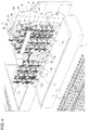
- number 1 indicates, as a whole, a gripping and moving unit to move, without distinctions, both one-piece and layered glass sheets 2 or spacers 3 designed to be interposed between two consecutive glass sheets 2 or between two overlapping stacks of glass sheets 2.
- the unit 1 comprises a wheel conveyor 4 - which is known and, therefore, not described in detail herein - defining a support and feeding plane P to support and feed both the glass sheets 2 and the spacers 3 in a direction 5, as well as a plurality of stands 6, three of them in the case shown herein, which are also known and are arranged on opposite sides of the conveyor 4 to support, without distinctions, stacks of glass sheets 2 interleaved with the spacers 3, common stack of glass sheets 2 separated from one another by spacers 3 or even stacks of spacers 3.
- the unit 1 further comprises an overhead-crane gripping and moving device 10 for the glass sheets 2 and the spacers 3.
- the device 10 comprises a suction gripping apparatus 11, which is known and, in turn, comprises a motor-driven bearing frame 12 coupled to a plurality of suction assemblies 13 to grip both the glass sheets 2 and the spacers 3.
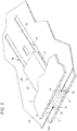
- each spacer 3 comprises a metal plate 15.
- the plate conveniently has a rectangular shape and a thickness ranging from 1 to 5 millimetres.
- the plate preferably has a thickness of approximately 2 millimetres.
- the term "approximately” indicates a 10% thickness variation.
- each plate conveniently has outer dimensions that are equal to or round down the outer dimensions of the glass sheets 2. According to a variant which is not shown herein, each metal plate 15 has outer dimensions that are smaller than the ones of the glass sheets 2.
- Each metal plate 15 has a plurality of circular through openings 18 distributed along the plate 15.
- the distribution of the openings 18 on the plate 15 is determined in such a way that the plate 15 has a stable shape and so as to create an alternation between the openings 18 and the solid portions 19 of the plate 15, so that, during the pick-up step, at least part of the solid portions 19 can be coupled to a relative suction assembly 13, regardless of the distribution of the suction assemblies on a suction gripping assembly.
- each spacer 3 has a central portion 20 and two side portions 21; the central portion 20 has a greater density of through openings 18 compared to the one of the side portions 21. The different density of openings allows users to move and handle sheets with different geometries and different dimensions. In the spacers 3, the through openings 18 conveniently have the same diameter.
- each metal plate 15 further has a plurality of through openings 23, which conveniently - though not necessarily - have a rectangular shape.
- each metal plate 15 the openings 23 are distributed along a ring following the peripheral edge of the plate 15 and along intermediate rows, in the case described herein three intermediate rows, parallel to one another and to a larger side of the metal plate 15 ( figures 1 and 4 ).
- Each one of the openings 23 houses an intermediate portion 25 of a respective spacer block 26 ( figures 1 , 2 and 4 ), which is made of an elastomer material or of glass fibre or of other equivalent materials designed to cooperate with the glass sheets 2 without scratching or scraping them.
- Each spacer block 26 comprises a pair of abutment side portions 27 opposite one another, each of them projecting from a relative side surface 15A of the metal plate 15 and designed to be arranged, in use, so as to rest against a relative glass sheet 2.
- each block 26 is coupled to the metal plate 15 by means of a releasable coupling device, indicated with 28 ( figure 2 ).
- Each device 28 comprises a slide and drive assembly 29 comprising, in turn, a pair of appendixes 31, which are manufactured as one single piece together with the plate 15 and project towards one another inside the relative rectangular opening 23, and two counteracting grooves 32 obtained on the sides of the relative block 26.
- the appendixes 31 each engage a relative groove 32 in a sliding manner and the relative block 26 is axially stopped by an elastic appendix 33, which is also obtained as one single piece together with the plate 15, projects inside the relative opening 23 and forces the relative block 26 against the bottom of the relative opening 23.
- the devices 28 allow the blocks 26 to be quickly disassembled and replaced, if necessary, for example depending on the distribution of the gripping organs, with blocks with different shapes or dimensions or materials making up the blocks themselves.
- blocks with a different thickness are used to change the space between two consecutive glass sheets 2, which, for example, is required by the different stabilization treatments to which the glass sheets 2 can be subjected, especially the layered ones, after having been stacked in positions spaced apart by the spacers 3.
- the blocks 26 are firmly fixed to the metal plate 15 by means of rivets or screws or other equivalent connection means. Alternatively, furthermore, the blocks 26 are glued to the plate 15. In these last cases, the blocks 26 are common parallelepiped-shaped blocks without the grooves 32 and the metal plate 15 does not have all or part of the openings 23.
- the special manufacturing features of the spacers and, in particular, the fact that they comprise a metal plate with a constant thickness, which is designed to be handled by means of the suction head used to move the glass sheets allow manufacturers to significantly simplify known plants, reducing the dimensions and the manufacturing as well as functional costs thereof, since the apparatuses and the actuators dedicated to the sole gripping and moving of the spacers are eliminated.
- the suction gripping head which is always present in sheet handling plants, is shared and still used in the same manner, regardless of whether it transfers glass sheets or spacers.
- the openings 18 allow air to freely flow through the compartments present between two consecutive glass sheets 2, thus allowing said glass sheets 2 to be subjected to any stabilization treatment, including autoclave treatments.
- the solid portions 19 present between the different openings ensure a stable shape under stress conditions and, in use, allow the suction cups to be attached in distributed points so that the spacers 3 have a stable shape even during the handling.
- the spacers 3 described herein can be moved along the same trajectories followed for the glass sheets 2 and after having distributed the suction gripping organs of the gripping head based on the type of sheet.
- the spacers 3 described herein can be stacked just like common glass sheets even in the gripping stations or in any point of the glass sheet feeding path and/or be moved by the glass sheet transferring/handling plants, since they can be compared to common glass sheets.
- the quick coupling and removal of the blocks 26 to and from the metal plate 15 allows for an easy reconditioning of the spacers 3 in case they are worn out or, if necessary, a quick readjustment thereof in order to space apart different glass sheets or carry out a different treatment of the glass sheets.
- the spacers 3 described above can be subjected to changes and variations.
- the openings 18 and 23 can be available in a different number and/or they can be distributed differently from what described and shown in the accompanying figures.
- the blocks 26 can be coupled to the metal plate 15 in a different way from the one described herein and/or be made of a different material from the one indicated herein.
- the metal plate 15 can have outer dimensions that are much smaller than the ones of the glass sheets 2 and can be provided with stiffening ribs or bulges having a height that is smaller than the one of the blocks 26 so as not to interfere with the glass sheets 2.
Landscapes
- Engineering & Computer Science (AREA)
- Mechanical Engineering (AREA)
- Robotics (AREA)
- Sheets, Magazines, And Separation Thereof (AREA)
- Load-Engaging Elements For Cranes (AREA)
- Manipulator (AREA)
Claims (11)
- Handhabungseinheit (1) für Glasscheiben (2) und ein Abstandshalter (3), der so ausgestaltet ist, dass er zwischen einer ersten und mindestens einer zweiten Glasscheibe (2) eingefügt ist; wobei die Einheit (1) eine Stützebene (P) für die Scheiben (2) oder den Abstandshalter (3), mindestens eine Glasscheibengreif- oder Glasscheibenlösestation (4), und mindestens eine Abstandshaltergreif- oder Abstandshalterlösestation (6) aufweist, die um die Stützebene (P) herum angeordnet sind; wobei der Abstandshalter entfernbar ist; wobei die Handhabungseinheit und der Abstandshalter dadurch gekennzeichnet sind, dass der Abstandshalter (3) eine Metallplatte (15) und eine Vielzahl von Abstandshalterblöcken (26) aufweist, die aus einem anderen Material als dem der Metallplatte (15) hergestellt sind und in einer freitragenden Weise von entgegengesetzten Seiten der Metallplatte (15) vorstehen, dass die Metallplatte (15) eine Vielzahl von Durchgangsöffnungen (23) und eine Vielzahl von festen Abschnitten (19) aufweist, die mit den Durchgangsöffnungen (23) verschachtelt sind, und dass die Einheit (1) ferner eine einzelne Bewegungs- und Greifsauganordnung (10, 13) aufweist, die dazu ausgebildet ist, sich unabhängig an die Glasscheiben (2) und die festen Abschnitte (19) des Abstandshalters (3) zu koppeln, um die Scheiben (2) und den Abstandshalter (3) von der Stützebene (P) weg oder zu ihr hin zu bewegen.
- Handhabungseinheit und Abstandshalter nach Anspruch 1, dadurch gekennzeichnet, dass zumindest ein Teil der Abstandshalterblöcke (26) zumindest teilweise in eine der Durchgangsöffnungen (23) eingreift.
- Handhabungseinheit und Abstandshalter nach Anspruch 1 oder 2, dadurch gekennzeichnet, dass zumindest ein Teil der Abstandshalterblöcke (26) mit der Platte durch entsprechende lösbare Verbindungsmittel (28) gekoppelt ist.
- Handhabungseinheit und Abstandshalter nach Anspruch 3, dadurch gekennzeichnet, dass die lösbaren Verbindungsmittel (28) Schnappverbindungsmittel sind.
- Handhabungseinheit und Abstandshalter nach Anspruch 4, dadurch gekennzeichnet, dass die Verbindungsmittel (28) für zumindest einen Teil der Abstandshalterblöcke (26) entsprechende Gleit- und Antriebsanordnungen (29) und entsprechende elastische Rückhaltefortsätze (33) aufweisen; wobei jeder der Rückhaltefortsätze (33) durch einen relativen Abschnitt der Platte definiert wird und an dem entsprechenden Abstandsblock (26) anliegend zusammenwirkt.
- Handhabungseinheit und Abstandshalter nach Anspruch 5, dadurch gekennzeichnet, dass jede Gleit- und Antriebsanordnung (29) ein Paar von entgegenwirkenden Nuten (32) aufweist, die auf den Seiten des Abstandshalters erhalten werden und von entsprechenden Abschnitten der Platte gleitend in Eingriff genommen werden.
- Handhabungseinheit und Abstandshalter nach einem der vorstehenden Ansprüche, dadurch gekennzeichnet, dass die Abstandshalterblöcke (26) durch Blöcke unabhängig voneinander gebildet werden.
- Handhabungseinheit und Abstandshalter nach einem der vorstehenden Ansprüche, dadurch gekennzeichnet, dass die Abstandshalterblöcke (26) aus einem elastomeren Material, Papier oder Polyurethan oder Verbundmaterial hergestellt sind.
- Handhabungseinheit und Abstandshalter nach einem der vorstehenden Ansprüche, dadurch gekennzeichnet, dass die Metallplatte (15) einstückig ausgebildet ist.
- Handhabungseinheit und Abstandshalter nach einem der vorstehenden Ansprüche, dadurch gekennzeichnet, dass die Metallplatte durch ein Metallblech mit einer konstanten Dicke definiert wird.
- Handhabungsverfahren für einen entfernbaren Abstandshalter, der so ausgestaltet ist, dass er zwischen mindestens einer ersten und mindestens einer zweiten Glasscheibe eingefügt ist; wobei das Verfahren die Schritte des Greifens des Abstandshalters mittels eines Greifkopfs und des Bewegens des Abstandshalters weg von oder zu einer der Scheiben umfasst, dadurch gekennzeichnet, dass das Greifen und Bewegen des Abstandshalters von einer Handhabungseinheit und einem Abstandshalter nach Anspruch 1 durchgeführt werden, und dass die einzelne Bewegungs- und Greifsauganordnung (10, 13) dieselbe einzelne Bewegungs- und Greifsauganordnung (10, 13) ist, die zur Bewegung der Glasscheibe (2) verwendet wird.
Applications Claiming Priority (1)
| Application Number | Priority Date | Filing Date | Title |
|---|---|---|---|
| IT102017000110679A IT201700110679A1 (it) | 2017-10-03 | 2017-10-03 | Distanziale rimuovibile per distanziare lastre di vetro e metodo di manipolazione dello stesso distanziale |
Publications (2)
| Publication Number | Publication Date |
|---|---|
| EP3466833A1 EP3466833A1 (de) | 2019-04-10 |
| EP3466833B1 true EP3466833B1 (de) | 2021-12-01 |
Family
ID=61187654
Family Applications (1)
| Application Number | Title | Priority Date | Filing Date |
|---|---|---|---|
| EP18198512.8A Active EP3466833B1 (de) | 2017-10-03 | 2018-10-03 | Handhabungseinheit für glasscheiben und abstandhalter, verfahren zur handhabung |
Country Status (2)
| Country | Link |
|---|---|
| EP (1) | EP3466833B1 (de) |
| IT (1) | IT201700110679A1 (de) |
Families Citing this family (1)
| Publication number | Priority date | Publication date | Assignee | Title |
|---|---|---|---|---|
| CN114524269B (zh) * | 2022-02-23 | 2024-01-05 | 厦门莱蔓新材料科技有限公司 | 一种基于视觉监测智能抓取的板材输送设备以及方法 |
Citations (1)
| Publication number | Priority date | Publication date | Assignee | Title |
|---|---|---|---|---|
| JP2016013874A (ja) * | 2015-10-15 | 2016-01-28 | 大日本印刷株式会社 | 基板用トレイ |
Family Cites Families (4)
| Publication number | Priority date | Publication date | Assignee | Title |
|---|---|---|---|---|
| JP2010208641A (ja) * | 2009-03-06 | 2010-09-24 | Sharp Corp | パネル梱包方法、パネル開梱方法、パネル梱包装置、パネル開梱装置およびパネル梱包用合紙 |
| WO2013042565A1 (ja) * | 2011-09-20 | 2013-03-28 | 日本電気硝子株式会社 | 液晶素子及び液晶素子用セル |
| CN103171893B (zh) * | 2013-03-06 | 2015-12-23 | 昆山龙腾光电有限公司 | 显示面板及垫片的取放和分离装置及取放和分离方法 |
| SE1500219A1 (sv) * | 2015-05-07 | 2016-11-08 | Lars Eriksson Dev Ab | Anordning vid ett distanselement mellan skivenheter |
-
2017
- 2017-10-03 IT IT102017000110679A patent/IT201700110679A1/it unknown
-
2018
- 2018-10-03 EP EP18198512.8A patent/EP3466833B1/de active Active
Patent Citations (1)
| Publication number | Priority date | Publication date | Assignee | Title |
|---|---|---|---|---|
| JP2016013874A (ja) * | 2015-10-15 | 2016-01-28 | 大日本印刷株式会社 | 基板用トレイ |
Also Published As
| Publication number | Publication date |
|---|---|
| EP3466833A1 (de) | 2019-04-10 |
| IT201700110679A1 (it) | 2019-04-03 |
Similar Documents
| Publication | Publication Date | Title |
|---|---|---|
| EP3165483B1 (de) | Vorrichtung zur sortierung von gegenständen | |
| DK162585B (da) | Udtageindretning til varmformede, hule, med rand forsynede genstande af formstof | |
| US6623236B1 (en) | Vacuum apparatus and method for denesting objects | |
| US10138078B2 (en) | De-stacking device for de-stacking layers of transport pallets with or without intermediary layers | |
| EP2432696A1 (de) | System, greifkopf und verfahren zum verschieben von produkten | |
| CA2863437C (en) | Method and device for separating and stacking food slices | |
| CA2549035C (en) | Method and device for handling rod-shaped objects | |
| EP3466833A1 (de) | Entfernbarer abstandshalter zur beabstandung von glasscheiben und handhabungsverfahren dieses abstandshalters | |
| US10286596B2 (en) | Apparatus for thermoforming plastic containers | |
| EP2734355A1 (de) | Ladevorrichtung und verfahren für thermoformung von folien | |
| CN107206613B (zh) | 用于分割板状工件的板材分割设备及其运行方法 | |
| CA2992132A1 (en) | Method for unstacking veneer sheets | |
| EP3307657B1 (de) | Vorrichtung zur sortierung von gegenständen | |
| JP2011172527A (ja) | 寿司の製造システムおよび寿司の製造方法 | |
| CN114084691B (zh) | 一种异形钣金件的自动定位抓取装置 | |
| KR20180135692A (ko) | U 볼트 성형 장치 | |
| EP2692669B1 (de) | Vorrichtung zum stapeln von fliesen | |
| US10858207B2 (en) | Apparatus for unstacking packaging units | |
| EP3241664B1 (de) | Vorrichtung zur warmformung eines kunststoffbehälters | |
| US10625462B2 (en) | Apparatus for thermoforming plastic containers | |
| EP3723936B1 (de) | Verfahren und system zur handhabung von strahlgeschnittenen teilen durch bereitstellung eines greifers | |
| EP3621789B1 (de) | Vorrichtung zum transportieren von flachen bögen und nachfolgende formung von kartonschachteln | |
| NL2037431B1 (en) | Method and system for processing a group of egg trays | |
| EP3849389B1 (de) | Vorrichtung zum aufschlagen von eiern | |
| CA2933088A1 (en) | Hot stamp cell |
Legal Events
| Date | Code | Title | Description |
|---|---|---|---|
| PUAI | Public reference made under article 153(3) epc to a published international application that has entered the european phase |
Free format text: ORIGINAL CODE: 0009012 |
|
| STAA | Information on the status of an ep patent application or granted ep patent |
Free format text: STATUS: THE APPLICATION HAS BEEN PUBLISHED |
|
| AK | Designated contracting states |
Kind code of ref document: A1 Designated state(s): AL AT BE BG CH CY CZ DE DK EE ES FI FR GB GR HR HU IE IS IT LI LT LU LV MC MK MT NL NO PL PT RO RS SE SI SK SM TR |
|
| AX | Request for extension of the european patent |
Extension state: BA ME |
|
| STAA | Information on the status of an ep patent application or granted ep patent |
Free format text: STATUS: REQUEST FOR EXAMINATION WAS MADE |
|
| 17P | Request for examination filed |
Effective date: 20191009 |
|
| STAA | Information on the status of an ep patent application or granted ep patent |
Free format text: STATUS: EXAMINATION IS IN PROGRESS |
|
| 17Q | First examination report despatched |
Effective date: 20200528 |
|
| GRAP | Despatch of communication of intention to grant a patent |
Free format text: ORIGINAL CODE: EPIDOSNIGR1 |
|
| STAA | Information on the status of an ep patent application or granted ep patent |
Free format text: STATUS: GRANT OF PATENT IS INTENDED |
|
| RIC1 | Information provided on ipc code assigned before grant |
Ipc: B65D 57/00 20060101AFI20210511BHEP Ipc: B65B 23/20 20060101ALI20210511BHEP Ipc: B65D 85/48 20060101ALN20210511BHEP Ipc: B65G 49/06 20060101ALN20210511BHEP Ipc: B25J 9/02 20060101ALN20210511BHEP Ipc: B25J 15/00 20060101ALN20210511BHEP Ipc: B25J 15/06 20060101ALN20210511BHEP |
|
| INTG | Intention to grant announced |
Effective date: 20210609 |
|
| GRAS | Grant fee paid |
Free format text: ORIGINAL CODE: EPIDOSNIGR3 |
|
| GRAA | (expected) grant |
Free format text: ORIGINAL CODE: 0009210 |
|
| STAA | Information on the status of an ep patent application or granted ep patent |
Free format text: STATUS: THE PATENT HAS BEEN GRANTED |
|
| AK | Designated contracting states |
Kind code of ref document: B1 Designated state(s): AL AT BE BG CH CY CZ DE DK EE ES FI FR GB GR HR HU IE IS IT LI LT LU LV MC MK MT NL NO PL PT RO RS SE SI SK SM TR |
|
| REG | Reference to a national code |
Ref country code: GB Ref legal event code: FG4D |
|
| REG | Reference to a national code |
Ref country code: AT Ref legal event code: REF Ref document number: 1451567 Country of ref document: AT Kind code of ref document: T Effective date: 20211215 Ref country code: CH Ref legal event code: EP |
|
| REG | Reference to a national code |
Ref country code: IE Ref legal event code: FG4D |
|
| REG | Reference to a national code |
Ref country code: DE Ref legal event code: R096 Ref document number: 602018027400 Country of ref document: DE |
|
| REG | Reference to a national code |
Ref country code: LT Ref legal event code: MG9D |
|
| REG | Reference to a national code |
Ref country code: NL Ref legal event code: MP Effective date: 20211201 |
|
| REG | Reference to a national code |
Ref country code: AT Ref legal event code: MK05 Ref document number: 1451567 Country of ref document: AT Kind code of ref document: T Effective date: 20211201 |
|
| PG25 | Lapsed in a contracting state [announced via postgrant information from national office to epo] |
Ref country code: RS Free format text: LAPSE BECAUSE OF FAILURE TO SUBMIT A TRANSLATION OF THE DESCRIPTION OR TO PAY THE FEE WITHIN THE PRESCRIBED TIME-LIMIT Effective date: 20211201 Ref country code: LT Free format text: LAPSE BECAUSE OF FAILURE TO SUBMIT A TRANSLATION OF THE DESCRIPTION OR TO PAY THE FEE WITHIN THE PRESCRIBED TIME-LIMIT Effective date: 20211201 Ref country code: FI Free format text: LAPSE BECAUSE OF FAILURE TO SUBMIT A TRANSLATION OF THE DESCRIPTION OR TO PAY THE FEE WITHIN THE PRESCRIBED TIME-LIMIT Effective date: 20211201 Ref country code: BG Free format text: LAPSE BECAUSE OF FAILURE TO SUBMIT A TRANSLATION OF THE DESCRIPTION OR TO PAY THE FEE WITHIN THE PRESCRIBED TIME-LIMIT Effective date: 20220301 Ref country code: AT Free format text: LAPSE BECAUSE OF FAILURE TO SUBMIT A TRANSLATION OF THE DESCRIPTION OR TO PAY THE FEE WITHIN THE PRESCRIBED TIME-LIMIT Effective date: 20211201 |
|
| PG25 | Lapsed in a contracting state [announced via postgrant information from national office to epo] |
Ref country code: SE Free format text: LAPSE BECAUSE OF FAILURE TO SUBMIT A TRANSLATION OF THE DESCRIPTION OR TO PAY THE FEE WITHIN THE PRESCRIBED TIME-LIMIT Effective date: 20211201 Ref country code: PL Free format text: LAPSE BECAUSE OF FAILURE TO SUBMIT A TRANSLATION OF THE DESCRIPTION OR TO PAY THE FEE WITHIN THE PRESCRIBED TIME-LIMIT Effective date: 20211201 Ref country code: NO Free format text: LAPSE BECAUSE OF FAILURE TO SUBMIT A TRANSLATION OF THE DESCRIPTION OR TO PAY THE FEE WITHIN THE PRESCRIBED TIME-LIMIT Effective date: 20220301 Ref country code: LV Free format text: LAPSE BECAUSE OF FAILURE TO SUBMIT A TRANSLATION OF THE DESCRIPTION OR TO PAY THE FEE WITHIN THE PRESCRIBED TIME-LIMIT Effective date: 20211201 Ref country code: HR Free format text: LAPSE BECAUSE OF FAILURE TO SUBMIT A TRANSLATION OF THE DESCRIPTION OR TO PAY THE FEE WITHIN THE PRESCRIBED TIME-LIMIT Effective date: 20211201 Ref country code: GR Free format text: LAPSE BECAUSE OF FAILURE TO SUBMIT A TRANSLATION OF THE DESCRIPTION OR TO PAY THE FEE WITHIN THE PRESCRIBED TIME-LIMIT Effective date: 20220302 Ref country code: ES Free format text: LAPSE BECAUSE OF FAILURE TO SUBMIT A TRANSLATION OF THE DESCRIPTION OR TO PAY THE FEE WITHIN THE PRESCRIBED TIME-LIMIT Effective date: 20211201 |
|
| PG25 | Lapsed in a contracting state [announced via postgrant information from national office to epo] |
Ref country code: NL Free format text: LAPSE BECAUSE OF FAILURE TO SUBMIT A TRANSLATION OF THE DESCRIPTION OR TO PAY THE FEE WITHIN THE PRESCRIBED TIME-LIMIT Effective date: 20211201 |
|
| PG25 | Lapsed in a contracting state [announced via postgrant information from national office to epo] |
Ref country code: SM Free format text: LAPSE BECAUSE OF FAILURE TO SUBMIT A TRANSLATION OF THE DESCRIPTION OR TO PAY THE FEE WITHIN THE PRESCRIBED TIME-LIMIT Effective date: 20211201 Ref country code: SK Free format text: LAPSE BECAUSE OF FAILURE TO SUBMIT A TRANSLATION OF THE DESCRIPTION OR TO PAY THE FEE WITHIN THE PRESCRIBED TIME-LIMIT Effective date: 20211201 Ref country code: RO Free format text: LAPSE BECAUSE OF FAILURE TO SUBMIT A TRANSLATION OF THE DESCRIPTION OR TO PAY THE FEE WITHIN THE PRESCRIBED TIME-LIMIT Effective date: 20211201 Ref country code: PT Free format text: LAPSE BECAUSE OF FAILURE TO SUBMIT A TRANSLATION OF THE DESCRIPTION OR TO PAY THE FEE WITHIN THE PRESCRIBED TIME-LIMIT Effective date: 20220401 Ref country code: EE Free format text: LAPSE BECAUSE OF FAILURE TO SUBMIT A TRANSLATION OF THE DESCRIPTION OR TO PAY THE FEE WITHIN THE PRESCRIBED TIME-LIMIT Effective date: 20211201 Ref country code: CZ Free format text: LAPSE BECAUSE OF FAILURE TO SUBMIT A TRANSLATION OF THE DESCRIPTION OR TO PAY THE FEE WITHIN THE PRESCRIBED TIME-LIMIT Effective date: 20211201 |
|
| REG | Reference to a national code |
Ref country code: DE Ref legal event code: R097 Ref document number: 602018027400 Country of ref document: DE |
|
| PG25 | Lapsed in a contracting state [announced via postgrant information from national office to epo] |
Ref country code: IS Free format text: LAPSE BECAUSE OF FAILURE TO SUBMIT A TRANSLATION OF THE DESCRIPTION OR TO PAY THE FEE WITHIN THE PRESCRIBED TIME-LIMIT Effective date: 20220401 |
|
| PLBE | No opposition filed within time limit |
Free format text: ORIGINAL CODE: 0009261 |
|
| STAA | Information on the status of an ep patent application or granted ep patent |
Free format text: STATUS: NO OPPOSITION FILED WITHIN TIME LIMIT |
|
| PG25 | Lapsed in a contracting state [announced via postgrant information from national office to epo] |
Ref country code: DK Free format text: LAPSE BECAUSE OF FAILURE TO SUBMIT A TRANSLATION OF THE DESCRIPTION OR TO PAY THE FEE WITHIN THE PRESCRIBED TIME-LIMIT Effective date: 20211201 Ref country code: AL Free format text: LAPSE BECAUSE OF FAILURE TO SUBMIT A TRANSLATION OF THE DESCRIPTION OR TO PAY THE FEE WITHIN THE PRESCRIBED TIME-LIMIT Effective date: 20211201 |
|
| 26N | No opposition filed |
Effective date: 20220902 |
|
| PG25 | Lapsed in a contracting state [announced via postgrant information from national office to epo] |
Ref country code: SI Free format text: LAPSE BECAUSE OF FAILURE TO SUBMIT A TRANSLATION OF THE DESCRIPTION OR TO PAY THE FEE WITHIN THE PRESCRIBED TIME-LIMIT Effective date: 20211201 |
|
| PG25 | Lapsed in a contracting state [announced via postgrant information from national office to epo] |
Ref country code: MC Free format text: LAPSE BECAUSE OF FAILURE TO SUBMIT A TRANSLATION OF THE DESCRIPTION OR TO PAY THE FEE WITHIN THE PRESCRIBED TIME-LIMIT Effective date: 20211201 |
|
| REG | Reference to a national code |
Ref country code: CH Ref legal event code: PL |
|
| REG | Reference to a national code |
Ref country code: BE Ref legal event code: MM Effective date: 20221031 |
|
| GBPC | Gb: european patent ceased through non-payment of renewal fee |
Effective date: 20221003 |
|
| PG25 | Lapsed in a contracting state [announced via postgrant information from national office to epo] |
Ref country code: LU Free format text: LAPSE BECAUSE OF NON-PAYMENT OF DUE FEES Effective date: 20221003 |
|
| PG25 | Lapsed in a contracting state [announced via postgrant information from national office to epo] |
Ref country code: LI Free format text: LAPSE BECAUSE OF NON-PAYMENT OF DUE FEES Effective date: 20221031 Ref country code: FR Free format text: LAPSE BECAUSE OF NON-PAYMENT OF DUE FEES Effective date: 20221031 Ref country code: CH Free format text: LAPSE BECAUSE OF NON-PAYMENT OF DUE FEES Effective date: 20221031 |
|
| PG25 | Lapsed in a contracting state [announced via postgrant information from national office to epo] |
Ref country code: BE Free format text: LAPSE BECAUSE OF NON-PAYMENT OF DUE FEES Effective date: 20221031 |
|
| PG25 | Lapsed in a contracting state [announced via postgrant information from national office to epo] |
Ref country code: IE Free format text: LAPSE BECAUSE OF NON-PAYMENT OF DUE FEES Effective date: 20221003 Ref country code: GB Free format text: LAPSE BECAUSE OF NON-PAYMENT OF DUE FEES Effective date: 20221003 |
|
| PG25 | Lapsed in a contracting state [announced via postgrant information from national office to epo] |
Ref country code: HU Free format text: LAPSE BECAUSE OF FAILURE TO SUBMIT A TRANSLATION OF THE DESCRIPTION OR TO PAY THE FEE WITHIN THE PRESCRIBED TIME-LIMIT; INVALID AB INITIO Effective date: 20181003 |
|
| PG25 | Lapsed in a contracting state [announced via postgrant information from national office to epo] |
Ref country code: CY Free format text: LAPSE BECAUSE OF FAILURE TO SUBMIT A TRANSLATION OF THE DESCRIPTION OR TO PAY THE FEE WITHIN THE PRESCRIBED TIME-LIMIT Effective date: 20211201 |
|
| PG25 | Lapsed in a contracting state [announced via postgrant information from national office to epo] |
Ref country code: MK Free format text: LAPSE BECAUSE OF FAILURE TO SUBMIT A TRANSLATION OF THE DESCRIPTION OR TO PAY THE FEE WITHIN THE PRESCRIBED TIME-LIMIT Effective date: 20211201 |
|
| PG25 | Lapsed in a contracting state [announced via postgrant information from national office to epo] |
Ref country code: TR Free format text: LAPSE BECAUSE OF FAILURE TO SUBMIT A TRANSLATION OF THE DESCRIPTION OR TO PAY THE FEE WITHIN THE PRESCRIBED TIME-LIMIT Effective date: 20211201 |
|
| PG25 | Lapsed in a contracting state [announced via postgrant information from national office to epo] |
Ref country code: MT Free format text: LAPSE BECAUSE OF FAILURE TO SUBMIT A TRANSLATION OF THE DESCRIPTION OR TO PAY THE FEE WITHIN THE PRESCRIBED TIME-LIMIT Effective date: 20211201 |
|
| PGFP | Annual fee paid to national office [announced via postgrant information from national office to epo] |
Ref country code: IT Payment date: 20250923 Year of fee payment: 8 |
|
| PGFP | Annual fee paid to national office [announced via postgrant information from national office to epo] |
Ref country code: DE Payment date: 20250923 Year of fee payment: 8 |