EP3466622B1 - Brotschneidemaschine - Google Patents
Brotschneidemaschine Download PDFInfo
- Publication number
- EP3466622B1 EP3466622B1 EP18186586.6A EP18186586A EP3466622B1 EP 3466622 B1 EP3466622 B1 EP 3466622B1 EP 18186586 A EP18186586 A EP 18186586A EP 3466622 B1 EP3466622 B1 EP 3466622B1
- Authority
- EP
- European Patent Office
- Prior art keywords
- pushing
- bread
- cutting
- edge
- cutting machine
- Prior art date
- Legal status (The legal status is an assumption and is not a legal conclusion. Google has not performed a legal analysis and makes no representation as to the accuracy of the status listed.)
- Active
Links
Images


Classifications
-
- B—PERFORMING OPERATIONS; TRANSPORTING
- B26—HAND CUTTING TOOLS; CUTTING; SEVERING
- B26D—CUTTING; DETAILS COMMON TO MACHINES FOR PERFORATING, PUNCHING, CUTTING-OUT, STAMPING-OUT OR SEVERING
- B26D7/00—Details of apparatus for cutting, cutting-out, stamping-out, punching, perforating, or severing by means other than cutting
- B26D7/27—Means for performing other operations combined with cutting
- B26D7/32—Means for performing other operations combined with cutting for conveying or stacking cut product
- B26D7/325—Means for performing other operations combined with cutting for conveying or stacking cut product stacking the cut product individually separated by separator elements
-
- B—PERFORMING OPERATIONS; TRANSPORTING
- B26—HAND CUTTING TOOLS; CUTTING; SEVERING
- B26D—CUTTING; DETAILS COMMON TO MACHINES FOR PERFORATING, PUNCHING, CUTTING-OUT, STAMPING-OUT OR SEVERING
- B26D1/00—Cutting through work characterised by the nature or movement of the cutting member or particular materials not otherwise provided for; Apparatus or machines therefor; Cutting members therefor
-
- B—PERFORMING OPERATIONS; TRANSPORTING
- B26—HAND CUTTING TOOLS; CUTTING; SEVERING
- B26D—CUTTING; DETAILS COMMON TO MACHINES FOR PERFORATING, PUNCHING, CUTTING-OUT, STAMPING-OUT OR SEVERING
- B26D7/00—Details of apparatus for cutting, cutting-out, stamping-out, punching, perforating, or severing by means other than cutting
- B26D7/06—Arrangements for feeding or delivering work of other than sheet, web, or filamentary form
- B26D7/0616—Arrangements for feeding or delivering work of other than sheet, web, or filamentary form by carriages, e.g. for slicing machines
-
- B—PERFORMING OPERATIONS; TRANSPORTING
- B26—HAND CUTTING TOOLS; CUTTING; SEVERING
- B26D—CUTTING; DETAILS COMMON TO MACHINES FOR PERFORATING, PUNCHING, CUTTING-OUT, STAMPING-OUT OR SEVERING
- B26D7/00—Details of apparatus for cutting, cutting-out, stamping-out, punching, perforating, or severing by means other than cutting
- B26D7/06—Arrangements for feeding or delivering work of other than sheet, web, or filamentary form
- B26D7/0683—Arrangements for feeding or delivering work of other than sheet, web, or filamentary form specially adapted for elongated articles
-
- B—PERFORMING OPERATIONS; TRANSPORTING
- B65—CONVEYING; PACKING; STORING; HANDLING THIN OR FILAMENTARY MATERIAL
- B65B—MACHINES, APPARATUS OR DEVICES FOR, OR METHODS OF, PACKAGING ARTICLES OR MATERIALS; UNPACKING
- B65B25/00—Packaging other articles presenting special problems
- B65B25/16—Packaging bread or like bakery products, e.g. unsliced loaves
- B65B25/18—Wrapping sliced bread
-
- A—HUMAN NECESSITIES
- A47—FURNITURE; DOMESTIC ARTICLES OR APPLIANCES; COFFEE MILLS; SPICE MILLS; SUCTION CLEANERS IN GENERAL
- A47J—KITCHEN EQUIPMENT; COFFEE MILLS; SPICE MILLS; APPARATUS FOR MAKING BEVERAGES
- A47J47/00—Kitchen containers, stands or the like, not provided for in other groups of this subclass; Cutting-boards, e.g. for bread
-
- B—PERFORMING OPERATIONS; TRANSPORTING
- B26—HAND CUTTING TOOLS; CUTTING; SEVERING
- B26D—CUTTING; DETAILS COMMON TO MACHINES FOR PERFORATING, PUNCHING, CUTTING-OUT, STAMPING-OUT OR SEVERING
- B26D1/00—Cutting through work characterised by the nature or movement of the cutting member or particular materials not otherwise provided for; Apparatus or machines therefor; Cutting members therefor
- B26D1/01—Cutting through work characterised by the nature or movement of the cutting member or particular materials not otherwise provided for; Apparatus or machines therefor; Cutting members therefor involving a cutting member which does not travel with the work
- B26D1/04—Cutting through work characterised by the nature or movement of the cutting member or particular materials not otherwise provided for; Apparatus or machines therefor; Cutting members therefor involving a cutting member which does not travel with the work having a linearly-movable cutting member
- B26D1/06—Cutting through work characterised by the nature or movement of the cutting member or particular materials not otherwise provided for; Apparatus or machines therefor; Cutting members therefor involving a cutting member which does not travel with the work having a linearly-movable cutting member wherein the cutting member reciprocates
- B26D1/10—Cutting through work characterised by the nature or movement of the cutting member or particular materials not otherwise provided for; Apparatus or machines therefor; Cutting members therefor involving a cutting member which does not travel with the work having a linearly-movable cutting member wherein the cutting member reciprocates in, or substantially in, a direction parallel to the cutting edge
- B26D1/11—Cutting through work characterised by the nature or movement of the cutting member or particular materials not otherwise provided for; Apparatus or machines therefor; Cutting members therefor involving a cutting member which does not travel with the work having a linearly-movable cutting member wherein the cutting member reciprocates in, or substantially in, a direction parallel to the cutting edge with a plurality of cutting members
-
- B—PERFORMING OPERATIONS; TRANSPORTING
- B26—HAND CUTTING TOOLS; CUTTING; SEVERING
- B26D—CUTTING; DETAILS COMMON TO MACHINES FOR PERFORATING, PUNCHING, CUTTING-OUT, STAMPING-OUT OR SEVERING
- B26D1/00—Cutting through work characterised by the nature or movement of the cutting member or particular materials not otherwise provided for; Apparatus or machines therefor; Cutting members therefor
- B26D1/01—Cutting through work characterised by the nature or movement of the cutting member or particular materials not otherwise provided for; Apparatus or machines therefor; Cutting members therefor involving a cutting member which does not travel with the work
- B26D1/547—Cutting through work characterised by the nature or movement of the cutting member or particular materials not otherwise provided for; Apparatus or machines therefor; Cutting members therefor involving a cutting member which does not travel with the work having a wire-like cutting member
- B26D1/553—Cutting through work characterised by the nature or movement of the cutting member or particular materials not otherwise provided for; Apparatus or machines therefor; Cutting members therefor involving a cutting member which does not travel with the work having a wire-like cutting member with a plurality of wire-like cutting members
-
- B—PERFORMING OPERATIONS; TRANSPORTING
- B26—HAND CUTTING TOOLS; CUTTING; SEVERING
- B26D—CUTTING; DETAILS COMMON TO MACHINES FOR PERFORATING, PUNCHING, CUTTING-OUT, STAMPING-OUT OR SEVERING
- B26D7/00—Details of apparatus for cutting, cutting-out, stamping-out, punching, perforating, or severing by means other than cutting
- B26D7/27—Means for performing other operations combined with cutting
- B26D7/32—Means for performing other operations combined with cutting for conveying or stacking cut product
- B26D2007/327—Means for performing other operations combined with cutting for conveying or stacking cut product the cut products being slices of bread
-
- B—PERFORMING OPERATIONS; TRANSPORTING
- B26—HAND CUTTING TOOLS; CUTTING; SEVERING
- B26D—CUTTING; DETAILS COMMON TO MACHINES FOR PERFORATING, PUNCHING, CUTTING-OUT, STAMPING-OUT OR SEVERING
- B26D2210/00—Machines or methods used for cutting special materials
- B26D2210/02—Machines or methods used for cutting special materials for cutting food products, e.g. food slicers
- B26D2210/06—Machines or methods used for cutting special materials for cutting food products, e.g. food slicers for bread, e.g. bread slicing machines for use in a retail store
Definitions
- the invention relates to a bread cutting machine for cutting bread, in particular a baguette, into slices.
- the invention further relates to a pushing device for use in such a bread cutting machine.
- a bread cutting machine as such is known.
- the known bread cutting machine comprises a receiving surface for receiving the bread to be cut, a cutting device placed at an edge of the receiving surface for cutting the bread into slices, and a pushing device configured for pushing the bread to be cut along the receiving surface towards and beyond the cutting device.
- a bread is inserted into the bread cutting machine.
- the bread is pushed towards the cutting device and is cut into slices by the cutting device when it reaches the cutting device.
- a bread slicer is known from EP 1 574 304 describing a device for slicing loafs or breads and other mainly elongated objects into slices, which device is constructed of two reciprocal oscillating supporting frames with in longitudinal direction fixed knives on one side, which in top view are applied in layers such as a wave- or V-shape to minimalize the compression of the bread with all its advantages and in which the mentioned knives are sharpened on one side in cross-section, in which in longitudinal direction the knives on the other side slide through a light guiding frame, in which the mentioned supporting frames move an eccentric mechanism up and down or forth and back and the bread is pushed through the knives by a pusher.
- a bread cutting machine can comprise a funnel-shaped outlet for loosening and transporting the bread slices from the bread cutting machine into the packaging bag.
- a disadvantage of the funnel-shaped outlet is that it becomes obstructed due to the bread slices passing there through simultaneously and, therefore, no bread slice exits the bread cutting machine.
- the invention provides a bread cutting machine for cutting bread, in particular a baguette, into slices, wherein the cutting device comprises:
- the longitudinal axis of the bread to be cut is at an acute angle to the first plane during cutting of the baguette. Due to the orientation of the baguette with respect to the first plane, the cutting blades of the array of cutting blades come into contact with the bread sequentially. The baguette slices, therefore, are loosened substantially sequentially from the baguette. After cutting the slice of baguette, the slice is caused to exit the bread cutting machine via an outlet, such as a funnel-shaped outlet. As a result, the slices leave the bread cutting machine substantially oneby-one, or in small groups of slices. It is thereby prevented that the outlet of the bread cutting machine, in particular the funnel-shaped outlet, becomes obstructed by the baguette slices.
- the slices are cut oblique with respect to the longitudinal axis of the baguette.
- an acute angle has to be understood as an angle larger than 0 degrees and smaller than 90 degrees.
- the first plane has to be understood as a plane extending through substantially all cutting blades of the array of cutting blades.
- the push surface is at an acute angle to the pushing direction and the first plane is substantially perpendicular to the pushing direction at least as viewed in in the direction perpendicular to the receiving plane.
- the receiving plane and the push surface are at least partially substantially perpendicular and/or at an acute angle to each other.
- the baguette can be forced at least partially towards the receiving surface and can be prevented from moving upwards for example during cutting thereof.
- the pushing device comprises a pushing member having a pushing body, wherein the pushing body defines the push surface.
- the pushing body is provided with a plurality of slits provided at the side of the pushing body that faces the cutting device, which slits are orientated substantially parallel to each other and/or to the pushing direction of the pushing device, wherein the plurality of slits defines a plurality of pushing fingers.
- the baguette has to be pushed beyond the cutting device in order to be cut into slices completely. Due to the slits in the pushing body, the pushing body is enabled to receive the cutting blades of the array of cutting blades. The pushing body, therefore, can keep pushing the baguette beyond the cutting device and thus until the baguette is cut into slices completely.
- the receiving surface has a third edge and a fourth edge opposite to the third edge, wherein each of the pushing fingers has a length in the pushing direction, wherein the length of the pushing fingers decreases in a direction from the third edge to the fourth edge, wherein a distance between the push surface and the first plane is smaller at the third edge than at the fourth edge.
- each of the pushing fingers has a contact part for contacting the bread to be cut, wherein the contact part of each of the pushing fingers is faced towards the cutting device, preferably wherein the contact parts of the pushing fingers together define the push surface.
- each of the contact parts is at an acute angle with respect to the receiving surface. Preferably the acute angle between the contact parts of the pushing fingers and the receiving plane increases in the direction from the third edge to the fourth edge. Due to the increasing acute angle between the contact parts of the pushing fingers and the receiving plane, the baguette can be kept in place/orientation during the entire process of cutting the baguette.
- the pushing device is provided with one or more retaining members, which one or more retaining members extend towards the cutting device.
- each of the one or more retaining members comprises a first part and a second part, wherein the first part is connected to the pushing device, and the second part is connected to the first part at the end of the first part facing the cutting device.
- the first part is orientated substantially parallel to the receiving surface, and the second part is placed at an obtuse angle with respect to the first part.
- a distance between each of the ends of the first parts facing the cutting device and the push surface is substantially equal for a majority of the one or more retaining members
- an obtuse angle has to be understood as an angle larger than 90 degrees and smaller than 180 degrees.
- the receiving surface has one or more guiding grooves extending between the first edge and the second edge and substantially parallel to each other.
- the one or more guiding grooves are configured for guiding the one or more retaining members, in particular the first parts thereof.
- the retaining members are kept in the guiding grooves which extend substantially parallel to the pushing direction. The retaining members, therefore, are prevented from moving in an undesired direction and the baguette can be retained in the desired position/orientation.
- the receiving plane and the first plane are substantially perpendicular or at an acute angle to each other.
- the baguette is at least partially enclosed by the array of cutting blades and the receiving surface during cutting of the baguette.
- the baguette is therewith prevented from moving due to the movement of the cutting blades which are cutting the baguette. This is advantageous, as the baguette can be kept in place.
- the receiving surface has a plurality of slits extending substantially parallel to each other and/or to the pushing direction, wherein each of the plurality of slits is configured for receiving a cutting blade of the array of cutting blades.
- the bread cutting machine comprises a driving mechanism operatively coupled with the cutting device and/or the pushing device, wherein the driving mechanism is configured for driving the cutting device and/or the pushing device.
- the invention provides a method for cutting bread slices from a bread, in particular a baguette, preferably by means of a bread cutting machine as described above, wherein the method comprises the steps of:
- the method further comprises the step of packing the bread slices into a packaging material, in particular a packaging bag.
- the angle between the longitudinal axis of the bread and the pushing direction is between 5 - 25 degrees, in particular between 7 - 15 degrees, more particular is about 10 or 11 degrees.
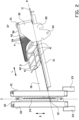
- a cutting machine 1 for cutting baguettes according to an embodiment of the invention is partially shown in figures 1 to 3 .
- the cutting machine 1 comprises a housing with an inlet (not shown) via which a baguette to be cut is inputted into the cutting machine 1.
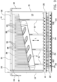
- the cutting machine 1 comprises a receiving surface 10 by which the inserted baguette 2 is received.
- the receiving surface 10 has a first edge 11 and a second edge 12 opposite to the first edge 11.
- a cutting device 20 for cutting the baguette into a plurality of slices is provided at the second edge 12 of the receiving surface 10.
- the cutting machine 1 further comprises a pushing device 30 for pushing the baguette 2 to be cut along the receiving surface 10 in a pushing direction L extending between the first and second edges 11, 12 of the receiving surface 10, towards and beyond the cutting device 20.
- the baguette slices for example, fall into a funnel (not shown) which leads the baguette slices to a packaging bag (not shown).
- the packaging bag can be removed from the cutting machine 1.
- the receiving surface 10 comprises a substantially flat receiving body 13 with a third edge 14 and a fourth edge 15 opposite to the third edge 14.
- a receiving plane R is defined by the flat receiving body 13.
- the receiving body 13 is provided with a number of grooves 16 which are extending from the second edge 12 towards the first edge 11 of the receiving body 13 and substantially parallel to the pushing direction L and to the third and fourth edges 14, 15.
- the receiving body 13 comprises a plurality of slits 17 also extending from the second edge 12 towards the first edge 11 of the receiving body 13 and substantially parallel to the pushing direction L.
- a guiding strip 18 is provided at the top surface of the receiving body 13, wherein the guiding strip 18 is attached near the third edge 14 of the receiving body 13 and extends between the first edge 11 and the second edge 12. The baguette 2 to be cut is placed against and guided by the guiding strip 18 during use.
- the cutting device 20 comprises among others a first frame part 21 and a second frame part 22, which first and second frame parts 21, 22 are placed parallel to each other.
- Each of the first and second frame parts 21, 22 comprises securing members 23 in order to secure the cutting device 20 to the cutting machine 1.
- the cutting device 20 further comprises an array of cutting blades 24 which are provided between the first frame part 21 and the second frame part 22 and which are moveable connected to the first and second frame parts 21, 22.
- the cutting blades 24 are moveable in a cutting direction S and the array of cutting blades 24 defines a first plane C.
- Each of the cutting blades 24 is made of a thin elongated metal plate or strip with a cutting edge facing the pushing device 30, wherein each thin elongated metal plate or strip is substantially perpendicular to the first plane C.
- the cutting blades 24 can be driven by means of a driving mechanism (not shown).
- the cutting device 20 is provided at the second edge 12 of the receiving surface 10, wherein the cutting blades 24 are received by the slits 17.
- the cutting device 20 and the operation thereof as such are known and no further clarification of the cutting device 20 is considered necessary.
- the pushing device 30 comprises a base part 31 which is placed above the top surface of the receiving surface 10. As shown in figure 3 the base part 31 extends over the complete width of the receiving surface 10.
- the base part 31 comprises a first coupling part 32 and a second coupling part 33, each provided with a coupling aperture 34.
- the pushing device 30, during use is coupled to a driving mechanism (not shown) by means of the first coupling part 32 and the second coupling part 33, which might be the same driving mechanism as used for the cutting device 20.
- the driving mechanism drives the base part 31 and thus the baguette 2 towards the cutting device 20 along the pushing direction L when activated.
- the base part 31 has a guide hole 35 which is configured for receiving the guiding strip 18 attached to the receiving surface 10.
- the pushing device 30 further comprises a pushing member 36 defining a push surface P.
- the pushing member 36 has a hollow pushing body 37 which is provided with a number of slits 38, thereby defining a number of pushing fingers 39.
- the slits 38 are configured for receiving the cutting blades 24 of the cutting device 20 when the pushing device 30 pushes the baguette 2 beyond the cutting device 20.
- Each of the pushing fingers 39 has a contact part 40 which is in contact with the baguette 2 during pushing thereof.
- each of the pushing fingers 39 has a length in the pushing direction L.
- the length of the pushing fingers 39 gradually decreases in a direction from the third edge 14 to the fourth edge 15.
- the push surface P defined by the pushing fingers 39 therefore, is at an acute angle with respect to the pushing direction L and at least as viewed in a direction substantially perpendicular to the receiving surface 10.
- the angle between the push surface P and the pushing direction L can be between 5 - 25 degrees, in particular between 7 - 15 degrees, more particular can be about 10 or 11 degrees.
- the contact part 40 of each of the pushing fingers 39 is at an acute angle with respect to the receiving plane R defined by the receiving surface 10.
- the acute angle between the front parts 40 of the pushing fingers 39 and the receiving plane R gradually increases in a direction from the third edge 14 to the fourth edge 15.
- the baguette 2 therefore, becomes partially placed between the receiving surface 10 and at least a part of the pushing fingers 39 at least when being pushed, as shown in figure 3 .
- the pushing device 3 further comprises retaining members 41 which are secured to the hollow pushing body 37 and are extending from the hollow pushing body 37 towards the cutting device 20.
- Each of the retaining members 41 comprises a first part 42, which is configured to be received by one of the grooves 16 in the receiving body 13 and to be moveable through the grooves 16.
- a second part 43 is attached to the first part 42.
- the second part 43 is placed at an obtuse angle with respect to the first part 42 and to the receiving plane 3.
- the retaining members 41 define a retaining space for retaining the baguette 2 to be cut.
- the baguette 2 is inserted into the cutting machine 1 via the inlet in the housing and is guided towards the receiving surface 10.
- the baguette 2 is retained by the retaining members 41.
- the cutting device 20 and the pushing device 30 can be activated, such that the baguette 2 is pushed towards the cutting device 20.
- the baguette 2 is cut into multiple slices by pushing the baguette 2 beyond the cutting device 20.
- the invention relates to a bread cutting machine as defined in claim 1.
Landscapes
- Engineering & Computer Science (AREA)
- Mechanical Engineering (AREA)
- Life Sciences & Earth Sciences (AREA)
- Forests & Forestry (AREA)
- Manufacturing And Processing Devices For Dough (AREA)
- Auxiliary Devices For And Details Of Packaging Control (AREA)
Claims (15)
- Brotschneidemaschine (1) zum Schneiden von Brot (2), insbesondere eines Baguettes, in Scheiben, wobei die Brotschneidemaschine (1) folgende Merkmale aufweist:eine Aufnahmeoberfläche (10) zum Aufnehmen des zu schneidenden Brots (2), wobei die Aufnahmeoberfläche (10) eine erste Kante (11) und eine zweite Kante (12) gegenüber der ersten Kante (11) aufweist und eine Aufnahmeebene (R) definiert;eine Schneidevorrichtung (20) mit einem Array von Schneideklingen (24), die an oder nahe der zweiten Kante der Aufnahmeoberfläche platziert sind, wobei das Array von Schneideklingen (24) eine erste Ebene (C) definiert; undeine Schiebevorrichtung (30), die konfiguriert ist zum Schieben des zu schneidenden Brots (2) entlang der Aufnahmeoberfläche (R) in einer Schieberichtung (L), die sich zwischen der ersten und zweiten Kante (11, 12) der Aufnahmeoberfläche (R) erstreckt, zu und/oder über die Schneidevorrichtung (20) hinaus, wobei die Schiebevorrichtung (30) eine Schiebeoberfläche (P) zum Kontaktieren des zu schneidenden Brots (2) während des Schiebens desselben aufweist,dadurch gekennzeichnet, dass die Schiebeoberfläche (P) in einem spitzen Winkel in Bezug auf die Schieberichtung (L) ist, zumindest in einer Richtung im Wesentlichen senkrecht zu der Aufnahmeebene (R).
- Brotschneidemaschine (1) gemäß Anspruch 1, bei der die Schiebeoberfläche (P) in einem spitzen Winkel zu der Schieberichtung (L) ist und die erste Ebene (C) im Wesentlichen senkrecht zu der Schieberichtung (L) ist, zumindest in der Richtung im Wesentlichen senkrecht zu der Aufnahmeebene (R).
- Brotschneidemaschine (1) gemäß Anspruch 1 oder 2, bei der die Aufnahmeebene (R) und die Schiebeoberfläche (P) zumindest teilweise im Wesentlichen senkrecht und/oder in einem spitzen Winkel zueinander sind.
- Brotschneidemaschine (1) gemäß einem der vorhergehenden Ansprüche, bei der die Schiebevorrichtung (30) ein Schiebebauglied (36) aufweist, das einen Schiebekörper (37) aufweist, wobei der Schiebekörper (37) die Schiebeoberfläche (P) definiert.
- Brotschneidemaschine (1) gemäß Anspruch 4, bei der der Schiebekörper (37) mit einer Mehrzahl von Schlitzen (38) versehen ist, die an der Seite des Schiebekörpers (37) vorgesehen sind, die der Schneidevorrichtung (20) zugewandt ist, wobei diese Schlitze (38) im Wesentlichen parallel zueinander und/oder zu der Schieberichtung (L) der Schiebevorrichtung (30) ausgerichtet sind, wobei die Mehrzahl von Schlitzen (38) eine Mehrzahl von Schiebefingern (39) definiert.
- Brotschneidemaschine (1) gemäß Anspruch 5, bei der die Aufnahmeoberfläche (10) eine dritte Kante (14) und eine vierte Kante (15) gegenüber der dritten Kante (14) aufweist, wobei jeder der Schiebefinger (39) eine Länge in der Schieberichtung (L) aufweist, wobei die Länge der Schiebefinger (39) sich in einer Richtung von der dritten Kante (14) zu der vierten Kante (15) verringert, wobei ein Abstand zwischen der Schiebeoberfläche (P) und der ersten Ebene (C) an der dritten Kante (14) kleiner ist als an der vierten Kante (15).
- Brotschneidemaschine (1) gemäß Anspruch 5 oder Anspruch 6, bei der jeder der Schiebefinger (39) ein Kontaktteil (40) zum Kontaktieren des zu schneidenden Brots (2) aufweist, wobei das Kontaktteil (40) von jedem der Schiebefinger (39) zu der Schneidevorrichtung (20) gerichtet ist, wobei vorzugsweise die Kontaktteile (40) der Schiebefinger (39) zusammen die Schiebeoberfläche (P) definieren, wobei vorzugsweise jedes der Kontaktteile (40) in einem spitzen Winkel in Bezug auf die Aufnahmeoberfläche (10) ist, wobei der spitze Winkel zwischen den Kontaktteilen (40) der Schiebefinger (39) und der Aufnahmeebene (4) sich vorzugsweise in der Richtung von der dritten Kante (14) zu der vierten Kante (15) vergrößert.
- Brotschneidemaschine (1) gemäß einem der vorhergehenden Ansprüche, bei der die Schiebevorrichtung (30) mit einem oder mehreren Haltebaugliedern (41) versehen ist, wobei sich das eine oder mehrere Haltebauglieder (41) zu der Schneidevorrichtung (20) erstrecken, wobei vorzugsweise jedes des einen oder der mehreren Haltebauglieder (41) ein erstes Teil (42) und ein zweites Teil (43) aufweist, wobei das erste Teil (42) mit der Schiebevorrichtung (30) verbunden ist und das zweite Teil (43) mit dem ersten Teil (42) an dem Ende des ersten Teils (42) verbunden ist, das der Schneidevorrichtung (20) zugewandt ist, wobei das erste Teil (42) vorzugsweise im Wesentlichen parallel zu der Aufnahmeoberfläche (10) ausgerichtet ist und das zweite Teil (43) in einem stumpfen Winkel in Bezug auf das erste Teil (42) platziert ist, wobei vorzugsweise ein Abstand zwischen jedem der Enden der ersten Teile (42), die der Schneidevorrichtung (20) zugewandt sind und der Schiebeoberfläche (P) für einen Großteil des einen oder der mehreren Haltebauglieder (41) im Wesentlichen gleich ist.
- Brotschneidemaschine (1) gemäß einem der vorhergehenden Ansprüche, bei der die Aufnahmeoberfläche (10) eine oder mehrere Führungsrillen (16) aufweist, die sich zwischen der ersten Kante (11) und der zweiten Kante (12) und im Wesentlichen parallel zueinander erstrecken.
- Brotschneidemaschine (1) gemäß den Ansprüchen 8 und 9, bei der die eine oder die mehreren Führungsrillen (16) konfiguriert sind zum Führen des einen oder der mehreren Haltebauglieder (41), insbesondere der ersten Teile (42) derselben.
- Brotschneidemaschine (1) gemäß einem der vorhergehenden Ansprüche, bei der die Aufnahmeebene (R) und die erste Ebene (C) im Wesentlichen senkrecht oder in einem spitzen Winkel zueinander sind.
- Brotschneidemaschine (1) gemäß einem der vorhergehenden Ansprüche, bei der die Aufnahmeoberfläche (C) eine Mehrzahl von Schlitzen (17) aufweist, die sich im Wesentlichen parallel zueinander und/oder zu der Schieberichtung (L) erstrecken, wobei jeder der Mehrzahl von Schlitzen (17) konfiguriert ist zum Aufnehmen einer Schneideklinge (24) des Arrays von Schneideklingen (24).
- Brotschneidemaschine (1) gemäß einem der vorhergehenden Ansprüche, das ferner einen Antriebsmechanismus aufweist, der mit der Schneidevorrichtung (20) und/oder der Schiebevorrichtung (30) wirksam gekoppelt ist, wobei der Antriebsmechanismus konfiguriert ist zum Antreiben der Schneidevorrichtung (20) und/oder der Schiebevorrichtung (30).
- Verfahren zum Schneiden von Brotscheiben von einem Brot (2), insbesondere einem Baguette, durch eine Brotschneidemaschine (1) gemäß einem der vorhergehenden Ansprüche, wobei das Verfahren folgende Schritte aufweist:Einfügen eines zu schneidenden Brots (2) in die Brotschneidemaschine (2), wobei das Brot (2) eine Längsachse aufweist,an der Aufnahmeoberfläche (10), Aufnehmen des eingefügten zu schneidenden Brots (2),Schieben des eingefügten zu schneidenden Brots (2) in einer Schieberichtung (L) zu der Schneidevorrichtung (20) oder über dieselbe hinaus durch die Schiebevorrichtung (30) undSchneiden des Brots (2) in Scheiben durch die Schneidevorrichtung (20),wobei die Schneidevorrichtung (20) ein Array von Schneideklingen (24) aufweist, die in einer ersten Ebene (C) benachbart zueinander angeordnet sind, und wobei die Längsachse des Brots (2) in Bezug auf die Schieberichtung (L) in einem spitzen Winkel ist.
- Verfahren gemäß Anspruch 14, das ferner folgenden Schritt aufweist:
Verpacken der Brotscheiben in ein Verpackungsmaterial, insbesondere einen Verpackungsbeutel.
Applications Claiming Priority (1)
| Application Number | Priority Date | Filing Date | Title |
|---|---|---|---|
| NL2019688A NL2019688B1 (en) | 2017-10-09 | 2017-10-09 | Bread cutting machine |
Publications (2)
| Publication Number | Publication Date |
|---|---|
| EP3466622A1 EP3466622A1 (de) | 2019-04-10 |
| EP3466622B1 true EP3466622B1 (de) | 2023-06-07 |
Family
ID=63108500
Family Applications (1)
| Application Number | Title | Priority Date | Filing Date |
|---|---|---|---|
| EP18186586.6A Active EP3466622B1 (de) | 2017-10-09 | 2018-07-31 | Brotschneidemaschine |
Country Status (4)
| Country | Link |
|---|---|
| US (1) | US10695936B2 (de) |
| EP (1) | EP3466622B1 (de) |
| CA (1) | CA3013003A1 (de) |
| NL (1) | NL2019688B1 (de) |
Families Citing this family (2)
| Publication number | Priority date | Publication date | Assignee | Title |
|---|---|---|---|---|
| BE1028099B1 (fr) * | 2020-02-27 | 2021-09-28 | Jac S A | Trancheuse de pain avec un système d'emballage |
| CN116391741A (zh) * | 2023-04-14 | 2023-07-07 | 荣成泰祥食品股份有限公司 | 一种肉类切片切块装置 |
Family Cites Families (16)
| Publication number | Priority date | Publication date | Assignee | Title |
|---|---|---|---|---|
| US717223A (en) * | 1902-08-08 | 1902-12-30 | George Lee Leachman | Slicer. |
| US3605839A (en) * | 1968-11-18 | 1971-09-20 | Restaurant Equipment Design Co | Slicing device |
| US3656524A (en) * | 1970-02-18 | 1972-04-18 | Clayton E Giangiulio | Stabilizer assembly |
| US4137807A (en) * | 1977-08-03 | 1979-02-06 | Schaumberg Arnold G | Manual slicer and dicer apparatus for fruits and vegetables |
| US4254678A (en) * | 1980-01-23 | 1981-03-10 | Prince Castle, Inc. | Safety guard for food slicer |
| US4567801A (en) * | 1984-08-02 | 1986-02-04 | Jones Frank W | Slicing device for rounded food articles |
| US4599928A (en) * | 1985-04-10 | 1986-07-15 | Tom Oker Sales & Mfg., Inc. | Apparatus for forming cubes from a product such as a loaf of cheese |
| US6237457B1 (en) * | 2000-02-02 | 2001-05-29 | Taylor Design Group, Inc. | Apparatus for precisely guiding a workpiece relative to a work surface |
| US6558244B1 (en) * | 2002-03-25 | 2003-05-06 | John Nedelka | Baitfish chunking apparatus |
| PL1574304T3 (pl) * | 2004-03-09 | 2007-02-28 | Daub Holding B V | Urządzenie do krojenia chleba z nożami ustawionymi w kształt falowy lub litery V |
| JP4511989B2 (ja) * | 2004-09-17 | 2010-07-28 | マクスウェル チェイス テクノロジーズ エルエルスィー | 物品のスライス方法および装置 |
| US8286355B2 (en) * | 2007-07-17 | 2012-10-16 | Helen Of Troy Limited | Egg slicer |
| DE102011109997A1 (de) * | 2011-08-11 | 2013-02-14 | S.A. Jac N.V. | Brotschneidemaschine |
| US9694506B2 (en) * | 2013-01-25 | 2017-07-04 | Edlund Company, Llc | Food-product slicers having food-product cradles |
| NL2015186B1 (nl) * | 2015-07-17 | 2017-02-07 | Haddeman Beheer B V | Snijinrichting. |
| BE1024083B1 (fr) * | 2015-10-21 | 2017-11-13 | Jac S.A. | Trancheuse de pain avec un moyen de pression et un organe de poussée |
-
2017
- 2017-10-09 NL NL2019688A patent/NL2019688B1/en not_active IP Right Cessation
-
2018
- 2018-07-31 US US16/051,246 patent/US10695936B2/en not_active Expired - Fee Related
- 2018-07-31 EP EP18186586.6A patent/EP3466622B1/de active Active
- 2018-08-01 CA CA3013003A patent/CA3013003A1/en active Pending
Also Published As
| Publication number | Publication date |
|---|---|
| EP3466622A1 (de) | 2019-04-10 |
| US10695936B2 (en) | 2020-06-30 |
| NL2019688B1 (en) | 2019-04-17 |
| US20190105795A1 (en) | 2019-04-11 |
| CA3013003A1 (en) | 2019-04-09 |
Similar Documents
| Publication | Publication Date | Title |
|---|---|---|
| EP3466622B1 (de) | Brotschneidemaschine | |
| CN106687260A (zh) | 混合剃须系统 | |
| DK2566744T3 (en) | PROCEDURE FOR OPERATING A CUTTING MACHINE WITH MULTI-TRACK SUPPLY | |
| ES2660865T3 (es) | Dispositivo de separación para separar una barra de masa alimenticia pastosa | |
| EP0295004A2 (de) | Schneidmesseraufbau für Produkte, die durch Druckwasser transportiert werden | |
| US20190255723A1 (en) | Culinary chipping, slicing and dicing tool | |
| JP7254332B2 (ja) | 食品スライサー及び冷凍肉塊用スライサー | |
| JPS6325117Y2 (de) | ||
| CN117322454A (zh) | 剪趾机、剪趾设备、定位机构和剪趾方法 | |
| US4567801A (en) | Slicing device for rounded food articles | |
| US1969004A (en) | Slicing, dividing, and wrapping apparatus | |
| US10081115B2 (en) | Bread slicer with a thrust means and a pusher device | |
| KR20230056336A (ko) | 샌드위치 제조 기기 | |
| KR20160140072A (ko) | 갈치 주낙용 꽁치미끼 분절장치 | |
| EP1574304B1 (de) | Maschine zum Schneiden von Brot mit Wellen- oder V-förmig angeordneten Messern | |
| US2489153A (en) | Apparatus for cutting book match | |
| CN210939418U (zh) | 一种药材切片机 | |
| JP4780073B2 (ja) | 食肉スライサーにおけるスライス肉片の移送装置 | |
| DE10049236A1 (de) | Maschine zum Schneiden von strang- oder laibförmigen Lebensmitteln | |
| ES3057216T3 (en) | Bread slicer and pusher for bread slicer | |
| KR101948293B1 (ko) | 미역귀 절단 장치 | |
| US7565855B2 (en) | Sales slip printer with a tray arrangement for continuous paper segments | |
| NL2007270C2 (en) | Reciprocating bread slicer device cutting blade and manufacturing thereof. | |
| DE102008012885B3 (de) | Vorrichtung zum Halten von in Scheiben geschnittenem Brot in Brotschneidemaschinen | |
| US2539002A (en) | Machine for cutting potatoes or other objects into chips or slices |
Legal Events
| Date | Code | Title | Description |
|---|---|---|---|
| PUAI | Public reference made under article 153(3) epc to a published international application that has entered the european phase |
Free format text: ORIGINAL CODE: 0009012 |
|
| STAA | Information on the status of an ep patent application or granted ep patent |
Free format text: STATUS: THE APPLICATION HAS BEEN PUBLISHED |
|
| AK | Designated contracting states |
Kind code of ref document: A1 Designated state(s): AL AT BE BG CH CY CZ DE DK EE ES FI FR GB GR HR HU IE IS IT LI LT LU LV MC MK MT NL NO PL PT RO RS SE SI SK SM TR |
|
| AX | Request for extension of the european patent |
Extension state: BA ME |
|
| STAA | Information on the status of an ep patent application or granted ep patent |
Free format text: STATUS: REQUEST FOR EXAMINATION WAS MADE |
|
| 17P | Request for examination filed |
Effective date: 20191010 |
|
| RBV | Designated contracting states (corrected) |
Designated state(s): AL AT BE BG CH CY CZ DE DK EE ES FI FR GB GR HR HU IE IS IT LI LT LU LV MC MK MT NL NO PL PT RO RS SE SI SK SM TR |
|
| GRAP | Despatch of communication of intention to grant a patent |
Free format text: ORIGINAL CODE: EPIDOSNIGR1 |
|
| STAA | Information on the status of an ep patent application or granted ep patent |
Free format text: STATUS: GRANT OF PATENT IS INTENDED |
|
| INTG | Intention to grant announced |
Effective date: 20220704 |
|
| GRAJ | Information related to disapproval of communication of intention to grant by the applicant or resumption of examination proceedings by the epo deleted |
Free format text: ORIGINAL CODE: EPIDOSDIGR1 |
|
| GRAL | Information related to payment of fee for publishing/printing deleted |
Free format text: ORIGINAL CODE: EPIDOSDIGR3 |
|
| GRAS | Grant fee paid |
Free format text: ORIGINAL CODE: EPIDOSNIGR3 |
|
| STAA | Information on the status of an ep patent application or granted ep patent |
Free format text: STATUS: REQUEST FOR EXAMINATION WAS MADE |
|
| GRAP | Despatch of communication of intention to grant a patent |
Free format text: ORIGINAL CODE: EPIDOSNIGR1 |
|
| STAA | Information on the status of an ep patent application or granted ep patent |
Free format text: STATUS: GRANT OF PATENT IS INTENDED |
|
| INTC | Intention to grant announced (deleted) | ||
| INTG | Intention to grant announced |
Effective date: 20221212 |
|
| GRAA | (expected) grant |
Free format text: ORIGINAL CODE: 0009210 |
|
| STAA | Information on the status of an ep patent application or granted ep patent |
Free format text: STATUS: THE PATENT HAS BEEN GRANTED |
|
| AK | Designated contracting states |
Kind code of ref document: B1 Designated state(s): AL AT BE BG CH CY CZ DE DK EE ES FI FR GB GR HR HU IE IS IT LI LT LU LV MC MK MT NL NO PL PT RO RS SE SI SK SM TR |
|
| REG | Reference to a national code |
Ref country code: GB Ref legal event code: FG4D |
|
| REG | Reference to a national code |
Ref country code: CH Ref legal event code: EP Ref country code: AT Ref legal event code: REF Ref document number: 1573635 Country of ref document: AT Kind code of ref document: T Effective date: 20230615 |
|
| REG | Reference to a national code |
Ref country code: DE Ref legal event code: R096 Ref document number: 602018050727 Country of ref document: DE |
|
| REG | Reference to a national code |
Ref country code: NL Ref legal event code: FP |
|
| REG | Reference to a national code |
Ref country code: LT Ref legal event code: MG9D |
|
| PG25 | Lapsed in a contracting state [announced via postgrant information from national office to epo] |
Ref country code: SE Free format text: LAPSE BECAUSE OF FAILURE TO SUBMIT A TRANSLATION OF THE DESCRIPTION OR TO PAY THE FEE WITHIN THE PRESCRIBED TIME-LIMIT Effective date: 20230607 Ref country code: NO Free format text: LAPSE BECAUSE OF FAILURE TO SUBMIT A TRANSLATION OF THE DESCRIPTION OR TO PAY THE FEE WITHIN THE PRESCRIBED TIME-LIMIT Effective date: 20230907 Ref country code: ES Free format text: LAPSE BECAUSE OF FAILURE TO SUBMIT A TRANSLATION OF THE DESCRIPTION OR TO PAY THE FEE WITHIN THE PRESCRIBED TIME-LIMIT Effective date: 20230607 |
|
| REG | Reference to a national code |
Ref country code: AT Ref legal event code: MK05 Ref document number: 1573635 Country of ref document: AT Kind code of ref document: T Effective date: 20230607 |
|
| PG25 | Lapsed in a contracting state [announced via postgrant information from national office to epo] |
Ref country code: RS Free format text: LAPSE BECAUSE OF FAILURE TO SUBMIT A TRANSLATION OF THE DESCRIPTION OR TO PAY THE FEE WITHIN THE PRESCRIBED TIME-LIMIT Effective date: 20230607 Ref country code: LV Free format text: LAPSE BECAUSE OF FAILURE TO SUBMIT A TRANSLATION OF THE DESCRIPTION OR TO PAY THE FEE WITHIN THE PRESCRIBED TIME-LIMIT Effective date: 20230607 Ref country code: LT Free format text: LAPSE BECAUSE OF FAILURE TO SUBMIT A TRANSLATION OF THE DESCRIPTION OR TO PAY THE FEE WITHIN THE PRESCRIBED TIME-LIMIT Effective date: 20230607 Ref country code: HR Free format text: LAPSE BECAUSE OF FAILURE TO SUBMIT A TRANSLATION OF THE DESCRIPTION OR TO PAY THE FEE WITHIN THE PRESCRIBED TIME-LIMIT Effective date: 20230607 Ref country code: GR Free format text: LAPSE BECAUSE OF FAILURE TO SUBMIT A TRANSLATION OF THE DESCRIPTION OR TO PAY THE FEE WITHIN THE PRESCRIBED TIME-LIMIT Effective date: 20230908 |
|
| PG25 | Lapsed in a contracting state [announced via postgrant information from national office to epo] |
Ref country code: FI Free format text: LAPSE BECAUSE OF FAILURE TO SUBMIT A TRANSLATION OF THE DESCRIPTION OR TO PAY THE FEE WITHIN THE PRESCRIBED TIME-LIMIT Effective date: 20230607 |
|
| PG25 | Lapsed in a contracting state [announced via postgrant information from national office to epo] |
Ref country code: SK Free format text: LAPSE BECAUSE OF FAILURE TO SUBMIT A TRANSLATION OF THE DESCRIPTION OR TO PAY THE FEE WITHIN THE PRESCRIBED TIME-LIMIT Effective date: 20230607 |
|
| PG25 | Lapsed in a contracting state [announced via postgrant information from national office to epo] |
Ref country code: IS Free format text: LAPSE BECAUSE OF FAILURE TO SUBMIT A TRANSLATION OF THE DESCRIPTION OR TO PAY THE FEE WITHIN THE PRESCRIBED TIME-LIMIT Effective date: 20231007 |
|
| PG25 | Lapsed in a contracting state [announced via postgrant information from national office to epo] |
Ref country code: SM Free format text: LAPSE BECAUSE OF FAILURE TO SUBMIT A TRANSLATION OF THE DESCRIPTION OR TO PAY THE FEE WITHIN THE PRESCRIBED TIME-LIMIT Effective date: 20230607 Ref country code: SK Free format text: LAPSE BECAUSE OF FAILURE TO SUBMIT A TRANSLATION OF THE DESCRIPTION OR TO PAY THE FEE WITHIN THE PRESCRIBED TIME-LIMIT Effective date: 20230607 Ref country code: RO Free format text: LAPSE BECAUSE OF FAILURE TO SUBMIT A TRANSLATION OF THE DESCRIPTION OR TO PAY THE FEE WITHIN THE PRESCRIBED TIME-LIMIT Effective date: 20230607 Ref country code: PT Free format text: LAPSE BECAUSE OF FAILURE TO SUBMIT A TRANSLATION OF THE DESCRIPTION OR TO PAY THE FEE WITHIN THE PRESCRIBED TIME-LIMIT Effective date: 20231009 Ref country code: IS Free format text: LAPSE BECAUSE OF FAILURE TO SUBMIT A TRANSLATION OF THE DESCRIPTION OR TO PAY THE FEE WITHIN THE PRESCRIBED TIME-LIMIT Effective date: 20231007 Ref country code: EE Free format text: LAPSE BECAUSE OF FAILURE TO SUBMIT A TRANSLATION OF THE DESCRIPTION OR TO PAY THE FEE WITHIN THE PRESCRIBED TIME-LIMIT Effective date: 20230607 Ref country code: CZ Free format text: LAPSE BECAUSE OF FAILURE TO SUBMIT A TRANSLATION OF THE DESCRIPTION OR TO PAY THE FEE WITHIN THE PRESCRIBED TIME-LIMIT Effective date: 20230607 Ref country code: AT Free format text: LAPSE BECAUSE OF FAILURE TO SUBMIT A TRANSLATION OF THE DESCRIPTION OR TO PAY THE FEE WITHIN THE PRESCRIBED TIME-LIMIT Effective date: 20230607 |
|
| REG | Reference to a national code |
Ref country code: DE Ref legal event code: R119 Ref document number: 602018050727 Country of ref document: DE |
|
| PG25 | Lapsed in a contracting state [announced via postgrant information from national office to epo] |
Ref country code: PL Free format text: LAPSE BECAUSE OF FAILURE TO SUBMIT A TRANSLATION OF THE DESCRIPTION OR TO PAY THE FEE WITHIN THE PRESCRIBED TIME-LIMIT Effective date: 20230607 |
|
| REG | Reference to a national code |
Ref country code: CH Ref legal event code: PL |
|
| PG25 | Lapsed in a contracting state [announced via postgrant information from national office to epo] |
Ref country code: MC Free format text: LAPSE BECAUSE OF FAILURE TO SUBMIT A TRANSLATION OF THE DESCRIPTION OR TO PAY THE FEE WITHIN THE PRESCRIBED TIME-LIMIT Effective date: 20230607 |
|
| PG25 | Lapsed in a contracting state [announced via postgrant information from national office to epo] |
Ref country code: LU Free format text: LAPSE BECAUSE OF NON-PAYMENT OF DUE FEES Effective date: 20230731 |
|
| PG25 | Lapsed in a contracting state [announced via postgrant information from national office to epo] |
Ref country code: MC Free format text: LAPSE BECAUSE OF FAILURE TO SUBMIT A TRANSLATION OF THE DESCRIPTION OR TO PAY THE FEE WITHIN THE PRESCRIBED TIME-LIMIT Effective date: 20230607 Ref country code: LU Free format text: LAPSE BECAUSE OF NON-PAYMENT OF DUE FEES Effective date: 20230731 |
|
| PLBE | No opposition filed within time limit |
Free format text: ORIGINAL CODE: 0009261 |
|
| STAA | Information on the status of an ep patent application or granted ep patent |
Free format text: STATUS: NO OPPOSITION FILED WITHIN TIME LIMIT |
|
| REG | Reference to a national code |
Ref country code: IE Ref legal event code: MM4A |
|
| PG25 | Lapsed in a contracting state [announced via postgrant information from national office to epo] |
Ref country code: DK Free format text: LAPSE BECAUSE OF FAILURE TO SUBMIT A TRANSLATION OF THE DESCRIPTION OR TO PAY THE FEE WITHIN THE PRESCRIBED TIME-LIMIT Effective date: 20230607 Ref country code: DE Free format text: LAPSE BECAUSE OF NON-PAYMENT OF DUE FEES Effective date: 20240201 Ref country code: CH Free format text: LAPSE BECAUSE OF NON-PAYMENT OF DUE FEES Effective date: 20230731 |
|
| PG25 | Lapsed in a contracting state [announced via postgrant information from national office to epo] |
Ref country code: SI Free format text: LAPSE BECAUSE OF FAILURE TO SUBMIT A TRANSLATION OF THE DESCRIPTION OR TO PAY THE FEE WITHIN THE PRESCRIBED TIME-LIMIT Effective date: 20230607 |
|
| 26N | No opposition filed |
Effective date: 20240308 |
|
| GBPC | Gb: european patent ceased through non-payment of renewal fee |
Effective date: 20230907 |
|
| PG25 | Lapsed in a contracting state [announced via postgrant information from national office to epo] |
Ref country code: SI Free format text: LAPSE BECAUSE OF FAILURE TO SUBMIT A TRANSLATION OF THE DESCRIPTION OR TO PAY THE FEE WITHIN THE PRESCRIBED TIME-LIMIT Effective date: 20230607 Ref country code: IT Free format text: LAPSE BECAUSE OF FAILURE TO SUBMIT A TRANSLATION OF THE DESCRIPTION OR TO PAY THE FEE WITHIN THE PRESCRIBED TIME-LIMIT Effective date: 20230607 |
|
| PG25 | Lapsed in a contracting state [announced via postgrant information from national office to epo] |
Ref country code: IE Free format text: LAPSE BECAUSE OF NON-PAYMENT OF DUE FEES Effective date: 20230731 |
|
| PG25 | Lapsed in a contracting state [announced via postgrant information from national office to epo] |
Ref country code: GB Free format text: LAPSE BECAUSE OF NON-PAYMENT OF DUE FEES Effective date: 20230907 |
|
| PG25 | Lapsed in a contracting state [announced via postgrant information from national office to epo] |
Ref country code: IE Free format text: LAPSE BECAUSE OF NON-PAYMENT OF DUE FEES Effective date: 20230731 Ref country code: GB Free format text: LAPSE BECAUSE OF NON-PAYMENT OF DUE FEES Effective date: 20230907 |
|
| PG25 | Lapsed in a contracting state [announced via postgrant information from national office to epo] |
Ref country code: BG Free format text: LAPSE BECAUSE OF FAILURE TO SUBMIT A TRANSLATION OF THE DESCRIPTION OR TO PAY THE FEE WITHIN THE PRESCRIBED TIME-LIMIT Effective date: 20230607 |
|
| PG25 | Lapsed in a contracting state [announced via postgrant information from national office to epo] |
Ref country code: BG Free format text: LAPSE BECAUSE OF FAILURE TO SUBMIT A TRANSLATION OF THE DESCRIPTION OR TO PAY THE FEE WITHIN THE PRESCRIBED TIME-LIMIT Effective date: 20230607 |
|
| PGFP | Annual fee paid to national office [announced via postgrant information from national office to epo] |
Ref country code: BE Payment date: 20250630 Year of fee payment: 8 |
|
| PG25 | Lapsed in a contracting state [announced via postgrant information from national office to epo] |
Ref country code: CY Free format text: LAPSE BECAUSE OF FAILURE TO SUBMIT A TRANSLATION OF THE DESCRIPTION OR TO PAY THE FEE WITHIN THE PRESCRIBED TIME-LIMIT; INVALID AB INITIO Effective date: 20180731 |
|
| PG25 | Lapsed in a contracting state [announced via postgrant information from national office to epo] |
Ref country code: HU Free format text: LAPSE BECAUSE OF FAILURE TO SUBMIT A TRANSLATION OF THE DESCRIPTION OR TO PAY THE FEE WITHIN THE PRESCRIBED TIME-LIMIT; INVALID AB INITIO Effective date: 20180731 |
|
| PGFP | Annual fee paid to national office [announced via postgrant information from national office to epo] |
Ref country code: NL Payment date: 20250708 Year of fee payment: 8 |
|
| PGFP | Annual fee paid to national office [announced via postgrant information from national office to epo] |
Ref country code: FR Payment date: 20250702 Year of fee payment: 8 |
|
| PG25 | Lapsed in a contracting state [announced via postgrant information from national office to epo] |
Ref country code: TR Free format text: LAPSE BECAUSE OF FAILURE TO SUBMIT A TRANSLATION OF THE DESCRIPTION OR TO PAY THE FEE WITHIN THE PRESCRIBED TIME-LIMIT Effective date: 20230607 |